Article

Piezoelectric Plates Distribution for Active Control of Torsional Vibrations

Dipartimento di Ingegneria, Università degli Studi Roma Tre, Via della Vasca Navale, 79-00146 Roma, Italy
*
Author to whom correspondence should be addressed.
Current address: Via della Vasca Navale, 79-00146 Roma, Italy.
Actuators 2018, 7(2), 23; https://doi.org/10.3390/act7020023
Submission received: 21 March 2018 / Revised: 10 May 2018 / Accepted: 10 May 2018 / Published: 19 May 2018
(This article belongs to the Special Issue Piezoelectric Actuators 2018)

Abstract

:
The active vibration control systems have received considerable attention in various areas of mechanical engineering. The advent of smart materials has significantly increased the available solutions for engineers in this field. Among these, piezoelectric materials are among the most promising ones but their placement is an important parameter for their efficiency. The optimal placement to damp the flexural modes is a topic widely studied in the literature but this is not for the torsional modes. In this paper a new analytical method to find the optimal placement of piezoelectric plates to control the multimode torsional vibrations of a cantilever beam is proposed. The results are compared with those obtained by a finite element code with a very good agreement.

1. Introduction

The mechanical vibrations can lead to noise, performance loss and lowering of the fatigue life of the mechanical components so that an appropriate damping is required. The damping systems can be passive or active. The first one is simpler and less expensive but has a small bandwidth. The second one has a large bandwidth and can adapt the damping to time-dependent loads so that they turn out to be more efficient [1,2,3,4]. In recent years, the development of the smart materials for application in damping systems has made considerable progress and among these, the piezoelectric materials have a great adaptability [5,6,7,8,9,10,11,12]. The relation between electric field and strain makes them versatile to be used as sensor or actuators [13]. The most common piezoelectric material used is lead zirconate titanate (PZT). This is ideal for realizing extensional actuators which induce shear strain and are commonly used as flexural actuators [14,15,16,17]. In [18] an extension-bending-torsional model has been proposed. The authors show that when there is an angle β between the crystal actuator axis and the beam axis an extensions bending and torsion are induced. The analytical and the experimental results predict maximum twist near β = 45 for a fixed actuator length. This model was unable to capture the magnitude of the physical quantities but it succeeded in capturing experimental trends, especially at high values of β . In [19] this model has been implemented but this is able to predict the bending and twist response only for β < 45 . In [20] Aldraihem et al. propose a shear-deformable beam theory. It was showed that the traditional PZT can induce twisting motion only indirectly. In [21], the possibility to use the polyvinylidene fluoride (PVDF) as torsional actuator for a cantilever beam has been explored. A theoretical analysis, using a strain energy approach, of the actuator-induced strain in a beam is proposed and a general expression, by considering the use of a Lyapunov control law, is derived for the modal loss factor. The authors also study the optimum actuator thickness so as to transfer the maximum amount of strain energy from the film actuators into the structure. In [22] Zehtetner demonstrated that using ammonium dihydrogen phosphate (ADP) is more appropriate than using PZT to produce an actuating torsional moment. He extended the Saint Venants theory of torsion for laminated orthotropic rods by introducing an additional warping function. The theoretical results are compared with those obtained by a finite element method with a very good agreement. In [23] this theory was applied to compensate the torsional vibrations in rods. However, it is well known that the efficiency of the piezoelectric elements to damp a single mode or multimode vibrations depends on their placement [4,24,25,26,27,28,29,30,31,32,33,34]. In [4] a new method to find the optimal placement of piezoelectric plates to control the flexural multimode vibrations of the cantilever beam has been proposed. In this paper, the method has been extended to torsional vibrations. A cantilever sandwich beam with two layers of piezoelectric actuators applied in a symmetrical position with respect to the mid plane has been considered. The efficiency of the chosen placement has been evaluated by its capacity to reduce the magnitude of the torsion angle of the free end. The results of the proposed model have been compared with those obtained by FEM simulations with a very good agreement.

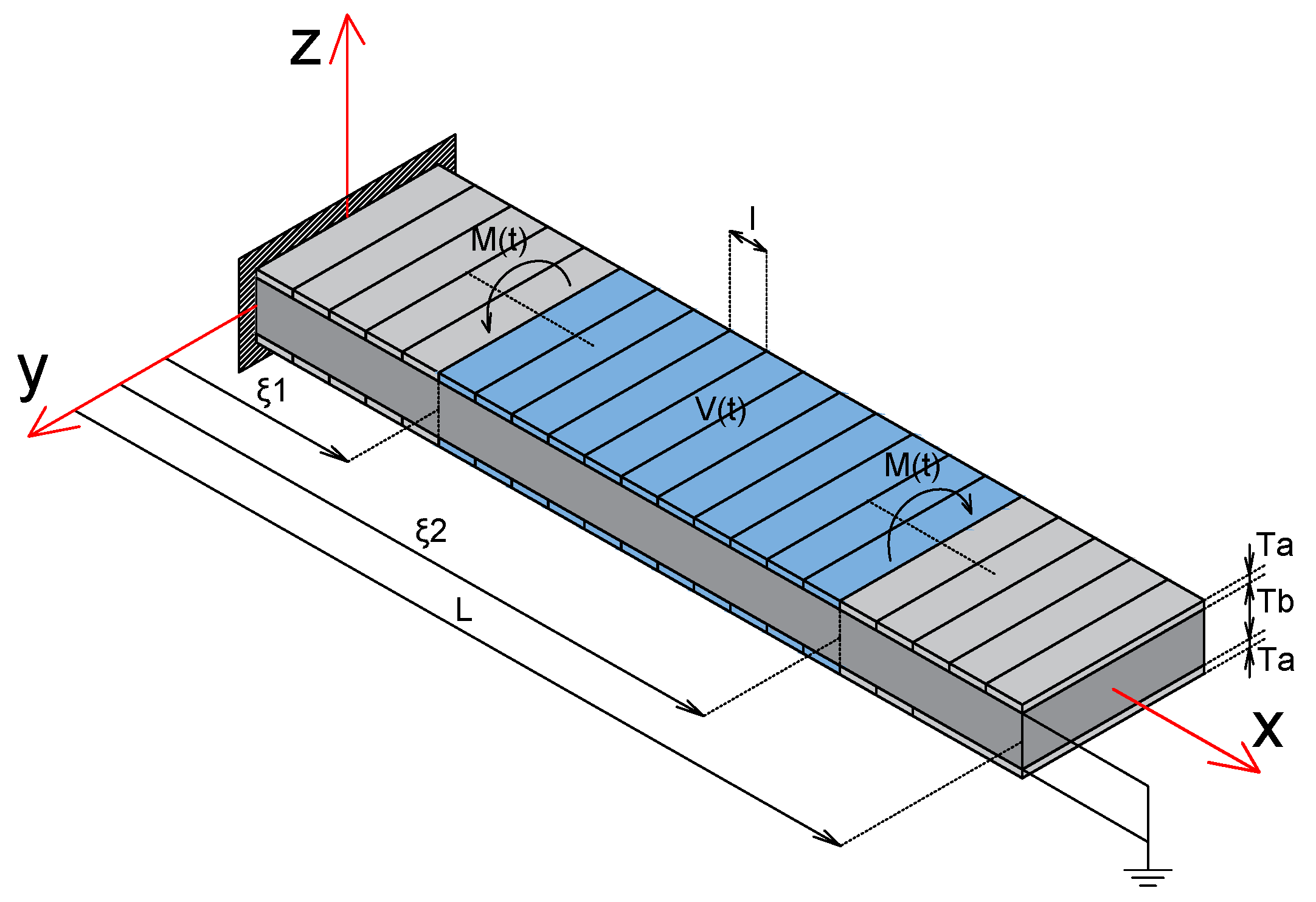
2. Governing Equations for Piezoelectric Coupled Torsional Beam

In Figure 1, a piezoelectric coupled torsional beam is pictured.
The virtual work of the elastic, inertial, applied and piezoelectric forces will be indicated, respectively: δ L e , δ L i n , δ L a , δ L p , so that the principle of the virtual works takes the form:
δ L e = δ L i n + δ L a + δ L p
In [22] the action of the piezoelectric plates has been deeply studied and it can be summarized by two torsional moments concentrated at the end of the plates (Figure 1) with:
M p ( t ) = k V ( t )
V is the electric potential applied to the outer electrodes while the inner ones are grounded.
Indicating with ϕ 0 ( y , z ) the additional warping function and introducing:
Φ 0 = ϕ 0 V
it will be:
k = A Q 55 Φ 0 z y Q 66 Φ 0 y z d A 2 A 1 Q 66 d 36 h L d A
The (2) allows us to write δ L p in a simple form:
δ L p = M p θ ( ξ ¯ 2 ) θ ( ξ ¯ 1 )
where the variables ξ ¯ 1 and ξ ¯ 2 ( ξ ¯ = x L ) can vary within the domain identified by the (6) and depicted in (Figure 2), i.e.,
0 ξ ¯ 1 1 0 ξ ¯ 2 1 0 ξ ¯ 1 ξ ¯ 2
The virtual work of the other forces can be written as:
δ L e = G J 0 L θ x θ x d x
δ L i n = j 0 L 2 θ t 2 θ d x
δ L a = 0 L m θ d x
If the ψ i ( x ) are the torsional modes of the beam, and X i ( t ) their amplitude, θ ( x , t ) can assume the form:
θ ( x , t ) = i = 1 N X i ( t ) ψ i ( x )
being N the number of the modes taken into account.
Using the modal analysis method the (1) assumes the form:
M X . . ( t ) + K X ( t ) = B ( ξ ¯ 1 , ξ ¯ 2 ) V ( t ) + Q ( t )
Having indicated with X = { X 1 ( t ) , X 2 ( t ) , . . X N ( t ) } the modal amplitude vector and with M and K the mass and the stiffness matrices. The vector B ( ξ ¯ 1 , ξ ¯ 2 ) and Q ( t ) are respectively the modal vector control and the applied moment vector with the following expressions:
B ( ξ ¯ 1 , ξ ¯ 2 ) = k ψ 1 ( ξ ¯ 2 ) ψ 1 ( ξ ¯ 1 ) , ψ 2 ( ξ ¯ 2 ) ψ 2 ( ξ ¯ 1 ) , , ψ N ( ξ ¯ 2 ) ψ N ( ξ ¯ 1 ) Q ( t ) = { 0 L m ( x , t ) ψ 1 ( x ) d x , 0 L m ( x , t ) ψ 2 ( x ) d x , , 0 L m ( x , t ) ψ N ( x ) d x }
If the viscous damping is taken into consideration, the equation (11) becomes:
M X . . ( t ) + C X . ( t ) + K X ( t ) = B ( ξ ¯ 1 , ξ ¯ 2 ) V ( t ) + Q ( t )
and for Rayleigh damping the damping matrix C takes the form:
C = α M + β K
Considering the modes ψ i ( x ) as the normal modes ( M = I , K = ω 2 ) and assuming β = 0 the (13) is simplified into:
X . . ( t ) + α X . ( t ) + ω 2 X ( t ) = B ( ξ ¯ 1 , ξ ¯ 2 ) V ( t ) + Q ( t )
In the free end of the beam, the eigenmodes have their maximum amplitude, so that this section is considered as a reference for the vibrations of the whole cantilever beam. Indicating with θ Q ( t ) and θ p ( t ) the rotation of the free end section due to the external applied moment m ( x , t ) and the piezoelectric torsional moment, because of the linearity of the system, it is possible to write the total rotation θ T ( t ) as: θ T ( t ) = θ Q ( t ) + θ p ( t ) . In order to damp the vibrations, the piezoelectric plates must be activated to have θ p ( t ) opposite in phase respect to θ Q ( t ) and in this way, if | θ T | , | θ Q | , | θ p | are the amplitudes of the rotations, it will be:
| θ T | = | θ Q | | θ p |
Considering that the loads that produce the highest vibrations are those with the frequencies equal to the eigenfrequencies of the beam, the focus will be on this type of load. The action of the piezoelectric plates is greater the smaller the amplitude | θ T | is or, in other words (see (16)), as the amplitude | θ p | is increased. In this paper, among all the possible piezoelectric plate distributions, which means among all the possible choices of ( ξ ¯ 1 , ξ ¯ 2 ) , what makes | θ p | maximum will be considered optimal. Considering only loads that excite one or two eigenfrequencies and indicating with i 1 and i 2 the excited modes, the applied moment vector Q will have the following expression:
Q ( t ) = 0 , , Q i 1 ( 1 r ) C o s ( ω i 1 t ) , , Q 2 r C o s ( ω i 2 t ) , , 0
where r is a parameter that distributes the load between the two eigenfrequencies: for r = 0 only the i 1 mode is excited, with r = 1 only the i 2 mode is excited, with 0 < r < 1 the load is distributed between the two eigenfrequencies.
The maximum efficiency of the active control (as mentioned above θ p ( t ) must be opposite in phase to what θ Q ( t ) ) will be when the spectrum of the potential V ( t ) has the same characteristics of the load and is parameterized by the same parameter:
V ( t ) = V ( 1 r ) C o s ( ω i 1 t ) + r C o s ( ω i 2 t )
It has been demonstrated in [4] that in such conditions the X i j ( t ) can be approximated by:
X i j ( t ) B i j V i j Sin ( ω i j t ) α ω i j
Substituting the (19) in (10), the following expression for the amplitude of the rotation of the free end section is obtained:
| θ p ( r , ξ ¯ 1 , ξ ¯ 2 ) | = | B i 1 ( ξ ¯ 1 , ξ ¯ 2 ) V i 1 ψ i 1 ( L ) α ω i 1 | + | B i 2 ( ξ ¯ 1 ξ ¯ 2 ) V i 2 ψ i 2 ( L ) α ω i 2 |
Considering that V i 1 = V ( 1 r ) , V i 2 = V r and introducing the functions (see [4]):
q i 1 ( r , ξ ¯ ) = V k ( 1 r ) α ω i 1 ψ i 1 ( L ) ψ i 1 ( ξ ¯ ) q i 2 ( r , ξ ¯ ) = V k r α ω i 2 ψ i 2 ( L ) ψ i 2 ( ξ ¯ )
the (20) becomes:
| θ p ( r , ξ ¯ 1 , ξ ¯ 2 ) | = | q i 1 ( r , ξ ¯ 2 ) q i 1 ( r , ξ ¯ 1 ) | + | q i 2 ( r , ξ ¯ 2 ) q i 2 ( r , ξ ¯ 1 ) |

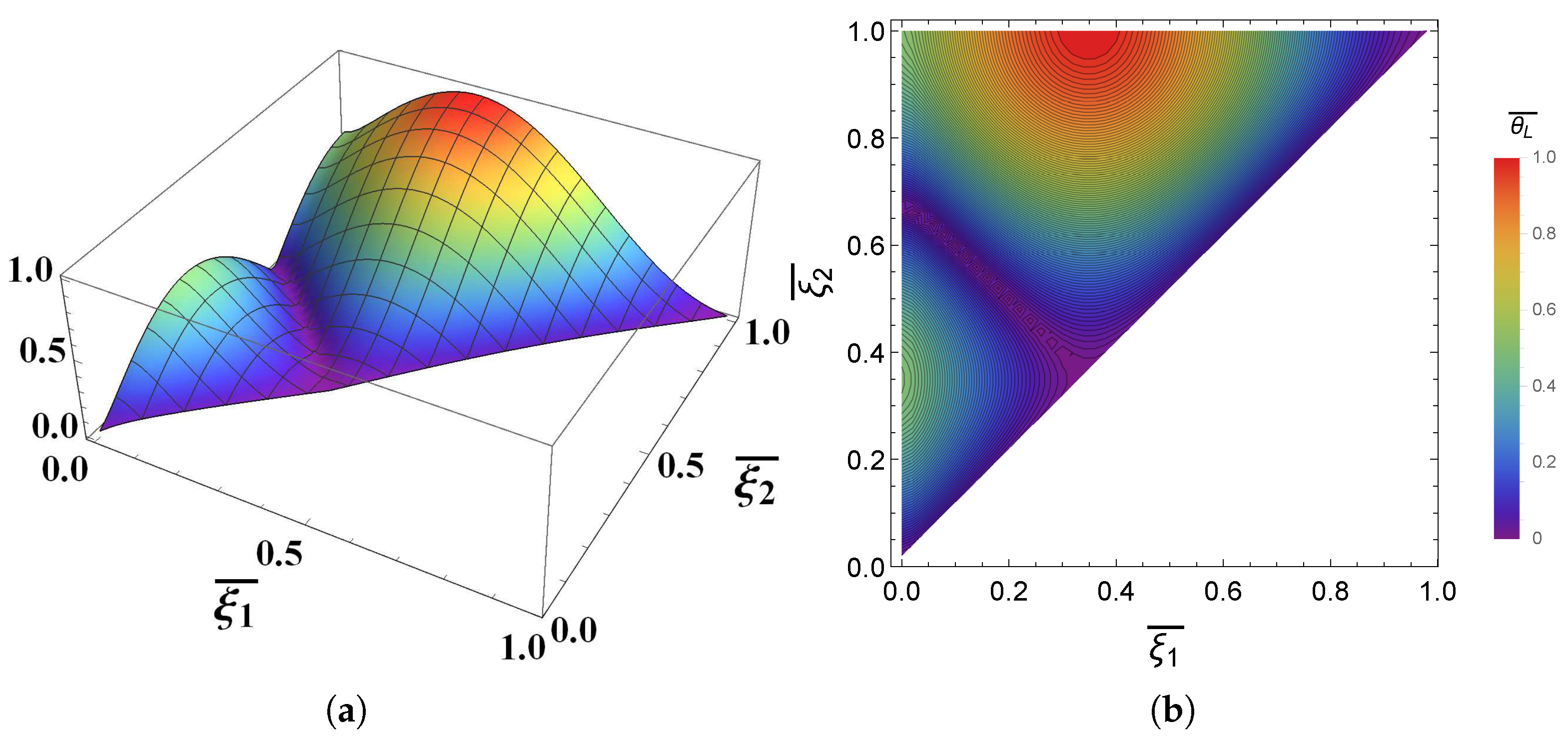
2.1. Damping of One Mode

If the single mode damping is considered, the (22) is reduced to the following form:
| θ p i 1 ( ξ ¯ 1 , ξ ¯ 2 ) | = | q i 1 ( 0 , ξ ¯ 2 ) q i 1 ( 0 , ξ ¯ 1 ) |
Observing that q i 1 ( r , ξ ¯ ) has the same shape of the mode ψ i 1 ( ξ ¯ ) and, in order to maximize | θ p ( r , ξ ¯ 1 , ξ ¯ 2 ) | , analyzing the system (21) it can be noticed that the maximum value is obtained when ξ ¯ 1 and ξ ¯ 2 are the abscissa of a maximum and a minimum, or vice versa, of ψ i 1 ( ξ ¯ ) .

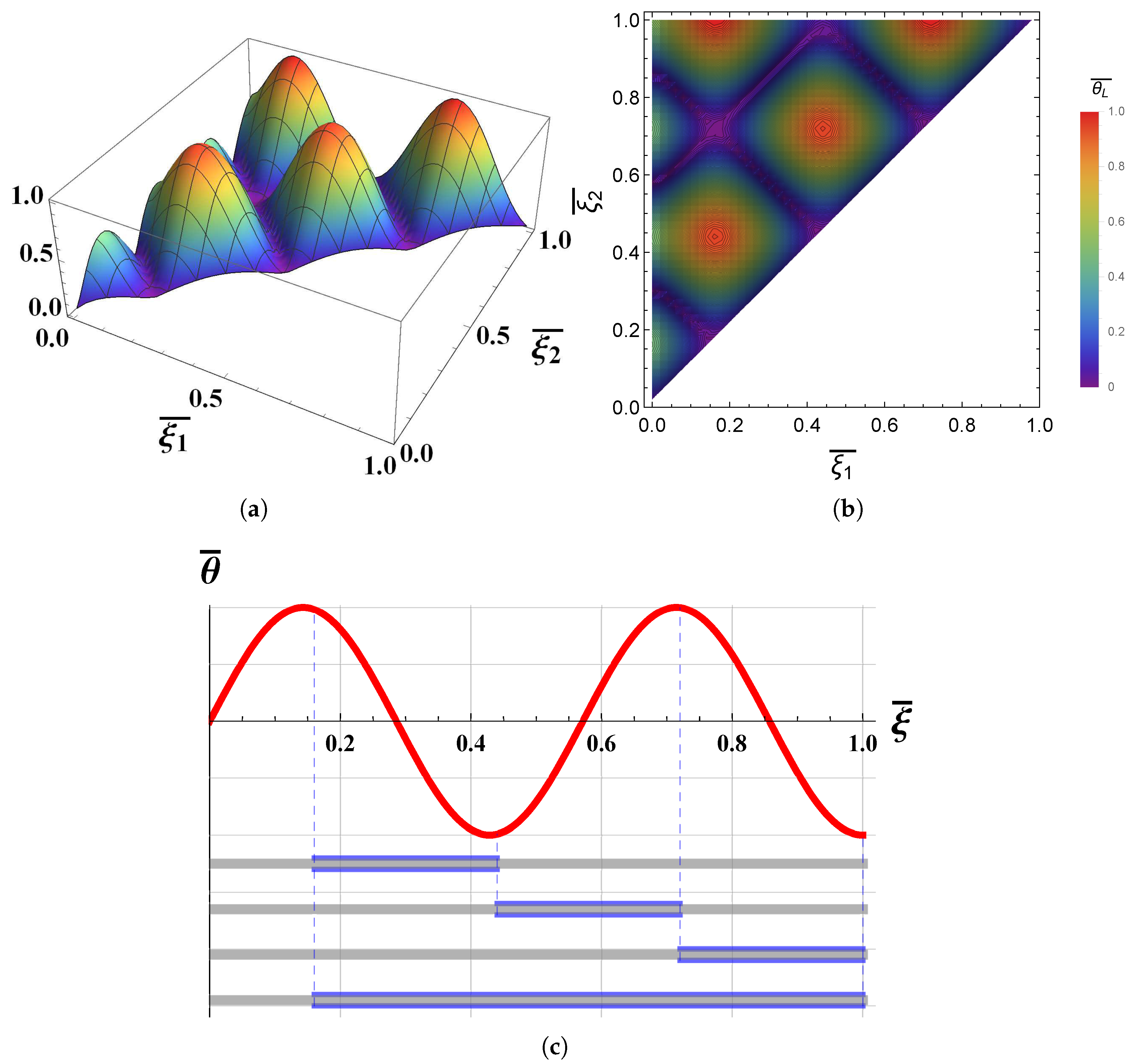
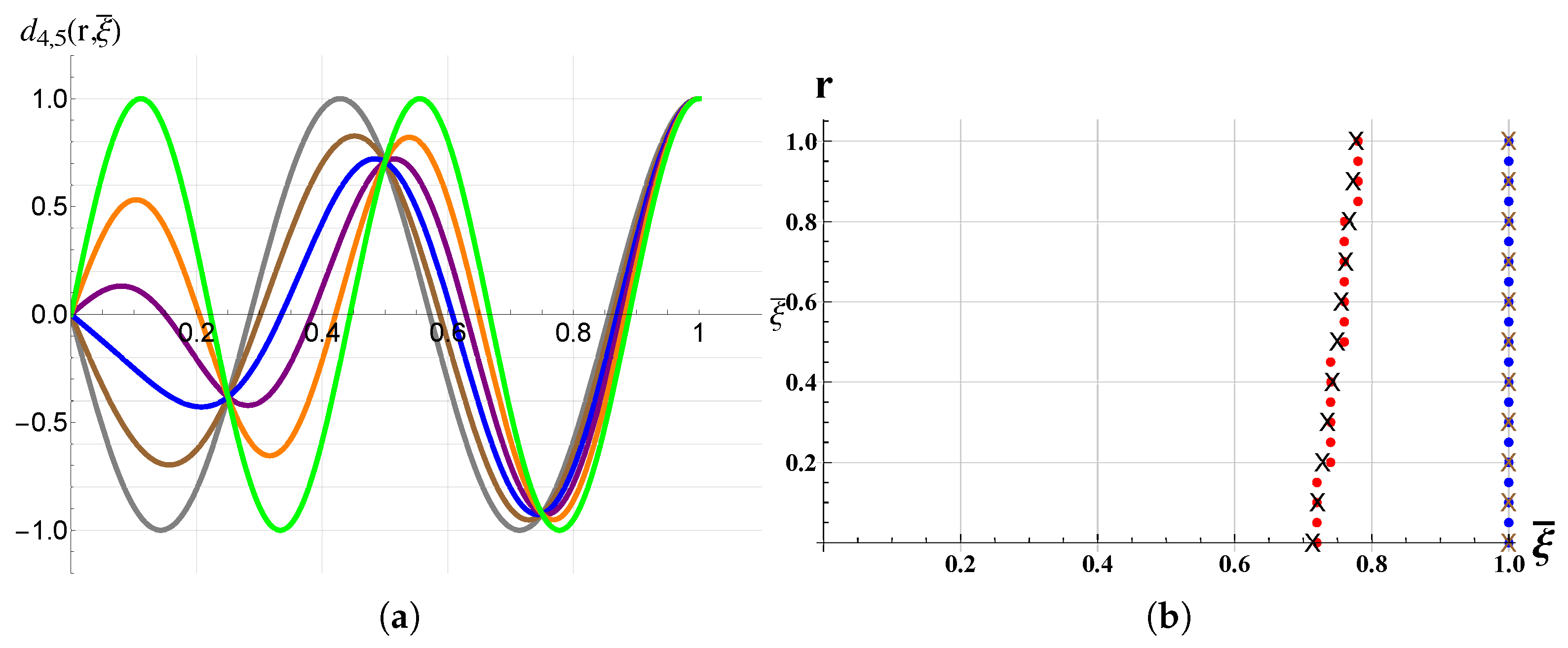
2.2. Damping of Two Combined Modes

Denoting with ( ξ 1 , ξ 2 ) the abscissa and the ordinate of the absolute maximum of | θ p ( r , ξ ¯ 1 , ξ ¯ 2 ) | it will be:
| θ p ( r , ξ ¯ 1 , ξ ¯ 2 ) | m a x = | θ p ( r , ξ 1 , ξ 2 ) | = | q i 1 ( r , ξ 2 ) q i 1 ( r , ξ 1 ) | + | q i 2 ( r , ξ 2 ) q i 2 ( r , ξ 1 ) |
Because of the shape of q j ( r , ξ ¯ ) (see (21)) it is possible to choose ξ 2 = L and considering that:
0 < q j ( r , L ) q j ( r , ξ ¯ ) ξ ¯ [ 0 , 1 ) j N *
Equation (22) becomes:
| θ p ( r , ξ ¯ 1 , ξ ¯ 2 ) | m a x = | θ p ( r , ξ ¯ 1 , L ) | m a x = q i 1 ( r , L ) + q i 2 ( r , L ) d i 1 , i 2 ( r , ξ 1 )
with:
d i 1 , i 2 ( r , ξ ¯ ) = q i 1 ( r , ξ ¯ ) + q i 2 ( r , ξ ¯ ) = V k α [ ( 1 r ) ψ i 1 ( L ) ω i 1 ψ i 1 ( ξ ¯ ) + r ψ i 2 ( L ) ω i 2 ψ i 2 ( ξ ¯ ) ]
From the analysis of the (26), it is deduced that the ordinate ξ 1 of the absolute maximum of | θ p ( r , ξ ¯ 1 , ξ ¯ 2 ) | it is also the abscissa of the absolute minimum of the d i 1 , i 2 ( r , ξ ¯ ) and can be found from the system:
d i 1 , i 2 ( r , ξ ¯ ) ξ ¯ = V k α ( 1 r ) ψ i 1 ( L ) ω i 1 ψ i 1 ( ξ ¯ ) + r ψ i 2 ( L ) ω i 2 ψ i 2 ( ξ ¯ ) = 0 2 d i 1 , i 2 ( r , ξ ¯ ) ξ ¯ 2 = V k α ( 1 r ) ψ i 1 ( L ) ω i 1 ψ i 1 ( ξ ¯ ) + r ψ i 2 ( L ) ω i 2 ψ i 2 ( ξ ¯ ) > 0
The solution of the system provides all the local minima, from these the absolute minimum will be selected.

3. Results and Discussions

In order to validate the model described above, numerical simulations have been done by the frequency response function of a FEM code. The first five eigenmodes, and their pairing, have been taken into account. The optimal placement of the piezoelectric plates is considered to be the one that minimizes the amplitude of θ T or, in other words, the one that maximizes | θ p | (see (16)). The numerical results for the single mode damping are reported in Figure 3, Figure 4, Figure 5, Figure 6 and Figure 7 where in (a) there are the three dimensional plot of the | θ p i ( ξ ¯ 1 , ξ ¯ 2 ) | , in (b) the contour plot of the same function and in (c) the functions ψ i ( ξ ¯ ) and the optimal placement that derives from the numerical simulations. It is possible to observe that the numerical simulations confirm the results predicted by the model; in fact, the ends of the optimal placement coincide always with the positions of a maximum and a minimum (or vice versa) of the considered eigenmode. Obviously when the modal order number increases, the number of optimal positions increases too because the number the extrema of the eigenmode considered increases. The results for coupling between two modes are reported in Figure 8, Figure 9, Figure 10, Figure 11, Figure 12 and Figure 13. In (a) are reported the functions d i 1 , i 2 ( r , ξ ¯ ) for different values of r, in (b) the comparison between numerical and model results. By the FEM simulations, the optimal positions for different combination of modes, of the left ends (red points) and the right ends (blue points) of the piezoelectric plates have been reported. The × represent the analogous results for the analytical model; it is possible to observe that they are in very good agreement with the numerical simulations. It is possible to notice that, when r increases, while the right end remains fixed at the free end there is a shift of the left end towards the free end. This different behavior can be explained by observing the shape of d i 1 , i 2 ( r , ξ ¯ ) and how it changes with r. In fact it is noted that while the position of the absolute maximum in ξ 2 = L (that coincides with the position of the right ends of the piezoelectric plates in their optimal position) never change and remains fixed at the free end, this is not so for the absolute minimum close to it. Indeed, the increment of r induces a transition to a higher vibrational mode ( i 2 > i 1 ) and a consequent movement of this absolute minimum of d i 1 , i 2 ( r , ξ ¯ ) toward the right. For example, observing d 2 , 3 ( r , ξ ¯ ) (but it is the same for all functions) for r = 0 the shape of d 2 , 3 ( 0 , ξ ¯ ) is that of the second torsional mode with an absolute minimum in ξ ¯ 0 . 33 while for r = 1 it has the shape of the third torsional mode with an absolute minimum in ξ ¯ 0.6 . For values of r between 0 and 1, this absolute minimum is located between these two values. Thus, the sharp transition of the left end near r = 1 for coupling between first and third mode and between second and fifth mode is explained. Focusing on d 1 , 3 ( r , ξ ¯ ) , for example, it is noted that for r = 0 this absolute minimum is in ξ ¯ = 0 , as r grows a relative minimum appears ( r = 0.6 , r = 0.8 ) but this becomes an absolute minima only when r > 0.9 .

4. Conclusions

In this paper, a new model for the optimal placement of the piezoelectric plates to damp a single mode or multimodes torsional vibrations has been proposed. The model outcomes are compared with the results of numerical simulations and a good agreement among them has been found. Future works will focus on the implementation of the model in the case of rotating cantilever beams. The interest of these studies could be, e.g., the damping of the blade vibrations in turbomachinery.

Author Contributions

F.B. designed and developed the model and wrote the paper. F.T. carried out the numerical simulations.

Conflicts of Interest

The authors declare no conflict of interest.

Nomenclature

Bcontrol vector
C damping matrices
d 36 piezoelectric coefficient
jpolar moment of inertia per unit length
JSt Venant torsion constant
K stiffness matrices
Gshear modulus
Lbeam length
mapplied moment per unit length
M p piezoelectric torsional moment
M mass matrices
Q applied moment vector
rratio of the j-th component of the tension
Vvoltage applied to the piezoelectric plates
α damping coefficient
β damping coefficient
θ angle of twist
θ virtual angle of twist
ξ non dimensional length
ϕ 0 warping function
x ¯ adimensional length of the beam: x L b
X i modal amplitude
ψ i torsional modes
ω i natural frequency
Superscripts
virtual quantity
non dimensional length

References

  1. Alkhatib, R.; Golnaraghi, M.F. Active structural vibration control: A review. Shock Vib. Dig. 2003, 35, 367–383. [Google Scholar] [CrossRef]
  2. Weber, F.; Distl, H.; Fischer, S.; Braun, C. MR damper controlled vibration absorber for enhanced mitigation of harmonic vibrations. Actuators 2016, 54, 27. [Google Scholar] [CrossRef]
  3. Yang, S.-Y.; Han, C.; Shin, S.-U.; Choi, S.-B. Design and Evaluation of a Semi-Active Magneto-Rheological Mount for a Wheel Loader Cabin. Actuators 2017, 62, 16. [Google Scholar]
  4. Botta, F.; Dini, D.; Schwingshackl, C.; di Mare, L.; Cerri, G. Optimal placement of piezoelectric plates to control multimodal vibrations of a beam. Adv. Acoust. Vib. 2013, 2013, 10:1–10:8. [Google Scholar]
  5. Baz, A.; Poh, S. Performance of an active control system with piezoelectric actuators. J. Sound Vib. 1988, 126, 327–343. [Google Scholar] [CrossRef]
  6. Chopra, I. Review of state of art of smart structures and integrated system. AIAA J. 2002, 40, 2145–2187. [Google Scholar] [CrossRef]
  7. Yan, B.; Wang, K.; Hu, Z.; Wu, C.; Zhang, X. Shunt Damping Vibration Control Technology: A Review. Appl. Sci. 2017, 7, 494. [Google Scholar] [CrossRef]
  8. Herold, S.; Mayer, D. Adaptive Piezoelectric Absorber for Active Vibration Control. Actuators 2016, 5, 7. [Google Scholar] [CrossRef]
  9. Al Hamidi, Y.; Rakotondrabe, M. Multi-Mode Vibration Suppression in MIMO Systems by Extending the Zero Placement Input Shaping Technique: Applications to a 3-DOF Piezoelectric Tube Actuatorl. Actuators 2016, 5, 13. [Google Scholar] [CrossRef]
  10. Alvarez, N.; Cardoni, A.; Cerisola, N.; Riera, E.; Andrade, M.A.B.; Adamowski, J.C. Nonlinear Dynamic Modeling of Langevin-Type Piezoelectric Transducers. Actuators 2015, 4, 255–266. [Google Scholar] [CrossRef]
  11. Guo, K.; Xu, Y. Random Vibration Suppression of a Truss Core Sandwich Panel Using Independent Modal Resonant Shunt and Modal Criterion. Appl. Sci. 2017, 7, 496. [Google Scholar] [CrossRef]
  12. Botta, F.; Cerri, G. Wave propagation in Reissner-Mindlin piezoelectric coupled cylinder with non-constant electric field through the thickness. Int. J. Solids Struct. 2007, 44, 6201–6219. [Google Scholar] [CrossRef]
  13. Wang, S.Y.; Tai, K.; Quek, S.T. Topology optimization of piezoelectric sensor/actuators for torsional vibration control of composite plates. Smart Mater. Struct. 2006, 15, 253–269. [Google Scholar] [CrossRef]
  14. Crawley, E.F.; de Luis, J. Use of piezoelectric actuators as elements of intelligent structures. AIAA J. 1987, 25, 1373–1385. [Google Scholar] [CrossRef]
  15. Botta, F.; Scorza, A.; Rossi, A. Optimal Piezoelectric Potential Distribution for Controlling Multimode Vibrations. Appl. Sci. 2018, 8, 551. [Google Scholar] [CrossRef]
  16. Botta, F.; Marx, N.; Schwingshackl, C.W.; Cerri, G.; Dini, D. A wireless vibration control technique for gas turbine blades using piezoelectric plates and contactless energy transfer. In Proceedings of the ASME Turbo Expo 2013: Turbine Technical Conference and Exposition, San Antonio, TX, USA, 3–7 June 2013; GT2013-95666. p. V07AT32A006. [Google Scholar]
  17. Botta, F.; Marx, N.; Gentili, S.; Schwingshackl, C.W.; Di Mare, L.; Cerri, G.; Dini, D. Optimal placement of piezoelectric plates for active vibration control of gas turbine blades: Experimental results. Proc. SPIE Int. Soc. Opt. Eng. 2012, 8345, 83452H. [Google Scholar]
  18. Park, C.; Walz, C.; Chopra, I. Bending and torsion models of beams with induced-strain actuators. Smart Mater. Struct. 1996, 5, 98–113. [Google Scholar]
  19. Park, C.; Chopra, I. Modeling piezoceramic actuation of beams in torsion. AIAA J. 1996, 34, 2582–2589. [Google Scholar] [CrossRef]
  20. Aldraihem, O.J.; Wetherhold, R.C. Mechanics and control of coupled bending and twisting vibration of laminated beams. Smart Mater. Struct. 1997, 6, 123. [Google Scholar] [CrossRef]
  21. Spearritt, D.J.; Asokanthan, S.F. Torsional vibration control of a flexible beam using laminated PVDF actuators. J. Sound Vib. 1996, 193, 941–956. [Google Scholar] [CrossRef]
  22. Zehetner, C. Compensation of torsion in rods by piezoelectric actuation. Arch. Appl. Mech. 2008, 78, 921–933. [Google Scholar] [CrossRef]
  23. Zehetner, C. Compensation of torsional vibrations in rods by piezoelectric shear actuators. Acta Mech. 2009, 207, 121–133. [Google Scholar] [CrossRef]
  24. Sunar, M.; Rao, S.S. Distribuited Modeling and Actuator Location for Piezoelectric Control System. AIAA J. 1996, 34, 2209–2221. [Google Scholar] [CrossRef]
  25. Demetriou, M.A. A Numerical Algorithm for the Optimal Placement of Actuators and Sensors for Flexible Structures. In Proceedings of the American Control Conference, Chicago, IL, USA, 28–30 June 2000; pp. 2290–2294. [Google Scholar]
  26. Barboni, R.; Mannini, A.; Fantini, E.; Gaudenzi, P. Optimal placement of PZT actuators for the control of beam dynamics. Smart Mater. Struct. 2000, 9, 110–120. [Google Scholar] [CrossRef]
  27. Aldraihem, O.J.; Singh, T.; Wetherhold, R.C. Optimal Size and Location of Piezoelectric Actuator/Sensors: Practical Considerations. J. Guid. Control Dyn. 2000, 23, 509–515. [Google Scholar] [CrossRef]
  28. Wang, Q.; Wang, C.M. Optimal placement and size of piezoelectric patches on beams from the controllability perspective. Smart Mater. Struct. 2000, 9, 558–567. [Google Scholar] [CrossRef]
  29. Bruant, I.; Coffignal, G.; Lene, F.; Verge, M. A methodology for determination of piezoelectric actuator and sensor location on beam structures. J. Sound Vib. 2001, 245, 861–882. [Google Scholar] [CrossRef]
  30. Frecker, M.I. Recent Advances in Optimization of Smart Structures and Actuators. J. Intell. Mater. Syst. Sruct. 2003, 14, 207–216. [Google Scholar] [CrossRef]
  31. Yang, Y.; Jin, Z.; Soh, C.K. Integrated optimal design of vibration control system for smart beams using genetic algorithms. J. Sound Vib. 2005, 119, 487–508. [Google Scholar] [CrossRef]
  32. Dhuri, K.D.; Seshu, P. Piezo actuator placement and sizing for good control effectiveness and minimal change in original system dynamics. Smart Mater. Struct. 2006, 15, 1661–1672. [Google Scholar] [CrossRef]
  33. Kumar, K.R.; Narayanan, S. Active vibration control of beams with optimal placement of piezoelectric sensor/actuator pairs. Smart Mater. Struct. 2008, 17, 1–15. [Google Scholar]
  34. Gupta, V.; Sharma, M.; Nagesh, T. Optimization Criteria for Optimal Placement of Piezoelectric Sensors and Actuators on a Smart Structure: A Technical Review. J. Intell. Mater. Syst. Struct. 2010, 21, 1227–1243. [Google Scholar] [CrossRef]
Figure 1. Beam with piezoelectric torsional actuator.
Actuators 07 00023 g001
Figure 2. { ξ ¯ 1 , ξ ¯ 2 } domain.
Actuators 07 00023 g002
Figure 3. Optimal placement for the damping of the first torsional mode. (a) Three dimensional plot of the | θ p 1 ( ξ ¯ 1 , ξ ¯ 2 ) | ; (b) Contour plot of the | θ p 1 ( ξ ¯ 1 , ξ ¯ 2 ) | ; (c) The function ψ 1 ( ξ ¯ ) and the optimal placement from the numerical simulations.
Actuators 07 00023 g003
Figure 4. Optimal placement for the damping of the second torsional mode. (a) Three dimensional plot of the | θ p 2 ( ξ ¯ 1 , ξ ¯ 2 ) | ; (b) Contour plot of the | θ p 2 ( ξ ¯ 1 , ξ ¯ 2 ) | ; (c) The function ψ 2 ( ξ ¯ ) and the optimal placement from the numerical simulations.
Actuators 07 00023 g004aActuators 07 00023 g004b
Figure 5. Optimal placement for the damping of the third torsional mode. (a) Three dimensional plot of the | θ p 3 ( ξ ¯ 1 , ξ ¯ 2 ) | ; (b) Contour plot of the | θ p 3 ( ξ ¯ 1 , ξ ¯ 2 ) | ; (c) The function ψ 3 ( ξ ¯ ) and the optimal placement from the numerical simulations.
Actuators 07 00023 g005
Figure 6. Optimal placement for the damping of the fourth torsional mode. (a) Three dimensional plot of the | θ p 4 ( ξ ¯ 1 , ξ ¯ 2 ) | ; (b) Contour plot of the | θ p 4 ( ξ ¯ 1 , ξ ¯ 2 ) | ; (c) The function ψ 4 ( ξ ¯ ) and the optimal placement from the numerical simulations.
Actuators 07 00023 g006
Figure 7. Optimal placement for the damping of the fifth torsional mode. (a) Three dimensional plot of the | θ p 5 ( ξ ¯ 1 , ξ ¯ 2 ) | ; (b) Contour plot of the | θ p 5 ( ξ ¯ 1 , ξ ¯ 2 ) | ; (c) The function ψ 5 ( ξ ¯ ) and the optimal placement from the numerical simulations.
Actuators 07 00023 g007aActuators 07 00023 g007b
Figure 8. Optimal placement for coupling between first and second mode. (a) _: r = 0.0; _: r = 0.2; _: r = 0.4; _: r = 0.6; _: r = 0.8; _: r = 1.0; (b) Comparison between numerical and model results. : FEM simulations; ×: model results.
Actuators 07 00023 g008
Figure 9. Optimal placement for coupling between second and third mode. (a) _: r = 0.0; _: r = 0.2; _: r = 0.4; _: r = 0.6; _: r = 0.8; _: r = 1.0; (b) Comparison between numerical and model results. : FEM simulations; ×: model results.
Actuators 07 00023 g009
Figure 10. Optimal placement for coupling between third and fourth mode. (a) _: r = 0.0; _: r = 0.2; _: r = 0.4; _: r = 0.6; _: r = 0.8; _: r = 1.0; (b) Comparison between numerical and model results. : FEM simulations; ×: model results.
Actuators 07 00023 g010
Figure 11. Optimal placement for coupling between fourth and fifth mode. (a) _: r = 0.0; _: r = 0.2; _: r = 0.4; _: r = 0.6; _: r = 0.8; _: r = 1.0; (b) Comparison between numerical and model results. : FEM simulations; ×: model results.
Actuators 07 00023 g011
Figure 12. Optimal placement for coupling between first and third mode. (a) _: r = 0.0; _: r = 0.2; _: r = 0.4; _: r = 0.6; _: r = 0.8; _: r = 1.0; (b) Comparison between numerical and model results. : FEM simulations; ×: model results.
Actuators 07 00023 g012
Figure 13. Optimal placement for coupling between second and fifth mode. (a) _: r = 0.0; _: r = 0.2; _: r = 0.4; _: r = 0.6; _: r = 0.8; _: r = 1.0; (b) Comparison between numerical and model results. : FEM simulations; ×: model results.
Actuators 07 00023 g013

