Abstract
This paper proposes an enhancement of the Bouc–Wen hysteresis model to capture the frequency-dependent hysteretic behavior of a thin bimorph-type piezoelectric actuator which also exhibits odd harmonic oscillation (OHO) at specific input frequencies. The odd harmonic repetitive controller has recently been proposed to compensate for the hysteresis, and attenuates the OHO of the piezoelectric actuator for which the hysteresis nonlinearity is regarded as a disturbance. This paper proposes an alternate treatment of the hysteresis compensation with the attenuation of the OHO observed at some input frequencies. It will be shown that the proposed compensator fully utilizes the mathematical structure of the enhanced Bouc–Wen model proposed in this paper to compensate the hysteresis and to attenuate the OHO. The results of the hysteresis compensation experiment illustrate the excellent performance of the proposed control system, especially at the frequencies where OHO is conspicuous.
1. Introduction
Piezoelectric actuators are widely used both in industries and in consumer appliances because of their advantages in size, fine positioning capability, and quick response characteristics. Examples of their application include the nanopositioning stage of the atomic force microscope (AFM) [], HDD head positioning [], and the actuation of a micro-robot []. However, it is well-known to the researchers and practitioners in the field that hysteresis is observed in the response of the piezoelectric actuator to its inputs, and the positioning accuracy is severely deteriorated if no appropriate compensation is given. Great efforts have hence been devoted to the modeling and compensation of hysteresis.
Many mathematical models have been developed to capture the behavior of the hysteresis nonlinearity. Most of the models are phenomenological in the sense that the structure of the models are not necessarily physically motivated, but determined to numerically represent the behavior as precisely as possible. The phenomenological hysteresis models proposed to-date include the Preisach model and its extensions [,], the Prandtl–Ishlinskii model [], and the Bouc–Wen model [].
Among the models stated in the previous paragraph, the Bouc–Wen model has attracted great attention from researchers because of its mathematical simplicity, and the model has been used extensively in both the modeling and compensation of various hysteresis-related phenomena. Rakotondrabe [] proposed a control system to compensate hysteresis nonlinearity using the Bouc–Wen model. His work can be classified as feedforward control in the control engineering context. His excellent contribution owes its theoretical basis to the structure of the Bouc–Wen model, and there is no need to synthesize the inverse hysteresis model to cancel the hysteresis. The authors of the current paper recently proposed an extension of the Bouc–Wen model [] to capture the behavior of a thin bimorph-type piezoelectric actuator which exhibits frequency-dependent hysteresis, and synthesized a compensator based on the idea proposed by Rakotondrabe. Hadineza et al. [] formulated the multi-variable generalized Bouc–Wen model and used it in the control of their experimental plant, in which multiple piezoelectric actuators are installed.
Recently, Li et al. [] reported the existence of a special form of frequency-dependent hysteresis nonlinearity in their piezo-driven nanopositioning stage which is referred to as the odd harmonic oscillation (OHO). We have also observed the odd harmonic oscillation with our bimorph piezoelectric actuator (e.g., the response to a 23 Hz pure sinusoidal input shown in Figure 18 []). Li clearly stated that the odd harmonic oscillation is caused by the hysteresis nonlinearity of the piezoelectric actuator, but they treated it as a disturbance and synthesized an odd harmonic repetitive controller to attenuate the odd harmonic oscillation. We are highly motivated by the work of Li et al., as we believe that attenuation of the odd harmonic oscillation can be treated in the course of model-based hysteresis compensation. The present paper accordingly addresses the results of our effort on modeling the frequency-dependent hysteresis of a thin bimorph piezoelectric actuator which also exhibits OHO. We will hereafter refer to the model proposed in this paper as the enhanced Bouc–Wen model.
We will also propose a controller design based on the enhanced Bouc–Wen model which compensates the hysteresis nonlinearity and attenuates the adherent OHO. The proposed controller has a combined feedforward (FF) and feedback (FB) architecture. Many foregoing works can be found in the literature which employ the FF + FB architecture to control the piezoelectric actuator. This architecture is classified as a two degrees of freedom (2 d.o.f.) control system in the control engineering context. Many preceding works which use the 2 d.o.f. controller assign the role of hysteresis compensation to the feedforward controller and the accompanied feedback controller is synthesized to compensate the inaccuracy, uncertainties, or to provide performance enhancement []. Examples of this type include the works by Xu and Li [] and Li et al. [].
There are also works which utilize the feedforward controller for an objective other than hysteresis compensation. A prime example can be found in the works by Rakotondrabe et al. [,], in which ZV input shaping [] is adopted to synthesize feedforward control input for vibration suppression of their 2-d.o.f. piezocantilever. The ZV input shaping technique generates a command signal sequence which includes several impulse inputs. However, as it is a feedforward control method, it requires parameter identification prior to the command signal calculation, and the control performance will be deteriorated when only inaccurate system parameters are available. This paper proposes a controller to attenuate the unwanted odd harmonic oscillation. It can be said that the proposed control method for the attenuation of odd harmonic oscillation is an enhancement of ZV input shaping using feedback.
This paper is organized as follows. Section 2 states the derivation of the enhanced Bouc–Wen model and details the development to introduce the inherent odd harmonic oscillation of a piezoelectric actuator into the model. The procedure for the identification of the proposed enhanced Bouc–Wen model is also addressed in the section. Section 3 dictates the identification experiment and its results. Section 4 describes the details of the hysteresis compensator design which simultaneously attenuates the odd harmonic oscillation. Section 5 illustrates the results of the hysteresis compensation experiment, and conclusions are drawn in Section 6.
2. Modeling the Behavior of Piezoelectric Actuator with the Bouc–Wen model
2.1. Extended Bouc–Wen Model for Bimorph Piezoelectric Actuator Showing Asymmetric Hysteresis Loop
The Bouc–Wen model is one form of phenomenological hysteresis model which was originally proposed by Bouc and later generalized by Wen []. The Bouc–Wen model can be applied to many mechanical systems. The original Bouc–Wen model employs a mechanical excitation as its input. A Bouc–Wen model for a cantilevered piezoelectric actuator has been proposed in the literature [] which is described by a set of equations:
where u denotes the input driving voltage applied to the actuator, h represents the state of the model, and y amounts to the output displacement of the actuator [,]. The parameters , and determine the geometric properties of the hysteresis loop obtained with the model (1): A governs the amplitude, and define the shape, and is a gain constant between the input and the output. We will elaborate on the extension of this model in the discrete time domain in this article. The discrete version of (1) is given by
We applied the forward difference calculation to the time derivative terms for the discretization of Equation (1). This would yield the appearance of the term in the right hand side of the first equation, which prevents its online calculation. We accordingly replace the discrete time step symbol k with to have the expression shown in the first equation of (2).
However, it is known that real-world piezoelectric actuators sometimes exhibit asymmetric hysteresis loops whose centers are off the origin of the input/output plane. Figure 1 shows a photo of the bimorph piezoelectric actuator (PZBA-00030, FDK, Tokyo, Japan) used in this study. This actuator exhibits large bending displacement with a low-voltage driving signal. It has a low mechanical resonance frequency, as shown in Table 1, which summarizes the physical specifications of the actuator. We have been working on the controller design of this thin bimorph actuator because this actuator shows rate-dependent hysteresis, phase lag to high-frequency inputs, and some other interesting properties as a target of academic research. Figure 2 shows an example of the response of this piezoelectric actuator. We can observe an asymmetric hysteresis loop whose center is off the origin of the input/output plane.
Figure 1.
The bimorph type piezoelectric actuator PZBA-00030 by FDK used in this study.
Table 1.
Specification of FDK PZBA-00030.
Figure 2.
An example of the off-center asymmetric hysteresis loop of the piezoelectric actuator used in this study.
Additional difficulty arises in the modeling of the bimorph piezoelectric actuator as the frequency of the driving input signal increases. This difficulty is the phase lag between the input and the output. It will appear simultaneously with the hysteresis of the actuator. Figure 3 shows the input/output plane trajectory of the actuator response to a 35 Hz pure sinusoidal input. This is a hysteresis loop of the actuator. However, the zoomed part of the figure clearly shows that the output response of the actuator exhibits phase lag to the driving input signal. This behavior cannot be seen in Figure 2. The source of actuator displacement is physically an inverse piezoelectric effect which exhibits hysteresis. It is natural to infer that the model we develop should have mathematical structures to account for both the hysteresis and the phase lag originating from the cantilever structure of the actuator. We have accordingly proposed the extended Bouc–Wen model to capture this behavior []. The extended Bouc–Wen model is formulated by
where is the model output, is the input, and represents the hysteresis component, all at time sample k. This model can be obtained by replacing the symbol A in (2) with the expression , intending to introduce the velocity sign sensitivity to the behavior of the model which would lead to the asymmetric off-center hysteresis loop formation. It is fair to say that this idea is a simplified version of the generalized Bouc-Wen model proposed in []. The IIR filter structure that can be found in the second equation is a mathematical representation of the structural dynamics of the thin bimorph actuator. The symbols , and form the set of parameters of the extended Bouc–Wen model. Figure 4 illustrates the capability of the extended Bouc–Wen model (3). This response was calculated using the model (3) with fictitious parameter values. Phase lag can be observed clearly in Figure 4.
Figure 3.
Input/output map of the response of the actuator to 35 Hz pure sinusoidal input. The zoomed part of the figure clearly shows that the output displacement takes its maximum value when the input already starts decreasing.
Figure 4.
An example of the response of the extended Bouc–Wen model (3) with fictitious parameter values. (a) Input/output plane; (b) Time domain.
2.2. Proposed Enhancement of the Bouc–Wen Model for Frequency-Dependent Hysteresis with Odd Harmonic Oscillation
There is one more peculiarity observed in the behavior of the bimorph piezoelectric actuator. Figure 5 shows the responses of our piezoelectric actuator to sinusoidal inputs whose frequencies are (a) 14 Hz and (b) 23 Hz, respectively. Figure 2 and Figure 5a,b clearly show that the shape of the hysteresis loops may differ greatly as the frequency of the sinusoidal input signal varies. We performed a fast Fourier transform (FFT) analysis on the responses of the piezoelectric actuator to 1, 14, 15, and 23 Hz sinusoidal inputs. The results are summarized in Figure 6. It is clear that the response to the 14 Hz input contains a 70 Hz element and the response to the 23 Hz input includes a 69 Hz component. These two are the prime examples showing that the piezoelectric actuator occasionally exhibits odd harmonic oscillation.
Figure 5.
Actuator responses to (a) 14 Hz and (b) 23 Hz sinusoidal inputs plotted in the input/output plane.
Figure 6.
The results of the fast Fourier transform (FFT) analysis of the responses of our piezoelectric actuator to (a) 1, (b) 14, (c) 15, and (d) 23 Hz sinusoidal inputs.
The bandwidth of the bimorph piezoelectric actuator we use in this study is comparably lower than other piezoelectric actuators. Figure 7 shows the frequency characteristics of the output displacement of this piezoelectric actuator. The actuator seems to have a mechanical resonance around 70 Hz, and external excitation higher than 80 Hz will be rolled off. Although we measured the displacement of the actuator at a 1 kHz sampling rate and performed the frequency analysis, we could not find spectrum corresponding to higher (more than fifth or seventh) odd harmonics. Because we intend to synthesize a controller for pure sinusoidal reference whose frequency is up to 50 Hz in this study, and we can only observe the third or fifth harmonic in this input range, we will concentrate on modeling the third and fifth harmonic components of the odd harmonics in the rest of the development.
Figure 7.
Frequency response characteristics of the bimorph piezoelectric actuator used in this study. It was measured experimentally using a pure sinusoidal input whose frequency was altered from 1 Hz to 100 Hz. It can be seen that this actuator has mechanical resonance at approximately 70 Hz.
In order to incorporate the third or the fifth harmonic response into the Bouc–Wen model, it is necessary to augment the structure of the extended Bouc–Wen model to include the odd harmonic oscillation. One elementary attempt is to use the exogenous input
to excite the third-order harmonic, and use when necessary
to excite the fifth-order harmonic, where f is the base frequency of excitation and represents the sampling interval. Li et al. [] stated that the odd harmonic oscillation is caused by the hysteresis nonlinearity. It is a natural consequence to infer that the structural dynamics will affect the odd harmonic oscillation of the actuator used in this study. We thus propose the sets of equations
to capture the frequency-dependent hysteresis of the thin bimorph piezoelectric actuators exhibiting the third-order harmonic, and
for frequency-dependent hysteresis with the fifth-order harmonic, where represents the response to the input of fundamental excitation frequency and () represents the third (fifth) harmonic response. The term in (6) or in (7) should be regarded as the model of the hysteresis nonlinearity which causes the odd harmonic response. We still use the IIR structure in the third equation of (6) and (7), as the output displacement of the actuator can only be observed through the structural oscillation of the actuator. Figure 8 shows an example of the response of the frequency-dependent hysteresis model (6) with the third-order harmonic oscillation to 23 Hz sinusoidal input. The twisted shape of the hysteresis loop as observed in Figure 8a is caused by the 69 Hz component of the response which is included in the model (6).
Figure 8.
An example of the numerical response of the third-order harmonic hysteresis model (6) to 23 Hz sinusoidal input. (a) Hysteresis loop in the input/output plane; (b) Its time domain representation.
2.3. Preparation for the Parameter Identification
We used the recursive least square (RLS) algorithm to identify the model parameters included in (6) or (7). Both of these equations can be written in the form
with the appropriate choices of the parameter vector and the regressor . For the proposed enhanced Bouc–Wen model (6) which captures the third-order harmonic oscillation, we have
and similarly
for the fifth-order harmonic model (7). In the experimental verification disclosed in Section 5 , we will use our extended Bouc–Wen model in [] for comparison. It is easy to see that the extended Bouc–Wen model can also be written in the linear regression form (8) and the algebraic descriptions of and for the extended Bouc–Wen model are omitted accordingly.
3. Identification Experiment
A parameter identification experiment and a numerical validation of the identified model were conducted to claim the high modeling accuracy of the proposed enhanced Bouc–Wen model (6) and (7). 
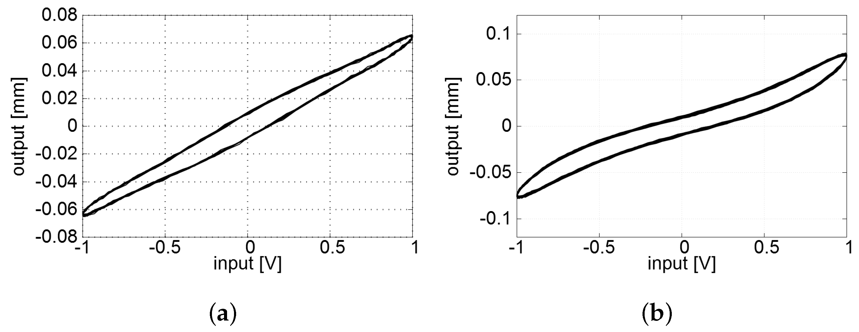
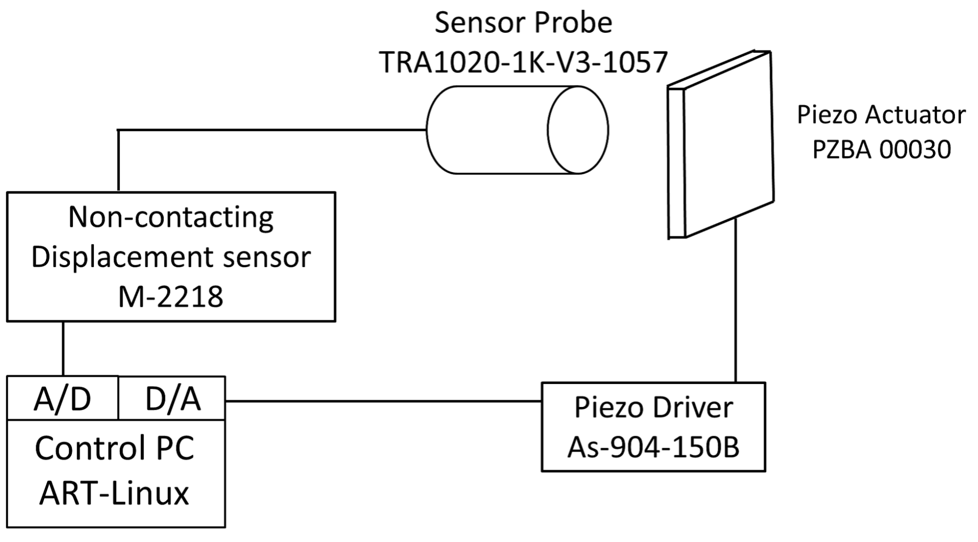
Figure 9 shows the measurement setup. A pure sinusoidal input
was calculated by the PC driven by the 3.2 GHz CPU (AMD, phenomX4 955, Santa Clara, CA, USA) and fed to the piezoelectric actuator via D/A converter (Interface, LPC-361116, Hiroshima, Japan) and a bipolar piezo driver (NF, As-904-150B, Yokohama, Japan) in 
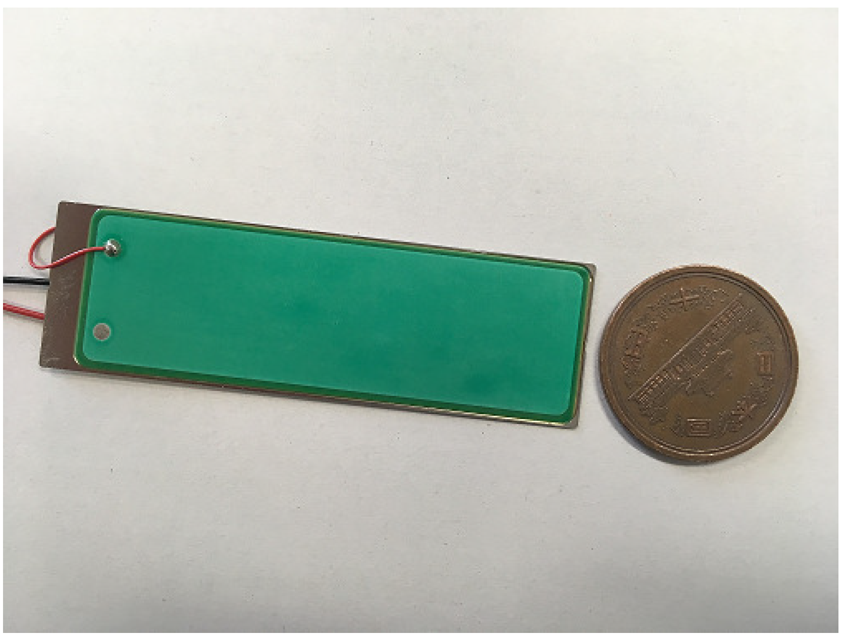
Figure 9. The PC worked with the realtime operating system ART-Linux with a sampling interval of 1 ms. A capacitance-type displacement sensor (MESS-TEK, M-2218, Wako, Japan) together with a probe (MESS-TEK, TRA10251K-V3) were used to measure the displacement of the actuator. This sensor probe had a measurement resolution of 10 nm.
Figure 9.
Experimental apparatus for the parameter identification.
In the experiment, a single measurement corresponding to a single frequency f lasted for 100 s. The RLS algorithm was used for parameter fitting as mentioned in the previous section. The initial value of was set to 0 and the auto-correlation matrix was set to be the identity matrix . Four of the parameters and were given the initial values of 0.01, 0.005, 0.001, and 0.001, respectively. The remaining parameters were set to 0. The experiment was repeated 50 times while altering the input frequency from 1 to 50 Hz for every 1 Hz. We used the third harmonic model (6) for frequencies from 18 to 28 Hz and the fifth harmonic model (7) for 14 Hz sinusoidal input in the frequency range of interest, as we empirically know that the fifth-order harmonic oscillation is observed at Hz and the third-order harmonic oscillation appears around Hz. It should be mentioned here that there was no difference between the extended Bouc–Wen model and the enhanced Bouc–Wen model (6) or (7) at the remaining frequencies.
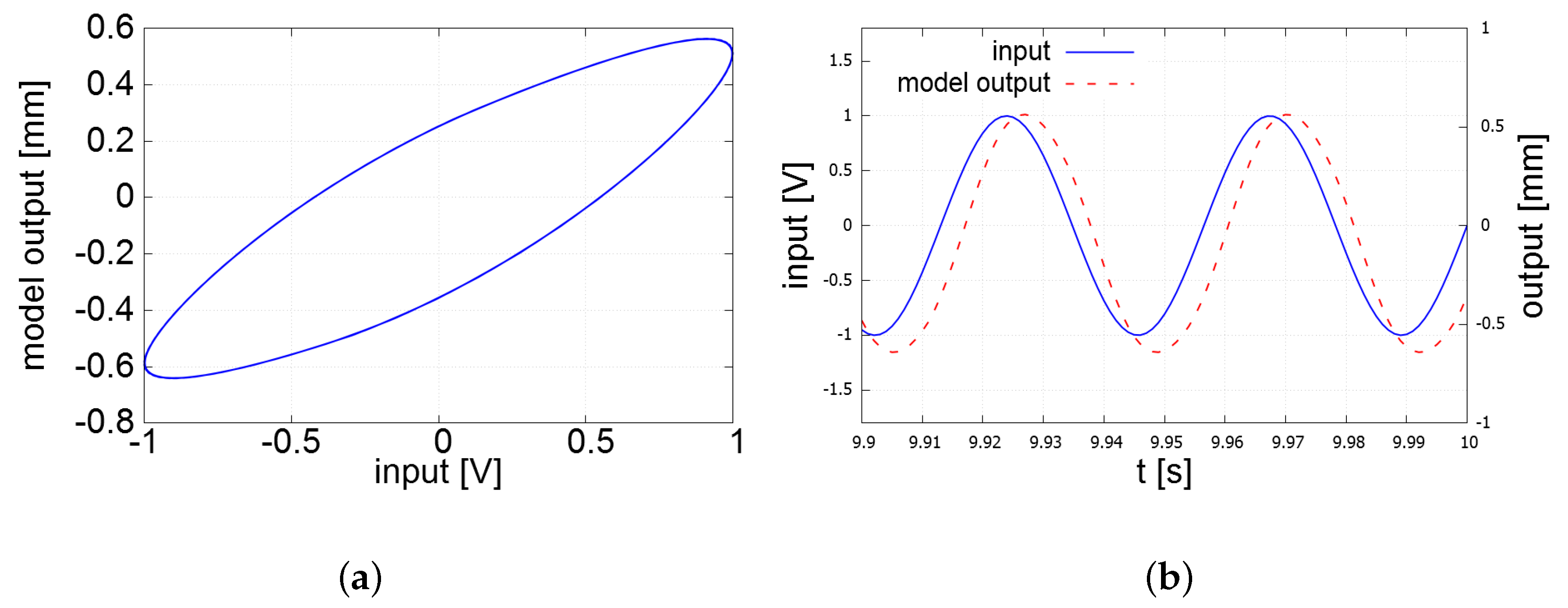
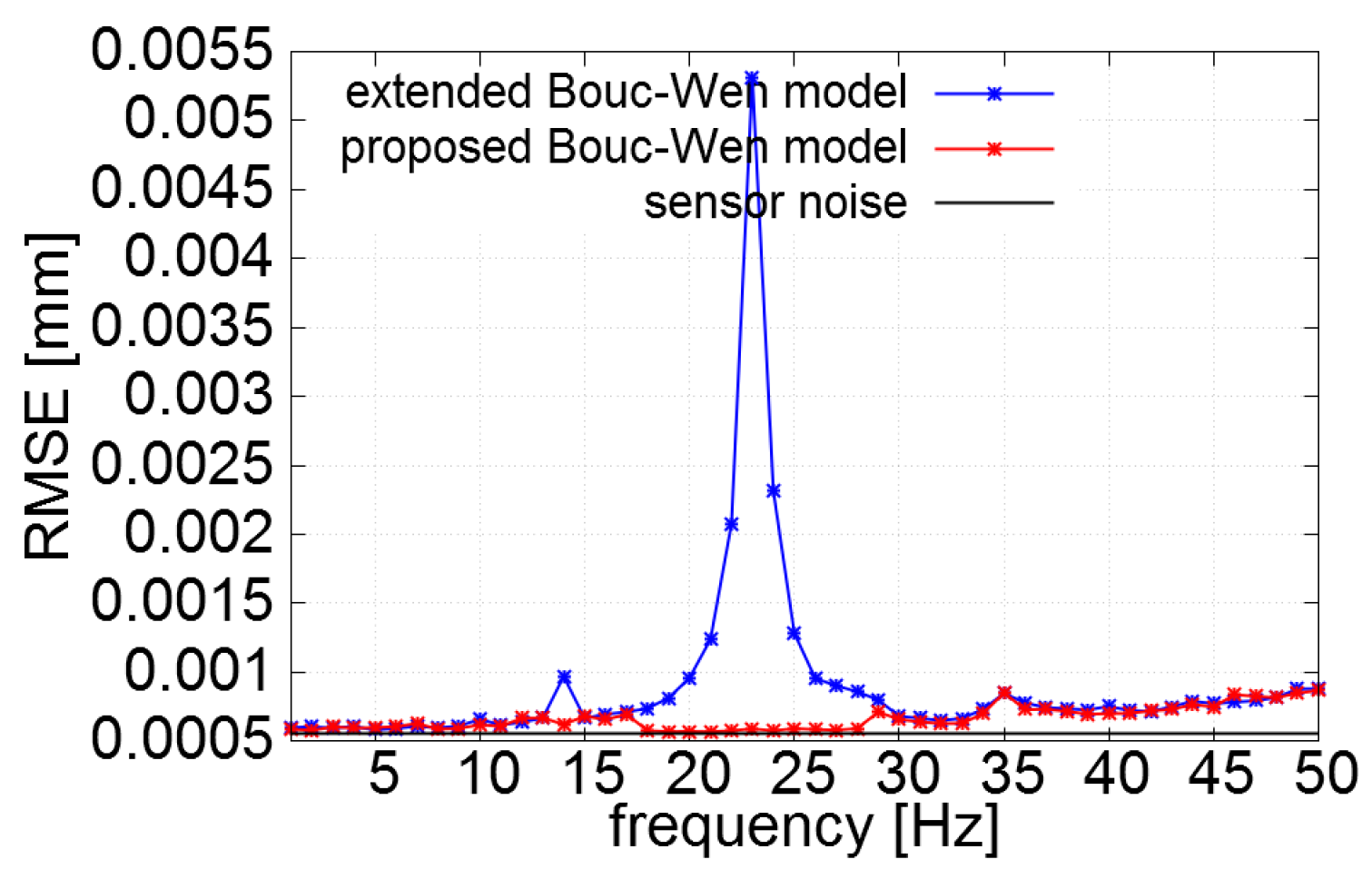
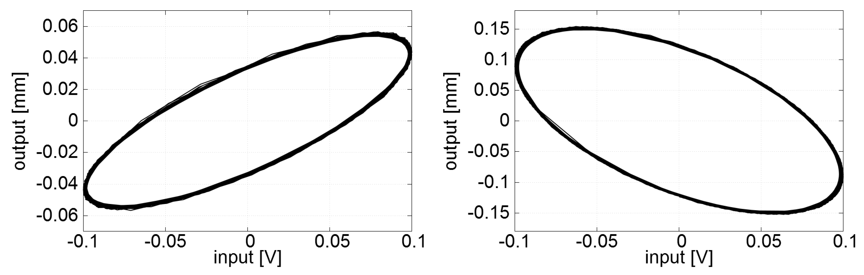
Figure 10 shows that the extended Bouc–Wen model produced a large modeling error at the frequency where odd harmonic oscillation was observed, whereas the error was eliminated when the proposed enhanced Bouc–Wen model was applied. 
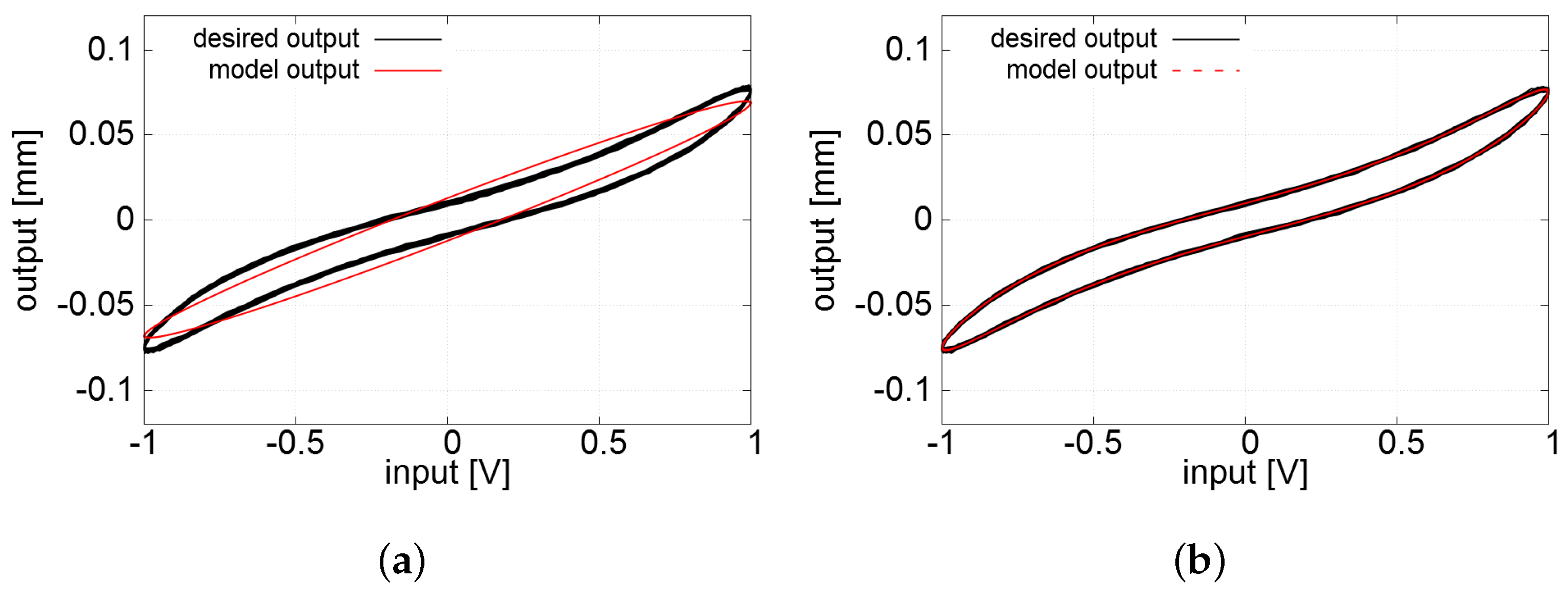
Figure 11 shows the hysteresis loops calculated with the extended Bouc–Wen model and the proposed enhanced Bouc–Wen model (6). The modeling precision attained with the proposed enhanced Bouc–Wen model with the third harmonic component was much better than that with the extended Bouc–Wen model.
Figure 10.
The RMS modeling errors as a function of the input frequency.
Figure 11.
The model outputs and the measurement of the actuator displacement to the 23 Hz sinusoidal input. The proposed enhanced Bouc–Wen model (6) shows good accuracy, whereas the previous extended Bouc–Wen model fails to capture the twisted shape of the hysteresis loop. (a) Result with the extended Bouc–Wen model in []; (b) Result with the enhanced Bouc–Wen model (6).
4. Compensation of Hysteresis Nonlinearity and Attenuation of Odd Harmonic Oscillation with the Enhanced Bouc–Wen model
We employed a two-stage thinking strategy to synthesize a controller which not only compensates hysteresis but also attenuates the odd harmonic. The final form of the proposed controller should be classified as a FF + FB architecture as mentioned in the introduction, but the usage of feedback is indirect. We first derive a hysteresis compensation control input based on the direct inverse using the first two equations of the enhanced Bouc–Wen model (6) and (7). We then synthesize an additional control input or which amounts to the source of odd harmonic oscillation and subtract it from , intending to cancel the source of odd harmonic oscillation. The details are given below.
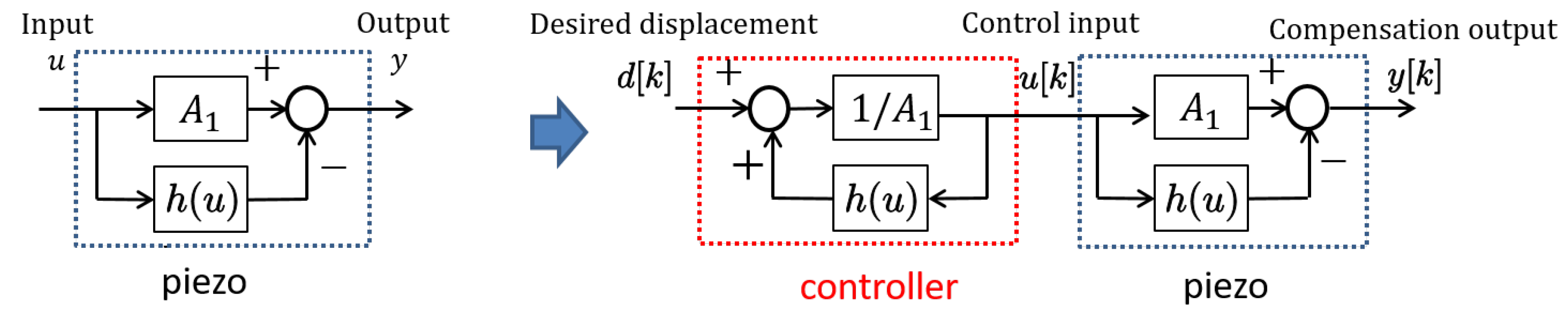
We start from the derivation of the hysteresis compensation input . It is based on the idea referred to as the direct inverse multiplication proposed by Rakotondrabe [] which is schematically described by a block diagram in Figure 12.
Figure 12.
The direct inverse multiplication proposed by Rakotondrabe [].
If the output of the model is identically equal to the desired output d, a simple algebraic manipulation of (1) leads to the control law
Following the same line, we replace the output terms , with their desired values , and in the second equation of (3) to have
where denotes the synthesized control input at the k-th sampling interval. However, the control law (15) is not feasible in its current form, as it includes , and the calculation of in the first equation of (3) requires . We thus need further algebraic manipulation of the equation. Introducing the first equation of (3) to (15) while carefully handling the absolute-valued terms included in the equation, we have
as the control law when , or
as the control law when . These two formulas of the control law can be calculated with the identified model parameters without having causality-related issues.
The control input does not take odd harmonics into account. The tracking error between the desired response and the actuator output with this control input might be governed by the odd harmonics. 
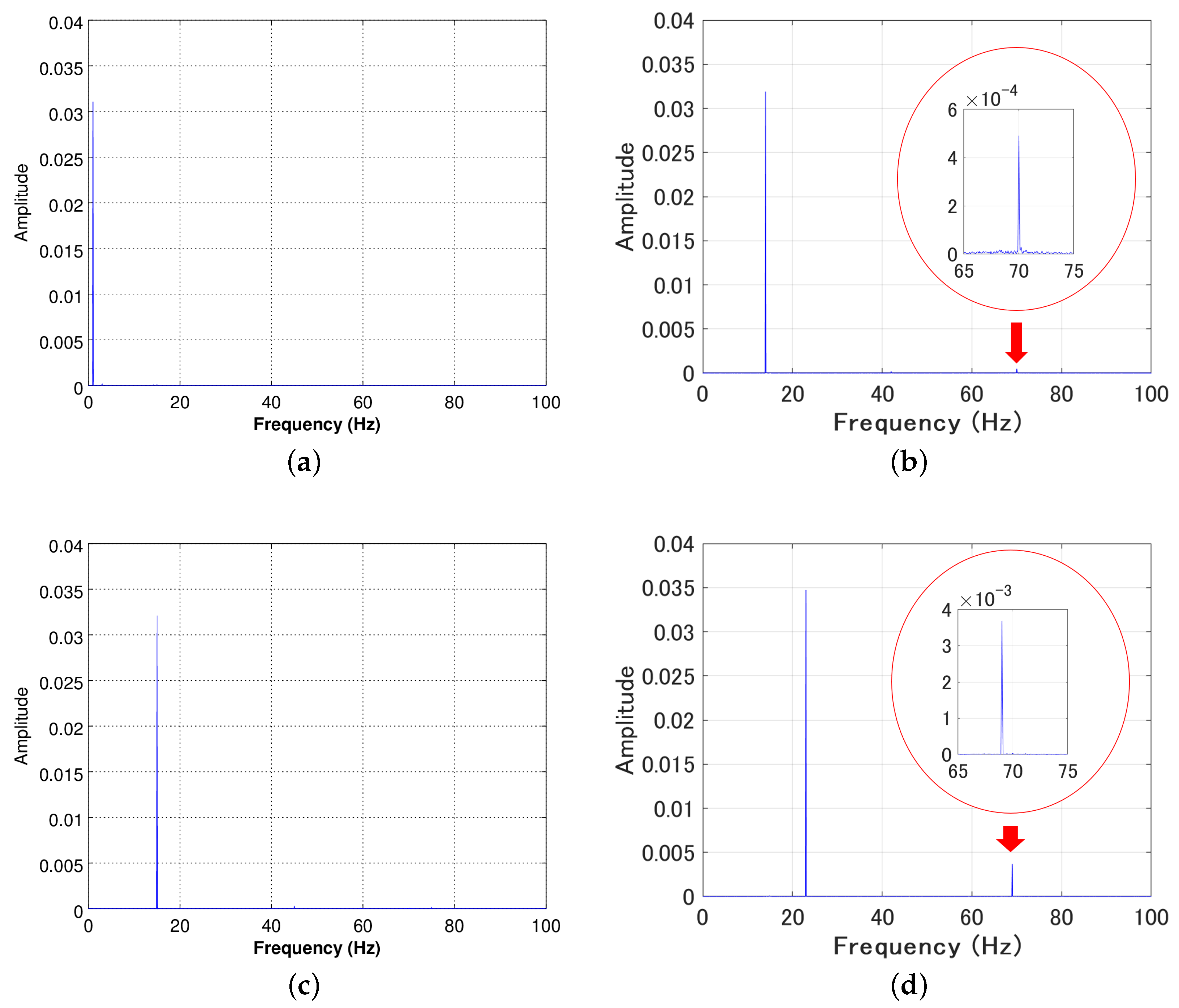
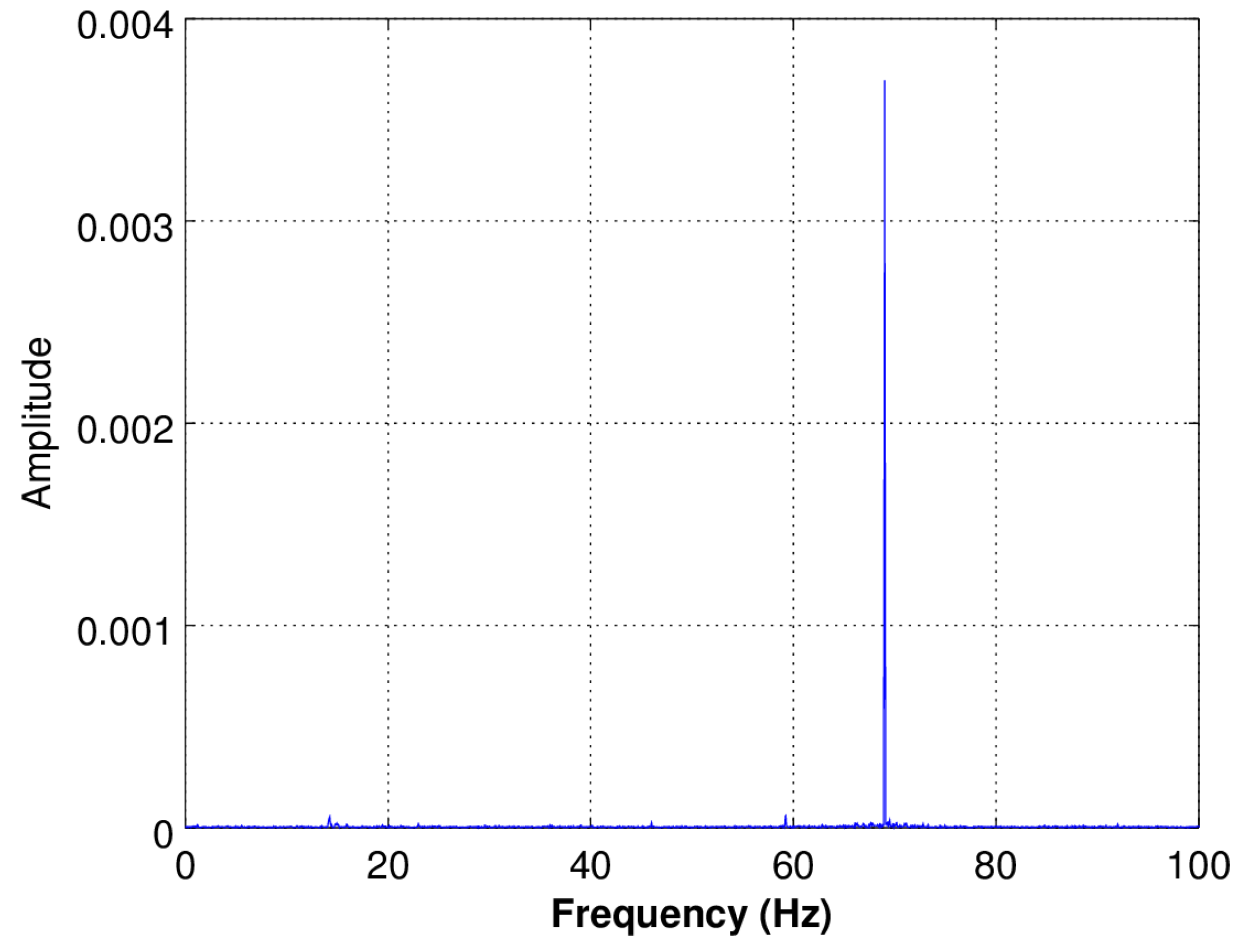
Figure 13 shows the result of FFT analysis of the tracking error signal when the 23 Hz sinusoidal reference signal is given. The actuator is controlled by the inputs calculated by (16) and (17). It can be seen from the figure that the error is governed by the third harmonic of the input. Thus, it is natural to infer that the actuator motion in this kind of situation can be explained numerically by the third equation defining or of the proposed enhanced Bouc–Wen model (6) or (7). However, since we conducted the parameter identification experiment using a pure sinusoidal input signal, the identified or cannot be used to attenuate the harmonic since the phase and the amplitude of the third/fifth harmonic oscillation of the actuator under the control by would be different from the values observed with pure sinusoidal inputs.
Figure 13.
The result of the FFT analysis of the tracking error for 23 Hz sinusoidal reference when the actuator is controlled only by . It is apparent that the error signal includes only the third harmonic component.
In principle, the control law synthesized here to attenuate the odd harmonic oscillation is close to the technique known as ZV input shaping [], as the proposed input excites 180° out-of-phase odd harmonic oscillation with the tracking error signal to cancel it out. Let ( for fifth harmonic) denote the values of , which explain the behavior of the tracking error—the difference between and —governed by the third/fifth harmonic. These s can be determined by the RLS algorithm using the third equation of (6) or (7).
If we calculate the input signal by
for the third harmonic behavior when the third harmonic is present, or
for the fifth harmonic behavior when the fifth harmonic is present, the control law
for the reference frequency whose actuator response contains component, or
for the frequency whose actuator response contains component will compensate the hysteresis and attenuate the third/fifth harmonic when it is present. The entire block diagram of the control system proposed positioning tracking control system is given in Figure 14. The control input compensates both hysteresis and structural dynamics, and the additional input or attenuates the odd harmonic oscillation.
Figure 14.
Proposed hysteresis compensator with the third/fifth harmonics attenuation. RLS: recursive least square.
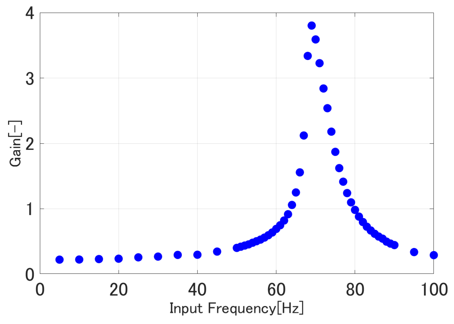
A short note should be given here about the implementation of the proposed control system. We will do the RLS calculation on-line to determine 
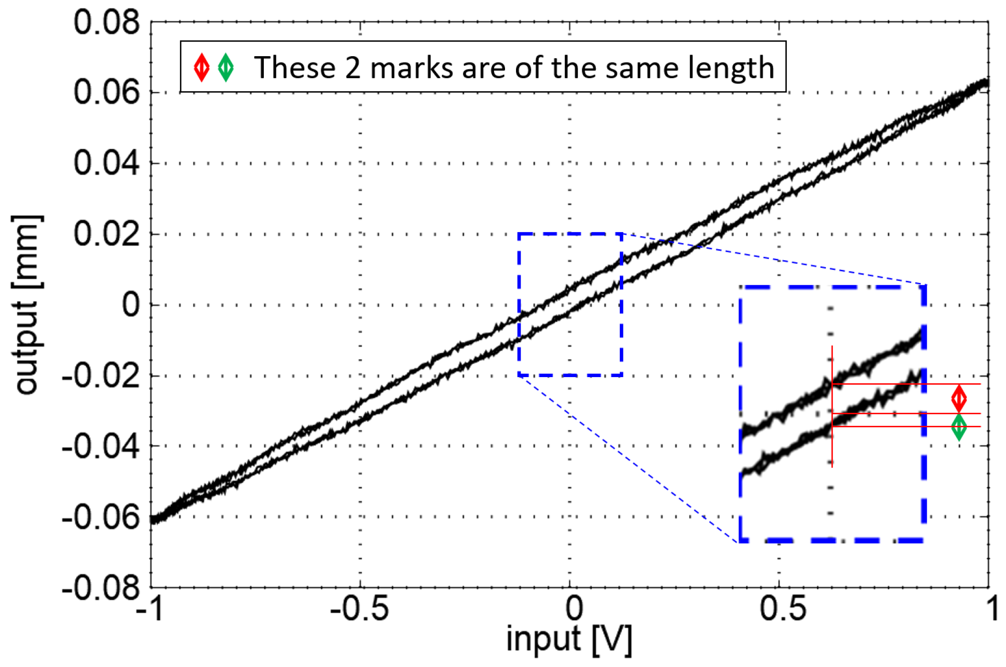
in the control law using the measured tracking error. However, because of the physical characteristics of the actuator used in this study (as shown in Figure 15), we calculated the tracking error used in the RLS calculation by
for the reference frequencies between 18 and 22 Hz where third harmonic is present but is smaller than or equal to 66 Hz, whereas we use the definition
for the reference frequencies of 14 and 23 to 26 Hz whose fifth or third harmonic exceeds 66 Hz.
Figure 15.
Hysteresis loops of the actuator for (a) 66 Hz and (b) 69 Hz input sinusoids. Loop (a) is a commonly observed loop whereas the polarity is inverted in loop (b).
5. Compensation Experiment
A hysteresis compensation experiment was conducted with the thin bimorph piezoelectric actuator to show the validity of the proposed compensator. Results obtained with the controller synthesized with the extended Bouc–Wen model hence discarding the odd harmonic oscillation are also shown here for comparison.
Let the desired output be defined by
where represents the amplitude of the desired trajectory and f is the driving frequency which was altered from 1 Hz to 50 Hz with 1 Hz increment. The quantity is determined by
for each f using the input sequence and the corresponding output measurement both obtained in the identification experiment, where m is the number of data points used for calculation. Root mean squared compensation error was calculated for every frequency attempt using the data collected after 20 s from the start of the control attempt to exclude the transient response from compensation performance calculation.
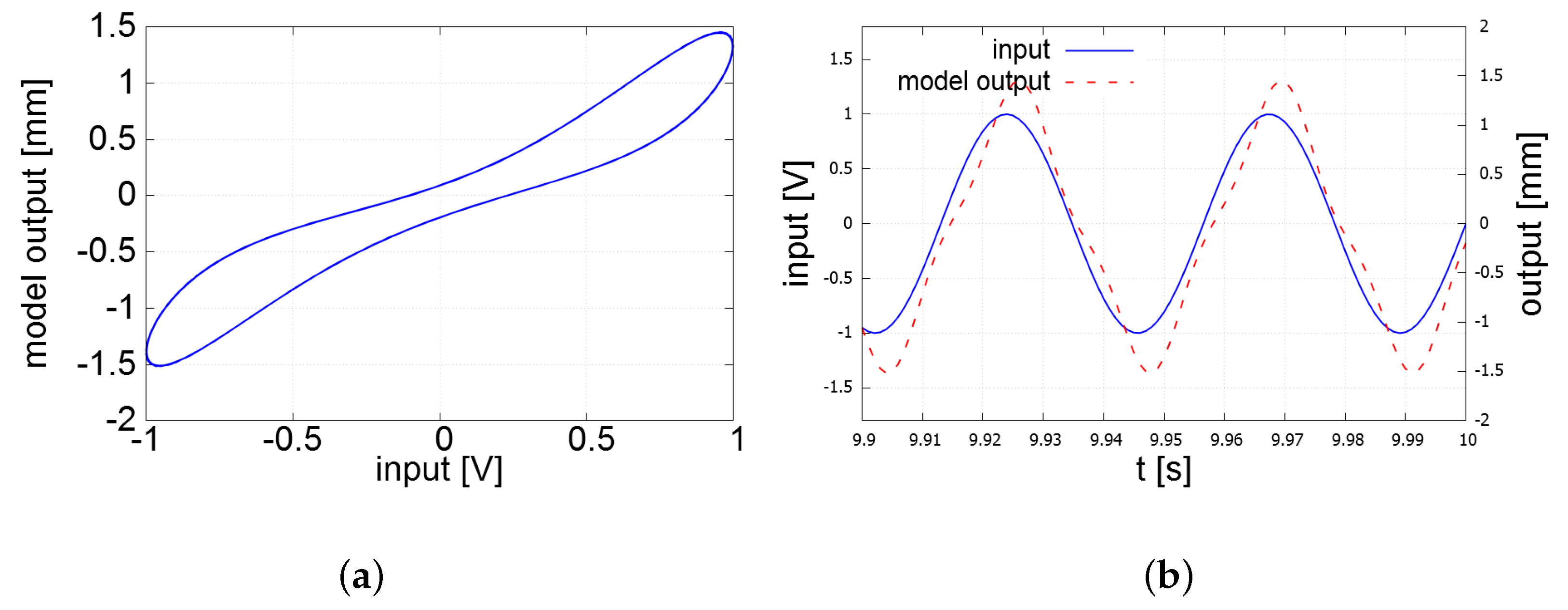
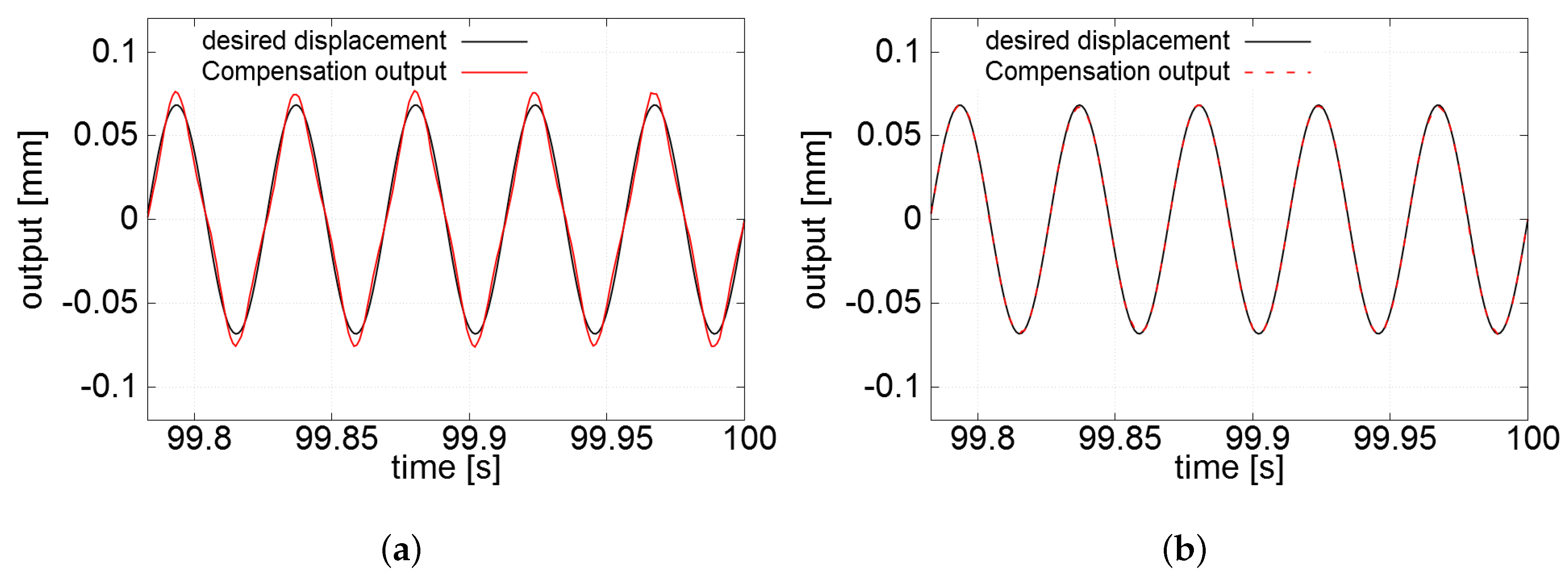
Figure 16 shows the root mean squared error (RMSE) values of the tracking control. The proposed hysteresis compensation with the third/fifth harmonic attenuation clearly outperformed the controller based on the extended Bouc–Wen model, which does not consider the third/fifth harmonics. 
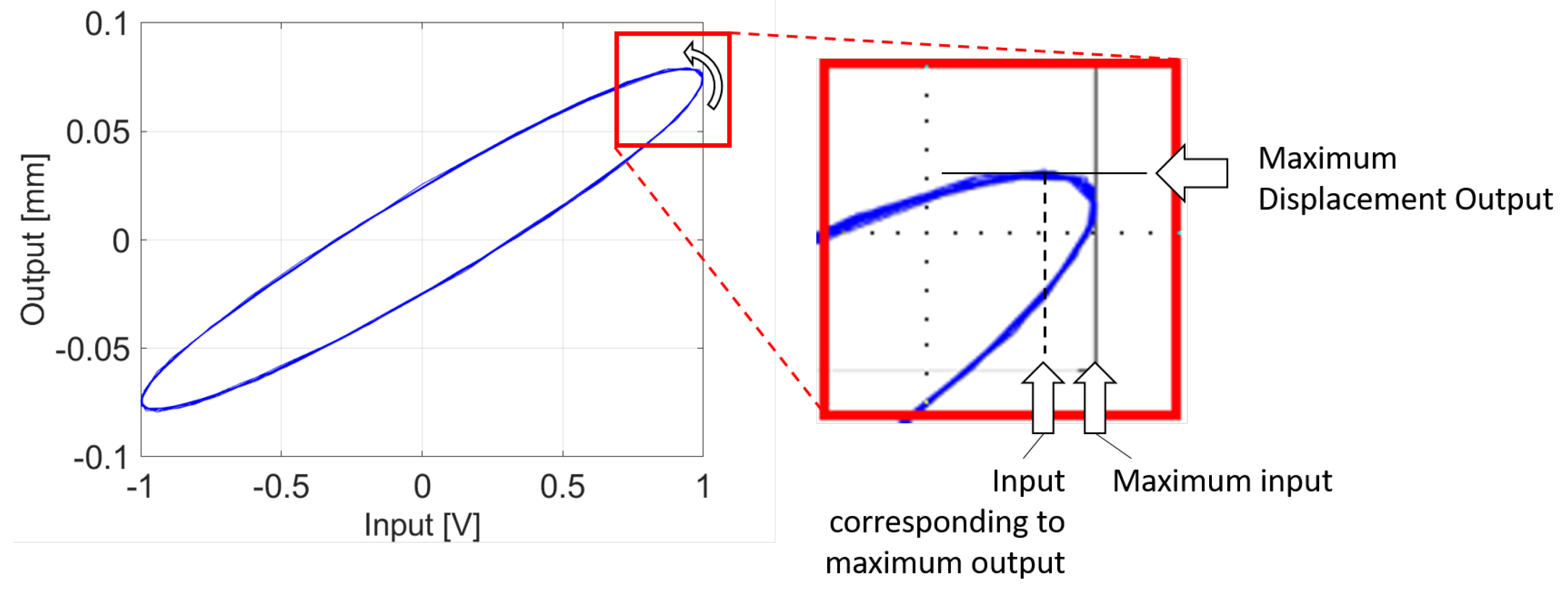
Figure 17 shows the result of the tracking control to the 23 Hz reference in time domain. High precision tracking was achieved with the proposed controller shown in Figure 17b, whereas moderate tracking error remains in Figure 17a.
Figure 16.
The root mean squared error (RMSE) of compensation as a function of the input frequency.
Figure 17.
Time domain comparison of the output displacement of the piezoelectric actuator and the reference trajectory. (a) Result of compensation for 23 Hz input: control input is synthesized with only (16) and (17); (b) Result of compensation for 23 Hz input: control input is synthesized with the proposed control law (20).
6. Conclusions
An enhanced Bouc–Wen model to capture the odd harmonic oscillation caused by the hysteresis nonlinearity of a bimorph-type piezoelectric actuator is proposed in this paper. The model provides high modeling accuracy for frequency-dependent hysteresis nonlinearity which also exhibits the third/fifth harmonic oscillation. We also propose a hysteresis compensator based on the proposed enhanced Bouc–Wen model which also attenuates the third/fifth harmonic oscillation. The results of the tracking control experiment with a pure sinusoidal reference whose frequency ranged between 1 and 50 Hz proved the excellent performance of the proposed control system.
Author Contributions
Conceptualization, F.F. and K.T.; Methodology, F.F. and K.T.; Software, K.T.; Validation, F.F. and K.T.; Formal Analysis, K.T.; Investigation, K.T.; Resources, F.F. and T.S.; Data Curation, K.T., K.M. and T.S.; Writing—Original Draft Preparation, F.F. and K.T.; Writing—Review & Editing, F.F.; Visualization, K.T.; Supervision, F.F.; Project Administration, F.F.; Funding Acquisition, F.F.
Funding
This research received no external funding.
Conflicts of Interest
The authors declare no conflict of interest.
References
- Yong, Y.K.; Bhikkaji, B.; Moheimani, S.O.R.R. Design, Modeling, and FPAA-Based Control of a High-Speed Atomic Force Microscope Nanopositioner. IEEE/ASME Trans. Mechatron. 2013, 18, 1060–1071. [Google Scholar] [CrossRef]
- Rahman, M.A.; Mamun, A.A.; Yao, K. Rate dependent direct inverse hysteresis compensation of piezoelectric micro-actuator used in dual-stage hard disk drive head positioning system. Rev. Sci. Instrum. 2015, 86, 085002. [Google Scholar] [CrossRef] [PubMed]
- Karpelson, M.; Wei, G.Y.; Wood, R.J. Driving high voltage piezoelectric actuators in microrobotic applications. Sens. Actuators A Phys. 2012, 176, 78–89. [Google Scholar] [CrossRef]
- Ueda, Y.; Fujii, F.; Liu, D. Identification of hysteresis using adaptive Preisach model. Trans. JSME 2015, 81. (In Japanese) [Google Scholar] [CrossRef]
- Yu, Y.; Xiao, Z.; Naganathan, N.; Dukkipati, R. Dynamic preisach modelling of hysteresis for the piezoceramic actuator system. Mech. Mach. Theory 2002, 37, 75–89. [Google Scholar] [CrossRef]
- Janaideh, M.A.; Rakheja, S.; Su, C.Y. Experimental characterization and modeling of rate-dependent hysteresis of a piezoceramic actuator. Mechatronics 2009, 19, 656–670. [Google Scholar] [CrossRef]
- Li, Y.; Xiao, S. Dynamic compensationand H∞ control for piezoelectric actuators based on the inverse Bouc-Wen model. Robot. Comput.-Integr. Manuf. 2014, 30, 47–54. [Google Scholar]
- Rakotondrabe, M. Bouc-wen modeling and inverse multiplicative structure to compensate hysteresis nonlinearity in piezoelectric actuators. IEEE Trans. Autom. Sci. Eng. 2011, 8, 428–431. [Google Scholar] [CrossRef]
- Tatebatake, K.; Fujii, F. The extended bouc-wen model with structural element and its application to the compensation of ratedependent hysteresis of a piezoelectric actuator. In Proceedings of the 2017 IEEE/SICE International Symposium on System Integration (SII), Taipei, Taiwan, 11–14 December 2017; pp. 644–650. [Google Scholar]
- Habineza, D.; Rakotondrabe, M.; Gorrec, Y.L. Multivariable generalized bouc-wen modeling, identification and feedforward control and its application to multi-dof piezoelectric actuators. IFAC Proc. Vol. 2014, 47, 10952–10958. [Google Scholar] [CrossRef]
- Li, C.X.; Gu, G.Y.; Zhu, L.M.; Su, C.Y. Odd-harmonic repetitive control for high-speed raster scanning of piezo-actuated nanopositioning stages with hysteresis nonlinearity. Sens. Actuators A Phys. 2016, 244, 95–105. [Google Scholar] [CrossRef]
- Gu, G.Y.; Zhu, L.M.; Su, C.Y.; Ding, H.; Fatikow, S. Modeling and Control of Piezo-Actuated Nanopositioning Stages: A Survey. IEEE Trans. Autom. Sci. Eng. 2016, 13, 313–332. [Google Scholar] [CrossRef]
- Xu, Q.; Li, Y. Modeling and Control of Rate-Dependent Hysteresis for a Piezo-Driven Micropositioning Stage. In Proceedings of the 2011 IEEE International Conference on Robotics and Automation, Shanghai, China, 9–13 May 2011; pp. 1670–1675. [Google Scholar]
- Li, L.; Li, C.X.; Gu, G.; Zhu, L.M. Positive acceleration, velocity and position feedback based damping control approach for piezo-actuated nanopositioning stages. Mechatronics 2017, 47, 97–104. [Google Scholar] [CrossRef]
- Rakotondrabe, M.; Clévy, C.; Lutz, P. Complete Open Loop Control of Hysteretic, Creeped, and Oscillating Piezoelectric Cantilevers. IEEE Trans. Autom. Sci. Eng. 2010, 7, 440–450. [Google Scholar] [CrossRef]
- Rakotondrabe, M.; Rabenorosoa, K.; Agnus, J.; Chaillet, N. Robust Feedforward-Feedback Control of a Nonlinear and Oscillating 2-DOF Piezocantilever. IEEE Trans. Autom. Sci. Eng. 2011, 8, 506–519. [Google Scholar] [CrossRef]
- Singer, N.C.; Seering, W.P.; Pasch, K.A. Shaping Command Inputs to Minimize Unwanted Dynamics. U.S. Patent 4,916,635, 10 April 1990. [Google Scholar]
- Wen, Y.K. Method for random vibration of hysteretic systems. ASCE J. Eng. Mech. Div. 1976, 102, 249–263. [Google Scholar]
- Low, T.S.; Guo, W. Modeling of a Three-Layer Piezoelectric Bimorph Beam with Hysteresis. J. Microelectromech. Syt. 1995, 4, 230–237. [Google Scholar] [CrossRef]
- Ismail, M.; Ikhouane, F.; Rodellar, J. The Hysteresis Bouc-Wen Model, a Survey. Arch. Comput. Methods Eng. 2009, 16, 161–188. [Google Scholar] [CrossRef]
- Song, J.; Kiureghian, A.D. Generalized bouc-wen model for highly asymmetric hysteresis. J. Eng. Mech. 2006, 132, 610–618. [Google Scholar] [CrossRef]
© 2018 by the authors. Licensee MDPI, Basel, Switzerland. This article is an open access article distributed under the terms and conditions of the Creative Commons Attribution (CC BY) license (http://creativecommons.org/licenses/by/4.0/).