1. Introduction
Robotic system design, control synthesis, and validation rely heavily on simulation [
1,
2]. In dynamic mobile robots and manipulators, simulation environments enable evaluating actuator torque requirements [
3], thermal and electrical constraints [
4], and structural loads [
5] prior to physical prototyping. Simulation platforms are also widely used to train control policies via reinforcement learning for direct deployment onto hardware [
6,
7,
8].
However, transferring control policies from simulation to physical hardware remains difficult due to the simulation-to-reality (sim-to-real) gap [
9]. A key source of this discrepancy is the simplified modeling of joint-level actuator dynamics [
10]. Physics engines such as MuJoCo 3.3.1 or PyBullet 3.2.7 typically represent joints as ideal PD torque sources, ignoring Field-Oriented Control (FOC) loops, current limits, winding inductance, back-EMF, and sensor quantization [
11,
12]. As shown in
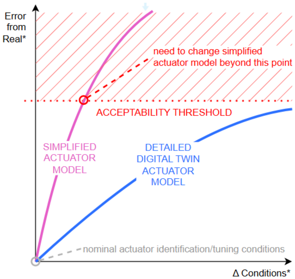
Figure 1, while ideal joint models can match baseline step responses under nominal conditions, their predictive accuracy drops when control gains, payloads, or trajectory dynamics vary, often causing unexpected torque saturation or instability on real hardware.
In this work, predictive simulation refers to predicting the actuator response before executing the corresponding physical experiment. Specifically, the quantities of interest are joint position and actuator torque. The precise inputs, mathematical formulation, and evaluation procedure are defined in
Section 2.3.
Several approaches can be used to improve agreement between simulation and physical hardware. Simplified actuator models can be identified from experimental trajectories, while modeling uncertainty can be addressed through parameter randomization or data-driven actuator models [
6,
7]. However, a model identified around a restricted operating condition may require retuning when controller gains, payload, or motion dynamics change. Data-driven representations may additionally depend on the operating conditions covered by their training data. These limitations motivate actuator representations that preserve the relevant physical dynamics and reproduce the interfaces and control architecture of the physical device.
Digital Twins have been investigated in robotics for system supervision, virtual commissioning, collaborative robotics, Hardware-in-the-Loop testing, and virtual-to-physical interaction [
10,
13,
14,
15]. However, the term Digital Twin is used with different meanings across the literature. To avoid using it as a generic label for a detailed simulation model, this work adopts an explicit actuator-level definition.
In this paper, the term actuator Digital Twin refers to an actuator-specific executable model that reproduces the relevant electromechanical dynamics, operating limits, sensing interfaces, and embedded control architecture of the physical device. The detailed criteria used to distinguish the AUGUR DT from a generic high-fidelity actuator model are provided in
Section 2.1. Although AUGUR supports Hardware-in-the-Loop operation, the experiments reported here use the model offline.
The central research question is whether this actuator-level Digital Twin can predict joint position and actuator torque more consistently than a conventional simplified model when trajectory dynamics, mechanical load, and controller gains are varied, while remaining computationally suitable for integration into multi-joint robotic systems.
To address this question, we evaluate the PULSAR AUGUR Digital Twin of the PULSE115 quasi-direct-drive actuator [
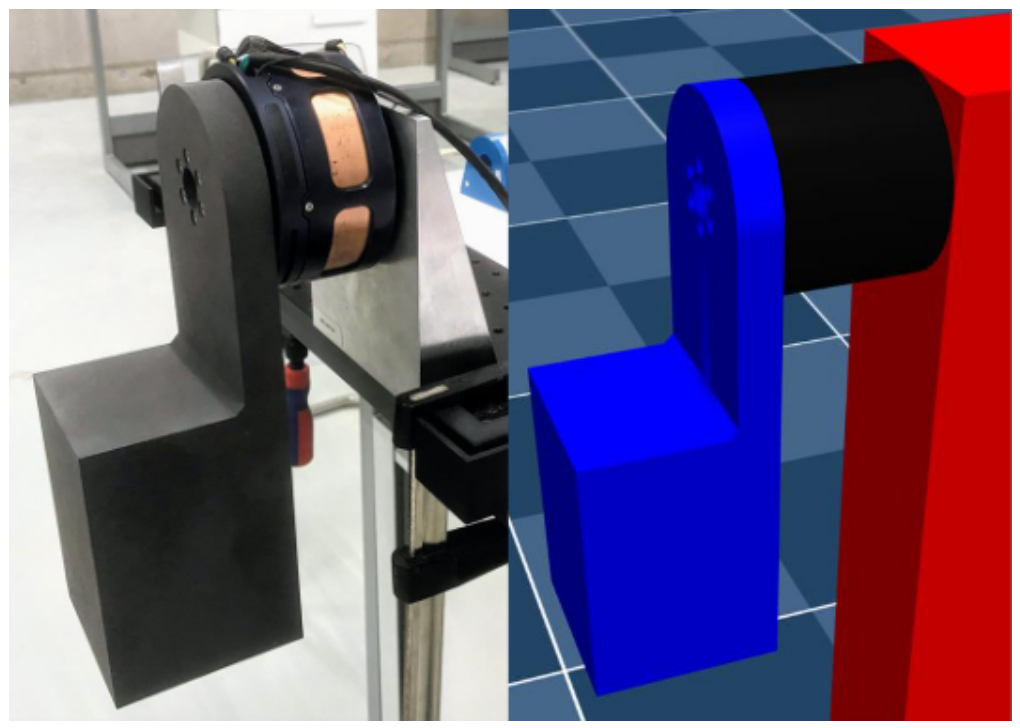
16]. Experimental validation is based on the single-degree-of-freedom pendulum shown in
Figure 2. The corresponding mechanical system is reproduced in simulation, allowing measured and simulated actuator responses to be compared under identical reference trajectories and mechanical configurations.
The evaluation is performed in two stages. First, measurements from the physical pendulum are compared with simulations using AUGUR in MuJoCo 3.3.1 and Simulink R2024b and with the conventional MuJoCo actuator model. The experiments cover ramp and step trajectories, configurations with and without the mechanical link, and different gain settings for the simplified model. Second, four instances of the actuator DT are integrated into a simulated four-degree-of-freedom humanoid arm to evaluate multi-actuator integration and computational performance. This second experiment addresses scalability and does not constitute the physical validation of prediction accuracy at the complete arm level.
The main contributions of this work are:
An explicit actuator-level Digital Twin formulation combining SPMSM electromechanical dynamics, physical operating limits, sensing characteristics, and the embedded cascaded control architecture of a specific quasi-direct-drive actuator.
An operational definition and experimental evaluation of predictive simulation based on forward prediction of joint position and actuator torque.
An experimental comparison between the actuator DT and a conventional simplified actuator model across different trajectory dynamics, mechanical loads, and controller gains.
Cross-platform evaluation of the same actuator DT in MuJoCo and Simulink using physical actuator measurements as the common reference.
Demonstration of four simultaneous actuator DT instances in a four-degree-of-freedom robotic arm simulation, including a computation-time benchmark showing approximately 6.3 times faster-than-real-time execution.
2. Methodology
2.1. Actuator Digital Twin Definition and Modeling Framework
To model actuator behavior, we evaluate two distinct paradigms: (i) a high-fidelity, physics-based DT and (ii) a conventional simplified model.
Digital Twins are generally understood as executable digital representations of physical assets that preserve correspondence with their physical counterparts through the representation of relevant physical processes and operational interfaces. Although the precise definition varies across application domains, actuator-level Digital Twins have been proposed for electric drives using this general principle [
17]. Accordingly, this work adopts the following operational definition.
For the purposes of this study, an actuator model is considered an actuator Digital Twin when it satisfies the following criteria:
It is associated with a specific physical actuator and is parameterized using physical specifications or experimentally identified parameters corresponding to that actuator.
It reproduces the relevant electromechanical dynamics that determine the actuator response, including motor electrical dynamics, mechanical dynamics, transmission effects, friction, and physical operating limits.
It implements the embedded control architecture and accepts the same command variables and controller parameters as the physical actuator.
It reproduces the relevant sensing interfaces and discrete execution characteristics of the physical device.
It exposes actuator-level command, state, and mechanical interfaces that allow integration into robot-level simulation and Hardware-in-the-Loop configurations.
The AUGUR model evaluated in this work satisfies these criteria for the PULSE115 actuator. Therefore, the term Digital Twin is used here according to these explicit actuator-level properties rather than as a generic label for a high-fidelity simulation model.
The proposed DT is constructed using a bottom-up physical modeling approach for Surface-Mounted Permanent Magnet Synchronous Motors (SPMSM). The electrical dynamics of the stator windings are expressed in the rotor-aligned synchronous
reference frame using the Park transformation:
where
and
represent the stator
d- and
q-axis voltages;
and
are the
d- and
q-axis currents;
is the stator winding resistance;
and
denote the
d- and
q-axis inductances;
is the permanent magnet flux linkage; and
is the electrical angular speed of the rotor. The electrical speed relates to the mechanical rotor velocity
by
where
P is the number of pole pairs.
The electromagnetic torque
generated by the motor is given by
For surface-mounted PMSMs,
, simplifying the electromagnetic torque expression to a linear relation with the quadrature current:
where
is the motor torque constant.
The mechanical rotational dynamics of the motor shaft, coupled to the gearbox and load, are governed by
where
J is the total moment of inertia of the rotor and internal couplings;
B is the viscous friction coefficient;
represents the external load torque;
is the rotor position; and
represents the nonlinear Coulomb friction
where
is the static Coulomb friction torque.
The physical parameters of the actuator were identified from experimental hardware logs following the parameter identification procedures presented by Pérez-Díaz et al. [
16].
Table 1 lists the complete physical, electrical, and mechanical specifications of the Pulsar PULSE115 quasi-direct-drive actuator used in this study.
This actuator-specific parameterization is one of the elements that distinguishes the AUGUR DT from a generic electromechanical motor model. The simulated response is generated using parameters associated with the same actuator type subsequently evaluated in the physical experiments.
Additionally, the DT emulates the physical actuator’s embedded controller firmware at a loop execution frequency of
(
), matching the exact sampling and computation rate of the physical micro-controller. The controller operates as a cascaded control loop (
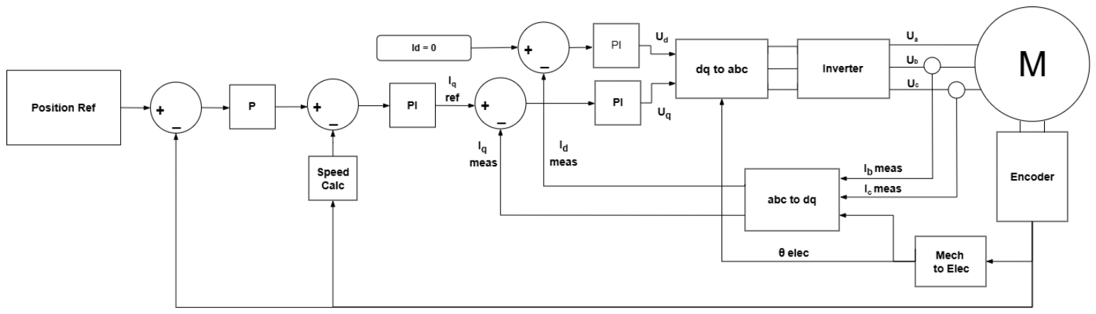
Figure 3) consisting of an outer proportional (P) position controller, an intermediate proportional–integral (PI) velocity controller, and an inner PI current controller running FOC. The DT is written in C and compiled into native code, executing the
FOC and cascaded control loops on CPU without requiring GPU acceleration. This provides fast execution (
real-time) alongside low-level physical accuracy on standard hardware.
The same controller parameters and reference variables can therefore be applied to the simulated and physical actuator without replacing the embedded control architecture with an abstract equivalent controller.
By combining physical SPMSM electromechanical modeling with low-level firmware emulation, the DT explicitly incorporates key actuator-level features (items 1–4), while accounting for unmodeled physical boundary factors (item 5) that contribute to the sim-to-real gap:
Actuator Nonlinearities (Modeled): Current saturation limits (), DC bus voltage clipping (), back-EMF velocity coupling, and torque constant non-idealities.
Friction and Transmission Effects (Modeled): Viscous friction (), Coulomb static friction (), and planetary gearbox reduction ratio (5:1). Gearbox backlash of is unmodeled in the DT’s mechanical coupling, serving as a secondary physical discrepancy factor during high-speed, unloaded motion.
Sensor Noise and Quantization (Modeled): Dual absolute magnetic encoders measuring input/output shaft angles, and discrete setpoint streaming update boundaries.
Embedded Controller Dynamics (Modeled): Internal FOC current loop regulation, velocity PI dynamics, and current saturation anti-windup.
Environmental and Structural Compliance (Unmodeled): Structural compliance of the mounting table and mechanical base vibrations during rapid step transients are omitted in the simulation, constituting a physical boundary discrepancy between hardware and simulation.
The distinction between modeled and unmodeled effects is important for interpreting the prediction results. The DT is not assumed to reproduce every physical phenomenon affecting the actuator, and prediction errors may therefore remain when unmodeled effects become significant.
In contrast, the simplified model (such as the standard actuator model native to the MuJoCo physics engine [
18]) uses ideal actuator dynamics and relies on abstract gain tuning. It assumes that joint torque is directly proportional to tracking error via PD gains, omitting internal current control, back-EMF, sensor noise, quantization, and friction:
where
and
are the control gains and
is the maximum output torque limit.
Unlike the AUGUR DT, this baseline does not reproduce the internal electrical states, embedded cascaded controller, sensing characteristics, or actuator-specific physical interfaces. It is therefore used as a conventional simplified actuator representation against which the predictive accuracy of the DT is evaluated.
2.2. Modular Integration Architecture
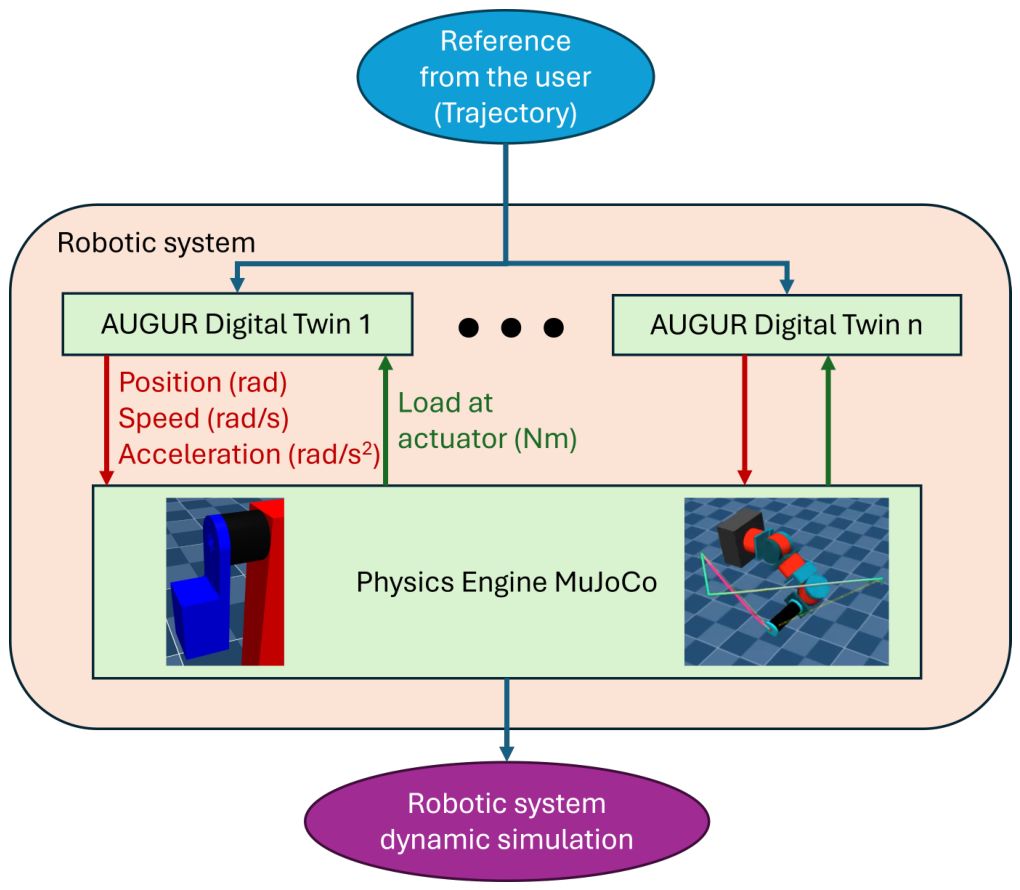
A key advantage of the proposed DT framework is its ability to simulate custom robotic systems with minimal integration effort. The general architecture used for integrating these models into multi-degree-of-freedom (multi-DOF) systems is illustrated in
Figure 4.
As shown, the integration process consists of three main requirements:
- 1.
A Unified Robot Description Format (URDF) describing the physical robot’s kinematics and rigid body dynamics.
- 2.
The connection of the actuator DTs to the physics engine (e.g., MuJoCo or Simulink Simscape) as custom actuator plugins or co-simulations, which read joint states and stream computed torque/force commands back to the engine.
- 3.
The provision of reference trajectories or control inputs.
This modular and scalable architecture enables the rapid deployment of high-fidelity simulations across a wide range of robotic platforms, supporting applications in design iteration, control development, and data-efficient learning.
In this study, multi-actuator integration is evaluated specifically using the simulated 4-DOF arm presented in the second case study.
2.3. Definition of the Predictive Simulation Task
The predictive task considered in this study is a deterministic forward simulation of the actuator response. For each experimental condition, the simulation receives the same prescribed joint-position reference, controller parameters, mechanical configuration, and initial state as the physical system.
The set of known experimental conditions can be represented as
where
is the prescribed joint-position trajectory,
contains the controller parameters,
describes the mechanical configuration, and
represents the initial state.
For a given actuator model
, the predictive simulation computes
where
is the predicted joint position and
is the predicted actuator torque.
The corresponding physical experiment provides the measured signals and . Prediction accuracy is evaluated by comparing the simulated and measured time histories under equivalent experimental conditions. This formulation defines the scope of prediction used throughout the remainder of the paper. Failure prognosis, remaining useful life estimation, predictive maintenance, and long-term parameter evolution are outside the scope of the present study.
2.4. Evaluation Metrics
To quantitatively assess the accuracy of the simulated actuator behavior at the joint level, we compute the Root Mean Square Error (RMSE) between the simulated and real joint positions and torques. This metric captures the average deviation over time and penalizes larger errors more heavily, making it suitable for evaluating dynamic tracking performance.
The position prediction RMSE is defined as
where
is the predicted joint position at sample
i,
is the corresponding measured position from the physical actuator, and
N is the total number of samples.
The torque prediction RMSE is defined analogously as
where
and
are the simulated and measured actuator torque values, respectively.
These metrics quantify actuator-response prediction error over each complete trajectory. They characterize predictive performance within the experimental domain considered in this study and do not imply prediction accuracy outside the tested trajectories, mechanical configurations, and controller parameters.
Furthermore, to evaluate the performance of the DT in a multi-DOF task-space control context, we adopt metrics derived from the ISO 9283:1998 standard [
19], which defines performance criteria for industrial robots.
These metrics are used only to characterize trajectory tracking within the simulated 4-DOF arm. Since no corresponding physical arm measurements are available, and are not interpreted as predictive sim-to-real errors.
Following the standard’s experimental methodology, the robot end-effector is programmed to follow a linear trajectory connecting sequential waypoints within its workspace. Positioning accuracy () is assessed after the robot reaches the target position, calculated by averaging the coordinate deviation over the final 1.0 s of the 2 s hold period to ensure transient oscillations have stabilized. Path accuracy () is monitored continuously during the active translation phases, computing the maximum geometric deviation from the reference linear segment:
Positioning Accuracy (): Measures the deviation between the actual and target end-effector positions after the robot reaches and stabilizes at a designated point. It is calculated during the hold phase:
where
denotes the commanded position and
is the actual stabilized end-effector position.
Path Accuracy (): Captures the maximum deviation from the desired path along the trajectory. It is defined as
where
are reference positions along the ideal path and
are measured end-effector positions.
3. Case Studies
The evaluation is organized into two complementary case studies. The first uses a physical single-degree-of-freedom (1-DOF) pendulum to assess actuator-level predictive accuracy by comparing simulated and measured responses. The second uses a simulated four-degree-of-freedom (4-DOF) humanoid arm to evaluate multi-actuator integration and computational performance.
3.1. Actuator Platform: Pulsar PULSE115 and AUGUR
The experiments use the PULSE115 quasi-direct-drive actuator and its AUGUR actuator Digital Twin [
16]. AUGUR is evaluated according to the actuator-level Digital Twin criteria defined in
Section 2.1. In the experiments reported here, AUGUR is executed offline for the forward simulation of actuator behavior. The framework also supports Hardware-in-the-Loop operation, but this capability is not used in the present validation.
3.2. 1-DOF Pendulum Setup and Experimental Protocol
The first case study focuses on the 1-DOF pendulum shown in
Figure 2. The testbed comprises a physical experimental setup and its simulated counterpart. The physical setup consists of a Pulsar PULSE115 quasi-direct-drive actuator mounted on an aluminum support block, with a 3D-printed load link of 1.7 kg, manufactured in SLS resin, attached directly to the actuator output flange. In simulation, the link geometry, mass distribution, and inertia are reproduced from the CAD model, while the support is modeled as a rigid ground boundary.
This case study provides the physical validation of the predictive simulation task defined in
Section 2.3, because the simulated joint-position and actuator-torque responses are compared directly with signals obtained from the physical actuator under equivalent reference trajectories and mechanical configurations.
The physical system is compared with the following simulation configurations:
Real Hardware: Ground-truth position is measured using the 20-bit absolute encoder. Motor telemetry, including position, current, and torque-related signals, is streamed and logged using a Speedgoat real-time target machine at 10 kHz.
Simulink Simscape Multibody with AUGUR DT: The pendulum rigid-body model is reproduced from the URDF, while AUGUR is executed as a custom co-simulation block representing the actuator dynamics and embedded control.
MuJoCo with AUGUR DT: The same pendulum model is simulated in MuJoCo, using AUGUR as a custom actuator plugin.
MuJoCo with Standard Model: The pendulum is simulated in MuJoCo using the simplified native actuator representation described in
Section 2.1 as the baseline model.
The same reference trajectories and mechanical configurations are applied to the physical actuator and to the corresponding simulations to ensure that the resulting time histories can be compared directly.
All configurations are operated in position-control mode. Precomputed joint-position references are streamed at 100 Hz, while the internal actuator control loops operate at 10 kHz.
The control gains are configured as follows:
The AUGUR DT and the physical actuator use the same position-control gains. These gains were tuned in Simulink to obtain an approximately critically damped step response.
The MuJoCo Standard Model uses nominal gains of and , obtained by minimizing the mean-squared error with respect to the physical actuator response for a 90° step input. To evaluate sensitivity to the simplified-model stiffness, these nominal gains are additionally scaled by factors of 10 and 100, denoted as the medium-gain and high-gain configurations, respectively.
The 90° step condition therefore defines the tuning condition for the nominal simplified baseline. The remaining trajectories, load configurations, and gain scalings are used to evaluate how the same simplified actuator representation behaves when the operating condition departs from that tuning point.
The experimental protocol evaluates position and torque discrepancies under two trajectory families and two mechanical configurations, with and without the external link attached:
Multi-Ramp Trajectory: Motion from 0° to 90° and back, with transition durations of 0.5 s, 1 s, 4 s, and 10 s and a 2 s hold at each limit. The reference profile is generated using cubic spline interpolation to provide continuous velocity and acceleration profiles.
Multi-Step Trajectory: A sequence of position steps at 0°, 90°, 180°, 270°, 360°, 540°, and 720°, with each value held for 2 s. The command changes at the 100 Hz streaming boundary without rate limiting, producing high-dynamic transients that exercise the actuator current limits and closed-loop bandwidth.
All simulation environments are configured with a fixed step size of ms, corresponding to 10 kHz, to match the execution frequency of the physical embedded controller and the AUGUR inner loops. Simulink uses a fixed-step Runge–Kutta solver, whereas MuJoCo uses its standard semi-implicit Euler integration scheme.
The absolute magnetic joint encoder has a resolution of 20 bits, corresponding to a position quantization on the order of rad, which is substantially smaller than the position errors evaluated in this study. Laboratory temperature was maintained at approximately 22 °C during the experiments to reduce temperature-induced variation in winding resistance and actuator characteristics.
No structural compliance or vibration model is included in the simulated mounting boundary. Differences between this rigid simulated boundary and the physical support are therefore retained as part of the experimental sim-to-real discrepancy.
3.3. Simulated 4-DOF Humanoid Arm Setup
To evaluate multi-actuator integration and computational feasibility, four instances of the AUGUR DT are integrated into a simulated 4-DOF humanoid arm in MuJoCo. The arm consists of a 3-DOF shoulder and a 1-DOF elbow.
Because no corresponding physical humanoid arm is available in this study, this case study does not provide an additional measurement of physical predictive accuracy. Its purpose is to evaluate whether multiple actuator DT instances can be integrated into a coupled multi-joint simulation while maintaining practical computation time.
The arm follows a linear task-space trajectory between two waypoints. Each cycle consists of a forward segment of duration T, a 2 s hold, a return segment of duration T, and a second 2 s hold. The trajectory duration is varied across s, 1 s, 4 s, and 10 s.
Joint references are computed through inverse kinematics and streamed to the four actuators at 100 Hz. The MuJoCo simulation uses a fixed step size of ms.
Task-space tracking is characterized using the path and positioning metrics introduced in the Evaluation Metrics subsection. For the positioning metric , the end-effector deviation is averaged over the final 1.0 s of each 2 s hold interval. These values characterize simulated trajectory tracking only and are not interpreted as sim-to-real prediction errors.
4. Results
4.1. Pendulum Validation (1-DOF)
Table 2a reports the position prediction RMSE relative to the physical actuator across the tested simulation platforms and operating conditions. In accordance with the definition introduced in the Methodology, the simulated joint-position time history is treated as the predicted actuator response, while the physical measurement provides the reference signal. Color shading is applied within each experimental group, with deeper red tones indicating larger prediction error.
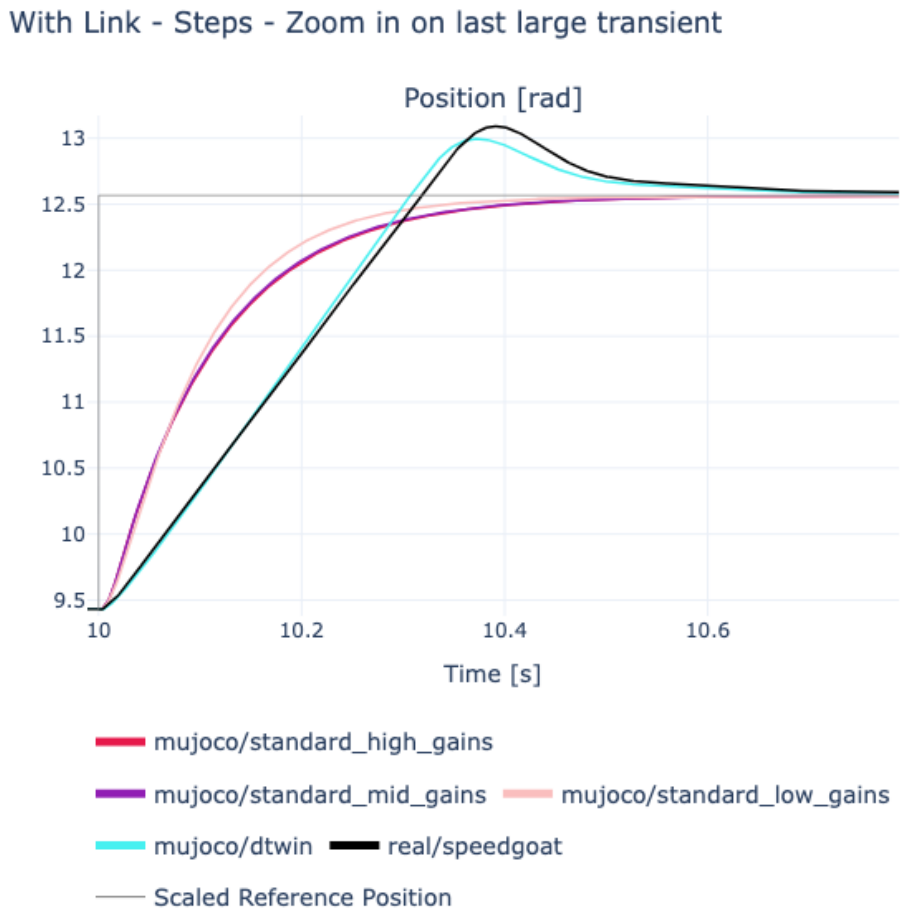
Simulations based on simplified actuator models exhibit varying levels of deviation from real-world behavior, depending on the choice of control gain. Lower gains tend to better match the real system in no-load conditions but fail to accurately track slower ramp trajectories. Conversely, higher gains improve ramp tracking but perform poorly in no-load scenarios. Medium gains offer a better compromise across conditions. However, all configurations, regardless of gain value, consistently show large errors under high-dynamic conditions, particularly during 180° step inputs. In these cases, simplified models fail to capture key dynamic effects such as the significant overshoot observed in the real actuator, as highlighted in
Figure 5.
These results illustrate the dependence of the simplified baseline on the selected gain configuration. A gain set that provides a low prediction error for one trajectory or mechanical condition does not necessarily preserve comparable accuracy when the operating condition changes.
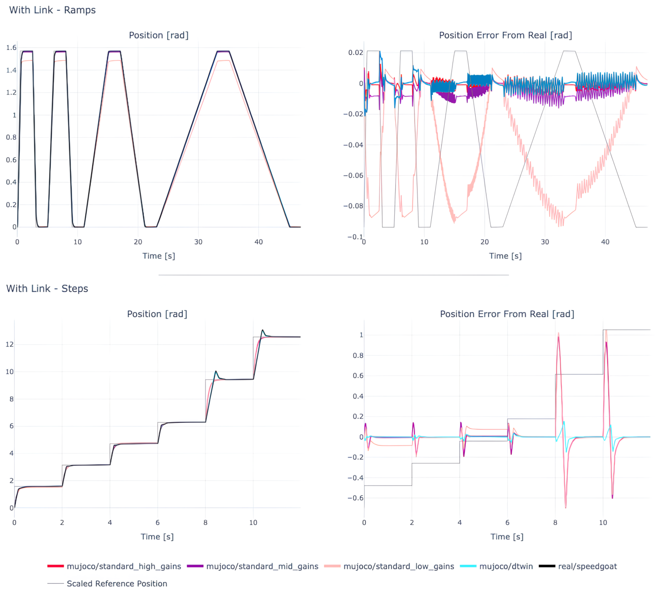
In contrast, simulations using the AUGUR actuator DT consistently achieve lower errors across all tested conditions (as shown in
Figure 6). Specifically, under the slow-dynamic ramp trajectory with load, the position RMSE decreases from
rad in the simplified model (low gains) to
rad with the DT, achieving a
reduction in tracking error. Under the high-dynamic 180° step with load, the error is reduced from
rad to
rad, representing a
reduction.
In terms of predictive performance, the AUGUR DT therefore provides a more consistent estimate of the measured joint-position response across variations in trajectory dynamics, mechanical load, and controller configuration. The improvement is particularly evident for large transients, where the simplified model does not reproduce the measured overshoot. Nevertheless, the DT prediction error also increases under the most aggressive no-load 180° step condition, indicating that some relevant high-dynamic effects remain unmodeled.
Table 2b reports the RMSE of the torque signal relative to real actuator measurements. The most striking result is the behavior of the high-gain standard MuJoCo model, which exhibits dramatically divergent torque profiles, especially under no-load conditions, where the model becomes unstable. In fact, the resulting RMSE approaches the actuator’s peak torque limit, a physically implausible scenario that clearly indicates simulation breakdown.
Excluding this unstable outlier, torque error appears less discriminative between models than position error. For most stable gain configurations, the differences in torque RMSE across platforms are less pronounced.
Consequently, the present experiments provide stronger evidence for improved joint-position prediction than for a general improvement in torque prediction. The torque results nevertheless show that the inclusion of actuator-specific physical limits prevents the extreme unphysical response observed in the high-gain simplified model. Further experimental characterization would be required to establish a broader conclusion regarding torque prediction accuracy.
4.2. Humanoid Arm Simulation (4-DOF)
The 4-DOF experiment evaluates multi-actuator integration and computational scalability rather than predictive accuracy with respect to physical hardware. Because no corresponding physical humanoid arm is available in this study, the quantities reported in
Table 3 describe the tracking behavior of the simulated system relative to its commanded task-space trajectory.
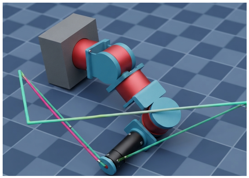
To assess the scalability and applicability of the DT approach, we integrate it into a simulated 4-DOF humanoid arm composed of a 3-DOF shoulder and a 1-DOF elbow (as shown in
Figure 7). The arm is tasked with executing task-space trajectories using the same low-level actuator control architecture evaluated in the 1-DOF pendulum experiments.
This demonstrates that multiple instances of the actuator DT can be integrated within a coupled multi-joint MuJoCo simulation. It should not, however, be interpreted as evidence of sim-to-real predictive accuracy or generalization at the complete arm level.
As previously discussed, we adopt evaluation metrics defined in ISO 9283:1998 to quantify task-space performance. The resulting measurements, capturing positioning and path accuracy, are summarized in
Table 3.
It is important to note that in the test, each arm movement consists of two trajectories: a forward and a return motion. Therefore, measurements were taken for both directions.
The positioning accuracy metric was recorded two seconds after the end of the trajectory, allowing sufficient time for the end-effector to stabilize.
Interestingly, the value in the shortest duration ( s) appears to be better than expected. This is due to the fact that, at the precise moment of measurement, the end-effector was crossing the reference point as a result of oscillations around the target and the aggressive nature of the trajectory required to complete the motion in such a short time. This highlights the importance of collecting multiple measurements to obtain a more reliable and representative evaluation.
4.3. Simulation Timing Benchmark
Despite the increased modeling fidelity, the four DTs complete a 41 s simulation in just 6.503 s, achieving a simulation speedup factor of approximately 6.3× relative to the simulated physical motion duration, on a standard consumer-grade laptop with an Intel i7 CPU.
This result shows that, for the four-actuator configuration considered in this study, the additional electromechanical and embedded-control model complexity does not prevent faster-than-real-time execution. The benchmark therefore supports the computational feasibility of using multiple actuator DT instances in multi-joint robotic simulation, while no claim is made here regarding computational performance for a complete humanoid with substantially more actuators.
5. Discussion
The presented results confirm that actuator DTs narrow the sim-to-real gap compared to simplified actuator models. More specifically, the 1-DOF experiments provide direct evidence of actuator-level predictive accuracy because the simulated joint-position and actuator-torque responses are compared with measurements obtained from the physical PULSE115 actuator under equivalent reference trajectories and mechanical configurations. Across the tested conditions, the AUGUR DT provides more consistent position prediction than the simplified MuJoCo actuator models.
Nevertheless, several limitations remain. First, the physical setup used for pendulum validation was mounted on a lightweight table that introduced noticeable vibrations. This difference in boundary conditions compared to the rigidly fixed simulation may have slightly affected real actuator dynamics. Second, while the DT faithfully reproduced most operating regimes, performance degraded under extreme inputs (e.g., 180° steps without load). This performance degradation in the no-load, high-speed regime is likely due to unmodeled rotor inertia dynamics and magnetic flux saturation. When the external mechanical link is removed, the actuator’s own rotor rotational inertia becomes the dominant load. Under these conditions, high-frequency electromagnetic transients and gearbox backlash, which are simplified in the DT’s mechanical coupling model, become more prominent. These results indicate that the DT is not assumed to reproduce every physical phenomenon affecting the actuator, and prediction errors may remain when unmodeled effects become significant. Third, the scalability of the approach, although promising, has so far been demonstrated only in a 4-DOF arm simulation. Extending to a full humanoid with 30+ actuators will require careful benchmarking of computation time and potentially distributed simulation architectures. Finally, real actuators experience parameter drift due to wear, heating, or controller updates. Incorporating adaptive mechanisms or online parameter identification into the DT framework could help maintain accuracy over time.
Compared to existing simulation approaches relying on simplified actuator models or learned dynamics, the proposed DT offers a physics-based alternative that maintains more consistent position accuracy across the gain and load variations evaluated in this study. In contrast to purely data-driven learned actuator models (e.g., neural networks or LSTMs), which can capture complex hysteretic friction but whose predictive performance depends on the range and quality of the training data, the physics-based DT relies on identified physical parameters (such as winding resistance, inductance, and torque constants). This physical grounding allows the same actuator parameterization to be evaluated when control gains are scaled or load conditions are altered, without trajectory-specific retraining. Furthermore, as shown in the high-gain trials, the DT inherently respects current and torque saturation limits. This prevents the unphysical instabilities and unbounded torques exhibited by simplified models, which lack these boundaries.
For stable configurations, the observation that torque RMSE is less discriminative than position error occurs because both models must exert similar average torques to move the identical rigid-body kinematics along the same trajectory. Consequently, the present experiments provide stronger evidence for improved joint-position prediction than for a general improvement in actuator-torque prediction. However, capturing the low-level electrical and saturation limits remains important for representing physically plausible actuator behavior. This actuator-level fidelity is particularly relevant for humanoid robots, which operate in highly dynamic, contact-rich scenarios. In these platforms, whole-body control, joint impedance, and contact transitions are sensitive to torque saturation boundaries and bandwidth limitations. The potential impact of actuator-level predictive fidelity on walking, manipulation, and other whole-body tasks remains to be evaluated experimentally in future work.
This study provides a quantitative comparison between ideal PD joint models and physics-grounded actuator twins across two simulation platforms (MuJoCo and Simulink). The experimental results identify conditions in which the simplified joint models exhibit substantially larger prediction errors, particularly during large step transients and changes in mechanical load. These results show when explicitly modeling low-level FOC dynamics and actuator limits becomes relevant for reproducing the measured actuator response.
Comparing the C-compiled SPMSM Digital Twin against existing actuator modeling approaches highlights several trade-offs:
Traditional Physics-Based Models: Standard electromechanical equations capture basic motor torque and back-EMF but may omit internal firmware loops (e.g., FOC), current saturation (), and sensor quantization, which are explicitly represented in the AUGUR DT.
System Identification Models: Linear state-space or transfer function models can provide accurate local approximations around identified operating conditions but may require re-identification when control gains or payloads vary substantially from those conditions.
Machine Learning-Based Models: Data-driven models (e.g., neural networks or LSTMs) can fit non-linear friction and hysteresis, but their predictive capability depends on the operating conditions represented in the training dataset.
Hybrid Physics-Data-Driven Models: Hybrid methods combine rigid-body physics with learned residual networks. These methods offer a complementary strategy for modeling effects that are difficult to represent analytically, although a quantitative comparison with such approaches is outside the scope of the present study.
By combining physical parameter identification with low-level firmware execution in compiled C, the proposed Digital Twin maintains physical fidelity across the tested gain and load variations without requiring trajectory-specific training data, executing at on standard CPUs without GPU hardware.
The interpretation of AUGUR as a Digital Twin follows the actuator-level criteria defined in
Section 2.1. In the present study, it is evaluated as an offline executable twin; online synchronization and adaptive operation remain outside the experimental scope.
Its real-time performance and modularity make it potentially suitable for integration in reinforcement learning pipelines, predictive control frameworks, and Hardware-in-the-Loop testing environments. These applications are not evaluated experimentally in the present study and therefore remain subjects for future work.
The 4-DOF humanoid arm experiment addresses computational scalability rather than additional physical validation. Four instances of the same actuator DT can be integrated into a coupled multi-joint MuJoCo simulation and complete a 41 s simulated task in 6.503 s, corresponding to a simulation speedup factor of approximately 6.3 relative to physical motion duration. Because no corresponding physical humanoid arm was available, these results do not establish predictive accuracy, sim-to-real transfer performance, or generalization at the complete arm level.
Future work will therefore focus on physical multi-joint validation, broader excitation profiles, additional mechanical loads, thermal operating conditions, and direct output-torque characterization. Online parameter estimation and bidirectional synchronization may subsequently be incorporated to investigate adaptive Digital Twin operation beyond the offline predictive simulation considered here.
6. Conclusions
The main contributions of this work can be summarized as follows: (i) implementation of an actuator-level DT that captures embedded control, saturation, and sensor dynamics; (ii) experimental validation on a real actuator in a pendulum setup, demonstrating improved fidelity compared to simplified models; and (iii) demonstration of scalability to a 4-DOF humanoid arm simulation running faster than real-time. Predictive performance was evaluated at the actuator level through comparison of simulated and measured joint position and torque responses under equivalent experimental conditions.
We presented a DT framework for actuators that significantly narrows the sim-to-real gap in robotic simulation, particularly under diverse and dynamic operating conditions. By faithfully modeling low-level actuator dynamics, including embedded control loops, saturation limits, and sensor artifacts, the proposed approach delivers substantially higher position prediction accuracy across the tested conditions compared to conventional simplified models.
Our method was empirically validated on a real actuator using a 1-DOF pendulum setup, and it was further demonstrated in a simulated 4-DOF humanoid arm. In the 1-DOF case, predictive accuracy was evaluated directly by comparing simulated joint-position and actuator-torque time histories with measurements from the physical actuator. The DT produced more consistent position predictions across changes in trajectory dynamics, mechanical load, and controller configuration than the simplified baseline.
The evidence for torque prediction is less pronounced. For stable configurations, differences in torque RMSE between the DT and simplified models are smaller than the corresponding position differences. Therefore, the present results support improved position prediction more strongly than a general improvement in torque prediction, and additional experimental characterization is required.
The 4-DOF arm case study demonstrates multi-actuator integration and computational feasibility but does not constitute a physical validation of predictive accuracy at the complete arm level because no corresponding physical arm measurements were available.
These results highlight the potential of actuator DTs to enable scalable, high-fidelity simulations that are both predictive and practical. Within the experimental domain considered in this study, the results support the use of actuator-specific electromechanical and embedded-control models for the forward prediction of physical actuator behavior. Such models are especially valuable for robot design iteration, control policy tuning, and data-efficient training in simulation. Moreover, their modularity and real-time capabilities make them potential candidates for integration into reinforcement learning pipelines, predictive control frameworks, and Hardware-in-the-Loop testing environments.
The present work does not establish failure prediction, predictive maintenance, continuous bidirectional synchronization, online parameter adaptation, predictive accuracy of a complete humanoid robot, or sim-to-real performance of high-level control policies. These capabilities remain outside the scope of the current experimental validation.
Ultimately, this work represents a step toward more generalizable and capable humanoid systems, where realistic simulation is critical to bridging the gap between virtual development and physical deployment. Future research will focus on extending the framework to fullyhumanoid platforms, incorporating adaptive mechanisms for parameter drift, and exploring distributed simulation architectures to support real-time control and learning in high-DOF systems. Physical multi-joint validation and broader load, trajectory, and thermal conditions will be required before extending the predictive claims beyond the actuator-level domain investigated here.
Author Contributions
Conceptualization, M.G., J.M.F., A.O.T., D.S.M. and M.L.E.; methodology, I.J.T.R., M.G., J.M.F., D.S.M., J.T.T.C. and M.L.E.; validation, I.J.T.R. and M.G.; formal analysis, M.G.; investigation, J.M.F., A.O.T., D.S.M. and M.L.E.; resources, I.J.T.R., A.O.T. and M.L.E.; writing—original draft preparation, M.G. and D.S.M.; writing—review and editing, I.J.T.R., M.G., D.S.M., J.T.T.C. and M.L.E.; supervision, D.S.M., J.T.T.C. and M.L.E.; project administration, M.L.E.; funding acquisition, I.J.T.R. and M.L.E. All authors have read and agreed to the published version of the manuscript.
Funding
Grant DIN2024-013443 funded by MICIU/AEI/10.13039/501100011033.
Institutional Review Board Statement
Not applicable.
Informed Consent Statement
Not applicable.
Data Availability Statement
The original contributions presented in this study are included in the article. Further inquiries can be directed to the corresponding author.
Acknowledgments
The authors would like to thank the technical support from ULL, PulsarHRI and ARC.
Conflicts of Interest
Authors Michele Ghilardi, Jordi Marsà Fargas, Añaterve Oval Trujillo, Daniel Sanz Merodio, and Miguel López Estévez were employed by the company Pulsar HRI, Arquimea (Spain). The remaining authors declare that the research was conducted in the absence of any commercial or financial relationships that could be construed as a potential conflict of interest.
Abbreviations
The following abbreviations are used in this manuscript:
| DT | Digital Twin |
| DTs | Digital Twins |
| 1-DOF | One Degree of Freedom |
| 4-DOF | Four Degrees of Freedom |
| HIL | Hardware-in-the-Loop |
| RMSE | Root Mean Square Error |
| URDF | Unified Robot Description Format |
| CAD | Computer-Aided Design |
| PD | Proportional–Derivative |
| EMF | Electromotive Force |
References
- Siciliano, B.; Sciavicco, L.; Villani, L.; Oriolo, G. Robotics: Modelling, Planning and Control; Springer: Berlin/Heidelberg, Germany, 2010. [Google Scholar]
- Mittal, M.; Yu, C.; Yu, Q.; Liu, J.; Rudin, N.; Hoeller, D.; Yuan, J.L.; Singh, R.; Guo, Y.; Mazhar, H.; et al. Orbit: A Unified Simulation Framework for Interactive Robot Learning Environments. IEEE Robot. Autom. Lett. 2023, 8, 3740–3747. [Google Scholar] [CrossRef] [Scilit]
- Agbaraji, E.C.; Inyiama, H.C.; Obiora-Dimson, I. Joint Torque and Motion Computational Analysis for Robotic Manipulator Arm Design. J. Eng. Appl. Sci. 2018, 12, 263–271. [Google Scholar]
- Hou, L.; Zhang, L.; Kim, J. Energy Modeling and Power Measurement for Mobile Robots. Energies 2018, 12, 27. [Google Scholar] [CrossRef] [Scilit]
- Purandhara Sai Santosh, L.; Mishra, N.; Mahanta, S.S.A.; Dharmarajan, V.; Koushik Varma, S.; Shoor, S. Design and analysis of a robotic arm under different loading conditions using FEA simulation. Mater. Today Proc. 2022, 50, 759–765. [Google Scholar] [CrossRef] [Scilit]
- Peng, X.B.; Andrychowicz, M.; Zaremba, W.; Abbeel, P. Sim-to-Real Transfer of Robotic Control with Dynamics Randomization. In Proceedings of the 2018 IEEE International Conference on Robotics and Automation (ICRA), Brisbane, Australia, 21–25 May 2018. [Google Scholar]
- Hwangbo, J.; Lee, J.; Dosovitskiy, A.; Bellicoso, D.; Tsounis, V.; Koltun, V.; Hutter, M. Learning agile and dynamic motor skills for legged robots. Sci. Robot. 2019, 4, eaau5872. [Google Scholar] [CrossRef] [Scilit] [PubMed]
- Black, K.; Brown, N.; Driess, D.; Esmail, A.; Equi, M.; Finn, C.; Fusai, N.; Groom, L.; Hausman, K.; Ichter, B.; et al. π0: A Vision-Language-Action Flow Model. arXiv 2024, arXiv:2410.24164. [Google Scholar]
- Fey, N.; Li, Y.; Wang, H.; Zhang, J.; Chen, L.; Schmidt, T.; Weber, M.; Liu, X.; Hoffmann, R.; Yang, S.; et al. Bridging the Sim-to-Real Gap. arXiv 2025, arXiv:2502.10894. [Google Scholar]
- Lu, Y.; Liu, G.; Xu, X.; Wang, L.; Li, H.; Zhang, Y.; Yang, Z. Digital Twin for Human–Robot Collaboration in Manufacturing: Review and Outlook. Appl. Sci. 2022, 12, 4811. [Google Scholar] [CrossRef] [Scilit]
- Todorov, E.; Erez, T.; Tassa, Y. MuJoCo: A physics engine for model-based control. In Proceedings of the 2012 IEEE/RSJ International Conference on Intelligent Robots and Systems; IEEE: Piscataway, NJ, USA, 2012; pp. 5026–5033. [Google Scholar] [CrossRef] [Scilit]
- Ramuzat, N.; Bonnet, F.; Khelifi, H.; Mestrallet, J.; Arbaoui, A.; Ouezdou, F.B. Actuator Model, Identification and Differential Dynamic Programming for a TALOS Humanoid Robot. In Proceedings of the European Control Conference (ECC), Virtual, 12–15 May 2020. [Google Scholar]
- Mughal, M.A.; Fiorini, P.; Ali, S.; Khan, M.U.; Tahir, M.Z.; Iqbal, J.; Shah, S.I. A Modular Digital Twinning Framework for Safety Assurance of Collaborative Robotics. Front. Robot. AI 2021, 8, 758099. [Google Scholar] [CrossRef] [Scilit] [PubMed]
- Wang, Y.; Liu, H.; Zhang, Y.H.; Li, J.Q.; Zhao, K.L.; Zhou, X.M.; Chen, W.G. Behaviour-Based Digital Twin for Electro-Pneumatic Actuator: Modelling, Simulation, and Validation Through Virtual Commissioning. Electronics 2025, 14, 2434. [Google Scholar] [CrossRef] [Scilit]
- Negri, E.; Fumagalli, L.; Macchi, M. A Digital Twin Demonstrator to Enable Flexible Manufacturing with Robotics: A Process Supervision Case Study. Int. J. Prod. Res. 2021, 59, 4874–4892. [Google Scholar] [CrossRef] [Scilit]
- Díaz, C.P.; García, J.R.; Martínez, L.M.; Gómez, A.S.; Ruiz, F.J.; Torres, M.B.; Soto, R.D.; Vázquez, E.L. Design and Experimental Characterisation of a Novel Quasi-Direct Drive Actuator for Highly Dynamic Robotic Applications. In Proceedings of the IEEE International Conference on Robotics and Automation (ICRA), Yokohama, Japan, 13–17 May 2024. [Google Scholar]
- Ebadpour, M.; Jamshidi, M.B.; Talla, J.; Hashemi-Dezaki, H.; Peroutka, Z. Digital Twin Model of Electric Drives Empowered by EKF. Sensors 2023, 23, 2006. [Google Scholar] [CrossRef] [Scilit] [PubMed]
- Google DeepMind. MuJoCo Documentation: Modeling—Actuators (v3.2.7). 2025. Available online: https://mujoco.readthedocs.io/en/3.2.7/modeling.html#actuators (accessed on 30 July 2026).
- ISO 9283:1998; Manipulating Industrial Robots—Performance Criteria and Related Test Methods. ISO: Geneva, Switzerland, 1998.
Figure 1.
Conceptual representation of the hypothesis evaluated in this work. A simplified actuator model can reproduce the physical response near the operating condition used for identification or tuning, but its fidelity may decrease when trajectory dynamics, mechanical load, or controller configuration changes. An actuator-level Digital Twin that represents the relevant physical and embedded control dynamics is expected to maintain more consistent agreement across these conditions. The asterisks indicate that both axes represent composite metrics rather than single scalar variables: the horizontal axis accounts for variations across multiple operating conditions, while the vertical axis quantifies the model’s overall deviation from physical bench test data.
Figure 1.
Conceptual representation of the hypothesis evaluated in this work. A simplified actuator model can reproduce the physical response near the operating condition used for identification or tuning, but its fidelity may decrease when trajectory dynamics, mechanical load, or controller configuration changes. An actuator-level Digital Twin that represents the relevant physical and embedded control dynamics is expected to maintain more consistent agreement across these conditions. The asterisks indicate that both axes represent composite metrics rather than single scalar variables: the horizontal axis accounts for variations across multiple operating conditions, while the vertical axis quantifies the model’s overall deviation from physical bench test data.
Figure 2.
Experimental platform used for actuator-level predictive validation. (Left): Physical single-degree-of-freedom pendulum driven by the PULSE115 actuator. (Right): Corresponding MuJoCo representation with equivalent load geometry and inertial properties. Identical reference trajectories are applied to the physical and simulated systems to compare predicted and measured actuator responses.
Figure 2.
Experimental platform used for actuator-level predictive validation. (Left): Physical single-degree-of-freedom pendulum driven by the PULSE115 actuator. (Right): Corresponding MuJoCo representation with equivalent load geometry and inertial properties. Identical reference trajectories are applied to the physical and simulated systems to compare predicted and measured actuator responses.
Figure 3.
Schematic block diagram of the cascaded position control system. The controller utilizes an outer proportional (P) position loop, an intermediate proportional–integral (PI) velocity loop, and an inner PI current loop operating FOC to regulate motor currents under physical limits.
Figure 3.
Schematic block diagram of the cascaded position control system. The controller utilizes an outer proportional (P) position loop, an intermediate proportional–integral (PI) velocity loop, and an inner PI current loop operating FOC to regulate motor currents under physical limits.
Figure 4.
General architecture of a robotic system integrated with actuator Digital Twins.
Figure 4.
General architecture of a robotic system integrated with actuator Digital Twins.
Figure 5.
Zoom-in on the final large transient of the multi-step experiment with the link attached, highlighting the significant overshoot exhibited by the real system, which is not reproduced by the simplified actuator models and is more closely captured by the AUGUR DT.
Figure 5.
Zoom-in on the final large transient of the multi-step experiment with the link attached, highlighting the significant overshoot exhibited by the real system, which is not reproduced by the simplified actuator models and is more closely captured by the AUGUR DT.
Figure 6.
Signals for the configuration where the link is fastened to the actuator output. (Top row): (left): measured and predicted position trajectories from all simulation platforms during the multi-ramp experiment; (right): corresponding position prediction errors relative to the physical actuator. (Bottom row): Same layout for the multi-step experiment, which excites faster actuator dynamics. Blue shades: Indicate closer proximity and minimal tracking error.
Figure 6.
Signals for the configuration where the link is fastened to the actuator output. (Top row): (left): measured and predicted position trajectories from all simulation platforms during the multi-ramp experiment; (right): corresponding position prediction errors relative to the physical actuator. (Bottom row): Same layout for the multi-step experiment, which excites faster actuator dynamics. Blue shades: Indicate closer proximity and minimal tracking error.
Figure 7.
Simulated 4-DOF humanoid robot arm executing a task-space trajectory in MuJoCo. Colored lines illustrate the geometric deviation between the simulated end-effector path and the commanded reference trajectory.
Figure 7.
Simulated 4-DOF humanoid robot arm executing a task-space trajectory in MuJoCo. Colored lines illustrate the geometric deviation between the simulated end-effector path and the commanded reference trajectory.
Table 1.
Physical specifications and parameters of the PULSE115 quasi-direct-drive actuator identified following [
16].
Table 1.
Physical specifications and parameters of the PULSE115 quasi-direct-drive actuator identified following [
16].
| Characteristic/Parameter | PULSE115 Value |
|---|
| Stator winding resistance () | |
| Permanent magnet flux linkage () | |
| Number of pole pairs (P) | 21 |
| Rotor and coupling inertia (J) | |
| Nominal speed | |
| Viscous friction coefficient (B) | |
| Static Coulomb friction () | |
| Rated torque | @ 48VDC |
| Peak torque | @ 48VDC |
| Backdrive torque | |
| Transmission type | Planetary |
| Gear ratio (N) | 5:1 |
| Backlash | |
| Max. speed @ rated torque | @ 48VDC |
| Max. speed @ peak torque | @ 48VDC |
| Actuator mass | |
| Outer diameter | |
| Width | |
| Hollow shaft diameter | |
| Rated current | |
| Peak current () | |
| DC Bus voltage | |
| Encoder resolution | (Input/Output) |
Table 2.
Root Mean Square Error (RMSE) between predicted actuator signals and measurements from the physical actuator for position and torque across platforms and experimental conditions. Lower values indicate smaller prediction error. The red color gradient highlights prediction error: darker red indicates higher RMSE values.
Table 2.
Root Mean Square Error (RMSE) between predicted actuator signals and measurements from the physical actuator for position and torque across platforms and experimental conditions. Lower values indicate smaller prediction error. The red color gradient highlights prediction error: darker red indicates higher RMSE values.
| (a) Position Prediction Error RMSE [rad] |
| System | With Link | No Link |
| ramps | 90° steps | 180° steps | ramps | 90° steps | 180° steps |
| MuJoCo Standard Low Gains |
0.0567
|
0.0618
|
0.3210
|
0.0137
|
0.0415
|
0.3904
|
| MuJoCo Standard Mid Gains |
0.0065
|
0.0386
|
0.3068
|
0.0059
|
0.0413
|
0.3883
|
| MuJoCo Standard High Gains |
0.0030
|
0.0387
|
0.3042
|
0.0335
|
0.0521
|
0.3881
|
| MuJoCo + AUGUR dtwin |
0.0042
|
0.0091
|
0.0406
|
0.0055
|
0.0234
|
0.1733
|
| Simulink + AUGUR dtwin |
0.0043
|
0.0109
|
0.0237
|
0.0057
|
0.0117
|
0.1080
|
| (b) Torque Prediction Error RMSE [Nm] |
| System | With Link | No Link |
| ramps | 90° steps | 180° steps | ramps | 90° steps | 180° steps |
| Mj/Std Low |
0.333
|
2.344
|
4.045
|
0.371
|
1.546
|
2.474
|
| Mj/Std Mid |
0.475
|
3.790
|
4.828
|
0.397
|
1.997
|
2.792
|
| Mj/Std High |
1.587
|
3.984
|
4.962
|
63.081
|
63.091
|
63.215
|
| Mj/Dtwin |
0.417
|
1.926
|
3.150
|
0.335
|
1.611
|
2.532
|
| SL/Dtwin |
0.419
|
2.302
|
2.870
|
0.339
|
1.351
|
2.347
|
Table 3.
Task-space path accuracy and positioning accuracy for the simulated 4-DOF arm. These values quantify deviation between the simulated end-effector trajectory and the commanded reference and are not sim-to-real prediction errors.
Table 3.
Task-space path accuracy and positioning accuracy for the simulated 4-DOF arm. These values quantify deviation between the simulated end-effector trajectory and the commanded reference and are not sim-to-real prediction errors.
| System: | 0.5 s | 1 s | 4 s | 10 s |
|---|
| MuJoCo + AUGUR | Forward | Return | Forward | Return | Forward | Return | Forward | Return |
|---|
| 0.3559 | 0.3622 | 0.3372 | 0.3408 | 0.3009 | 0.3023 | 0.2917 | 0.2923 |
| 0.00003 | - | 0.00018 | - | 0.00016 | - | 0.00018 | - |
| Disclaimer/Publisher’s Note: The statements, opinions and data contained in all publications are solely those of the individual author(s) and contributor(s) and not of MDPI and/or the editor(s). MDPI and/or the editor(s) disclaim responsibility for any injury to people or property resulting from any ideas, methods, instructions or products referred to in the content. |




 ,
,