Article

A Novel Soft Gripper Featuring a Self-Bending Contraction Actuator (SBCA) with Reconfigurable Bending Characteristics

Mechanical Engineering, University of Birmingham, Birmingham B15 2TT, UK
*
Author to whom correspondence should be addressed.
These authors contributed equally to this work.
Actuators 2026, 15(8), 434; https://doi.org/10.3390/act15080434
Submission received: 31 March 2026 / Revised: 11 June 2026 / Accepted: 23 June 2026 / Published: 11 August 2026
(This article belongs to the Special Issue Actuation and Sensing of Intelligent Soft Robots—2nd Edition)

Abstract

Soft pneumatic actuators are widely used in robotic manipulation due to their compliance and adaptability; however, their performance is typically fixed at the fabrication stage, limiting their suitability for applications requiring task-specific tuning. This paper presents a reconfigurable self-bending contraction actuator (SBCA) that enables post-fabrication adjustment of mechanical behaviour through interchangeable internal reinforcing elements. The proposed design introduces novel end fittings that allow rapid, non-destructive insertion and replacement of reinforcing rods, transforming the actuator from a fixed-function component into a tunable system. Four reinforcing rod geometries are designed and experimentally evaluated to investigate the influence of stiffness distribution on actuator performance. Results show that reinforcement geometry significantly affects both bending curvature and force transmission, with the proposed configurations achieving up to 77° bending at 2 bar and a maximum fingertip force of 4.73 N. A 25.42% increase in bending angle and a 10% increase in force are observed relative to a baseline configuration. Beyond performance improvements, the study establishes a direct relationship between internal structural variation and actuator output, highlighting a controllable trade-off between bending curvature and force generation. This provides a practical framework for tuning actuator behaviour without redesign or reconstruction. A three-finger soft gripper integrating the proposed SBCA is developed and validated through grasping experiments on objects with varying geometries and mechanical properties, demonstrating robust and adaptive manipulation. The proposed approach advances SBCA design from fixed-performance actuators toward reconfigurable and application-adaptable soft robotic systems.

1. Introduction

Over the past few decades, robotic manipulation has undergone a significant shift from rigid-body systems toward compliant, soft-material-based designs. This transition has been driven by the growing demand for robotic systems capable of safely interacting with fragile, deformable, or uncertain objects in applications ranging from industrial handling to medical and service robotics [1,2,3]. Soft grippers, in particular, offer key advantages such as inherent compliance, low inertia, adaptability to object shape, and reduced control complexity, making them strong candidates for next-generation manipulation systems [4,5]. Soft robotic actuators have attracted increasing attention owing to their inherent compliance, safety during human interaction, and ability to undergo large deformations [6,7,8].
Among the various soft actuation technologies, pneumatic artificial muscles (PAMs) have emerged as one of the most widely adopted solutions due to their high power-to-weight ratio, simplicity of construction, and cost-effectiveness [9,10]. A typical PAM consists of an elastomeric inner bladder encased within a braided sleeve, where pressurisation results in radial expansion and axial contraction, mimicking the behaviour of biological muscles [11,12]. By modifying the braid angle and structural constraints, PAMs can be configured to produce either contraction or extension, with a critical transition occurring at a braid angle of approximately 54.7° [12].
To extend the functionality of PAMs, researchers have introduced asymmetric constraints to induce bending motion. One such design is the self-bending contraction actuator (SBCA), in which a flexible but inextensible reinforcing element is embedded along one side of a contraction-type PAM, generating curvature during actuation [13,14]. SBCAs have been successfully applied in soft robotic fingers, continuum manipulators, and adaptive grippers, demonstrating their potential for compliant grasping and manipulation tasks.
Recent studies have explored modular reinforcement strategies to improve actuator adaptability and facilitate rapid reconfiguration without redesigning the actuator body [15]. The fibre reinforcement constrains radial expansion while enabling programmable deformation, a strategy widely adopted in fibre-reinforced soft pneumatic actuators [16,17].
Previous studies have identified the reinforcing element as a dominant factor influencing SBCA performance, particularly in terms of bending stiffness, curvature, and payload capacity. However, systematic experimental investigations into how variations in reinforcement geometry affect actuator behaviour remain limited. Furthermore, existing actuator designs do not provide a practical mechanism for rapidly implementing such variations within a single platform. Recent modular soft actuator architectures have demonstrated the potential for reconfigurable pneumatic systems with application-specific performance tuning [18], highlighting growing interest in adaptable soft robotic hardware.
To address these challenges as mentioned in Table 1, this paper proposes a reconfigurable SBCA architecture that enables non-destructive modification of the internal reinforcing element. The design introduces a set of novel end fittings that allow reinforcing rods to be easily inserted, removed, and replaced without altering the actuator body or damaging surrounding components. This transforms the SBCA from a fixed-performance device into a tunable actuation system, where mechanical behaviour can be adjusted post-fabrication. In addition to the design innovation, this work presents a systematic experimental study on the influence of reinforcing rod geometry on actuator performance. Four distinct rod configurations are developed and evaluated to investigate their effect on bending angle and fingertip force. Through this analysis, the study establishes a direct relationship between stiffness distribution and actuator output characteristics, providing insight into how internal structural variation governs SBCA behaviour.
The main contributions of this work are therefore twofold. First, a novel reconfigurable SBCA design is introduced, enabling rapid and non-destructive modification of the reinforcing element. Second, a comparative experimental framework is presented that demonstrates how reinforcement geometry can be used as a controllable design parameter to tune actuator performance. A three-finger soft gripper incorporating the proposed actuator is also developed and validated, demonstrating the practical applicability of the approach for adaptive grasping tasks. By enabling post-fabrication tunability and establishing a link between internal structure and actuator performance, this work advances SBCAs from fixed-function components toward adaptable soft robotic systems.

2. SBCA Finger and Gripper

2.1. Design of the SBCA Finger and Gripper

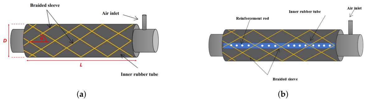
The basic structure of the SBCA, Figure 1b, consisted of an air-tight bladder surrounded by a braided mesh, sealed at both ends with a small air inlet. A flexible incompressible rod is used to prevent contraction on one side of the actuator to induce bending. These rods are usually sewn into place between the braid and bladder layers [13,14], permanently fixing them to the SBCA and requiring highly destructive processes to replace them in the event of failure or for the purposes of altering the SBCA’s performance.
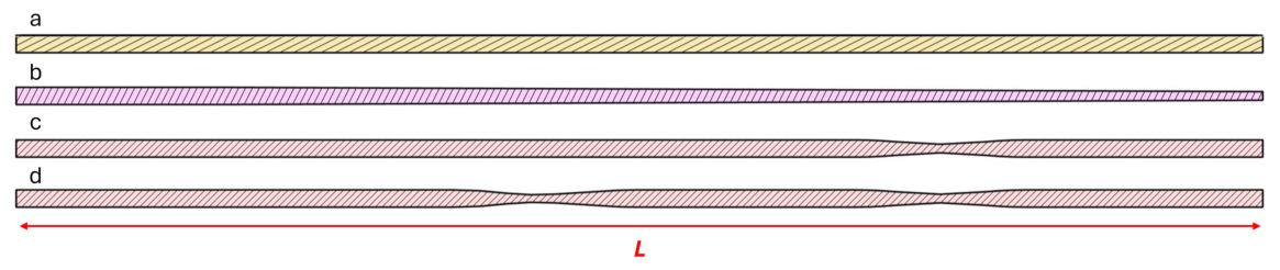
To investigate the effect of rod design variations on the performance of the SBCA, it was necessary to develop a set of novel end fittings that facilitated the non-destructive replacement of the reinforcing rod and allowed for quick assembly/disassembly of the SBCA. A side profile of the four reinforcing rods investigated can be seen in Figure 2. Due to the design of the end fittings, the maximum allowable cross-section for the rods is a width (W) of 3 mm and height (H) of 2 mm. The cross-section of the control rod, Figure 2a, is set to this maximum and is constant along its length. Figure 2b shows a tapered rod with W 3 mm and H 2 mm for a length of 25 mm; H then decreases linearly from 2 mm to 1 mm. Figure 2c depicts a rod with a thinned section; the purpose of this is to create a discrete bending location and reduce bending resistance without using mechanical pivots, which would increase the cross-section of the rod and therefore the bulkiness of the SBCA. The rod shown in Figure 2d features two identical thinned sections. Max and min H for the 1 and 2 joint rods are 2 mm and 1mm, respectively, and the thinned sections have concave and convex radii of 56.5 mm and 50 mm, respectively. W is constant along the length (L) of all rods, where L is 145 mm.
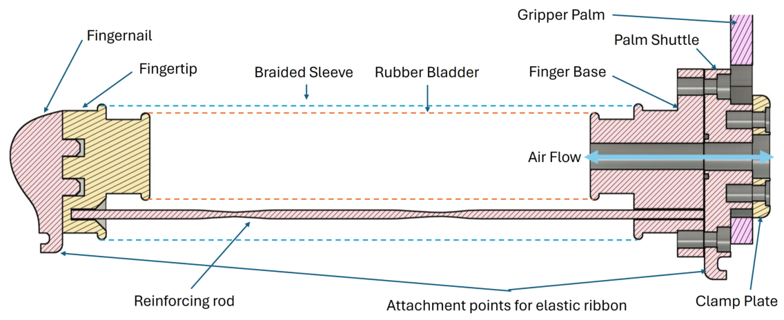
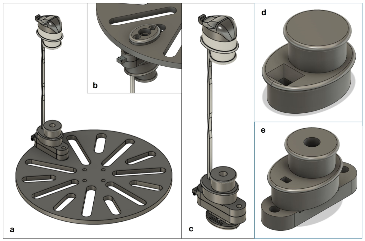
The skeletal structure of the proposed finger can be seen in Figure 2c, and a cross-section of the assembled actuator is pictured in Figure 3. The finger is constructed from seven major components: the finger base and tip (novel end fittings), palm shuttle, fingernail, reinforcing rod, and the braid and bladder (depicted as dotted lines). The reinforcing rod is inserted through a hole in the finger base, slides between the braid and bladder and inserts into a corresponding hole in the fingertip. The palm shuttle is then screwed to the finger base, preventing push-out of the rod. An O-ring was placed between the two mating faces to create an air-tight seal. The palm shuttle is located in slots of the gripper palm, as pictured in Figure 4a, and bolts to the clamp plate, allowing the position of the finger on the palm to be reconfigured. The fingernail is then plugged into the fingertip by friction fit; this modular design allows for future experimentation with fingernail designs and materials for different kinds of grasp. The overall length of the finger is 165 mm with an actuator length of 120 mm.
The bladder and braid are independently fixed to the circular and elliptical structures of the end fittings, respectively. This is not typical for SBCA construction and allows space in the design for holes that fix and guide the reinforcing rod. The combination of these design features makes the proposed end fittings novel to the extent of the author’s knowledge.
During the design process, a chamber was added to the fingertip hole to aid in the insertion of the rod, significantly reducing the reconfiguration time from 223 s to 97 s (not including fixation to the palm). The time required to detach and reattach a finger to the palm is 16 s and 52 s, respectively.
Initial CAD design revealed that the conventional cylindrical structure of the SBCA end fittings would result in packaging issues when attached to the palm. An elliptical structure was therefore developed to reduce the profile of the finger, resulting in a less bulky, more efficient design. A raised ring portion was also added to the end fittings, inspired by work presented in [23], to prevent slip off of the braid and bladder, and attachment points for an elastomeric ribbon were added to the finger base and fingernail to aid in the retraction of the finger to its original position.

2.2. Analysis of the SBCA Finger and Gripper

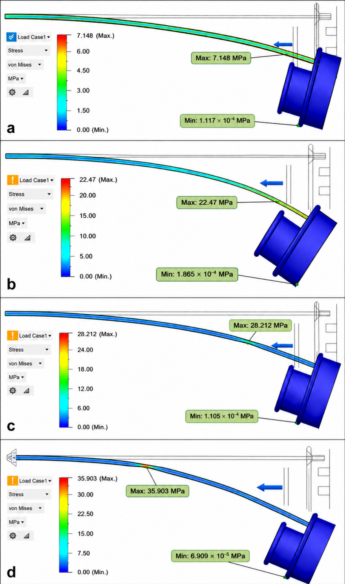
An FEA analysis of the proposed reinforcing rods was conducted; a comparison of results for each rod is presented in Figure 5. The simulations were modelled by constraining the base of the rod and applying a load (depicted as a blue arrow) of 1 N (roughly 100 g) to the fingertip along the axis of contraction of the SBCA. A 100 g load was chosen based on the masses of graspable objects (1–1400 g) and the tip forces (0–13.5 N) of other comparable pneumatically actuated grippers [14,24,25]. The chosen load is towards the lower end of the established range, as the model only considers the bending resistance of the PLA rod. During actuation of the SBCA, the rod is squeezed between the bladder and braid until the radial forces of the bladder are balanced by the constraints of the braided sleeve. These forces help to spread the load on the rod through increased contact area and support the structure during actuation [23]. Consequently, the predicted deflections are likely to be higher than the measured values, and bending curvature may appear to be more uniform than that pictured in Figure 5. The analysis does, however, provide a good qualitative comparison of the reinforcing rods, with the control rod showing the lowest deflection and highest safety factor (this is expected). The maximum deflection is experienced jointly by the tapered and 2 joint rods. However, the 2 joint rod demonstrates a significantly lower safety factor. The analysis also serves to identify stress concentrations and, therefore, potential failure modes of the rods. Table 2 lists the minimum safety factor and maximum deflection for each rod at a force of 1 N each.

2.3. Fabrication of the SBCA Finger and Gripper

As previously mentioned, one of the driving factors for soft actuator development is the need to decrease the cost of production. Low-cost, widely available materials and manufacturing techniques are therefore prioritised. Materials and manufacturing for the major components are listed in Table 2.
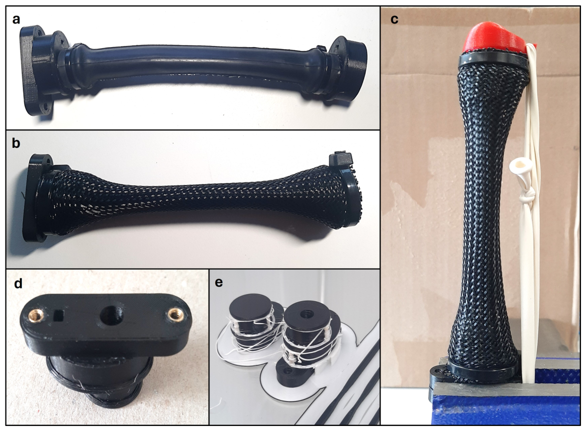
First, brass heat-set inserts are set into the relevant holes of the 3D-printed components, as shown in Figure 6d. Due to the modular design of the finger, threaded components are likely to experience high wear and tear. Threaded inserts are used for all threads to mitigate these effects and extend the service life of the components. M3 inserts are used for all threads except the air inlet, which features an M5 insert to accommodate an M4 tube push-in pneumatic connection; all other components are fastened using M3 socket head screws. A soldering iron is used to heat and press the inserts into position. This technique presented no problems for small-scale production. However, those considering mass production of the end fittings should refer to the installation press presented in [26].
Second, the bladder is stretched over the circular sections of the end fittings and secured with a vulcanising rubber solution and zip ties to ensure an air-tight seal (Figure 6a); contact surfaces are roughened with sandpaper to improve the quality of the bond. While the vulcanising rubber solution was used purely to achieve an air-tight seal, it was found during construction of the actuator that it acted as a lubricant, aiding greatly in the insertion and alignment of the end fittings.
The braided sleeve is then slipped over the bladder and end fittings and fastened to the elliptical sections with zip ties (Figure 6b). The ends of the braid are melted with a lighter, which prevents fraying and helps to further secure the zip tie in place. The unpressurised diameters of the braid and bladder are 20 mm and 18 mm, respectively; the bladder thickness is 1mm. All major components, excluding the braid and bladder, were 3D-printed using an Ultimaker S5 Pro from Ultimaker, UK. When printing the finger base and tip, the printer experienced issues with the deposition of the breakaway support material seen in Figure 6e. These components must be sufficiently spaced apart on the build plate during printing to prevent rogue support material from affecting the quality of the adjacent prints. The fingernail is printed from TPU with 15% infill to create a soft and deformable structure. This has the effect of increasing the contact surface between the fingertip and the grasped object and improves the reliability of the grasp [27]. The clamp plate features two strips of elastomeric material to increase friction with the palm and ensure a solid fixture. The elastomeric ribbon is fabricated from a long modelling balloon and has a relaxed length of 115mm. It is stretched between the attachment points on the fingernail and palm shuttle and is held in place by its own tension forces, as pictured in Figure 6c. The mass of the proposed SBCA and the developed 3-finger gripper is 36 g and 182 g, respectively.

3. Experiments

3.1. Characterisation of the SBCA Finger

To understand the performance capabilities of the SBCA finger, characteristics such as the operating pressure, reachable work volume, and fingertip force at different pressures are studied. The investigation into operating pressure was primarily conducted to identify the maximum pressure before failure and therefore establish the range of pressures at which the subsequent tests could be conducted safely. The studies on the bending and force characteristics were conducted for all four proposed reinforcing rods to establish the effect of their respective designs on the maximum bending angle and fingertip force of the SBCA.
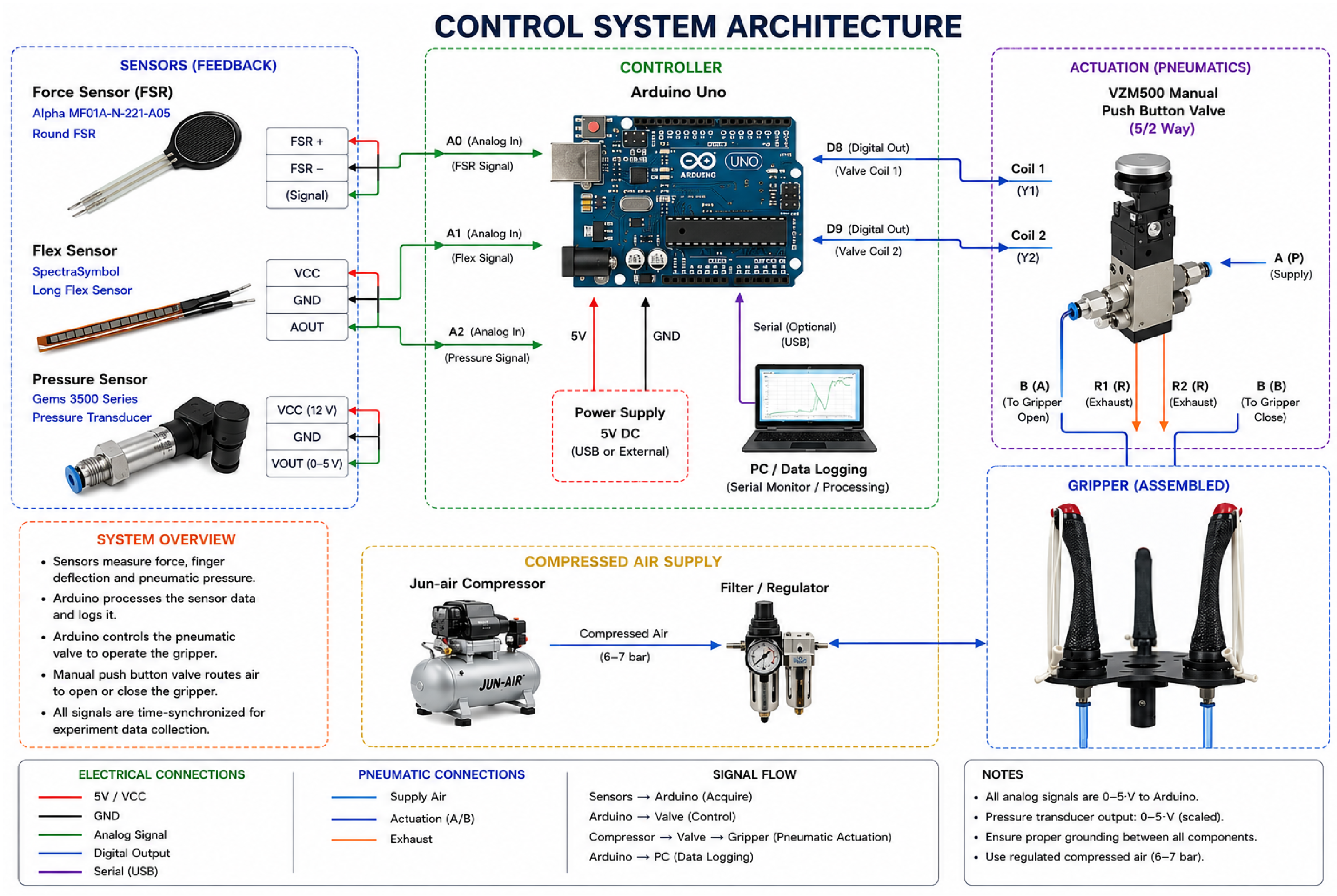
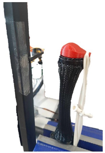
When considering potential applications of a soft gripper, the force a single finger can apply to an object is an essential parameter. This section presents a study into the force developed at the fingertip of the proposed SBCA when pressurised to a maximum of 2 bar. Experiments were performed to study the bending angle at different pressures for the four proposed reinforcing rods as shown in the schematic diagram of the control system architecture Figure 7. A blocked force test was carried out by fixing an Alpha MF01A-N-221-A05, from Alpha (Taiwan), round force-sensitive resistor to a frame. The SBCA was clamped in a bench vice and the frame was positioned in front such that the fingertip contacted the sensor when the SBCA was pressurised to 0.8 bar; an image of the blocked force test rig can be found in Figure 8.
Pressure was gradually increased to 2 bar over a period using a manual pressure regulator, then decreased back to 0 bar to identify potential hysteresis effects. Due to the design of the regulator, however, a smooth pressure decrease was challenging to achieve and, for most repeats, was more akin a total pressure vent.
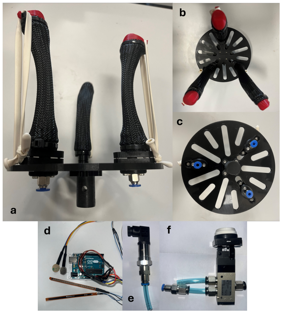
The SBCA was clamped vertically in a vice, and air was supplied to the SBCA from a Jun-Air Oil-Lubricated Piston Air Compressor from Cole-Parmer UK, fitted with a manual pressure regulator. The bending angle was measured using a SpectraSymbol long flex sensor, from SpectraSymbol, US, attached to the back of the finger and an Arduino Uno, from Arduino S.r.l., Italy. The sensor gives an analogue reading in ohms; the resistance increases as it flexes, so the change in angle is read by taking the difference of the two resistance values and convert it into degrees within the microcontroller as shown in Figure 9.

Operating Pressure

The developed gripper systems must strive to offer high efficiency by eliminating energy losses, thus decreasing the operating cost of the gripper. For pneumatic systems, air leakage is usually responsible for most energy losses [28]. This is especially the case for the prototype stage of design due to imperfections caused by hand finishing of components and manual construction. To identify leaks in the proposed design, the SBCA was pressurised to 0.5 bar and submerged in water. A moderate volume of bubbles was observed from the mating faces between the palm shuttle and finger base. The O-ring was therefore replaced with another of larger thickness for all actuators, and the test was repeated until no bubbles were observed. To establish the maximum operating pressure, one of five assembled SBCAs was chosen for destructive testing. The SBCA was fixed to a table behind a protective screen and the pressure was increased in 0.5 bar increments until catastrophic failure occurred at 3 bar. It was observed that failure occurred because of the braided sleeve slipping under the zip tie, securing it to the fingertip and sliding down over the bladder. Without the braid to constrain radial expansion, the top section of the bladder over inflated and ruptured. It was also observed that actuation only began at around 0.25 bar. This is referred to as a pressure dead band. Due to the design of the SBCA, there is a small gap between the braid and bladder layers. The bladder must first expand and close this gap to contact the braid before any contraction can occur. From this test, a maximum operating pressure of 2 bar was chosen, giving a safety factor of 1.5. The remaining four actuators were then tested under the same conditions, to a pressure of 2 bar, to check the quality of the construction and ensure that subsequent tests were equally safe and practical. All pressure tests were conducted with no reinforcing rod to decrease potential shrapnel in the event of failure. Images of the failed actuator can be found in Appendix A.

3.2. Kinematics of the SBCA

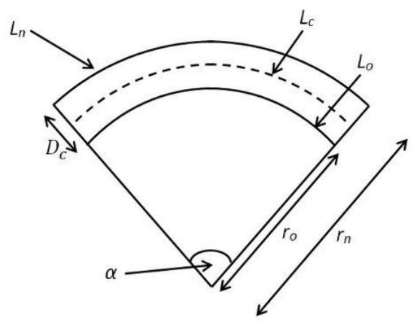
Various models have been proposed for modelling of the actuation force of the PMA [5]. These models are generally computationally intensive and require inputs such as elastic modulus or friction coefficients. Fewer models for the SBCA have been proposed; a geometric model for the bending angle of an extensor PMA has been selected from work presented in [29] and adapted to fit the parameters of an SBCA. A diagram of the bending muscle geometry can be found in Appendix A. First, L n is set by the length of the reinforcing rod, which is 0.12m for the free actuation length as some of the rod is supported within the end fittings. L 0 is the length of the contracted side of the SBCA and is calculated using Equation (2).
Rod Length , L n = r n α
L 0 = b cos ( θ ) = r 0 α
where b is the length of a single braid fibre (0.123 m), determined experimentally by deconstructing part of the actuator, and θ is the braid angle, depicted in Figure 1a, during pressurisation (43°). This was measured by applying two lengths of electrical tape to the actuator, one parallel to the braid and the other perpendicular to the axis of contraction, and then removing and measuring the angle at the intercept. After rearranging Equations (1) and (2) to make r 0 and r n the subjects, D c is given by Equation (3).
D c = r n r 0
Without prior knowledge of α , however, D c cannot be calculated and was therefore measured at 0.02 m. Substituting Equations (1) and (2) into Equation (3) and rearranging to make α the subject gives Equation (4).
α = L n b cos ( θ ) D c = 1.50 rad = 85 . 9
The model assumes that the curvature of the finger is a perfect arc and is therefore most comparable to the bending of the control rod due to its uniform thickness, creating a bending profile with the most similarities. From Table 3, the measured bending angle of the control rod is 31.32% lower than predicted. This is not surprising as the model does not account for the hyperelastic nature of the bladder, the elastic potential in the rod, or the friction forces between the braid and bladder or braid fibres, all of which resist the bending force. Another reason for the inaccuracy of the model is that the method used for measuring theta during contraction was challenging and may not have yielded accurate values.

3.3. Three-Finger Soft Gripper

Using the proposed SBCA, a three-finger soft gripper was developed. The gripper palm features multiple slots to allow for the reconfiguration of the three fingers or additional SBCAs for the handling of larger payloads. Air pressure is supplied evenly to all three fingers through a series of t-splitter push-in pneumatic connections and a M4 pipe.
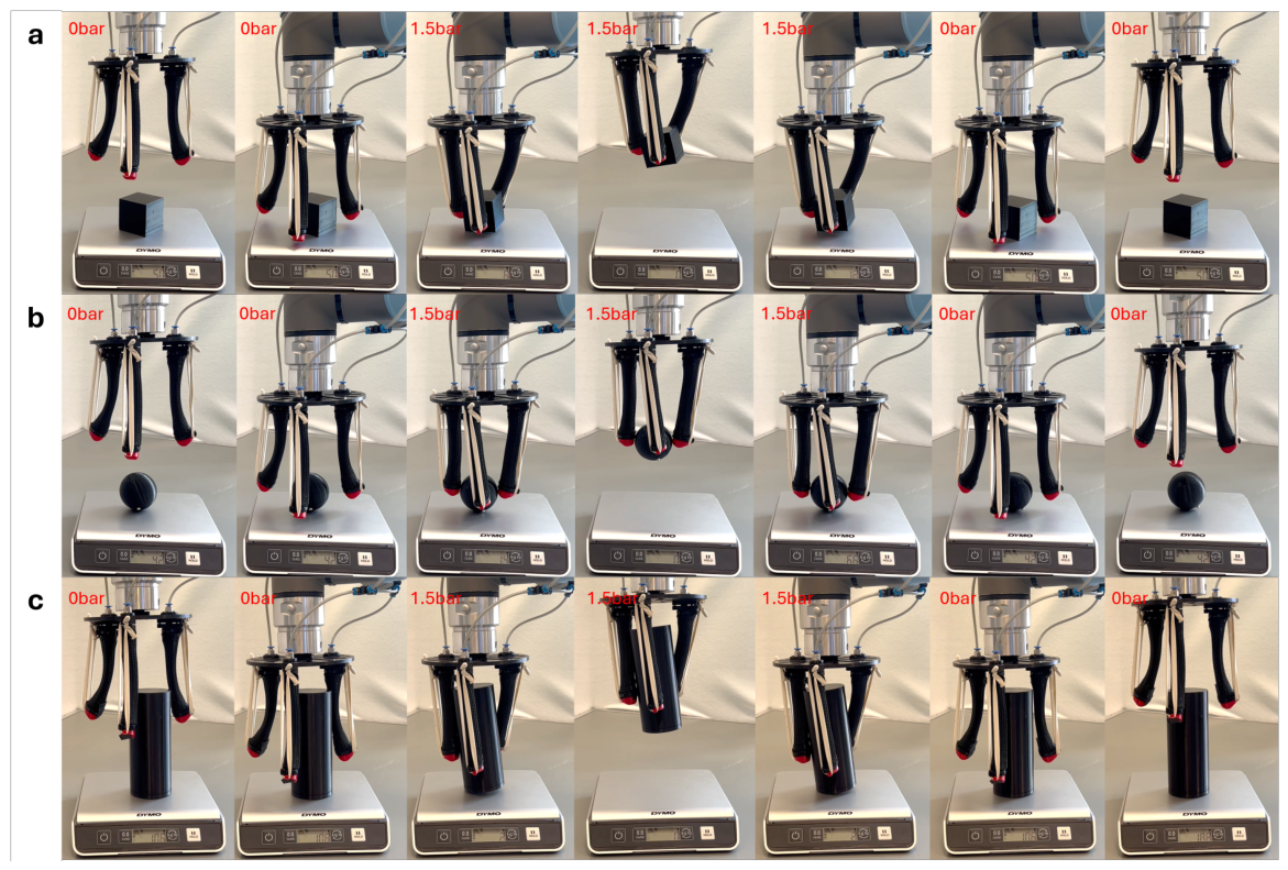
To investigate the grasping capabilities of the gripper, three common shapes, i.e., cube, sphere, and cylinder, were 3D-printed and tested, with 50 g, 42 g, 106 g as their respective masses as shown in Figure 10. The criteria for the selection of these objects were partly based on the range of object shapes and sizes grasped by the RBO Hand 2 [24]. However, soft grippers are generally praised for their compliance and ability to handle deformable and irregularly shaped objects. It is therefore necessary to include objects of varying mechanical properties in the grasp test. For each test, the gripper was secured to a length of wood held in a bench vice and pressurised to 1.5 bar. The items were handed to the gripper to simulate a successful object detection and localisation. The proposed gripper offers advantages over the grippers presented in [13,14,24]; its modular design allows for the positions and number of fingers on the palm to be configured rapidly to suit the requirements of the application. The fingertip force and bending angle can also be reconfigured for each finger independently; this could decrease the need for complex pressure control, as a variety of bending behaviours can be achieved at constant actuation pressures.

4. Results

This section presents a systematic evaluation of the proposed self-bending contraction actuator (SBCA), with particular emphasis on how variations in reinforcing rod geometry influence actuator performance. The results are structured to highlight the relationship between internal stiffness distribution and key output characteristics, namely bending curvature and fingertip force.

4.1. Bending Characteristics

Experiments were performed to evaluate the bending angle of the SBCA under varying actuation pressures (1–2 bar) for each reinforcing rod configuration. The actuator was clamped vertically, and pressure was supplied via a regulated compressor. Bending angle was measured using a flex sensor interfaced with an Arduino, with repeated trials conducted to ensure consistency.
The results demonstrate that reinforcing rod geometry plays a dominant role in governing actuator curvature, confirming that stiffness distribution along the actuator length is a primary determinant of bending response. The control rod, characterised by a uniform cross-section, exhibited the lowest bending angle (59° at 2 bar), reflecting its relatively high and uniform bending stiffness.
In contrast, rods incorporating geometric variation—such as the tapered, 1-joint, and 2-joint designs—produced significantly higher curvature. The tapered rod achieved the largest bending angle of 77°, indicating that gradual reduction in cross-sectional stiffness promotes increased deformation under identical pressure inputs. The 1-joint and 2-joint rods introduced localised regions of reduced stiffness, resulting in non-uniform curvature profiles and enabling more concentrated bending at predefined locations.
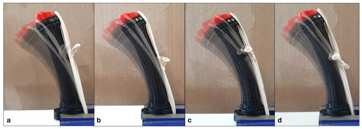
The reachable work envelope of the actuator, as shown in Figure 11, further illustrates how rod geometry influences deformation shape. At lower pressures (1 bar), the control rod exhibited minimal deflection and near-linear behaviour, whereas the other configurations displayed increasing curvature. As pressure increased, all rods demonstrated greater deformation; however, the curvature profiles differed significantly depending on stiffness distribution.
Across all configurations, a nonlinear relationship between pressure and bending angle was observed. This behaviour can be attributed to the combined effects of hyperelastic deformation of the bladder, interaction forces between the braid and bladder, and progressive engagement of the reinforcing rod. Minor inconsistencies observed between trials are likely due to manual pressure regulation and measurement limitations. Nevertheless, the overall trends remain consistent.
These results establish that reinforcement geometry provides an effective mechanism for tuning actuator curvature without modifying the actuator body, supporting the concept of post-fabrication configurability.
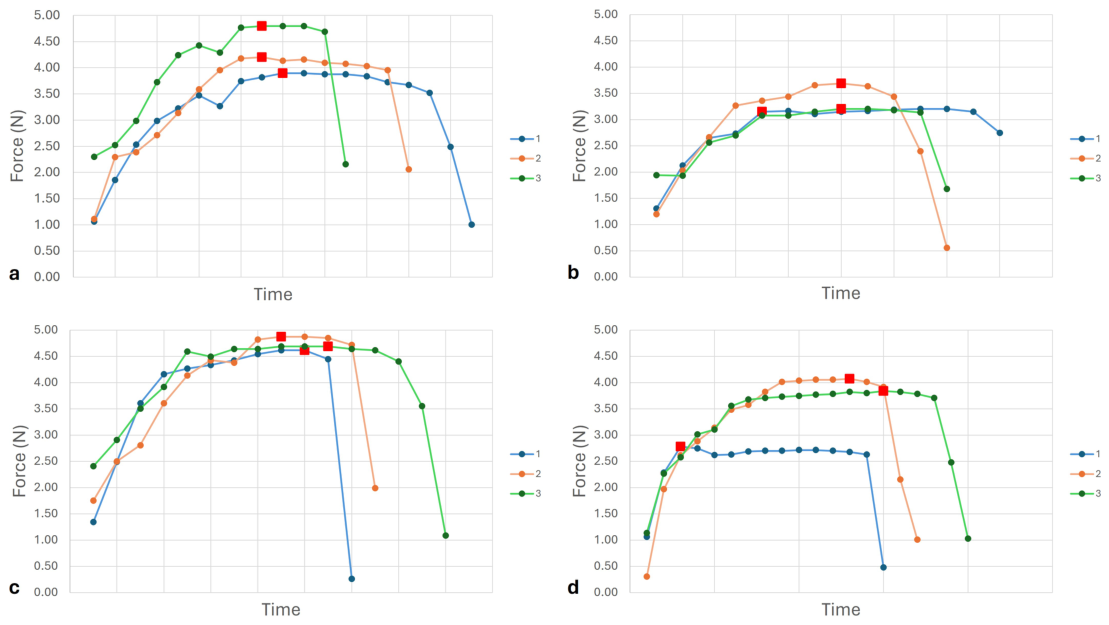
This explains the sharp drops in force shown in Figure 12. It was also not possible to repeatably increase the pressure linearly over a given time for each repeat using this method, and so the time axes pictured in Figure 12 can be considered arbitrary. Red square markers are used to indicate at which point the actuation pressure reached 2 bar for each repeat.
For this reason, tests for the maximum bending angle were repeated three times for each rod and an average value was calculated. The maximum bending angles for the SBCA configured with each rod and pressurised to 2 bar are listed in Table 3. As expected, the control rod has the smallest bending angle (59°) due to its constant thickness, increasing its bending resistance. The largest bending angle is experienced by the tapered rod and is 77°. This is unsurprising as tapered structures have been used throughout history to achieve desirable bending characteristics such as fishing rods or the limbs of a bow. The tapered, 1-joint and 2-joint rods all offer advantages over the similarly sized SBCAs presented in [13,14], which have a maximum bending angle of 72° at 4 bar and 25° at 5 bar, respectively. It is important to note that both SBCAs presented use much stronger elastomeric ribbons to splay the fingers of their grippers and are thus likely to experience larger resistance forces during actuation. However, achieving high bending angles with the proposed SBCA at comparatively low pressures is still a significant result, demonstrating that design variations of the reinforcing rod can change the bending resistance experienced by the SBCA and, by facilitating high bending angles and low pressures, could decrease the operating cost of the proposed gripper.

4.2. Force Characteristics

The fingertip force generated by the SBCA was evaluated using a blocked force test. The actuator was fixed in position, and a force-sensitive resistor was placed at the fingertip contact point. Pressure was gradually increased to 2 bar and then released to assess both loading behaviour and potential hysteresis effects.
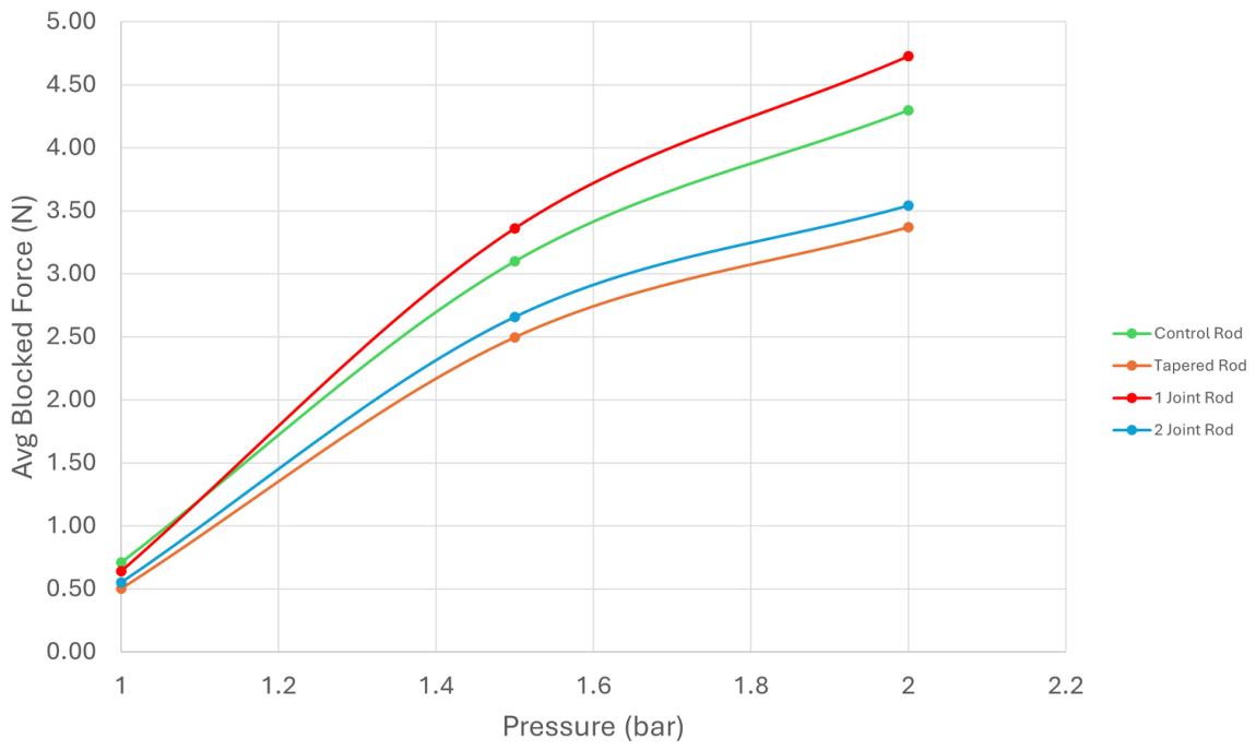
The results reveal a clear dependence of force output on reinforcing rod geometry. The 1-joint rod achieved the highest maximum fingertip force of 4.73 N at 2 bar, representing the most effective balance between structural support and compliance. The thicker base region provides resistance to axial contraction, enabling efficient force transmission, while the localised thinning reduces bending resistance.
In contrast, the tapered rod produced the lowest maximum force (3.37 N), indicating that while reduced stiffness enhances curvature, it can compromise load-bearing capability due to increased susceptibility to buckling. The control rod exhibited moderate force output, benefiting from uniform stiffness but limited by reduced curvature. The 2-joint rod demonstrated lower and less consistent force generation, likely due to stress concentrations and reduced structural integrity at multiple thinned sections.
All configurations exhibited nonlinear force–pressure relationships, consistent with the intrinsic behaviour of pneumatic soft actuators. Variations between repeated trials were attributed to non-uniform pressure application and minor mechanical effects such as initial rod seating or braid slippage during early actuation cycles.
Average blocked forces for each rod at 1 bar, 1.5 bar and 2 bar were recorded to establish a pressure–force relationship. Smooth curves are generated between the points and presented in Figure 13. All four rods behave non-linearly, which is expected due to the nature of the SBCA, posing challenges for the control of the finger. To mitigate the effects of the non-uniform pressure changes in the blocked force test and provide potential for accurate position control, a regulator such as the one presented in [28] could be considered.

4.3. Gripper-Level Performance Evaluation

To evaluate the system-level performance of the proposed actuator, a three-finger soft gripper was developed and tested on a range of objects with varying shapes, sizes, and mechanical properties. Experiments were conducted at a constant operating pressure of 1.5 bar using open-loop pressure control.

4.3.1. Grasp Success Rate and Repeatability

Grasping trials were repeated multiple times for each object to assess repeatability. A successful grasp was defined as the ability of the gripper to securely hold and lift the object without slippage for at least 5 s.
Across all tested objects, high success rates were observed for medium-to-large objects with regular geometries such as a cube, sphere, and cylinder. Consistent trends were observed across repeated trials, indicating reliable grasping behaviour under similar conditions as shown in Figure 10.

4.3.2. Payload Capacity

The gripper demonstrated the ability to lift a range of objects of varying weights. Heavier objects required increased deformation and contact area for stable grasping, which was facilitated by the compliant nature of the actuator. The maximum payload capacity was not systematically quantified; however, experimental observations indicate that objects within the tested range could be reliably manipulated at the operating pressure used.

4.3.3. Adaptive Grasping Behaviour

The gripper exhibited adaptive grasping behaviour across a variety of object geometries. Similar adaptive grasping capabilities have been reported in recent modular soft robotic systems that exploit compliant morphology to achieve robust interaction with diverse object shapes [30,31,32]. For larger or irregular objects, the fingers demonstrated coordinated deformation, including lateral deflection and partial helical wrapping, allowing the gripper to conform to object surfaces. For softer objects, such as fruit, the actuator maintained sufficient compliance to avoid visible damage during handling.
These behaviours highlight the ability of the system to achieve stable grasps without the need for precise object modelling or trajectory planning.

4.3.4. Control Considerations

The current implementation employs open-loop pressure control without active sensing or feedback. While this enables simple operation, it limits the ability to precisely regulate grasp force or finger position. Therefore, the claim of operation “without complex control or grasp planning” should be interpreted in the context of qualitative adaptability rather than precise or optimal manipulation.
Future work will focus on incorporating closed-loop control through integrated sensing, enabling improved repeatability, force regulation, and object recognition.

4.4. Measurement Limitations, Hysteresis, and Dynamic Effects

The experimental results presented Figure 12 were obtained using manual pressure regulation and a low-resolution analogue pressure gauge as detailed in Figure 7. While this setup is sufficient for identifying general performance trends and comparative behaviour between configurations, it introduces limitations in measurement precision, repeatability, and dynamic characterisation.
In particular, the manual regulation of pressure resulted in small fluctuations and non-uniform pressure increments during testing. This affects the accuracy of recorded bending angles and force values, especially when comparing closely spaced operating points. Additionally, the time-dependent response of the actuator could not be systematically controlled, making it difficult to isolate transient behaviour.
A pressure dead band was consistently observed, with actuation initiating at approximately 0.25 bar. This behaviour is attributed to the initial expansion of the bladder required to establish contact with the braided sleeve before contraction and bending can occur. Although this phenomenon was qualitatively identified, its precise magnitude may vary depending on assembly tolerances and material properties.
Hysteresis effects were also observed during loading and unloading cycles in the blocked force tests, particularly in cases where pressure release occurred rapidly. These effects are likely caused by internal friction between the bladder and braid, viscoelastic behaviour of the elastomeric materials, and minor slippage within the actuator structure. However, due to limitations in pressure control and sensing resolution, a quantitative hysteresis loop analysis could not be reliably established.
Similarly, repeatability across trials was influenced by factors such as manual pressure adjustment, initial seating of the reinforcing rod, and minor variations in assembly. While overall trends in bending and force behaviour remained consistent, variability between individual measurements highlights the need for more controlled experimental conditions.
Finally, the dynamic response of the actuator, including actuation speed, time constants, and frequency-dependent behaviour, was not explicitly characterised in this study. These parameters are important for applications requiring precise or high-speed control and are expected to be influenced by both pneumatic supply conditions and structural properties of the actuator.

4.5. Performance Trade-Off and Tunability

A key outcome of this study is the identification of a clear trade-off between bending curvature and force generation, governed by reinforcing rod geometry. Configurations that maximise bending (e.g., tapered rod) exhibit reduced force output, while those that enhance force transmission (e.g., 1-joint rod) maintain moderate curvature.
This trade-off demonstrates that actuator performance can be systematically tuned by selecting appropriate reinforcement geometries. Similar trends have recently been reported in modular and variable-stiffness soft robotic systems, where structural reconfiguration enables task-dependent adaptation of stiffness and deformation behaviour [32]. For instance, applications requiring high adaptability and object conformity may benefit from tapered designs, whereas tasks involving higher payloads may favour jointed or uniform rods.
Importantly, this tunability is achieved without modifying the actuator body. The ability to interchange reinforcing elements provides a practical mechanism for exploring and exploiting performance trade-offs within a single actuator platform, representing a key advantage over conventional SBCA designs.

5. Discussion

5.1. Fatigue Behaviour and Durability Considerations

While the proposed SBCA demonstrates reliable performance under short-term experimental conditions, its long-term durability under cyclic loading remains an important consideration for practical deployment. In particular, the modular interface introduced in this work—comprising 3D-printed end fittings and interchangeable reinforcing rods—introduces potential failure modes that differ from conventional permanently bonded designs.
The use of PLA for the reinforcing rods and structural components, while advantageous for rapid prototyping, may further limit fatigue resistance due to its relatively low toughness and susceptibility to crack propagation under cyclic loading. Additionally, repeated insertion and removal of the rods may introduce wear at the contact interfaces, potentially affecting alignment and load transfer over time.
Despite these considerations, the modular design also offers advantages for maintenance and serviceability. Unlike conventional SBCAs, where failure of the reinforcing element typically requires destructive disassembly, the proposed system enables rapid replacement of worn components, thereby extending the functional lifespan of the actuator at the system level.
Future work will focus on systematic fatigue testing under cyclic pressure conditions to quantify actuator lifespan and identify dominant failure modes. The use of alternative materials (e.g., nylon, fibre-reinforced polymers, or flexible composites) and improved interface designs will also be investigated to enhance durability and reliability for long-term operation.

5.2. Integration of Sensing for Closed-Loop Control

The current study focuses on open-loop actuation; however, the integration of embedded or surface-mounted flexible sensors represents a natural extension of the proposed design. The modular structure of the SBCA provides convenient locations for sensor placement, such as along the actuator backbone or at the fingertip interface.
Flexible strain or bend sensors could be used to directly measure actuator curvature, enabling closed-loop control of finger position and improving repeatability under varying load conditions. Recent flexible curvature sensing approaches have demonstrated accurate shape estimation for soft robotic systems while maintaining compliance [33].
Such sensing capabilities would be particularly beneficial given the nonlinear and hysteretic behaviour observed in the actuator, where precise position or force control is difficult to achieve using pressure regulation alone. By combining the proposed reconfigurable actuator design with integrated sensing, it would be possible to develop more intelligent soft grippers capable of both adaptive morphology and feedback-driven manipulation.
Future work will explore the integration of low-cost flexible sensors and their use in closed-loop control architectures for enhanced functionality and autonomy.

6. Conclusions

In this work, a low-cost, easy-to-manufacture self-bending contraction actuator (SBCA) is proposed. The highlight of the proposed SBCA is the 3D-printed novel end fittings that facilitate the non-destructive replacement of the reinforcing rod. Four design variations of the reinforcing rod are proposed and analysed, and a detailed description of the inner workings and fabrication of the SBCA is presented. An investigation into the safe operating pressure of the SBCA is conducted, as well as a comparative study on the effects of reinforcing rod design on the bending angle and fingertip force of the SBCA. The results of this study demonstrate that design variation of the reinforcing rod can influence the maximum bending angle and fingertip force of the SBCA for a given pressure. The proposed 1-joint rod achieves a bending angle and maximum fingertip force 25.42% and 10% higher, respectively, compared to the control rod, resulting in the best overall performance of the four rods. A pressure vs. force relationship is also established for each of the four proposed rods. The kinematics for the bending of the SBCA are presented and the calculated values compared to those obtained through experimentation. The paper then presented a three-finger soft gripper using the proposed SBCA. The gripper was shown to achieve successful grasps on a wide range of objects of varying sizes and mechanical properties, demonstrating its ability to conform to the object’s shape without the need for complex control or grasp planning. The maximum mass successfully grasped by the gripper was a 106 g cylinder, but further investigation into the maximum payload of the gripper for different object shapes and sizes is required. The potential for future works includes adaptation of the novel end fitting design to allow experimentation with reinforcing rods of a wider range of cross sections or construction materials. Future works should also consider the fastening methods used in [34], where the braided sleeve is folded back on itself with a ring of material inside, effectively creating another raised ring portion and preventing the braid from slipping under the zip tie. This will allow investigation into the behaviour of the proposed SBCA at higher actuation pressures. Related developments in autonomous pneumatic control [35], high-force printable pneumatic structures [36], pneumatic-muscle modelling [37], variable-stiffness soft-gripper architectures [38], and flexible sensing for soft robots [39] further demonstrate the potential for improving the controllability, adaptability and functionality of pneumatic soft robotic systems.


Author Contributions

Conceptualization, S.D.; Methodology, R.D., S.K. and S.D.; Software, R.D. and S.K.; Validation, R.D., S.K. and S.D.; Formal analysis, R.D. and S.K.; Investigation, R.D. and S.K.; Resources, S.K.; Writing—original draft, R.D. and S.K.; Writing—review & editing, S.K. and S.D.; Visualization, R.D.; Supervision, S.N.-M. and S.D.; Project administration, S.D. All authors have read and agreed to the published version of the manuscript.

Funding

This research received no external funding.

Institutional Review Board Statement

Not applicable.

Informed Consent Statement

Not applicable.

Data Availability Statement

The raw data supporting the conclusions of this article will be made available by the authors on request.

Acknowledgments

Authors would like to thank Hamid Isakhani for his valuable support, advice and interest in the project, Pooria Ghavam for the facilities and support provided at the lab, and James Chandler for his technical support in the Makerspace.

Conflicts of Interest

The authors declare no conflicts of interest.

Appendix A

Appendix A.1. Limitations of the Model

The proposed kinematic model provides a simplified geometric approximation of the bending behaviour of the SBCA; however, several limitations affect its predictive accuracy. The model assumes that the actuator follows an ideal constant-curvature arc as shown in Figure A1, which does not fully capture the true deformation profile observed experimentally. In practice, the bending is often non-uniform due to variations in material properties and internal interactions.
Figure A1. Diagram of bending muscle geometry.
Actuators 15 00434 g0a1
A key limitation is the neglect of the hyperelastic behaviour of the elastomeric bladder. Under pressurisation, the bladder exhibits nonlinear stress–strain characteristics, which influence both radial expansion and axial contraction, and consequently the overall curvature. Additionally, frictional effects between the braided sleeve and the bladder, as well as inter-fibre friction within the braid, are not considered. These frictional forces resist motion and reduce the achievable bending angle.
The model also does not account for the mechanical contribution of the reinforcing rod, whose stiffness and geometry play a dominant role in determining bending resistance. Furthermore, contact interactions between the rod, bladder, and braid redistribute internal forces during actuation, leading to deviations from the assumed idealised behaviour.
Experimental uncertainties provide another source of error. In particular, the measurement of the braid angle during actuation is challenging and may introduce inaccuracies into the model parameters.
As a result of these simplifications, a deviation of approximately 31% between the predicted and experimental bending angles is observed. The current model should therefore be regarded as a first-order analytical tool that provides qualitative insight into actuator behaviour rather than a fully predictive model. Future work should incorporate hyperelastic material models, frictional effects, and coupled structural interactions to improve the accuracy and applicability of the model.

Appendix A.2. Grasp Test

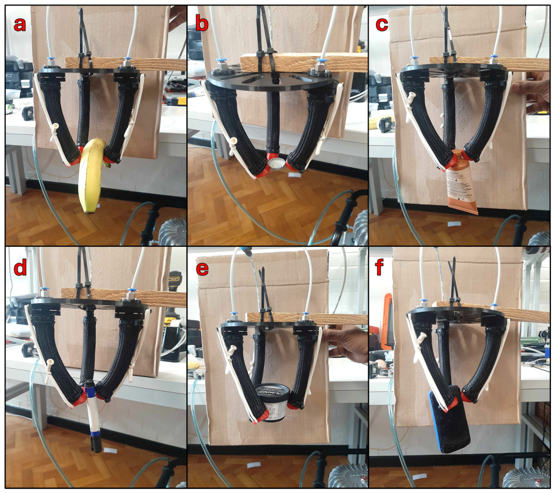
Figure A2 shows the gripper grasping each item. All items were grasped successfully on the first try except for the bottle cap, which required 3 attempts. Once the tests were completed, the banana was inspected for damage to the skin or bruising, but no such damage was observed, demonstrating the compliant and adaptive properties of the gripper. Another good example of the gripper’s compliance can be seen in Figure A2c. Due to the larger diameter of the pot, the SBCAs cannot continue to bend in a straight line, instead deflecting to the side, resulting in a helical-shaped yet robust grasp.
Figure A2. A three-finger gripper using the proposed SBCA grasping (a) a banana, (b) a bottle cap, (c) a tube of cream, (d) a whiteboard pen, (e) a pot, and (f) a whiteboard rubber.
Actuators 15 00434 g0a2

Appendix A.3. Destructive Failure Test

The current SBCA prototype was developed primarily to evaluate actuator reconfigurability and comparative mechanical behaviour rather than long-term operational durability. As a result, cyclic fatigue behaviour, leakage progression, and structural degradation under repeated actuation were not systematically characterised. The modular assembly approach, including 3D-printed interfaces, zip tie fastening, and elastomeric sealing, may introduce long-term reliability concerns such as creep, stress relaxation, seal degradation, and pressure leakage during extended operation. Although a destructive pressure test was conducted to identify approximate structural limits, comprehensive lifecycle and fatigue analysis remain important areas for future investigation. Future work will focus on cyclic durability testing, leakage quantification, and improved sealing and fastening strategies for enhanced long-term actuator reliability.
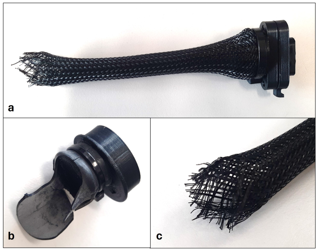
Figure A3. Images of (a) the failed SBCA, (b) the fingertip and ruptured bladder, and (c) a zoomed-in view of the failed braid.
Actuators 15 00434 g0a3

References

  1. Fantoni, G.; Santochi, M.; Dini, G.; Tracht, K.; Scholz-Reiter, B.; Fleischer, J.; Lien, T.K.; Seliger, G.; Reinhart, G.; Franke, J.; et al. Grasping devices and methods in automated production processes. CIRP Ann. 2014, 63, 679–701. [Google Scholar] [CrossRef]
  2. Samadikhoshkho, Z.; Zareinia, K.; Janabi-Sharifi, F. A Brief Review on Robotic Grippers Classifications. In Proceedings of the 2019 IEEE Canadian Conference of Electrical and Computer Engineering (CCECE), Edmonton, AB, Canada, 5–8 May 2019. [Google Scholar] [CrossRef]
  3. Li, M.; Pal, A.; Aghakhani, A.; Pena-Francesch, A.; Sitti, M. Soft actuators for real-world applications. Nat. Rev. Mater. 2022, 7, 235–249. [Google Scholar] [PubMed]
  4. Shintake, J.; Cacucciolo, V.; Floreano, D.; Shea, H. Soft robotic grippers. Adv. Mater. 2018, 30, 1707035. [Google Scholar] [CrossRef] [PubMed]
  5. Trivedi, D.; Rahn, C.D.; Kier, W.M.; Walker, I.D. Soft robotics: Biological inspiration, state of the art, and future research. Appl. Bionics Biomech. 2008, 5, 99–117. [Google Scholar] [CrossRef]
  6. Ilievski, F.; Mazzeo, A.D.; Shepherd, R.F.; Chen, X.; Whitesides, G.M. Soft robotics for chemists. Angew. Chem. Int. Ed. 2011, 50, 1890–1895. [Google Scholar] [CrossRef] [PubMed]
  7. Shepherd, R.F.; Ilievski, F.; Choi, W.; Morin, S.A.; Stokes, A.A.; Mazzeo, A.D.; Chen, X.; Wang, M.; Whitesides, G.M. Multigait soft robot. Proc. Natl. Acad. Sci. USA 2011, 108, 20400–20403. [Google Scholar] [CrossRef] [PubMed]
  8. Marchese, A.D.; Komorowski, K.; Onal, C.D.; Rus, D. Design and control of a soft and continuously deformable 2D robotic manipulation system. In Proceedings of the IEEE International Conference on Robotics and Automation; IEEE: Piscataway, NJ, USA, 2014; pp. 2189–2196. [Google Scholar] [CrossRef]
  9. Andrikopoulos, G.; Nikolakopoulos, G.; Stamatis, M. A Survey on Applications of Pneumatic Artificial Muscles. In Proceedings of the 19th Mediterranean Conference on Control & Automation (MED); IEEE: Piscataway, NJ, USA, 2011. [Google Scholar] [CrossRef]
  10. Kalita, B.; Leonessa, A.; Dwivedy, S.K. A Review on the Development of Pneumatic Artificial Muscle Actuators: Force Model and Application. Actuators 2022, 11, 288. [Google Scholar] [CrossRef]
  11. Mohseni, O.; Gagey, F.; Zhao, G.; Seyfarth, A.; Sharbaf, M.A. How far are Pneumatic Artificial Muscles from biological muscles? In Proceedings of the IEEE International Conference on Robotics and Biomimetics, Florence, Italy, 6–9 December 2020. [Google Scholar]
  12. Davis, S.; Caldwell, D.G. Braid effects on contractile range and friction modeling in pneumatic muscle actuators. Int. J. Robot. Res. 2006, 25, 359–369. [Google Scholar] [CrossRef]
  13. Al-Ibadi, A.; Nefti-Meziani, S.; Davis, S. Active Soft End Effectors for Efficient Grasping and Safe Handling. IEEE Access 2018, 6, 23591–23601. [Google Scholar] [CrossRef]
  14. Al-Ibadi, A.; Nefti-Meziani, S.; Davis, S. Design, kinematics and controlling a novel soft robot arm with parallel motion. Robotics 2018, 7, 19. [Google Scholar] [CrossRef]
  15. Antonelli, M.; Dall’Alba, D.; Gerboni, G. Mechanical Design, Manufacturing, and Testing of a Soft Pneumatic Actuator with a Reconfigurable Modular Reinforcement. Robotics 2024, 13, 165. [Google Scholar] [CrossRef]
  16. Connolly, F.; Polygerinos, P.; Walsh, C.J.; Bertoldi, K. Mechanical programming of soft actuators by varying fiber angle. Soft Robot. 2015, 2, 26–32. [Google Scholar] [CrossRef]
  17. Overvelde, J.T.B.; Kloek, T.; D’haen, J.J.A.; Bertoldi, K. Amplifying the response of soft actuators by harnessing snap-through instabilities. Proc. Natl. Acad. Sci. USA 2016, 113, 10863–10868. [Google Scholar]
  18. Pagliocca, G.; Bianchi, M.; Catalano, M.G.; Grioli, G. Modular Reconfigurable Rotary Style Soft Pneumatic Actuators. Sens. Actuators A Phys. 2024, 380, 115746. [Google Scholar]
  19. Gregov, G.; Vuković, T.; Gašparić, L.; Pongrac, M. Development, Experimental Assessment, and Application of a Vacuum-Driven Soft Bending Actuator. Appl. Sci. 2025, 15, 2557. [Google Scholar] [CrossRef]
  20. Polygerinos, P.; Wang, Z.; Galloway, K.C.; Wood, R.J.; Walsh, C.J. Soft robotic glove for combined assistance and at-home rehabilitation. Robot. Auton. Syst. 2015, 73, 135–143. [Google Scholar] [CrossRef]
  21. Mosadegh, B.; Polygerinos, P.; Keplinger, C.; Wennstedt, S.; Shepherd, R.F.; Gupta, U.; Shim, J.; Bertoldi, K.; Walsh, C.J.; Whitesides, G.M. Pneumatic Networks for Soft Robotics that Actuate Rapidly. Adv. Funct. Mater. 2014, 24, 2163–2170. [Google Scholar] [CrossRef]
  22. Gorissen, B.; Reynaerts, D.; Konishi, S.; Yoshida, K.; Kim, J.-W.; De Volder, M. Elastic Inflatable Actuators for Soft Robotic Applications. Adv. Mater. 2017, 29, 1604977. [Google Scholar] [CrossRef] [PubMed]
  23. Do Rosario Carvalho, A.D.; Karanth, N.P.; Desai, V. Design and characterization of a pneumatic muscle actuator with novel end-fittings for medical assistive applications. Sens. Actuators A Phys. 2021, 331, 112877. [Google Scholar] [CrossRef]
  24. Deimel, R.; Brock, O. A novel type of compliant and underactuated robotic hand for dexterous grasping. Int. J. Robot. Res. 2016, 35, 161–185. [Google Scholar] [CrossRef]
  25. Wang, X.; Kang, H.; Zhou, H.; Au, W.; Wang, M.Y.; Chen, C. Development and evaluation of a robust soft robotic gripper for apple harvesting. Comput. Electron. Agric. 2023, 204, 107552. [Google Scholar] [CrossRef]
  26. Warren, M. Installation Press for Heat Set Inserts. 2021. Available online: https://egrove.olemiss.edu/honthesis (accessed on 27 April 2026).
  27. Zhou, J.; Chen, S.; Wang, Z. A Soft-Robotic Gripper with Enhanced Object Adaptation and Grasping Reliability. IEEE Robot. Autom. Lett. 2017, 2, 2287–2293. [Google Scholar] [CrossRef]
  28. Dudić, S.; Reljić, V.; Šešlija, D.; Dakić, N.; Blagojević, V. Improving energy efficiency of flexible pneumatic systems. Energies 2021, 14, 1819. [Google Scholar] [CrossRef]
  29. Al-Fahaam, H.; Davis, S.; Nefti-Meziani, S. Power Assistive and Rehabilitation Wearable Robot based on Pneumatic Soft Actuators. In Proceedings of the Methods and Models in Automation and Robotics (MMAR), Międzyzdroje, Poland, 9 August–1 September 2016. [Google Scholar]
  30. Jiang, Y.; Li, Z.; Wang, H.; Shepherd, R.F. A Reconfigurable Soft Linkage Robot via Internal Virtual Joints. Soft Robot. 2024, 11, 946–957. [Google Scholar] [CrossRef] [PubMed]
  31. Knospler, J.; Xue, W.; Trkov, M. Reconfigurable Modular Soft Robots with Modulating Stiffness and Versatile Task Capabilities. Smart Mater. Struct. 2024, 33, 065040. [Google Scholar] [CrossRef]
  32. Luan, Y.; Chen, X.; Li, Y.; Zhao, Q. Variable Stiffness Fibers Enabled Universal and Programmable Re-Foldability Strategy for Modular Soft Robotics. Adv. Sci. 2024, 11, 24070056. [Google Scholar] [CrossRef] [PubMed]
  33. Benarrait, D.; Ozel, S.; Rus, D. A Flexible Double-Sided Curvature Sensor Array for Use in Soft Robotics. Sensors 2024, 24, 3475. [Google Scholar] [CrossRef] [PubMed]
  34. Giannaccini, M.E.; Xiang, C.; Atyabi, A.; Theodoridis, T.; Nefti-Meziani, S.; Davis, S. Novel Design of a Soft Lightweight Pneumatic Continuum Robot Arm with Decoupled Variable Stiffness and Positioning. Soft Robot. 2018, 5, 54–70. [Google Scholar] [CrossRef] [PubMed]
  35. Rothemund, P.; Ainla, A.; Belding, L.; Preston, D.J.; Kurihara, S.; Suo, Z.; Whitesides, G.M. A soft, bistable valve for autonomous control of soft actuators. Sci. Robot. 2018, 3, eaar7986. [Google Scholar] [CrossRef] [PubMed]
  36. Yap, H.K.; Ng, H.Y.; Yeow, R.C.H. High-force soft printable pneumatics for soft robotic applications. Soft Robot. 2017, 4, 244–255. [Google Scholar] [CrossRef]
  37. Kelasidi, E.; Andrikopoulos, G.; Nikolakopoulos, G.; Manesis, S. A Survey on Pneumatic Muscle Actuators Modeling. In Proceedings of the 2011 IEEE International Symposium on Industrial Electronics, Gdansk, Poland, 27–30 June 2011. [Google Scholar]
  38. Al Abeach, L.; Nefti-Meziani, S.; Theodoridis, T.; Davis, S. A Variable Stiffness Soft Gripper Using Granular Jamming and Biologically Inspired Pneumatic Muscles. J. Bionic Eng. 2018, 15, 236–246. [Google Scholar] [CrossRef]
  39. Qu, M.; Zhang, Y.; Liu, X.; Wang, Z.; Zhao, H. Advanced Flexible Sensing Technologies for Soft Robots. Adv. Funct. Mater. 2024, 34, 2401311. [Google Scholar] [CrossRef]
Figure 1. The basic structure of the two actuators used in this study. (a) Basic structure of a pneumatic muscle actuator (PMA). (b) Structure of a self-bending contraction actuator (SBCA).
Actuators 15 00434 g001
Figure 2. Side profiles of the investigated reinforcing rods: (a) Control Rod, (b) Tapered Rod, (c) 1-Joint Rod, (d) 2-Joint Rod.
Actuators 15 00434 g002
Figure 3. A cross section of the SBCA assembled with a 2 Joint Rod.
Actuators 15 00434 g003
Figure 4. SBCA CAD design of rigid components: (a) single SBCA finger on gripper palm, (b) clamp plate used to fix fingers to palm, (c) structure of the proposed SBCA finger, (d) novel fingertip, (e) novel finger base.
Actuators 15 00434 g004
Figure 5. FEA bending analysis of the (a) Control, (b) Tapered, (c) 1-Joint and (d) 2-Joint reinforcing rods.
Actuators 15 00434 g005
Figure 6. Construction of (a) inner bladder, (b) braided sleeve, (c) fully constructed SBCA finger, (d) threaded inserts in finger base, and (e) 3D-printed finger base and tip.
Actuators 15 00434 g006
Figure 7. Schematic diagram of the control system architecture with the components in the used configuration and connection of the experimental system.
Actuators 15 00434 g007
Figure 8. Blocked force test rig with a fixed Alpha MF01A-N-221-A05 round force-sensitive resistor to a frame and SBCA clamped to a bench vice.
Actuators 15 00434 g008
Figure 9. Assembled gripper with side, bottom and top views (ac). (d) Arduino Uno connected to an Alpha MF01A-N-221-A05 round force-sensitive resistor (FSR) and a SpectraSymbol long flex sensor to record the respective values during the experiments. (e) Gems 3500 Series Pressure Transducer, from Gems Sensors, China and (f) SMC Push Button Pneumatic Manual Control Valve VZM500, from SMC, Japan.
Actuators 15 00434 g009
Figure 10. A three-finger gripper using the proposed SBCA grasping: (a) a 3D-printed cube, (b) a sphere, (c) a cylinder.
Actuators 15 00434 g010
Figure 11. Reachable work volume of the SBCA at 1 bar, 1.5 bar, and 2 bar for the (a) Control, (b) Tapered, (c) 1-Joint, and (d) 2-Joint rods.
Actuators 15 00434 g011
Figure 12. Fingertip force over time for the proposed SBCA configured with the (a) Control, (b) Tapered, (c) 1-Joint, and (d) 2-Joint reinforcing rods to a maximum pressure of 2 bar.
Actuators 15 00434 g012
Figure 13. Force vs. Pressure of the proposed SBCA for the four proposed reinforcing rods.
Actuators 15 00434 g013
Table 1. Comparison of soft actuators.
ReferenceActuation TypeMax Bending AngleFingertip ForcePressure RangeReconfigurableKey Feature
Goran Gregov et al. (2025) [19]Vacuum-driven∼90°∼3–5 NNegative pressureNoStable bending via vacuum chambers
Polygerinos et al. (2015) [20]Pneumatic > 180 ModeratePositive pressureNoFibre-reinforced actuators
Mosadegh et al. (2014) [21]Pneumatic∼90–120°Low–moderatePositive pressureNoMulti-material soft actuators
Gorissen et al. (2017) [22]PneumaticLarge curvatureLowPositive pressureNoProgrammable shape morphing
This workPneumatic (SBCA)77°4.73 N0–2 barYesTunable via interchangeable rods
Table 2. FEA simulation results for the 4 proposed reinforcing rods.
RodMin Safety FactorMax Deflection (mm)
Control6.9322
Tapered2.2038
1 Joint1.7526
2 Joint1.3838
Table 3. Maximum bending angle of the SBCA at 2 bar for the four proposed reinforcing rods.
Reinforcing RodMaximum Bending Angle (°)
Control59
Tapered77
1 Joint74
2 Joint73
Disclaimer/Publisher’s Note: The statements, opinions and data contained in all publications are solely those of the individual author(s) and contributor(s) and not of MDPI and/or the editor(s). MDPI and/or the editor(s) disclaim responsibility for any injury to people or property resulting from any ideas, methods, instructions or products referred to in the content.