Article

Multi-UAV Bearing-Only Active Tracking via Prescribed-Shell Bearing-Geometry Self-Organization

1
Center for Aerospace Integration Technology, Binzhou Institute of Technology, Binzhou 256600, China
2
School of Mechanical Engineering, Shandong University, Jinan 250061, China
3
School of Astronautics, Northwestern Polytechnical University, Xi’an 710072, China
4
Department of Precision Instrument, Tsinghua University, Beijing 100084, China
*
Author to whom correspondence should be addressed.
Actuators 2026, 15(7), 365; https://doi.org/10.3390/act15070365
Submission received: 27 May 2026 / Revised: 15 June 2026 / Accepted: 20 June 2026 / Published: 2 July 2026
(This article belongs to the Section Aerospace Actuators)

Abstract

In multi-UAV bearing-only active tracking, the estimation and control performance is fundamentally determined by the target-centered bearing geometry, as passive angle-of-arrival measurements provide directional information without direct range information. To overcome this limitation, this paper formulates the problem as prescribed-shell bearing-geometry self-organization, in which the radial sensing scale is regulated to an admissible shell while the angular bearing distribution is actively reshaped on that shell. A shell-compatible moment–volume bearing-enclosure potential is first constructed directly on unit bearing directions, decoupling angular geometry improvement from unsafe range reduction and encoding directed balance, angular isotropy, and noncoplanar enclosure. To realize the resulting direction-space descent via physical UAV motion, a radius-normalized tangential lifting mechanism is derived from bearing-direction kinematics, eliminating radius-dependent angular-rate bias. The nominal radial–tangential command is then executed through a bearing-geometry-preserving ECBF-QP that embeds a predefined-time radial shell-reaching constraint, enforces target standoff, inter-UAV separation, and input constraints, and preserves shell reaching and tangential geometry improvement whenever feasible. Closed-loop analysis establishes shell reaching, practical bearing-geometry descent, safety forward invariance, and signal boundedness. Finally, improved bearing geometry, prescribed-shell convergence, preserved safety margins, reduced disruption from safety filtering, and real-world implementability are demonstrated via simulations, ablation studies, ROS-based validation, and a real-world flight experiment, which provide a promising approach for multi-UAV bearing-only active tracking.

1. Introduction

Bearing-only sensing is attractive for aerial target tracking because it can be implemented with lightweight passive sensors and does not require active range transmission. Once a target is detected by an onboard camera or angle-of-arrival (AOA) sensor, the relative direction can be obtained, whereas the relative distance remains unmeasured. This absence of range makes bearing-only tracking intrinsically geometry-dependent: the estimation quality is determined not only by the sensor noise, but also by the target-centered relative motion and line-of-sight configuration [1,2,3]. Thus, bearing-only active tracking is not merely a trajectory-tracking problem, but an active perception problem in which sensing geometry, motion generation, estimation, and safety constraints are tightly coupled.
In multi-UAV bearing-only tracking, multiple simultaneous bearings provide spatial sensing redundancy. However, redundancy in the number of observers does not automatically imply an informative bearing geometry. If the target-centered bearing directions are nearly redundant, strongly anisotropic, weakly exciting along certain spatial directions, or trapped in unfavorable angular layouts, the cooperative localization problem may remain ill-conditioned. Therefore, the essential difficulty is not only to keep a team of UAVs following a maneuvering target, but also to organize their target-centered bearing directions into an informative spatial configuration while maintaining a prescribed sensing scale and hard safety margins.
Beyond bearing-only tracking, recent studies on intelligent control, cooperative autonomy, and optimization-driven multi-agent systems have advanced the robustness, scalability, and decision-making capability of UAV and robotic networks. Distributed optimization, resilient coordination, trajectory optimization, robust predictive control, and learning-assisted decision-making have been used to improve autonomous operation in uncertain and networked environments [4,5,6,7,8,9,10]. These developments provide a broader cooperative-autonomy context for the present study. The problem considered here is complementary to this line of research: it focuses on the target-centered sensing geometry created by simultaneous bearing-only measurements and on how this geometry can be actively organized on an admissible sensing shell under safety-critical constraints.
Existing studies on bearing-only target localization, motion estimation, and target following have established several important foundations. Bearing-only filtering methods estimate target states from nonlinear AOA measurements and observer motion through Kalman-filter variants, modified coordinate representations, pseudolinear filtering, Gaussian-mixture filtering and track initiation techniques [1,2,11,12]. Recent visual-measurement formulations further show that additional image information, such as bounding-box induced bearing-angle measurements, can improve observability without relying solely on lateral excitation [13]. Cooperative bearing-only estimation has also been revisited recently through spatial–temporal triangulation for vision-based aerial target pursuit [14]. These results improve the estimation side of bearing-only tracking, but they do not directly address how a multi-UAV team should actively reshape its simultaneous bearing directions under prescribed radial sensing and safety-critical execution constraints.
Motion design is another central route to improve bearing-only observability. Observer maneuver optimization, trajectory optimization, circumnavigation, weaving maneuvers, and helical guidance laws generate line-of-sight variation and have been shown to enhance the observability of a target observed through bearing-only measurements [15,16,17,18,19]. In particular, three-dimensional observability-enhanced helical guidance demonstrates that target-relative angular motion can be deliberately designed to improve bearing-only following performance [18]. Recent bearing-only helical homing guidance further confirms the role of 3D angular motion in observability-enhanced target interception [19]. Such methods highlight the importance of radial–tangential motion around a target. Nevertheless, most existing guidance laws rely on a single observer, a preassigned circular or helical pattern, or an observability-improving motion template. The multi-UAV problem considered here is different: the team is not required to follow a prescribed orbit. Instead, the instantaneous distribution of multiple target-centered bearing directions must self-organize on an admissible sensing shell.
Information metrics, including the Fisher information matrix (FIM), Cramér–Rao lower bound (CRLB), observability Gramian, and related spectral criteria, provide principled measures for bearing-only localization quality and sensor-geometry evaluation [20,21,22,23,24]. For AOA sensing, however, these criteria usually couple two effects: range-dependent attenuation and angular diversity [25,26]. This coupling is useful for performance evaluation, but it is not directly aligned with prescribed-shell control. If a FIM/CRLB gradient is used as a control objective, the range-dependent term may favor reducing the UAV–target distance, whereas the tracking task must maintain a safe target standoff and regulate the sensing scale to a prescribed shell. Once the radial scale is constrained by sensing and safety requirements, the remaining control-relevant quantity is the angular distribution of the unit bearing directions. This motivates a shell-compatible metric defined directly on the target-centered bearing directions.
A second difficulty appears when a direction-space objective is realized by physical UAV motion. With the target-centered decomposition p r , i = r i n i , the bearing-direction kinematics satisfy
n ˙ i = 1 r i I 3 n i n i v r , i .
Equation (1) shows that a tangent projection removes the radial component of the relative velocity, but it does not remove the 1 / r i scaling between Euclidean tangential motion and direction-space motion. Consequently, the same tangent-projected velocity induces different bearing-direction rates for UAVs located at different radii. A controller designed to decrease the angular bearing-geometry metric on ( S 2 ) N must therefore include a radius-normalized lifting from direction-space descent to Euclidean UAV motion.
Safety imposes a further constraint on active bearing-geometry improvement. A nominal geometry-improving maneuver may drive a UAV toward the target exclusion region, reduce inter-UAV separation, or require infeasible acceleration. Control barrier functions (CBFs) and exponential or high-order CBF quadratic programs provide a systematic way to enforce forward invariance of safety sets [27,28,29]. Multi-robot barrier certificates and recent graph-based CBF methods further show the importance of scalable safety enforcement in multi-agent systems [30,31,32]. However, a standard minimum-deviation ECBF-QP that penalizes only U U d 2 does not distinguish the radial component responsible for prescribed-shell reaching from the tangential component responsible for bearing-geometry improvement. As a result, safety corrections may preserve collision avoidance but delay shell reaching or unnecessarily suppress the tangential motion needed for bearing-geometry self-organization. This requires a safety execution layer that enforces hard constraints while preserving the radial and tangential roles of the nominal command whenever they are compatible with safety and input limits.
Motivated by these observations, this paper formulates multi-UAV bearing-only active tracking as a prescribed-shell bearing-geometry self-organization problem. The target-relative geometry is decomposed into a radial sensing scale and a unit bearing direction. The radial channel regulates the UAV–target distance to an admissible sensing shell, whereas the tangential channel reshapes the angular distribution of the simultaneous bearing directions on that shell. The proposed framework does not impose a preassigned circular or helical formation. Instead, it constructs a moment–volume bearing-enclosure potential on the unit bearing directions, realizes the induced direction-space descent through a radius-normalized tangential lifting mechanism, and executes the nominal radial–tangential command through a safety-critical QP. In this execution layer, the predefined-time requirement is introduced for the radial shell-reaching behavior, so that the sensing scale can be regulated within a specified time bound, while the tangential component remains available for bearing-geometry improvement. A bearing-only estimation interface provides the relative state and maneuver estimates needed by the controller, while the main focus of this paper remains the control-side bearing-geometry organization and safety-certified execution.
The main contributions are summarized as follows.
  • A shell-compatible moment–volume bearing-enclosure potential E enc is constructed on the unit bearing directions for prescribed-shell multi-UAV bearing-only active tracking. Unlike FIM/CRLB-type criteria that couple range attenuation and angular diversity, E enc is defined directly on the target-centered bearing directions after the radial sensing scale is assigned. It combines a first–second spherical moment discrepancy with a logarithmic triple-product volume barrier, thereby capturing directed balance, FIM-inspired angular isotropy, and finite-agent noncoplanar enclosure.
  • A radius-normalized tangential lifting mechanism is derived from the bearing-direction kinematics. The contribution is not the standard identity n ˙ i = ( 1 / r i ) P τ , i v r , i itself, but the use of this radius-dependent map to convert the descent induced by E enc into Euclidean UAV motion without angular-rate bias across different radii.
  • A bearing-geometry-preserving ECBF-QP, termed PT-BG-ECBF-QP, is developed for safety-critical execution. The QP embeds a predefined-time radial shell-reaching constraint, enforces target-standoff and inter-UAV ECBF constraints, and uses radial–tangential weighted allocation with a geometry-preserving close-pair term. The closed-loop analysis establishes radial shell reaching under the hard shell-CLF and QP feasibility conditions, practical descent of the bearing-geometry function V b = E enc , forward invariance of the safety set, and boundedness of the closed-loop signals.
The remainder of this paper is organized as follows. Section 2 reviews related work and formulates the multi-UAV bearing-only active tracking problem. Section 3 develops the prescribed-shell bearing-geometry controller, including the shell-compatible bearing-enclosure potential, radial shell regulation, and radius-normalized tangential lifting. Section 4 develops the PT-BG-ECBF-QP safety execution layer. Section 5 analyzes the closed-loop properties. Section 6 presents simulation studies, ROS-based validation, and a real-world flight experiment, and Section 7 concludes the paper.

2. Related Work and Problem Formulation

2.1. Bearing-Only Tracking and Observability Enhancement

Bearing-only target tracking has been extensively studied because an AOA measurement provides directional information but no direct range. Classical bearings-only target-motion analysis and filtering methods include Kalman-filter variants, modified polar or spherical coordinates, pseudolinear filtering, Gaussian-mixture filtering, particle filtering, and track-initiation techniques [1,2,3,11,12]. These methods address how to reconstruct the target state from nonlinear angular measurements and observer motion. In multi-sensor or multi-agent settings, bearing-only measurements have also been used for self-localization, velocity consensus, cooperative estimation, and multi-UAV target localization [13,14,33,34]. These studies provide the estimation foundation for bearing-only tracking, but the observer motion or team configuration is often treated as a separate design component.
Motion design is another central route to improve bearing-only observability. Optimal observer maneuvers and trajectory optimization have been studied for bearings-only localization and tracking [15,16,17]. More recently, three-dimensional observability-enhanced helical guidance has shown that deliberate target-relative angular motion can improve bearing-only target following performance in 3D space [18]. Bearing-only helical homing guidance further extends this idea to 3D homing/interception scenarios and shows that line-of-sight variation and acceleration are closely related to observability enhancement [19]. These works reveal the importance of target-relative angular motion, but they mainly concern a single observer, a prescribed guidance pattern, or an estimation-oriented maneuver.
The present work differs from these studies in its control objective. The multi-UAV team is not required to follow a preassigned circular or helical pattern. Instead, the simultaneous target-centered bearing directions are organized according to an angular bearing-geometry metric on a prescribed sensing shell. The control problem, therefore, concerns not only line-of-sight excitation, but also multi-UAV bearing-geometry self-organization under radial shell regulation, target-standoff, inter-UAV separation, and input constraints.

2.2. Information Metrics for Bearing Geometry

Information metrics provide a principled way to evaluate localization quality and sensor geometry. The Fisher information matrix (FIM), Cramér–Rao lower bound (CRLB), observability Gramian, and related spectral criteria have been used for sensor placement, active localization, target tracking, and cooperative sensing [20,21,22,23,24]. For AOA localization, optimal sensor-target geometry has also been studied from the viewpoint of angular separation and passive localization accuracy [25,26]. Recent spatial–temporal triangulation for bearing-only cooperative motion estimation further shows that explicitly exploiting bearing geometry remains important in vision-based aerial target pursuit [14]. These works demonstrate that measurement geometry is decisive for bearing-only localization performance.
However, for AOA sensing, FIM/CRLB-type criteria usually couple range-dependent attenuation and angular diversity. This coupling is meaningful for localization-performance evaluation, but it is not directly aligned with prescribed-shell control. If such metrics are used as control objectives, their range-dependent terms may favor moving closer to the target, whereas the task considered here requires the radial scale to be regulated to an admissible sensing shell and to satisfy target-standoff safety. Once the radial scale is assigned, the remaining control-relevant geometry is the angular distribution of the unit bearing directions.
Bearing-based formation and rigidity theory provide another important viewpoint for angular geometry. Bearing rigidity, bearing-based network localization, and bearing-constrained formation control characterize formation shapes using inter-agent bearings rather than distances [35,36,37,38,39]. These results are closely related to angular formation geometry, but their primary objective is formation localization, stabilization, or maneuvering under bearing constraints. In contrast, the present problem concerns the target-centered bearing distribution generated by a team of tracking UAVs. The bearing geometry is not imposed as a fixed formation; it must be shaped by tangential motion while the radial distance is regulated by the prescribed shell objective.
This perspective motivates a shell-compatible moment–volume bearing-enclosure potential. Recent bearing-only tracking and cooperative estimation studies have further emphasized the role of target-centered geometry in active perception and aerial pursuit. Three-dimensional bearing-only target following shows that deliberately designed angular motion can enhance observability in 3D space [18], while spatial–temporal triangulation for bearing-only cooperative motion estimation exploits the geometric constraints among multiple target-centered bearing measurements [14]. Recent UAV path-optimization and multisensor motion-coordination studies also confirm that the tracking or localization performance of angle-only systems is strongly affected by the sensor-target geometry [40,41]. These works motivate the use of bearing geometry as an active control variable, rather than only as an offline performance index.
Existing optimal-geometry and frame-theoretic studies provide important second-order foundations for this viewpoint. FIM/CRLB-, GDOP-, and D-optimality-based methods characterize how angular separation and sensor placement affect bearing-only localization accuracy [25,26,42]. Frame-based formulations further relate optimal angular configurations to second-order isotropy, tight-frame conditions, and gradient-based sensor-placement constructions [21,22,43]. These results explain why a well-conditioned bearing dispersion matrix is desirable. However, prescribed-shell active tracking requires a control-oriented tangential geometry that is more specific than second-order excitation alone.
In particular, different geometric quantities capture different defects of a finite target-centered bearing distribution. A first-moment or centroid-type condition can detect whether the directed bearing vectors are biased toward one side of the target, but it does not by itself guarantee balanced angular excitation. A second-order spectral or tight-frame condition can make the bearing dispersion matrix well-conditioned, but it does not by itself distinguish a true directed enclosure from a one-sided or nearly coplanar finite bearing set. A volume or encirclement-type quantity can indicate three-dimensional spread, but it does not alone encode the FIM-inspired second-order isotropy required for bearing-only localization quality. Thus, the relevant tangential objective is not a single centroid, spectral, or volume criterion. It should jointly encode directed balance, second-order angular isotropy, and finite-agent noncoplanar enclosure on the assigned sensing shell.
Accordingly, the proposed potential combines a first–second spherical moment discrepancy with a logarithmic triple-product volume barrier. This construction can be viewed as a control-oriented moment–volume extension of fixed-radius bearing-only information geometry: the moment terms inherit the balance and isotropy requirements suggested by optimal-geometry and frame-theoretic analyses, while the triple-product barrier prevents the finite UAV bearing set from collapsing into a coplanar or non-enclosing angular layout. The resulting scalar potential is defined directly on the unit bearing directions and is therefore compatible with tangential descent, radius-normalized lifting, and safety-critical execution.

2.3. Safety-Critical Control and CBF-QP Methods

Control barrier functions provide a systematic framework for enforcing state constraints through forward invariance. CBF-QP formulations modify a nominal input minimally while satisfying safety constraints, and have become a standard tool for safety-critical control [27]. For high-relative-degree constraints, exponential CBFs and high-order CBFs extend the method by constructing auxiliary barrier dynamics whose satisfaction implies invariance of the original safe set [28,29]. These tools are well-suited for target-standoff, collision avoidance, and input-constrained robotic systems.
In multi-robot systems, barrier certificates and CBF-based QPs have been used to guarantee collision-free motion and enforce pairwise safety constraints [30,31]. Discrete-time and MPC-based CBF formulations further support sampled-data safety-critical control [44,45]. Robust and input-to-state safety formulations account for model uncertainty and disturbances [46,47]. Recent CBF developments further address practical issues such as high-relative-degree constraints, disturbances, input limits, sampled-data implementation, scalable multi-agent safety, and runtime construction of robust safety filters [32,48,49]. These methods provide the safety foundation used in this paper.
Fixed-time and predefined-time control methods provide useful tools for guaranteeing convergence within a uniform time bound that is independent of the initial condition. Recent studies have developed such convergence mechanisms for nonlinear systems, constrained systems, distributed systems, and networked autonomous systems [50,51]. In the present work, this class of convergence mechanism is incorporated into the radial shell-regulation part of the safety-critical executor. The resulting shell-CLF constraint specifies the radial reaching behavior, while the bearing-geometry objective and the radial–tangential QP allocation determine how the multi-UAV team improves the target-centered angular geometry under safety constraints.
Nevertheless, a standard minimum-deviation safety filter usually penalizes only U U d 2 and does not exploit the internal structure of the nominal command. In bearing-only active tracking, this structure is essential: the radial component is responsible for prescribed-shell reaching, whereas the tangential component carries bearing-geometry improvement. A safety correction that preserves collision avoidance may still delay the shell reaching or suppress the tangential motion needed for bearing-geometry self-organization. The PT-BG-ECBF-QP proposed in this paper addresses this execution-level conflict by combining a hard shell-CLF constraint, target-standoff and inter-UAV ECBF constraints, and a radial–tangential geometry-preserving allocation objective.

2.4. Comparison with Representative Existing Approaches

The proposed framework is related to several representative lines of research, including bearing-only filtering, information-metric-based trajectory or placement optimization, prescribed guidance patterns, bearing-based formation control, and CBF-QP safety filtering. To clarify the positioning of this work, a qualitative comparison is summarized in Table 1.
The comparison highlights that the proposed method is not a conventional slot-based formation controller. It does not require UAV 1 to move to a preassigned position 1, UAV 2 to a preassigned position 2, and so on. Instead, the UAVs are driven by a global bearing-geometry potential, so that the team can self-organize its angular distribution on the prescribed shell. This avoids role-assignment and position-switching issues associated with fixed formation templates. Meanwhile, the convex QP-based execution layer makes the method suitable for real-time implementation, although pairwise safety constraints still increase with the number of UAV pairs.

2.5. Problem Formulation

Bearing-only active tracking is difficult because angular measurements do not directly provide range. In a multi-UAV setting, the tracking performance is therefore determined not only by the UAV–target distances, but also by the spatial distribution of the simultaneous target-centered bearing directions. At the same time, target-standoff, inter-UAV separation, and input constraints must be maintained throughout the maneuver.
Consider N UAVs tracking a target with unknown maneuvering acceleration in R 3 . Let p i , v i R 3 be the position and velocity of UAV i, and let q , v t R 3 be the target position and velocity. With p r , i = p i q and v r , i = v i v t , the target-centered relative dynamics are
p ˙ r , i = v r , i , v ˙ r , i = u i w i ,
where u i R 3 is the UAV acceleration command and w i R 3 denotes a lumped unknown term that includes the target maneuvering acceleration and possible relative-dynamics uncertainty. The quantity w i is introduced for modeling and analysis, and is not assumed to be known by the controller. The input is constrained by u i U i .
For target sensing, each UAV measures only the target bearing and does not obtain a direct target range measurement. Denote the target-centered unit bearing direction by
n i = p r , i p r , i .
The AOA measurement is represented as
y i = h ( p r , i , ν i ) S 2 , h ( p r , i , 0 ) = p r , i p r , i ,
where ν i is the measurement noise. Since (3) contains no range measurement, the radial scale cannot be obtained instantaneously from the target sensor. Thus, the bearing-only task must distinguish the measured target direction from the target-centered relative state inferred through motion.
The term “bearing-only” in this paper refers to the target-observation channel. The UAV self-states p i and v i are assumed to be available from onboard navigation, external localization, or visual–inertial odometry. The UAV–UAV relative states required for pairwise safety are obtained by exchanging self-localized UAV states through inter-UAV communication. The target-relative variables used by the controller are provided by the bearing-only estimation interface described in Section 3.
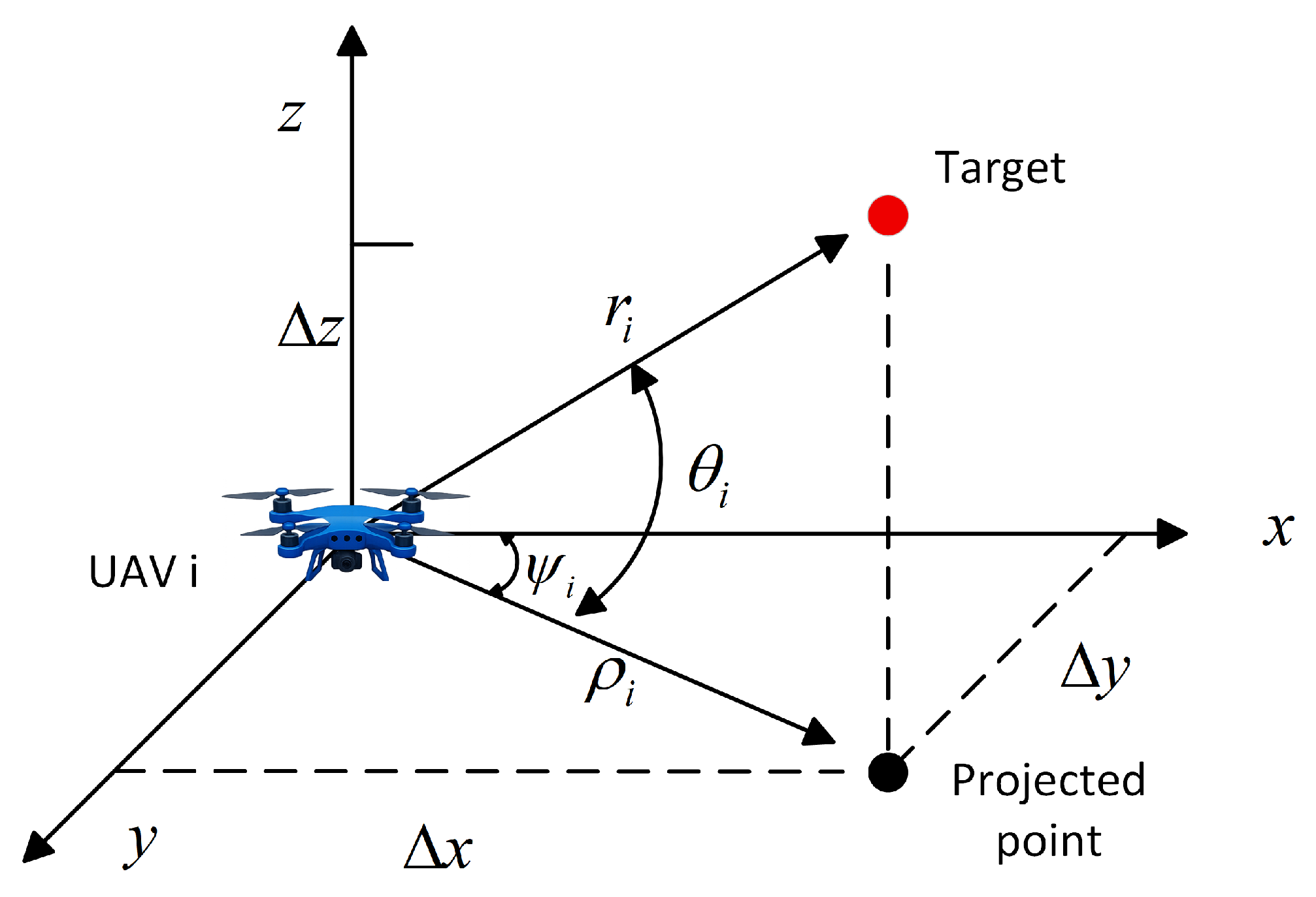
Figure 1 illustrates the AOA measurement geometry. Although the sensor output can be expressed by azimuth and elevation angles, the subsequent bearing-geometry analysis is written in terms of the associated target-centered unit bearing direction n i .
Write the relative position in radial-bearing form as p r , i = r i n i , where r i = p r , i and n i S 2 . Let P τ , i = I 3 n i n i . Differentiating n i = p r , i / r i gives
n ˙ i = d d t p r , i r i = 1 r i I 3 n i n i v r , i .
This relation exposes a structural mismatch between Euclidean motion and direction-space geometry. Even after the radial component is removed by P τ , i , the bearing-direction rate is still scaled by 1 / r i . Hence, the same tangent-projected relative velocity induces different direction-space rates at different radii.
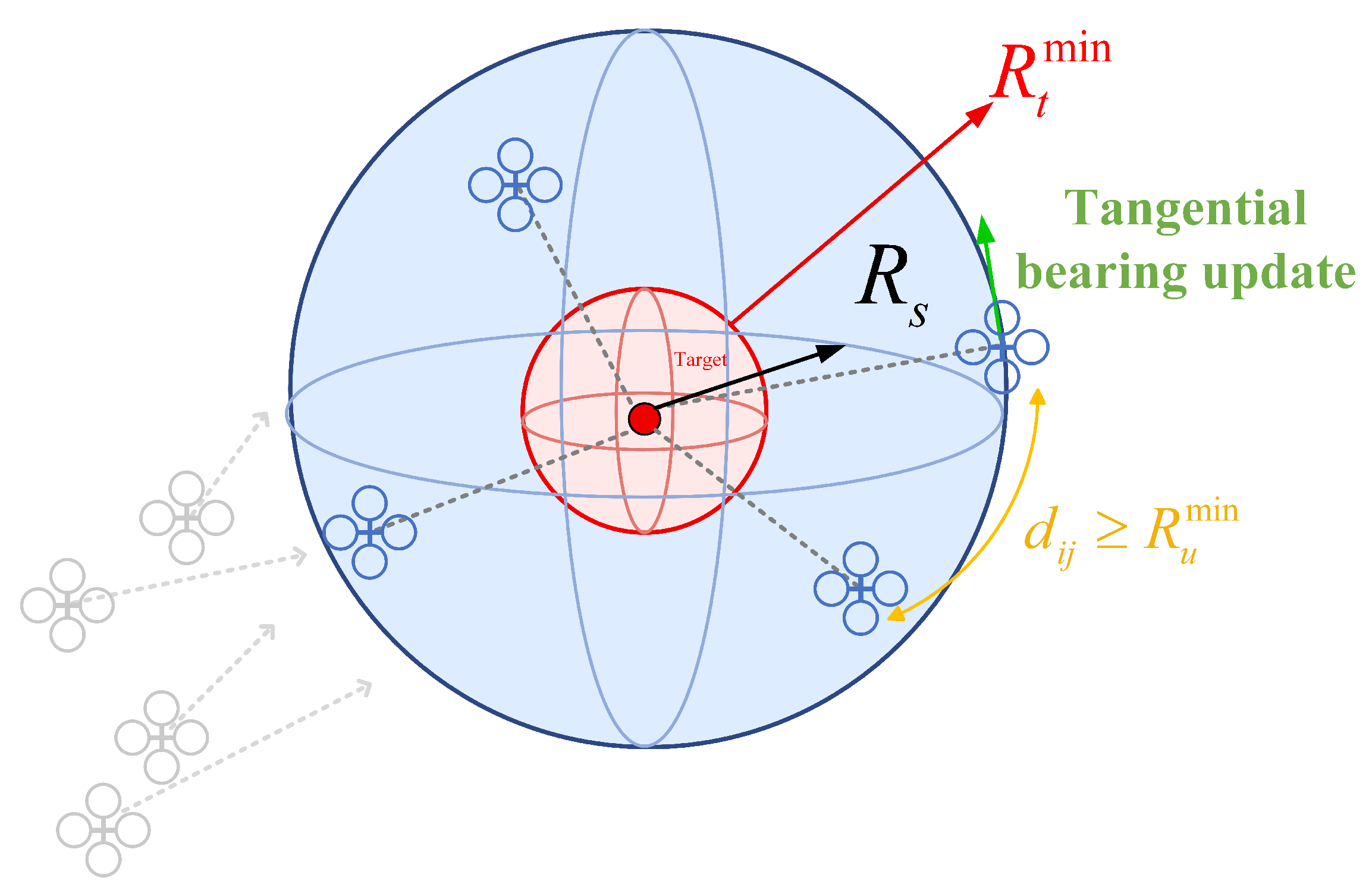
The radial distance cannot be optimized freely. Although reducing r i may increase local AOA information, it may also violate the target-standoff requirement and reduce the feasibility margin for cooperative motion. Hence, an admissible sensing radius R s is chosen with R s > R t min , and the nominal radial objective is r i ( t ) R s . The hard safety constraints are
r i ( t ) R t min , p i ( t ) p j ( t ) R u min , i < j ,
where R t min > 0 and R u min > 0 denote the minimum target-standoff and inter-UAV separation distances, respectively.
The target-standoff constraint is evaluated using the reconstructed target-relative state, whereas the inter-UAV separation constraint is evaluated using UAV–UAV relative states computed from the communicated UAV states. Therefore, the pairwise safety constraint does not require target range sensing; it relies on the available self-localization and inter-UAV communication described above.
The target-centered representation separates the sensing-scale problem from the bearing-geometry problem. The radial variable r i determines whether UAV i lies on the prescribed sensing shell, whereas the unit direction n i determines how the simultaneous bearings span the three-dimensional observation space. Figure 2 illustrates this geometry.
The control objective is to generate the executed input U s = col ( u s , 1 , , u s , N ) such that the radial scale reaches the admissible sensing radius, the bearing directions improve their target-centered angular geometry, and the hard constraints are satisfied. This objective is compactly written as
r i ( t ) R s , V b ( t ) decreases , h t , i ( t ) 0 , h u , i j ( t ) 0 , u s , i ( t ) U i .
where V b = E enc is the bearing-geometry function defined in Section 3.1. The function V b is defined on the unit bearing directions and therefore evaluates the tangential angular geometry after the radial sensing scale has been assigned.
Thus, the problem is not to impose a preassigned circular or helical trajectory, but to coordinate radial sensing-scale regulation, angular bearing-geometry improvement, and safety-critical execution in a target-centered bearing-only setting. The radial channel prevents the information-seeking motion from becoming a range-reduction objective, whereas the tangential channel organizes the simultaneous bearing directions on the assigned sensing scale.
The formulation above exposes three coupled difficulties. First, the angular bearing geometry must be evaluated independently of radial range reduction, while remaining consistent with bearing-only information geometry. Second, the direction-space improvement induced by such a function must be realized through Euclidean UAV motion, despite the 1 / r i scaling in (4). Third, the resulting motion must remain compatible with target-standoff, inter-UAV separation, and input constraints. These difficulties motivate the prescribed-shell bearing-geometry controller developed in Section 3 and the PT-BG-ECBF-QP safety execution layer developed in Section 4.

3. Bearing-Geometry Control

The prescribed-shell bearing-geometry controller is designed to convert the target-centered problem formulation into a nominal radial–tangential command. The shell-compatible bearing-enclosure potential first defines the angular geometry to be improved on the assigned sensing shell. The radial channel then regulates the UAV–target sensing scale, while the tangential channel realizes the bearing-geometry descent through radius-normalized lifting. The resulting nominal command is passed to the safety-critical execution layer in Section 4.
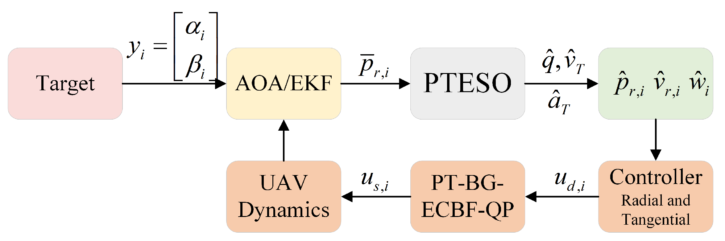
Figure 3 summarizes the implementation flow. Since bearing-only estimation is not the main focus of this paper, the upstream AOA/EKF or AOA/PLKF is treated as a sensing interface that provides a position-type signal p ¯ r , i . A PTESO is then used to reconstruct the variables required by the controller: p ^ r , i , v ^ r , i , and w ^ i . Here, w ^ i is an estimate of the lumped unknown term in (2), rather than a known target-acceleration model. Hereafter, U d = col ( u d , 1 , , u d , N ) denotes the nominal desired command, and U s = col ( u s , 1 , , u s , N ) denotes the safe executed command.
For the relative dynamics in (2), let z 1 , i , z 2 , i , z 3 , i estimate p r , i , v r , i , w i , respectively. With u a , i = u s , i denoting the actually applied acceleration after the safety layer, a compact PTESO interface is
z ˙ 1 , i = z 2 , i l 1 ( t ) φ 1 ( z 1 , i p ¯ r , i ) , z ˙ 2 , i = u a , i z 3 , i l 2 ( t ) φ 2 ( z 1 , i p ¯ r , i ) , z ˙ 3 , i = l 3 ( t ) φ 3 ( z 1 , i p ¯ r , i ) ,
where l j ( t ) > 0 are predefined-time observer gains and φ j ( · ) are nonlinear correction maps. The third observer state z 3 , i is used to estimate the lumped unknown term w i ; therefore, the PTESO does not require an explicit model of the target maneuvering acceleration. The controller uses
p ^ r , i = z 1 , i , v ^ r , i = z 2 , i , w ^ i = z 3 , i ,
and constructs
r ^ i = p ^ r , i , n ^ i = p ^ r , i r ^ i , P ^ τ , i = I 3 n ^ i n ^ i .
The nominal controller is written below in terms of p r , i , v r , i , w i for notational clarity; the implemented form is obtained by replacing them with p ^ r , i , v ^ r , i , w ^ i . To expose the control-layer mechanism, the nominal analysis first considers the reconstruction condition
col ( p ^ r , i p r , i , v ^ r , i v r , i , w ^ i w i ) = 0 , t T o .
For the noisy bearing-only implementation, the reconstruction residual is treated as a bounded perturbation after the observer transient, i.e.,
p ^ r , i p r , i + v ^ r , i v r , i + w ^ i w i δ ¯ o , t T o ,
where δ ¯ o 0 denotes a reconstruction-error bound. The nominal condition in (10) is used to derive the main closed-loop properties of the control layer, whereas (11) explains the practical noisy AOA/EKF–PTESO implementation as a perturbed case.

3.1. Shell-Compatible Bearing-Enclosure Potential

For bearing-only sensing, the information carried by a measurement is determined by both the observation range and the bearing direction. Classical FIM/CRLB-type criteria capture this coupling and are widely used to evaluate localization accuracy. For AOA sensing, a typical information matrix contains a range-dependent scale and an angular sensitivity term associated with the target-centered direction n i . Such criteria are meaningful for estimation-performance evaluation, but they are not directly aligned with the geometry-regulation problem in multi-UAV active tracking. Range reduction and angular redistribution improve bearing information through different mechanisms: the former is limited by target-standoff safety, whereas the latter depends on how the simultaneous bearing directions are distributed after the radial sensing scale has been assigned.
Hence, the angular part of the bearing geometry should be characterized separately from the range-dependent attenuation. The target-centered bearing set { n i } i = 1 N S 2 should not merely be well conditioned in a second-order spectral sense. A finite multi-UAV bearing-only tracker also requires the directed bearing vectors to avoid one-sided collapse and to form a noncoplanar three-dimensional enclosure. This motivates a bearing-geometry function that combines directed balance, second-order angular isotropy, and finite-agent noncoplanar spread.
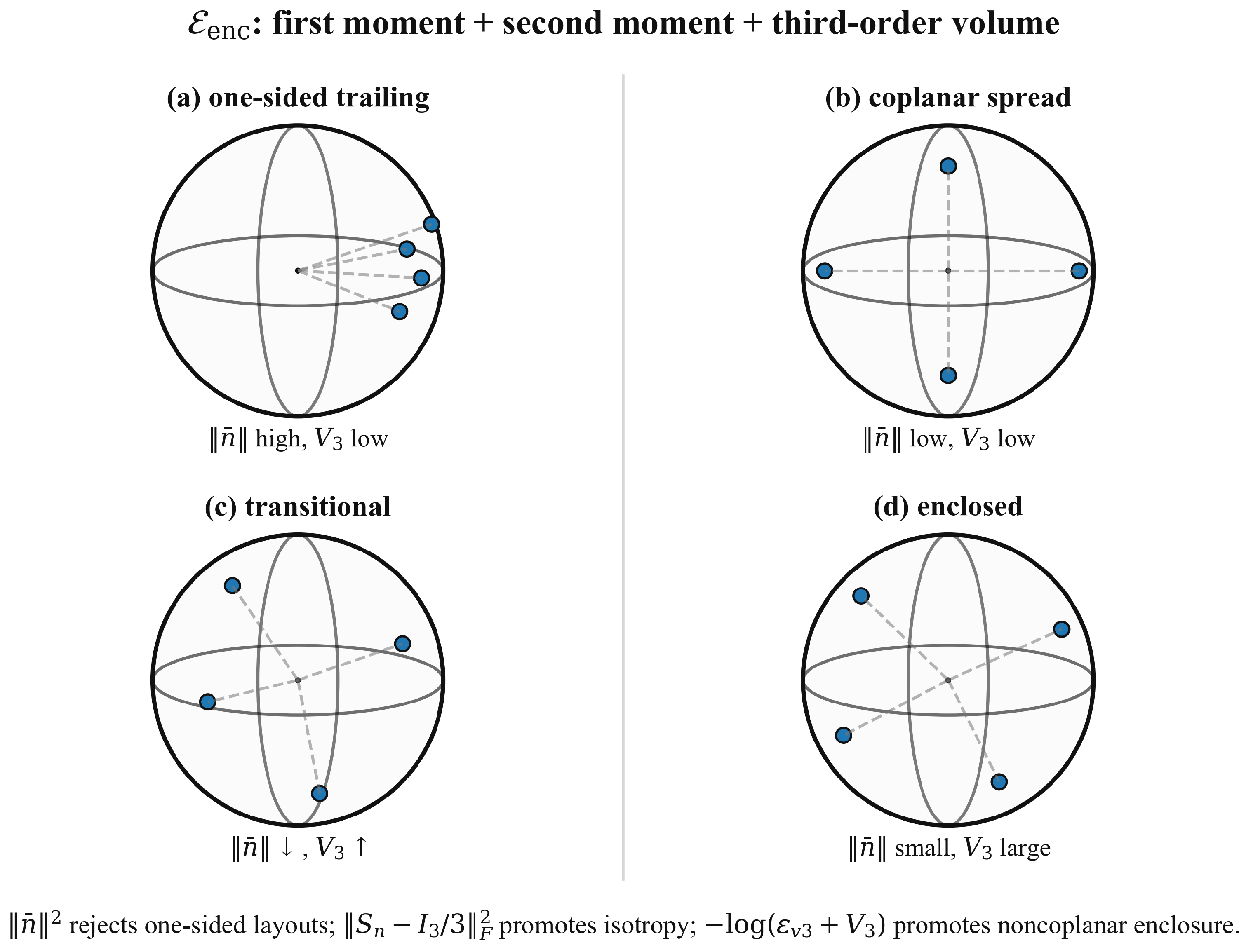
Figure 4 illustrates this requirement on the unit sphere. The first moment n ¯ penalizes one-sided trailing configurations, the second moment S n promotes angular isotropy, and the triple-product volume V 3 penalizes nearly coplanar finite-agent layouts. These three effects are combined in the bearing-enclosure potential E enc .
Let n i S 2 denote the target-centered bearing direction of UAV i. Define the first and second spherical moments
n ¯ = 1 N i = 1 N n i , S n = 1 N i = 1 N n i n i .
The first moment n ¯ measures the directed bias of the bearing distribution. If the bearing vectors are concentrated on one side of the target, n ¯ remains large; if the distribution is directionally balanced around the target, n ¯ tends to zero. The second moment S n describes the second-order angular spread. Since tr ( S n ) = 1 , the isotropic condition S n = I 3 / 3 corresponds to balanced angular excitation in three spatial directions.
It should be noted that n ¯ and S n are used here as first–second-order angular balance indicators, rather than as a standalone finite-agent enclosure certificate. In particular, the first-moment term penalizes one-sided directed bias, and the second-moment term promotes FIM-inspired angular isotropy, but these moment terms alone do not explicitly impose a noncoplanar volume barrier for a finite set of UAV bearings. The noncoplanar finite-agent degeneration is therefore handled by the triple-product volume term introduced below.
The first–second spherical moment discrepancy is defined as
D 2 = w 1 n ¯ 2 + w 2 S n 1 3 I 3 F 2 , w 1 , w 2 > 0 .
The first term penalizes one-sided bearing bias, while the second term penalizes deviation from isotropic angular excitation. This construction is consistent with fixed-radius bearing-information geometry: after the radial scale is fixed, the angular information has the same structural dependence on the unit bearings as i ( I 3 n i n i ) = N ( I 3 S n ) .
The moment discrepancy alone does not explicitly exclude finite-agent coplanar degeneration. To introduce an explicit noncoplanarity measure, assume N 3 so that at least one bearing triplet can be formed. In the three-dimensional enclosure scenarios considered in this paper, N 4 is used so that the UAV team can form a target-centered spatial distribution with both angular spread and front–back enclosure possibility. The averaged triple-product volume is defined as
V 3 = 1 N 3 1 i < j < k N n i n j × n k 2 .
The scalar triple product n i ( n j × n k ) measures the oriented volume spanned by three unit bearing directions. The square in (14) removes the sign ambiguity associated with the ordering of the triplet; hence V 3 0 . Moreover, V 3 = 0 if and only if all scalar triple products vanish, which means that every bearing triplet is linearly dependent, and the bearing set spans a subspace of dimension at most two. Thus, a vanishing V 3 corresponds to a coplanar or lower-dimensional target-centered bearing degeneration, whereas a positive V 3 indicates the existence of noncoplanar bearing triplets. The quantity is computed only from unit bearing directions and therefore does not introduce a radial range-increasing objective.
The shell-compatible moment–volume bearing-enclosure potential is defined as
E enc = D 2 w 3 log ε 3 + V 3 , w 3 > 0 , ε 3 > 0 .
The first part, D 2 , penalizes first–second moment discrepancy of the directed bearing distribution. The logarithmic term acts as an explicit barrier against vanishing noncoplanar volume: it provides a strong descent direction when the finite bearing set approaches a coplanar or lower-dimensional degeneration, and becomes mild after a nondegenerate three-dimensional spread has been established. The small constant ε 3 is a numerical regularization that avoids singular evaluation near V 3 = 0 . The intended ideal domain of the unregularized barrier is V 3 > 0 ; the regularized implementation with ε 3 > 0 is used to maintain numerical well-posedness while still penalizing small noncoplanar volume.
The Euclidean gradient used in the projected descent can be computed explicitly. For the moment discrepancy,
n i D 2 = 2 w 1 N n ¯ + 4 w 2 N S n 1 3 I 3 n i .
Let
Δ i j k = n i ( n j × n k ) , i < j < k .
For a triplet ( i , j , k ) , the derivatives of Δ i j k are
n i Δ i j k = n j × n k , n j Δ i j k = n k × n i , n k Δ i j k = n i × n j .
Thus, n i V 3 is obtained by summing the corresponding contributions over all triplets that contain i. The gradient of E enc is
n i E enc = n i D 2 w 3 ε 3 + V 3 n i V 3 .
Since each n i evolves on S 2 , an admissible change of the bearing direction must lie in the tangent space at n i . Let
g i = P τ , i n i E enc , P τ , i = I 3 n i n i .
The projected descent field associated with E enc is
n ˙ i d = k b g i = k b P τ , i n i E enc , k b > 0 .
Under this ideal direction-space dynamics, and using P τ , i = P τ , i = P τ , i 2 , one obtains
E ˙ enc = i = 1 N ( n i E enc ) n ˙ i d = k b i = 1 N ( n i E enc ) P τ , i n i E enc = k b i = 1 N P τ , i n i E enc 2 0 .
Thus, E enc is monotonically nonincreasing along the ideal direction-space flow, and the stationary set is characterized by
P τ , i n i E enc = 0 , i = 1 , , N .
The descent field in (19) is defined on ( S 2 ) N , whereas the UAVs are driven by Euclidean relative motion. According to (4), even a tangent-projected relative velocity induces a bearing-direction rate scaled by 1 / r i . Thus, the bearing-geometry objective and the physical motion remain connected through a radius-dependent map.
The potential V b = E enc therefore provides the direction-space descent objective, which is realized below through the radial and tangential control channels of the target-centered relative dynamics.

3.2. Radial Shell Regulation

The radial channel is responsible for regulating the sensing scale while leaving the angular bearing distribution to the tangential channel. Let
e r , i = r i R s , e ˙ r , i = n i v r , i .
Define the radial sliding variable
s r , i = e ˙ r , i + k r 1 sig μ e ( e r , i ) + k r 2 sig ν e ( e r , i ) ,
where sig a ( x ) = | x | a sgn ( x ) , k r 1 , k r 2 > 0 , 0 < μ e < 1 , and ν e > 1 . For compactness, define
ϕ r , i = k r 1 sig μ e ( e r , i ) + k r 2 sig ν e ( e r , i ) ,
so that s r , i = e ˙ r , i + ϕ r , i . In numerical implementation, ϕ ˙ r , i is evaluated using a regularized sign-power map or bounded numerical differentiation near e r , i = 0 . This implementation detail avoids singular numerical differentiation and does not change the ideal radial closed-loop dynamics analyzed below.
The term k r 1 sig μ e ( e r , i ) accelerates convergence near the shell, while k r 2 sig ν e ( e r , i ) prevents slow convergence when the radial error is large.
From r i = p r , i , one has
r ˙ i = n i v r , i , n ˙ i = 1 r i P τ , i v r , i .
Therefore,
r ¨ i = n ˙ i v r , i + n i v ˙ r , i = 1 r i v r , i P τ , i v r , i + n i ( u i w i ) .
The nominal radial acceleration command is chosen as
a r , i = 1 r i v r , i P τ , i v r , i ϕ ˙ r , i k s 1 sig α r ( s r , i ) k s 2 sig β r ( s r , i ) ,
where k s 1 , k s 2 > 0 , 0 < α r < 1 , and β r > 1 . The radial component of the nominal input is
u r , i = u p , i + n i n i w ^ i , u p , i = n i a r , i .
The compensation term n i n i w ^ i is used to compensate the radial component of the lumped unknown term; under the nominal reconstruction condition, it cancels the corresponding radial disturbance component. Since
s ˙ r , i = r ¨ i + ϕ ˙ r , i ,
substituting (23) and (25) gives
s ˙ r , i = n i u p , i + 1 r i v r , i P τ , i v r , i n i w i + n i w ^ i + ϕ ˙ r , i = k s 1 sig α r ( s r , i ) k s 2 sig β r ( s r , i ) + n i ( w ^ i w i ) .
Under the nominal reconstruction condition, n i ( w ^ i w i ) = 0 , and (26) provides a finite-time radial reaching tendency for s r , i . Under bounded reconstruction error, the last term in (26) acts as a bounded perturbation and leads to practical shell boundedness unless additional robust margins are introduced. The predefined-time radial shell-reaching requirement is not assigned by (26) alone; it is imposed at the execution layer through the shell-CLF constraint in (35). Specifically, for a prescribed radial shell-reaching horizon T r > 0 , the shell-CLF gains c r 1 , c r 2 , μ r , and ν r are selected to satisfy
1 c r 1 ( 1 μ r ) + 1 c r 2 ( ν r 1 ) T r .
Thus, the nominal radial controller provides the shell-reaching direction, while the PT-BG-ECBF-QP enforces the predefined-time radial shell-reaching inequality whenever the hard shell-CLF constraint is feasible.

3.3. Radius-Normalized Tangential Lifting

The angular geometry objective acts on the bearing directions { n i } i = 1 N , whereas the physical actuator changes p r , i and v r , i . The direction-space descent generated by E enc is
n ˙ i d = k b P τ , i n i E enc .
A direct tangent-projected velocity does not reproduce the desired direction-space descent. Indeed, if
v τ , i 0 = k b P τ , i n i E enc ,
then (4) gives
n ˙ i = 1 r i P τ , i v τ , i 0 = k b r i P τ , i n i E enc .
Thus, without radius normalization, the same tangent-projected Euclidean velocity induces a range-dependent descent rate on S 2 .
To remove this radius-dependent bias, the desired tangential relative velocity is chosen as
v τ , i d = k b r i P τ , i n i E enc .
If the tangential relative velocity satisfies P τ , i v r , i = v τ , i d , then, using P τ , i 2 = P τ , i ,
n ˙ i = 1 r i P τ , i v τ , i d = k b P τ , i 2 n i E enc = k b P τ , i n i E enc .
Hence, the factor r i in (28) compensates the kinematic scaling from Euclidean tangential motion to bearing-direction motion, rather than acting as a heuristic gain amplification.
For the second-order relative dynamics, define the tangential velocity tracking error
e τ , i = P τ , i v r , i v τ , i d .
A nominal tangential acceleration realizing (28) is selected as
u , i = v ˙ τ , i d k v e τ , i , k v > 0 ,
where v ˙ τ , i d is the feedforward derivative of the lifted tangential velocity. In implementation, this term can be evaluated from the estimated variables or approximated with a bounded numerical differentiation error.
The induced tangential tracking dynamics can be written as
e ˙ τ , i = k v e τ , i + d τ , i ,
where d τ , i collects the projection-variation term, feedforward approximation error, estimation residual, and the subsequent QP correction. This residual will appear as a perturbation in the bearing-geometry descent analysis.
The tangential component of the maneuver estimate is compensated by
u τ , i = u , i + P τ , i w ^ i .
Combining the radial and tangential channels gives the nominal command
u d , i = u r , i + u τ , i = u p , i + u , i + w ^ i .
The stacked nominal command is
U d = col ( u d , 1 , , u d , N ) .
This nominal command contains the shell-reaching component, the radius-normalized bearing-geometry component, and the maneuver compensation. It does not yet account for target-standoff, inter-UAV separation, or input constraints; these constraints are imposed by the safety-critical execution layer.

4. PT-BG-ECBF-QP Safety Execution

The nominal command U d generated by the radial–tangential controller improves the sensing scale and the bearing geometry, but it is not guaranteed to satisfy target-standoff, inter-UAV separation, and input constraints. A direct safety filter based only on U U d 2 also does not distinguish between radial shell regulation and tangential bearing-geometry improvement. The execution layer is therefore designed to preserve the shell-reaching tendency as a hard closed-loop requirement, enforce safety through ECBFs, and allocate the remaining admissible control authority in a geometry-preserving manner.

4.1. Predefined-Time Prescribed-Shell CLF

Let s r , i be the radial shell variable defined in (22), and define V r = 1 2 i = 1 N s r , i 2 . This CLF is used to impose a predefined-time reaching requirement for the prescribed sensing shell, rather than to define the shell itself. For a candidate input U = col ( u 1 , , u N ) , the derivative of V r can be written in the affine form
V ˙ r ( U ) = i = 1 N s r , i n i u i + χ r , i ,
where
χ r , i = n i w i + 1 r i v r , i P τ , i v r , i + ϕ ˙ r , i .
In the implemented QP, w i is replaced by its reconstruction w ^ i , and the corresponding residual is handled through the estimation assumption in the closed-loop analysis.
To keep the safety filter from destroying the radial motion toward the prescribed sensing shell, the QP imposes the hard shell-CLF constraint
V ˙ r ( U ) c r 1 V r μ r c r 2 V r ν r ,
where c r 1 , c r 2 > 0 , 0 < μ r < 1 , and ν r > 1 . If the QP remains feasible under (35), the executed input preserves the predefined-time radial shell-reaching inequality. The corresponding predefined-time comparison bound is
T r 1 c r 1 ( 1 μ r ) + 1 c r 2 ( ν r 1 ) .
Therefore, for a prescribed radial shell-reaching horizon T r > 0 , the gains c r 1 , c r 2 , μ r , and ν r are selected such that
1 c r 1 ( 1 μ r ) + 1 c r 2 ( ν r 1 ) T r .
The predefined-time radial shell-reaching conclusion is conditional on the feasibility of the hard shell-CLF constraint together with the ECBF and input constraints. When strict predefined-time radial shell reaching is incompatible with safety or actuation limits, a relaxed implementation may introduce a nonnegative slack variable in (35); the corresponding conclusion then becomes practical shell boundedness rather than exact predefined-time radial shell reaching.

4.2. Target and Inter-UAV ECBFs

The ECBF constraints are constructed using the state variables available to the safety executor. Specifically, the target-standoff ECBF uses the reconstructed target-relative variables, while the inter-UAV ECBF uses UAV–UAV relative states obtained from self-localization, communication, or relative localization. For notational clarity, the derivation below is written with the nominal variables.
The target-standoff constraint in (5) is encoded by
h t , i = r i 2 ( R t min ) 2 .
Since h t , i has relative degree two with respect to u i , the ECBF condition is
h ¨ t , i + c t 1 h ˙ t , i + c t 0 h t , i 0 , c t 0 , c t 1 > 0 .
Since
h ˙ t , i = 2 p r , i v r , i ,
and
h ¨ t , i = 2 v r , i v r , i + 2 p r , i ( u i w i ) ,
substituting these expressions into (39) yields the affine constraint
2 p r , i u i + b t , i 0 ,
where
b t , i = 2 v r , i v r , i 2 p r , i w i + c t 1 h ˙ t , i + c t 0 h t , i .
In implementation, p r , i , v r , i , and w i in the target-standoff ECBF are replaced by their reconstructed values p ^ r , i , v ^ r , i , and w ^ i , respectively.
For inter-UAV safety, the pairwise ECBF is constructed from the UAV–UAV relative state rather than from the target-bearing measurement. Let p i j = p i p j and v i j = v i v j , and define
h u , i j = p i j 2 ( R u min ) 2 , i < j .
The corresponding ECBF condition is
h ¨ u , i j + c u 1 h ˙ u , i j + c u 0 h u , i j 0 , c u 0 , c u 1 > 0 .
Since
h ˙ u , i j = 2 p i j v i j ,
and
h ¨ u , i j = 2 v i j v i j + 2 p i j ( u i u j ) ,
(42) becomes
2 p i j ( u i u j ) + b u , i j 0 ,
where
b u , i j = 2 v i j v i j + c u 1 h ˙ u , i j + c u 0 h u , i j .

4.3. Geometry-Preserving Control Allocation

Safety correction is unavoidable when the nominal command points toward the boundary of the admissible set. The remaining issue is how this correction is allocated. Since the radial component is tied to shell reaching and the tangential component carries the bearing-geometry descent, the QP objective separates the two directions.
Let
P r = blkdiag ( n i n i ) , P τ = blkdiag ( P τ , i ) .
The geometry-dependent tangential weight is selected as
W τ = W τ 0 + c w ρ g I ,
where W τ 0 0 , c w 0 , and
ρ g = D 2 + w 3 ε 3 + V 3 .
The scalar ρ g is used only as a nonnegative allocation weight, not as the descent potential itself. It increases when the first–second moment discrepancy is large or when the triple-product volume approaches degeneration. Hence, when the bearing geometry is poorly conditioned in the moment–volume sense, the QP penalizes unnecessary tangential deviation from the enclosure-improving nominal command.
For close UAV pairs, a small tangential separation bias is added to shape the admissible safety correction without introducing a new hard constraint. The purpose is not to replace the ECBF pairwise safety condition, but to favor shell-tangential corrections that relieve local crowding while minimally disrupting the bearing-geometry descent. Define
A c = { ( i , j )   p i p j d c , i < j } ,
and
d i j τ , i = P τ , i ( n i n j ) , d i j τ , j = P τ , j ( n j n i ) .
The allocation cost is
J q ( U ) = P r ( U U d ) W r 2 + P τ ( U U d ) W τ 2 α c ( i , j ) A c ( d i j τ , i ) u i + ( d i j τ , j ) u j ,
where W r 0 and α c 0 . The last term is linear in U; it reshapes the safety correction direction but does not replace the ECBF constraints responsible for hard safety.

4.4. Complete PT-BG-ECBF-QP

Using the reconstructed target-relative variables and the available UAV–UAV relative states described above, the executed command is obtained from the convex QP
U s = arg min U J q ( U ) s . t . V ˙ r ( U ) c r 1 V r μ r c r 2 V r ν r , 2 p r , i u i + b t , i 0 , i = 1 , , N , 2 p i j ( u i u j ) + b u , i j 0 , i < j , u i U i , i = 1 , , N .
The first constraint preserves the predefined-time radial shell-reaching inequality whenever it is compatible with the ECBF and input constraints. The second and third constraints enforce target-standoff and inter-UAV safety, and the last constraint enforces actuation limits. The objective (45) keeps the safe input close to U d while weighting radial and tangential deviations according to their different roles in the bearing-only tracking problem.
The QP is convex. Indeed, W r 0 and W τ 0 , while the close-pair term in (45) is linear in U. Hence, the Hessian of the objective is positive semidefinite. Since the shell-CLF, ECBF, and input constraints are affine in U, (46) is a convex QP. If a unique optimizer is required in implementation, a small regularization term ε q U U d 2 with ε q > 0 can be added without changing the constraint set.

5. Closed-Loop Analysis

This section establishes the closed-loop properties induced by the hard shell-CLF constraint, the bearing-geometry descent, and the ECBF safety inequalities. The analysis is carried out for the control layer after the observer transient, with the nominal reconstruction case used to derive the main results and bounded reconstruction errors treated as practical perturbations.
Assumption 1 (Nominal and bounded PTESO reconstruction).
The upstream bearing-only reconstruction filter is treated as an estimation interface rather than as an additional closed-loop state in the control-layer analysis. For the nominal analysis, the reconstruction error satisfies
col ( p ^ r , i p r , i , v ^ r , i v r , i , w ^ i w i ) = 0 , t T o , i = 1 , , N .
In the noisy bearing-only implementation, the reconstruction error is allowed to be bounded after the observer transient, i.e.,
p ^ r , i p r , i + v ^ r , i v r , i + w ^ i w i δ ¯ o , t T o .
The main theorems below are stated for the nominal reconstruction case, while bounded reconstruction residuals are interpreted as perturbations that lead to practical boundedness or require robust QP margins.
Assumption 2 (QP feasibility and ECBF-admissible initialization).
For all t T o , the hard-constraint QP (46), constructed from the reconstructed target-relative variables and the available UAV–UAV relative states, admits at least one solution satisfying the shell-CLF, ECBF, and input constraints. Moreover, at the beginning of the safety-executed interval, each ECBF constraint is admissible, i.e.,
h ( T o ) 0 , ψ ( T o ) = h ˙ ( T o ) + λ 1 h ( T o ) 0 ,
for the corresponding target-standoff or inter-UAV safety function, where λ 1 , λ 2 > 0 , c 1 = λ 1 + λ 2 , and c 0 = λ 1 λ 2 .
Theorem 1 (Predefined-time radial shell reaching).
Suppose Assumptions 1 and 2 hold. If the executed input satisfies the hard shell-CLF constraint (35) and the gains are selected according to (37), then the radial shell variable s r , i reaches zero no later than T r after the observer transient in the nominal reconstruction case. On the manifold s r , i = 0 , the radial error satisfies
e ˙ r , i = k r 1 sig μ e ( e r , i ) k r 2 sig ν e ( e r , i ) ,
and reaches zero within
T e 1 k r 1 ( 1 μ e ) + 1 k r 2 ( ν e 1 ) .
Therefore,
e r , i ( t ) = 0 , t T o + T r + T e , i = 1 , , N .
Proof. 
For t T o , Assumption 1 gives the nominal reconstruction condition used in the control-layer analysis. Since the executed input satisfies the hard shell-CLF constraint (35), one has
V ˙ r c r 1 V r μ r c r 2 V r ν r , c r 1 , c r 2 > 0 , 0 < μ r < 1 , ν r > 1 .
By the standard predefined-time comparison argument, the set V r = 0 is reached within
T r 1 c r 1 ( 1 μ r ) + 1 c r 2 ( ν r 1 ) .
Using the gain-selection condition (37) gives T r T r . Since V r = 1 2 i = 1 N s r , i 2 , V r = 0 implies s r , i = 0 for all i = 1 , , N . On the manifold s r , i = 0 , the definition of s r , i yields
e ˙ r , i = k r 1 sig μ e ( e r , i ) k r 2 sig ν e ( e r , i ) .
Applying the same comparison argument to this scalar radial-error dynamics gives
T e 1 k r 1 ( 1 μ e ) + 1 k r 2 ( ν e 1 ) .
Therefore, the radial error satisfies e r , i ( t ) = 0 for t T o + T r + T e , i = 1 , , N . □
Remark 1.
The strict reaching result depends on the hard shell-CLF constraint and on the feasibility of (46). If a slack variable is introduced to resolve temporary conflicts among shell reaching, safety, and input limits, the radial conclusion is weakened to practical shell boundedness, with a residual set determined by the slack bound.
Theorem 2 (Bearing-geometry descent).
Let the bearing-geometry function be
V b ( n ) = E enc ( n ) ,
where E enc is defined in (15). Define
g i = P τ , i n i V b , G b = col ( g 1 , , g N ) .
Under the ideal direction-space flow n ˙ i = k b g i , one has
V ˙ b = k b G b 2 0 .
If the safety-executed Euclidean motion induces the perturbed bearing dynamics
n ˙ i = k b g i + d b , i ,
where D b = col ( d b , 1 , , d b , N ) is bounded by D b ( t ) d ¯ b , then
V ˙ b k b 2 G b 2 + d ¯ b 2 2 k b .
Consequently, the projected bearing gradient is ultimately bounded, and the descent is strict whenever G b > d ¯ b / k b .
Proof. 
Since V b = E enc , its derivative along the bearing dynamics is
V ˙ b = i = 1 N ( n i V b ) n ˙ i .
For the ideal direction-space flow,
V ˙ b = k b i = 1 N ( n i V b ) P τ , i n i V b = k b i = 1 N P τ , i n i V b 2 = k b G b 2 0 ,
where P τ , i = P τ , i = P τ , i 2 has been used.
For the safety-executed motion,
n ˙ i = k b g i + d b , i .
The perturbation d b , i collects the tangential velocity tracking residual, QP correction, estimation residual, and implementation errors in the induced bearing dynamics. In particular, the tangential velocity residual contributes through
d b , i v = 1 r i e τ , i ,
up to projection-variation and QP-correction terms. Then
V ˙ b = i = 1 N ( n i V b ) ( k b g i + d b , i ) = k b G b 2 + G b D b .
By Young’s inequality,
G b D b k b 2 G b 2 + 1 2 k b D b 2 .
Using D b d ¯ b gives (47). □
Corollary 1 (Ideal bearing-geometry stationarity).
If D b 0 , then V b = E enc is monotonically nonincreasing, and the ideal direction-space flow can stop only on the stationary set
P τ , i n i V b = 0 , i = 1 , , N .
Theorem 3 (Forward invariance of the safety set).
Suppose Assumption 2 holds. Then the safety set
C = x | h t , i ( x ) 0 , i = 1 , , N , h u , i j ( x ) 0 , i < j
is forward invariant under the executed input U s .
Proof. 
Consider any target-standoff or inter-UAV safety function h ( x ) . The QP imposes the second-order ECBF inequality:
h ¨ + c 1 h ˙ + c 0 h 0 ,
where c 1 = λ 1 + λ 2 , c 0 = λ 1 λ 2 , and λ 1 , λ 2 > 0 . Define the extended safety variable
ψ = h ˙ + λ 1 h .
Then
ψ ˙ + λ 2 ψ = h ¨ + ( λ 1 + λ 2 ) h ˙ + λ 1 λ 2 h 0 .
By Assumption 2, ψ ( T o ) 0 . The comparison lemma gives
ψ ( t ) e λ 2 ( t T o ) ψ ( T o ) 0 , t T o .
Since h ˙ + λ 1 h = ψ ( t ) 0 , another comparison argument yields
h ( t ) e λ 1 ( t T o ) h ( T o ) 0 , t T o .
Therefore, every target-standoff and inter-UAV safety function remains nonnegative, which proves forward invariance of C . □
Theorem 4 (Overall closed-loop boundedness).
Under Assumptions 1 and 2, the safety-executed closed-loop signals in the target-centered control layer are bounded. Moreover, under the hard shell-CLF constraint and QP feasibility, the radial shell error converges to zero, the safety set is forward invariant, and the projected bearing-gradient is ultimately bounded by a neighborhood determined by d ¯ b .
Proof. 
The input constraint in (46) gives bounded executed input U s . Theorem 1 gives bounded radial motion and convergence of r i to R s under the hard shell-CLF constraint and QP feasibility. Theorem 3 implies r i ( t ) R t min and p i ( t ) p j ( t ) R u min for all admissible pairs. Since n i S 2 , the bearing directions remain bounded by construction. Theorem 2 gives practical descent of V b = E enc and ultimate boundedness of G b . Together with Assumption 1, these properties imply boundedness of the considered target-centered closed-loop signals. □

6. Simulation Studies

This section validates the proposed framework from the viewpoints of closed-loop tracking, bearing-enclosure optimization, radius-normalized tangential lifting, and PT-BG-ECBF-QP safety execution. The numerical comparisons focus on the control layer after the target-centered variables are provided by the estimation interface in Section 3; thus, the upstream AOA/EKF or AOA/PLKF filter is not treated as a separate closed-loop state in the ablation studies. A ROS-based simulation is further included to examine whether the complete AOA/EKF–PTESO–control–QP pipeline preserves the prescribed-shell and bearing-information properties in an integrated middleware-level implementation.
The main numerical setup is summarized in Table 2. Unless otherwise specified, all compared methods use the same target motion, initial conditions, sampling period, and input constraints.

6.1. Overall Tracking Performance

The main scenario uses a rear-side layered initialization to avoid a favorable initial enclosure and to force the UAVs to approach the prescribed sensing shell while reorganizing their target-centered bearing directions. All UAVs are initially located behind the target with different radial distances, and all pairwise distances satisfy the safety requirement. The key setup parameters are summarized in Table 2.
The resulting performance statistics are reported in Table 3. The proposed controller reaches enclosure at T enc = 89.04 s , with n ¯ = 1.504 × 10 4 , λ min ( S n ) = 0.3332 , κ ( S n ) = 1.001 , and a final front–back distribution of 2 / 2 .
Here, d min ( 0 ) = min i < j p i ( 0 ) p j ( 0 ) is computed from the selected initial UAV positions and is reported only to characterize the initial inter-UAV safety condition; it is not a controller tuning parameter. The controller-related safety parameter for inter-UAV separation is R u min .
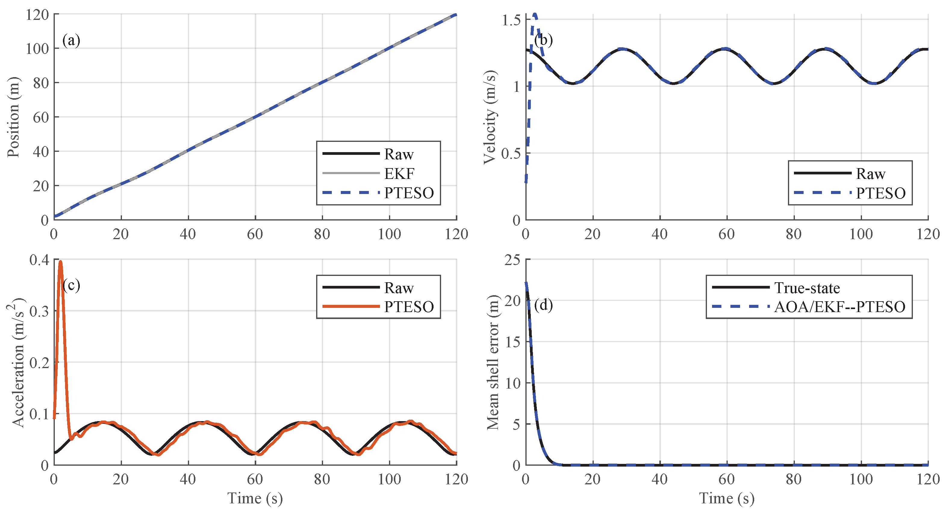
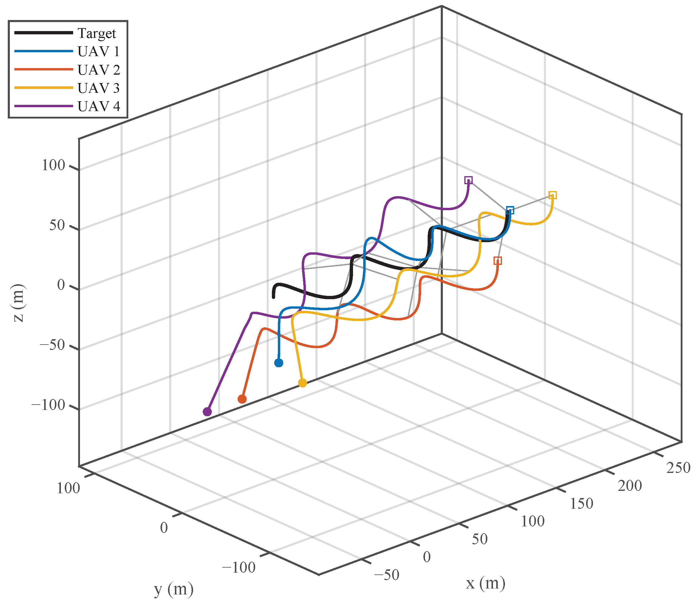
Before evaluating the target-centered motion, Figure 5 checks the sensing–estimation interface used by the controller. The AOA/EKF–PTESO reconstruction provides sufficiently smooth position, velocity, and maneuver estimates, and the resulting shell-tracking error remains close to that of the true-state implementation. This supports the use of the reconstructed target-centered variables in the subsequent control-layer comparisons. Figure 6 shows the three-dimensional tracking process. The UAVs start from a rear-side lower region, approach the moving target, and gradually form a target-centered bearing enclosure. The final geometry is generated by the radial–tangential controller and the safety execution layer, rather than being imposed as a preassigned circular or helical formation.
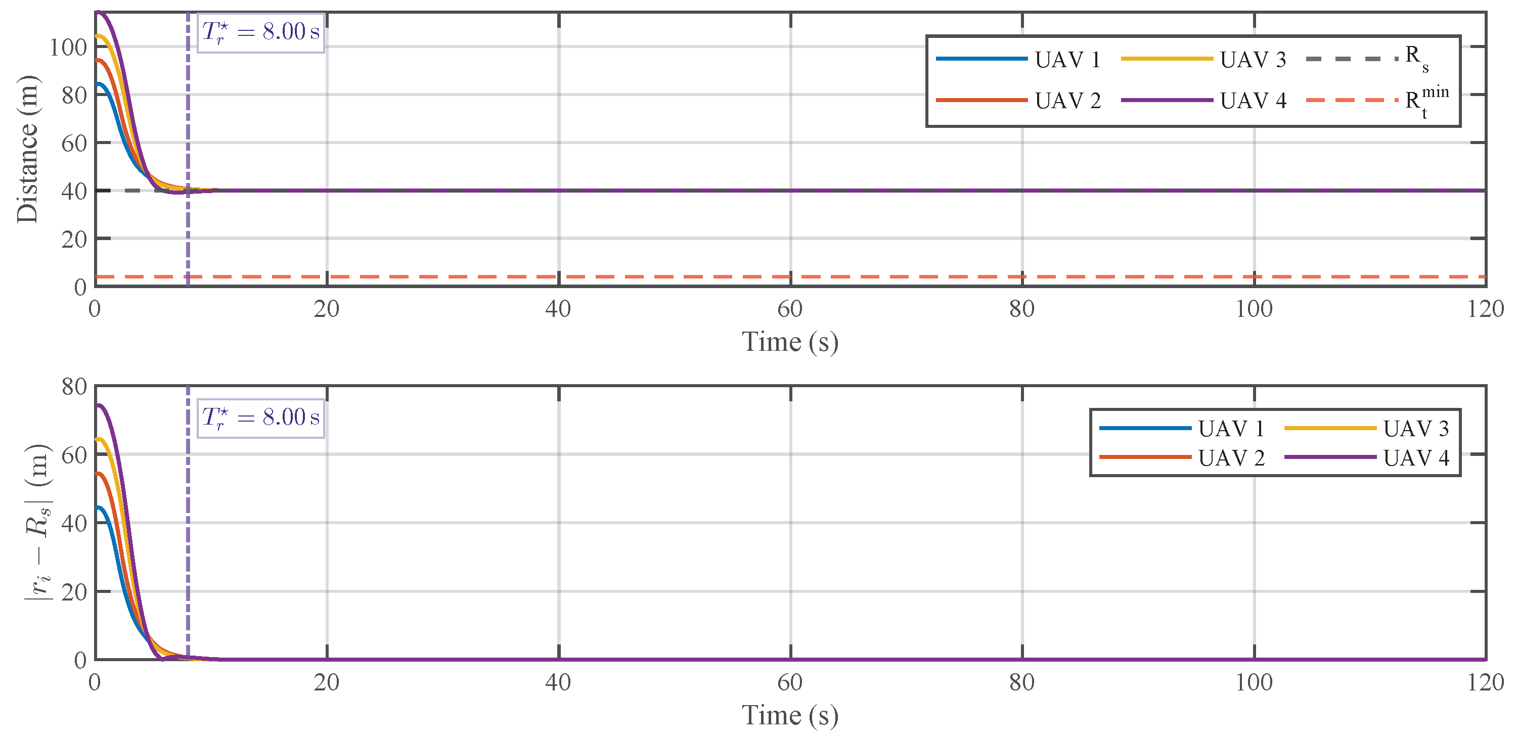
Figure 7 reports the target-centered distances and the corresponding shell errors in the main scenario. The UAVs approach the prescribed radius R s from different initial distances and remain outside the target-standoff boundary R t min . The vertical dashed line denotes the prescribed radial shell-reaching horizon T r = 8.00 s. The shell errors enter a small neighborhood of zero before this design time bound, confirming that the radial channel establishes an admissible sensing scale without relying on unsafe range reduction to improve bearing information.
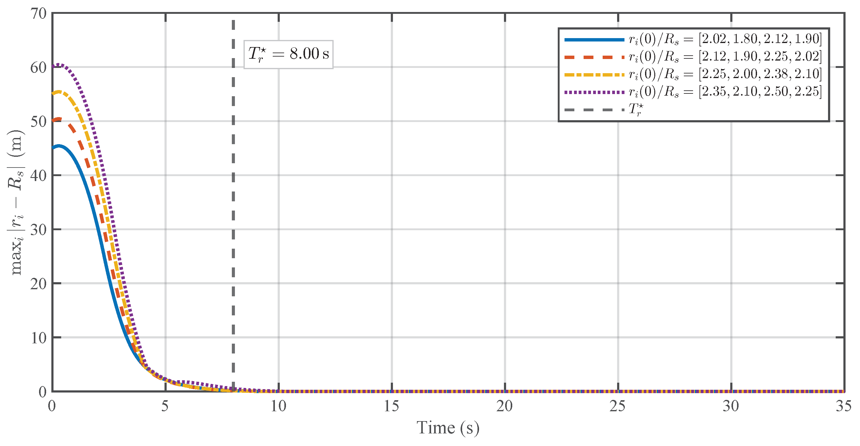
To further examine the predefined-time radial shell-reaching behavior, additional simulations are conducted with different initial UAV position configurations. The controller parameters, prescribed sensing radius, safety distances, QP weights, and input bounds are kept unchanged across all cases. The maximum radial shell error is defined as
e max ( t ) = max i = 1 , , N | r i ( t ) R s | .
As shown in Figure 8, all tested initial configurations enter a small neighborhood of the prescribed sensing shell before the same design horizon T r = 8.00 s. This verifies that the predefined-time term acts on the radial shell-reaching behavior, while the bearing-geometry optimization remains handled by the tangential channel.
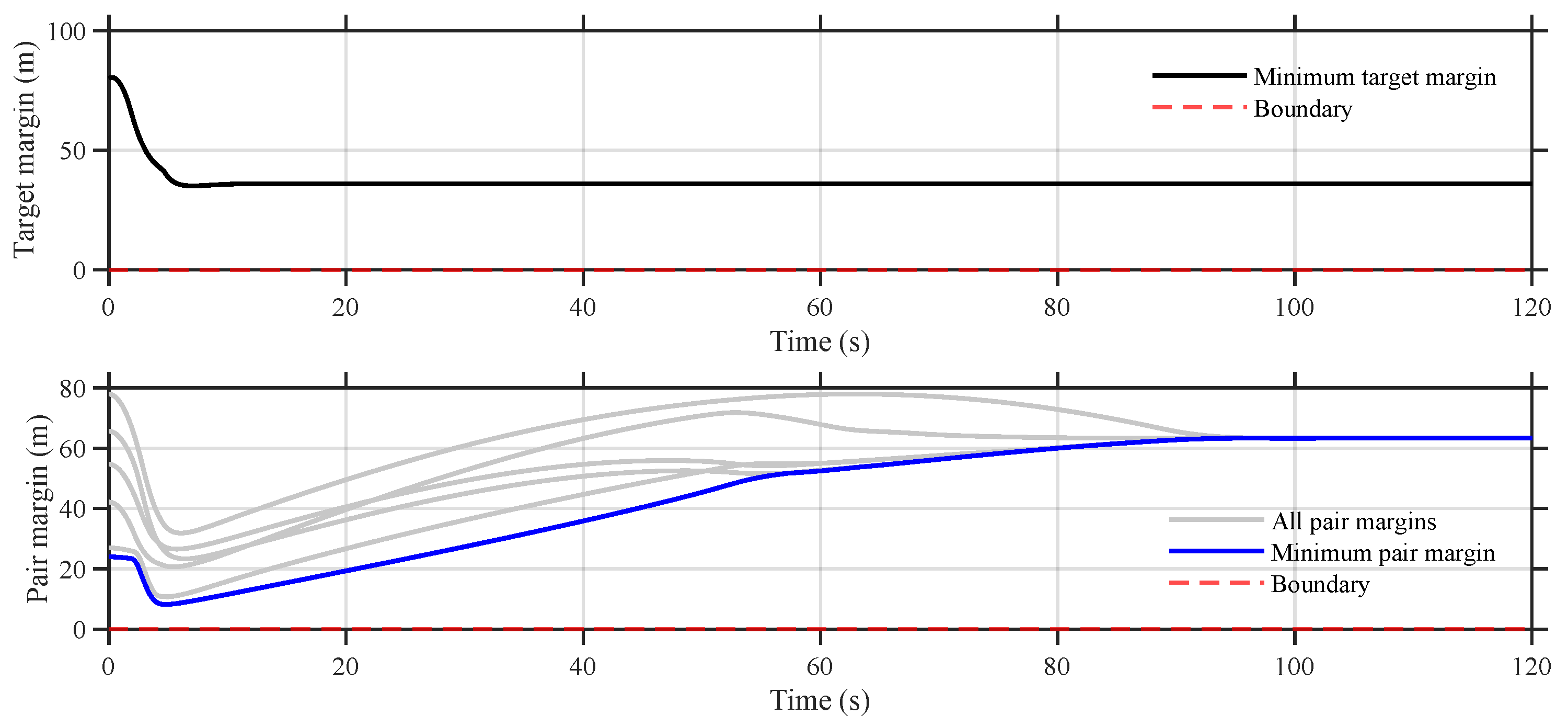
Figure 9 shows the target-standoff and inter-UAV safety margins. Both margins remain positive during the maneuver. The minimum pair margin decreases during the initial reorganization phase but stays above the boundary, which is consistent with the forward invariance enforced by the ECBF constraints.
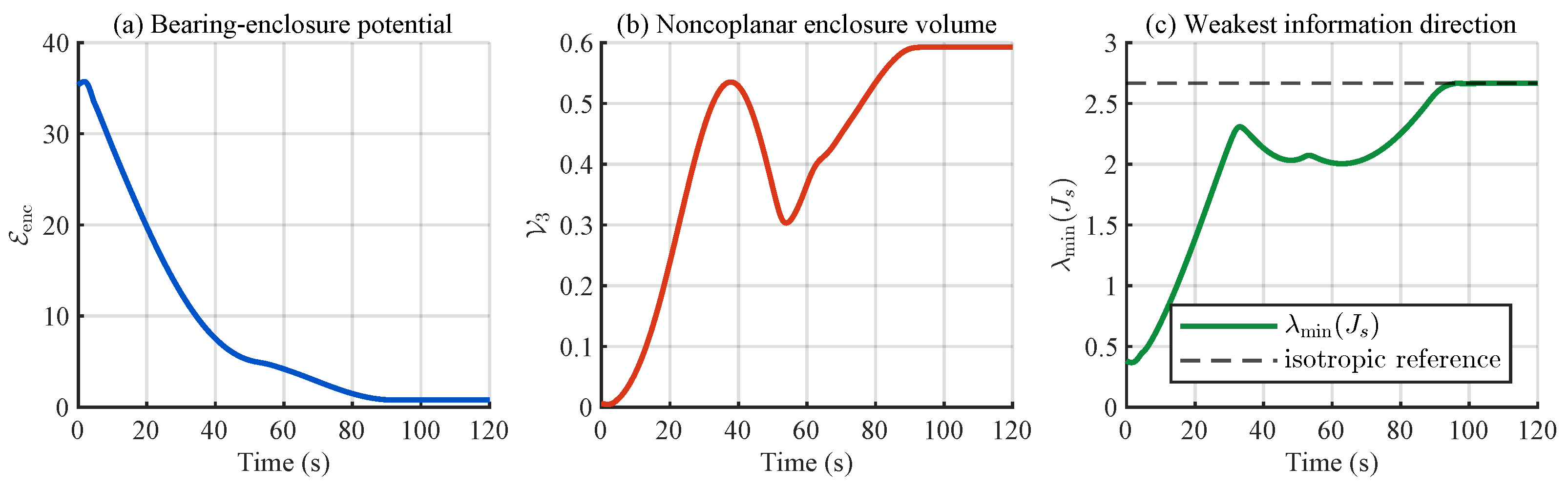
Figure 10 shows the evolution of the bearing-enclosure potential and its main geometric effects. The value of E enc decreases rapidly, while the noncoplanar volume V 3 increases and the weakest information direction λ min ( J s ) moves toward the isotropic reference. This confirms that the moment–volume potential drives the bearing directions away from one-sided or coplanar layouts and toward a more informative shell geometry.

6.2. Effect of the Bearing-Enclosure Potential

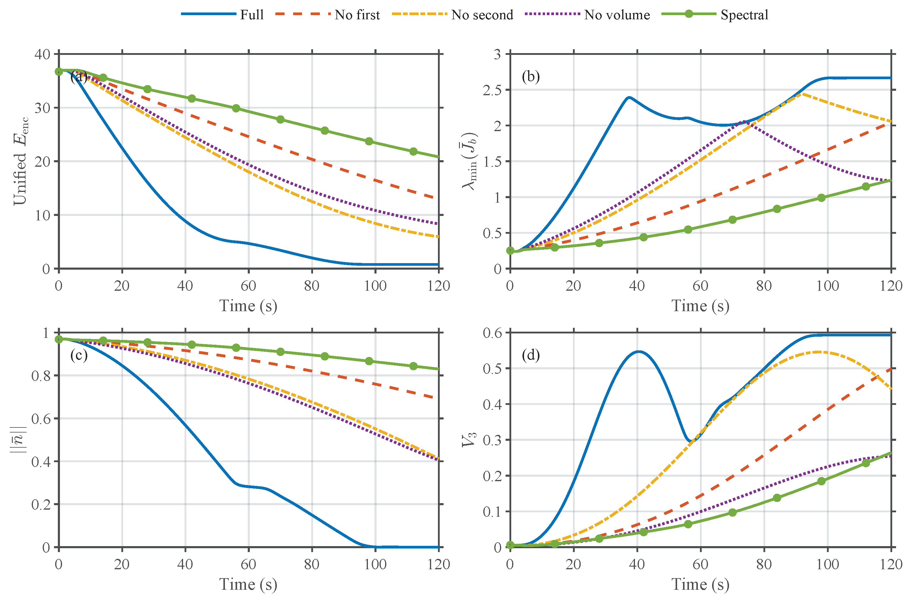
The second study evaluates the proposed bearing-enclosure potential in an independent metric-sensitive case. The purpose is to isolate the effect of the moment–volume construction, rather than to repeat the overall tracking test. The compared variants include the full potential, the no-first-moment variant, the no-second-moment variant, the no-volume variant, and a second-order spectral baseline.
All variants are evaluated using the same full bearing-enclosure potential E enc , the shell-normalized bearing information matrix
J s = i = 1 N ( I 3 n i n i ) = N ( I 3 S n ) ,
and two enclosure-quality quantities, n ¯ and V 3 .
Figure 11 compares the metric variants. The full potential gives the fastest reduction of the unified evaluation potential, improves the weakest bearing-information direction, removes the directed one-sided bias, and increases the noncoplanar enclosure volume.
The no-first-moment and spectral variants, however, retain a large n ¯ , indicating that second-order information improvement alone does not guarantee a directed target-centered enclosure.
The quantitative results in Table 4 support the same conclusion. The full potential reaches enclosure at T enc = 99.14 s , with final c n = 1.555 × 10 4 , V 3 = 0.5926 , and front–back = 2 / 2 . By contrast, the no-first-moment and spectral variants do not reach enclosure within the simulation horizon and remain in a 0 / 4 front–back trailing pattern, with final c n 0.5773 . The no-second and no-volume variants can eventually form an enclosure, but they require a longer time and exhibit weaker balance in the transient geometry. Thus, the full potential is beneficial because it couples directed balance, second-order angular excitation, and finite-agent volume expansion.
To further relate the proposed bearing-enclosure potential to classical information geometry, a static Monte Carlo benchmark is conducted on the prescribed shell. The UAV radii are fixed as r i = R s , and 5 × 10 4 random bearing configurations are sampled on ( S 2 ) N . For each sample, the shell-normalized bearing information matrix
J s = i = 1 N ( I 3 n i n i )
is evaluated together with λ min ( J s ) , tr ( ( J s + ε I 3 ) 1 ) , κ ( J s ) , and det ( J s + ε I 3 ) . The final geometry generated by the proposed closed loop is then compared with the sampled distribution and with the isotropic tetrahedral reference.
For the four-UAV case considered here, the theoretical optimum is the ideal tetrahedral bearing distribution on the prescribed shell, where n ¯ = 0 , S n = I 3 / 3 , and the static bearing information is isotropic. Table 5 shows that the final geometry obtained by the proposed method is almost identical to this optimum. Its FIM/CRLB-related indicators nearly match the theoretical values, while n ¯ approaches zero and V 3 reaches the noncoplanar tetrahedral value. This confirms that minimizing E enc drives the bearing directions toward a near-optimal fixed-radius information geometry, rather than merely producing a feasible shell configuration.

6.3. Effect of Radius-Normalized Tangential Lifting

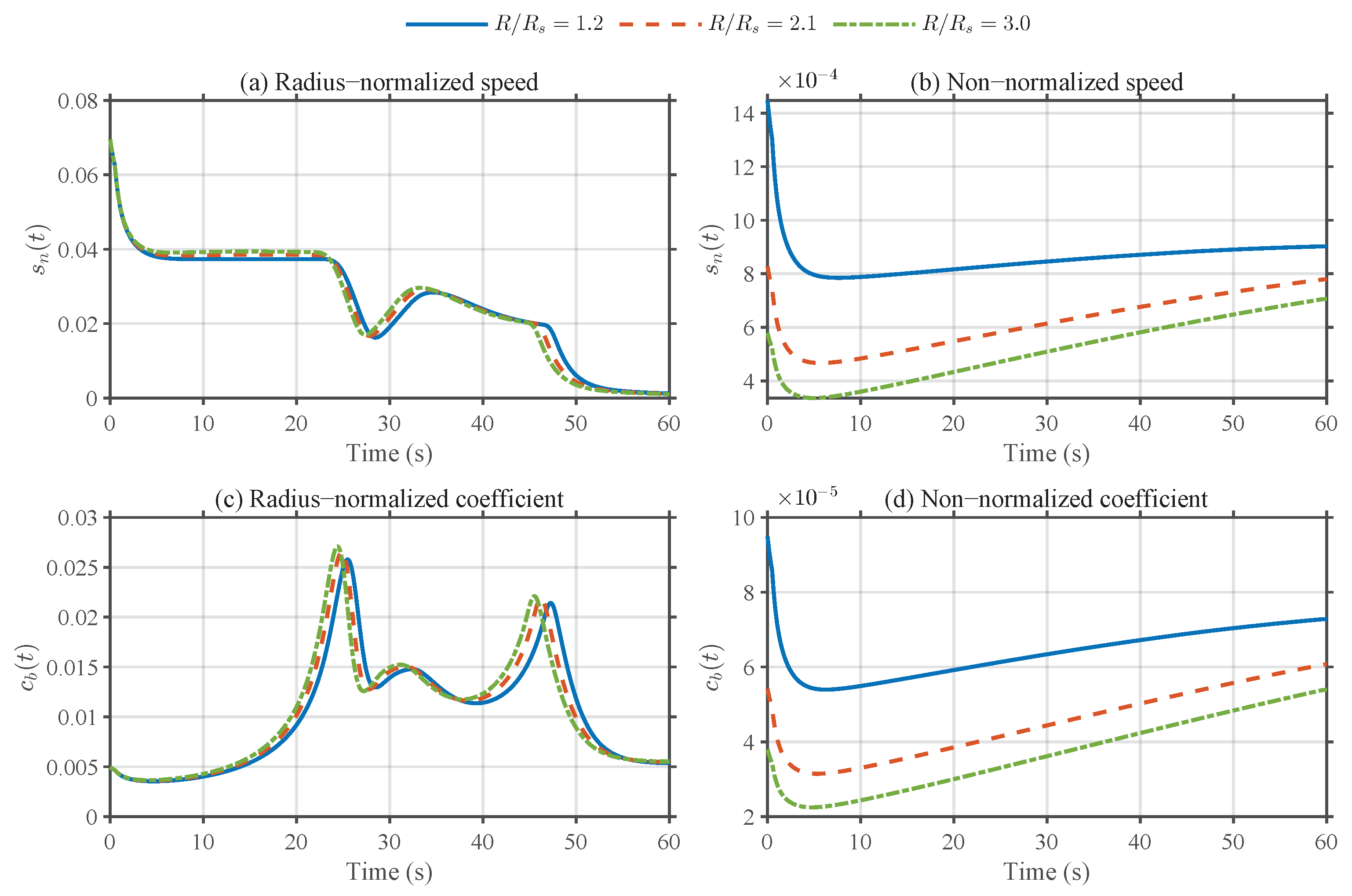
The third study examines the radius-normalized lifting through an isolated radius-invariance experiment. The initial bearing configuration is kept identical, while the radius scale is changed. This directly tests the bearing-direction kinematics
n ˙ i = 1 r i P τ , i v r , i .
If the Euclidean tangential command is not radius-normalized, the induced direction-space descent is attenuated by the factor 1 / r i . If the proposed lifting is used, the induced direction-space flow should be approximately independent of the radius.
Figure 12 reports the direction-space speed
s n ( t ) = 1 N i = 1 N n ˙ i ( t )
and the descent-rate coefficient
c b ( t ) = V ˙ b ( t ) i = 1 N P τ , i n i V b 2 .
For the radius-normalized lifting, the curves corresponding to different radius scales almost overlap. For the non-normalized implementation, they separate clearly, and the induced direction-space speed is attenuated as the radius increases. This verifies that the proposed lifting compensates for the 1 / r i bearing-kinematic map, rather than merely increasing the tangential gain.

6.4. Effect of PT-BG-ECBF-QP Safety Execution

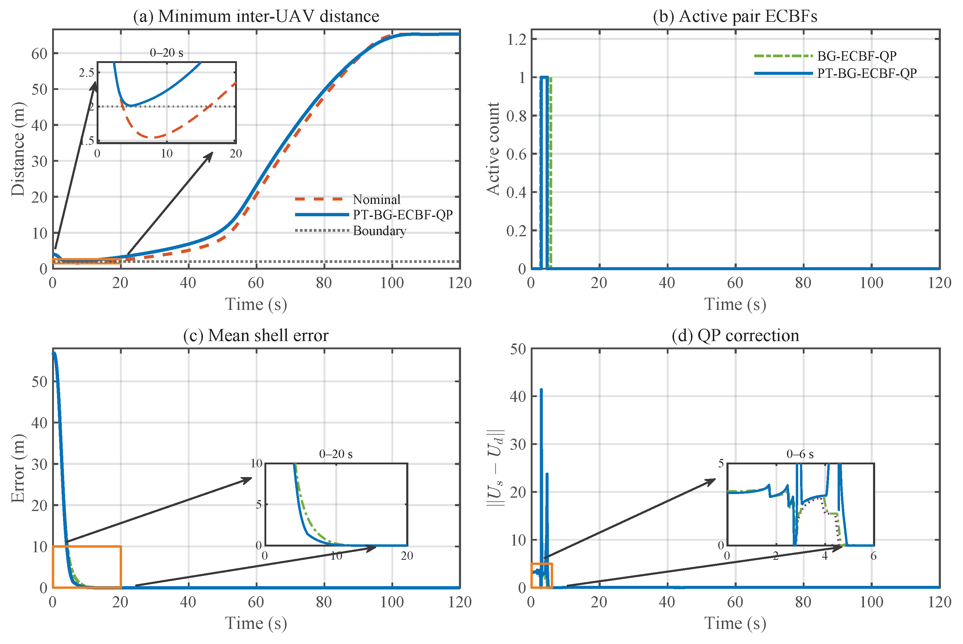
The final study evaluates the safety execution layer under a stress case. Figure 13 first demonstrates why the ECBF-QP layer is necessary. Without the safety filter, the nominal command violates the inter-UAV safety boundary. With the proposed PT-BG-ECBF-QP, the inter-UAV distance remains above R u min . The active-pair indicator and correction norm show that the QP is actually engaged during the stress interval, rather than remaining inactive. The comparison between BG-ECBF-QP and PT-BG-ECBF-QP in the shell-error subplot further shows that embedding the predefined-time radial shell-reaching objective helps preserve the prescribed shell during safety correction.
This experiment is intentionally isolated from the complete tracking scenario: the initial bearing configuration is fixed, and only the radius scale is changed, so that the effect of the 1 / r i map can be observed without being hidden by target motion, radial regulation, or safety corrections.
Table 6 gives the corresponding numerical summary. The nominal controller has a negative minimum pair margin 0.4557 m , confirming that the safety filter is needed. The standard ECBF-QP, BG-ECBF-QP, and PT-BG-ECBF-QP all keep the pair margin nonnegative. In particular, PT-BG-ECBF-QP gives a positive minimum pair margin 0.01313 m and the smallest mean shell error 0.06454 m among the safe variants. Its QP active ratio is 0.9507 , indicating that the execution layer is frequently engaged.
The feasible ratio of the PT-BG-ECBF-QP is 0.9588 . Therefore, the result is interpreted as an executed numerical stress test with positive reported safety margins, rather than as an empirical proof of the all-time solver feasibility. The theoretical safety statement remains conditioned on the hard-QP feasibility assumption in Section 5.
To further isolate the role of the geometry-preserving allocation in the execution layer, a dense ten-UAV shell-crowding case is considered. Both QP variants enforce the same target-standoff, inter-UAV ECBF, shell-CLF, and input constraints; they differ only in whether the BG-preserving allocation term is included in the QP objective. Hence, the comparison is intended to evaluate how unavoidable safety corrections are distributed, rather than whether safety is enforced by one method but not the other.
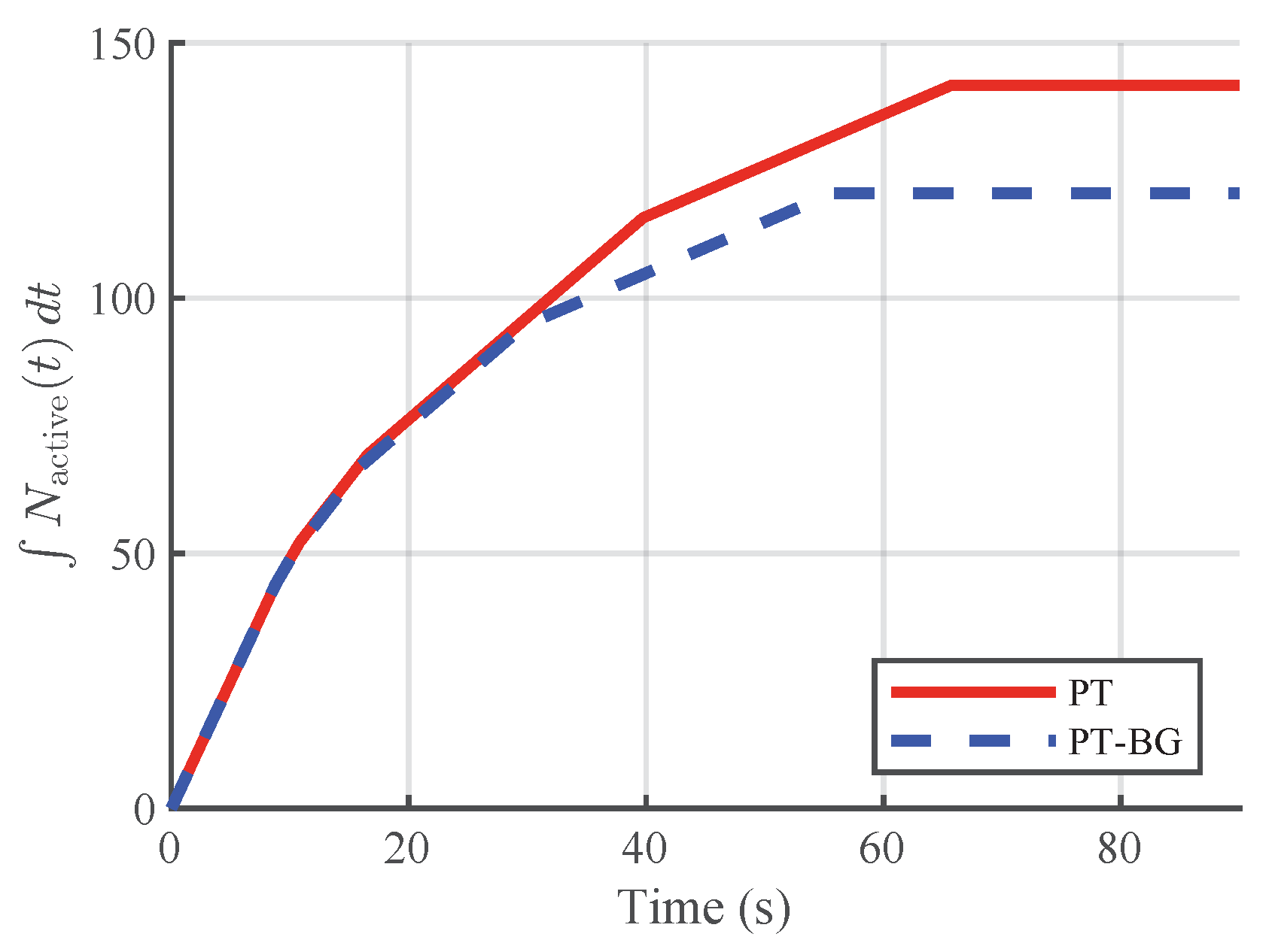
Figure 14 reports the cumulative inter-UAV safety-conflict exposure
E conf ( t ) = 0 t N active ( τ ) d τ ,
where N active ( t ) denotes the number of active inter-UAV safety-conflict pairs. This quantity measures the accumulated time for which the UAV team remains in locally crowded or near-boundary pairwise configurations. A lower value of E conf indicates that active pairwise conflicts are released more rapidly.
As shown in Figure 14, the PT-BG-ECBF-QP yields a consistently lower cumulative exposure than the PT-ECBF-QP after the initial crowding transient. This result does not imply that the BG term replaces the ECBF constraints or directly strengthens hard safety. Instead, it shows that, under the same hard safety constraints, the BG-preserving allocation redistributes the safety-induced correction in a way that more rapidly relieves local inter-UAV crowding. Therefore, the benefit of the BG-aware execution layer is a faster release from dense shell configurations, rather than a mere reduction in correction magnitude.

6.5. ROS-Based Implementation Validation

The preceding studies evaluate the proposed components through controlled numerical comparisons and ablations. To further examine the implementability of the complete sensing–estimation–control–safety pipeline, a ROS-based simulation is conducted using the same target-centered prescribed-shell objective. The purpose of this test is not to repeat the ablation study, but to verify that the AOA/EKF–PTESO interface, the radial–tangential nominal controller, and the PT-BG-ECBF-QP safety layer can be integrated in a middleware-level implementation while preserving the main closed-loop properties.
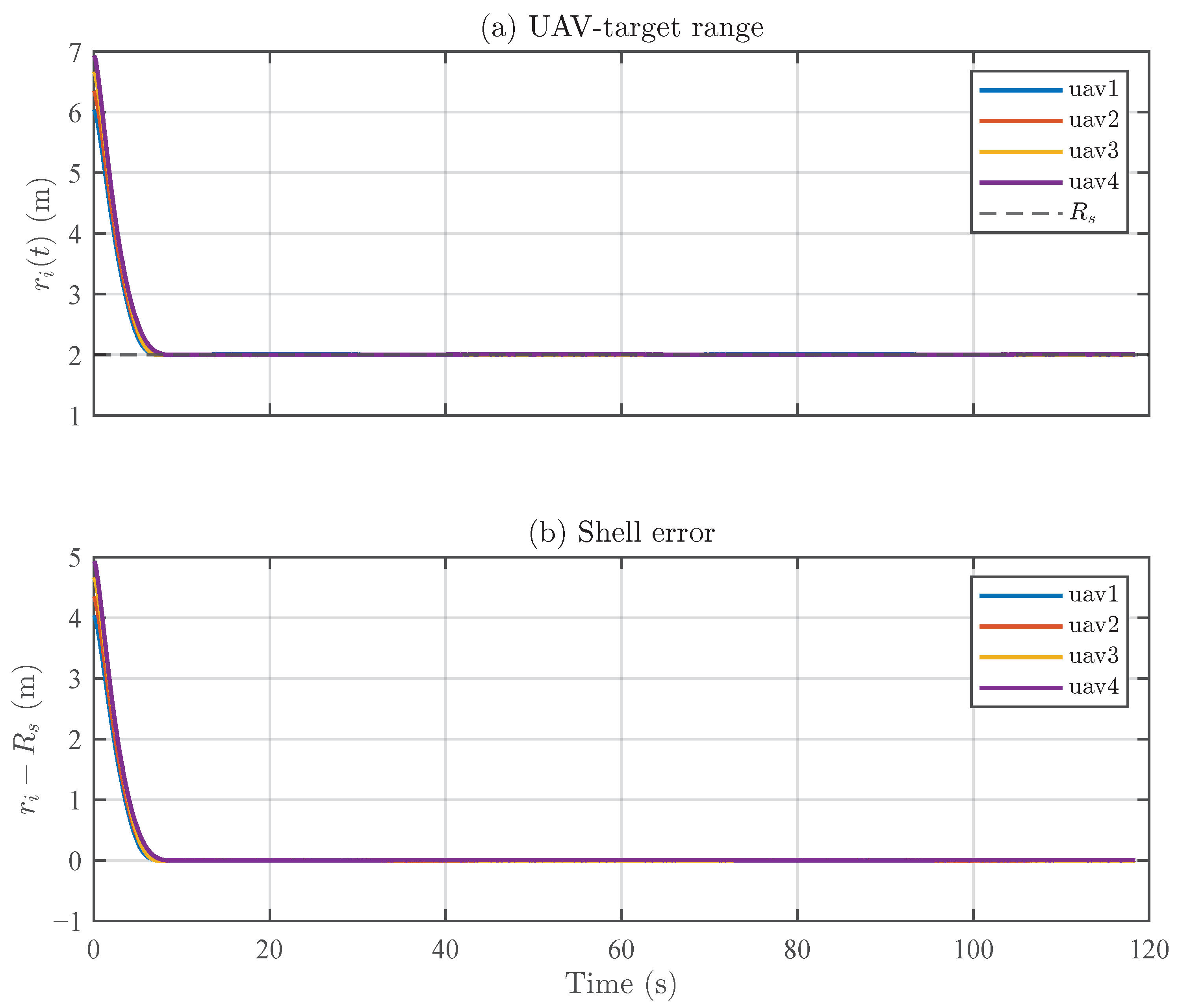
Figure 15 reports the prescribed-shell regulation performance in the ROS simulation. The UAV–target ranges r i ( t ) rapidly approach the prescribed shell radius R s , and the corresponding shell errors r i R s converge to a small neighborhood of zero. This confirms that the radial channel remains effective when the controller is driven by the ROS-level AOA/EKF–PTESO reconstruction interface.
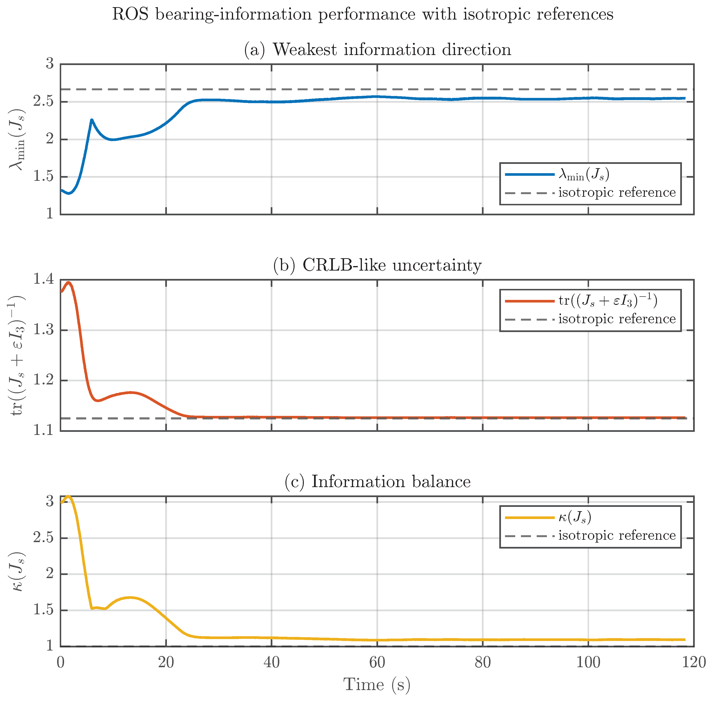
Figure 16 evaluates the resulting bearing-information performance. The shell-normalized bearing information matrix is computed as
J s = i = 1 N ( I 3 n i n i ) ,
and the dashed lines denote the isotropic shell-geometry references, namely λ min ( J s ) = 2 N / 3 , tr ( ( J s + ε I 3 ) 1 ) = 3 / ( 2 N / 3 + ε ) , and κ ( J s ) = 1 . For the four-UAV case, the isotropic reference is λ min ( J s ) = 8 / 3 . The weakest information direction increases toward the isotropic benchmark, while the CRLB-like trace and the condition number decrease toward their reference values. These results indicate that the ROS implementation not only preserves the prescribed shell, but also drives the simultaneous target-centered bearing directions toward a near-isotropic and information-efficient geometry.
Overall, the simulation results support the three main design components and their ROS-level integration. The metric study shows that the bearing-enclosure potential links information quality with directed and noncoplanar enclosure. The radius-invariance study verifies that the lifting compensates for the 1 / r i bearing-kinematic bias. The safety-stress studies show that, over the executed feasible trajectories, PT-BG-ECBF-QP maintains reported positive safety margins while better preserving the prescribed-shell and bearing-geometry objectives during active correction. The ROS-based validation further confirms that the AOA/EKF–PTESO–control–QP pipeline preserves shell regulation and bearing-information improvement in an integrated implementation.
The following real-world flight experiment further evaluates whether this integrated pipeline can be deployed on a physical Crazyflie-based multi-UAV platform.

6.6. Real-World Flight Experiment

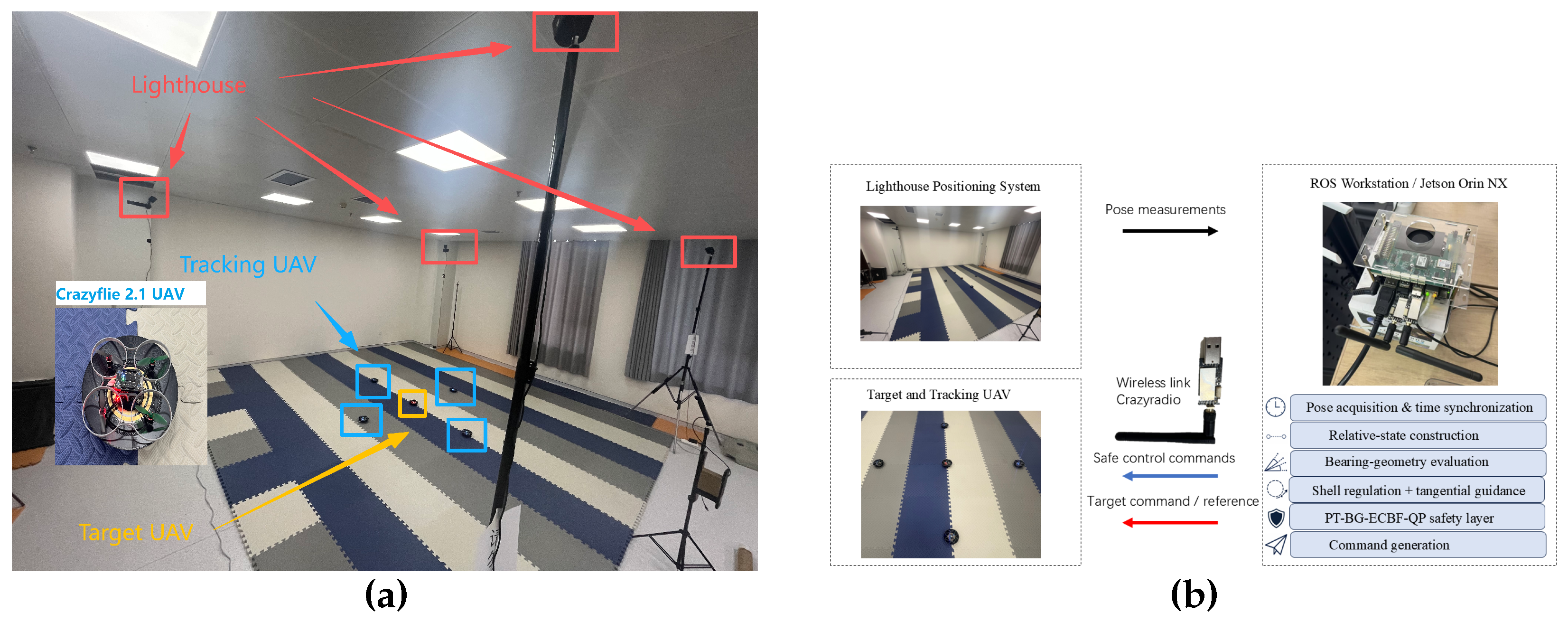
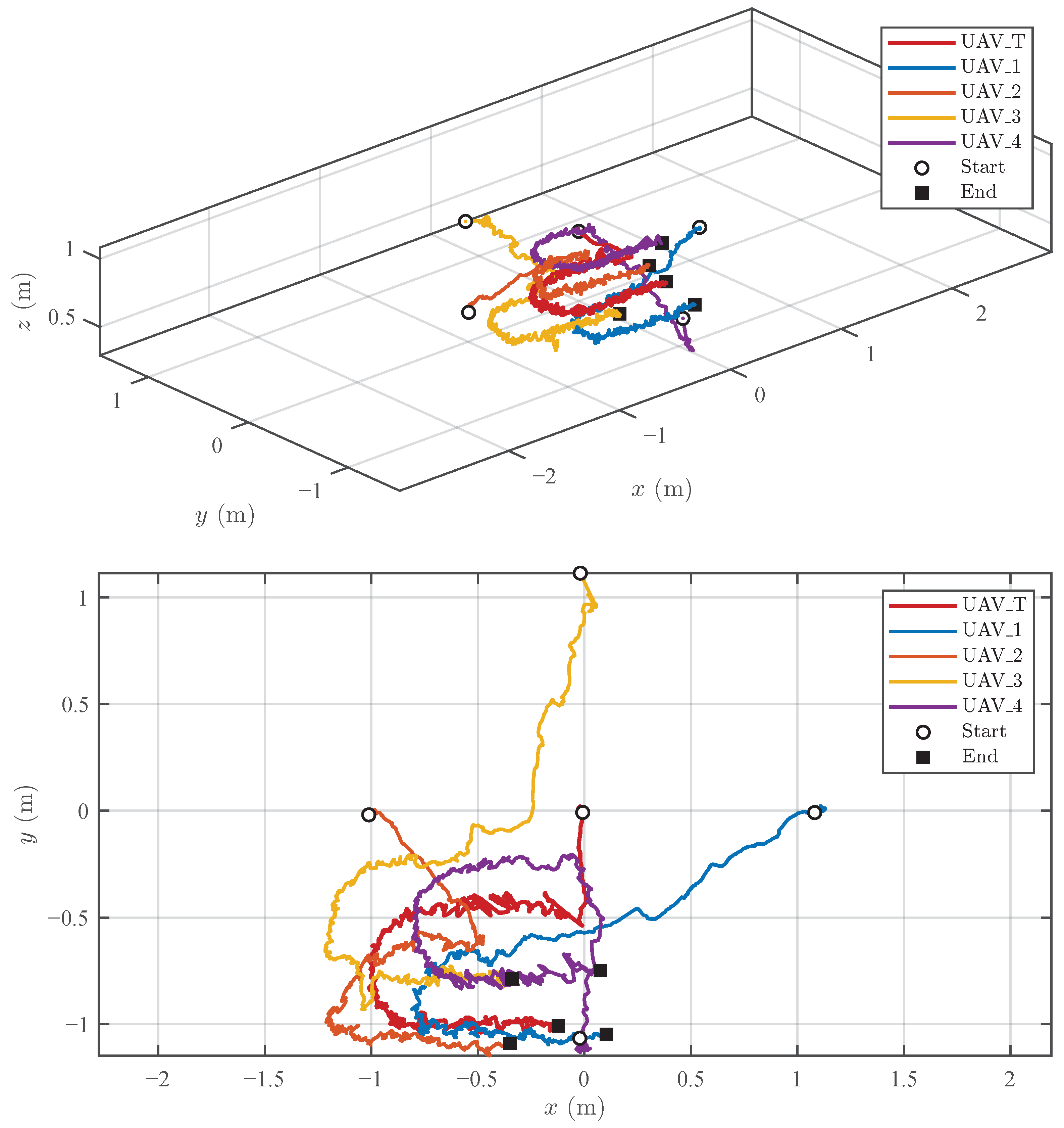
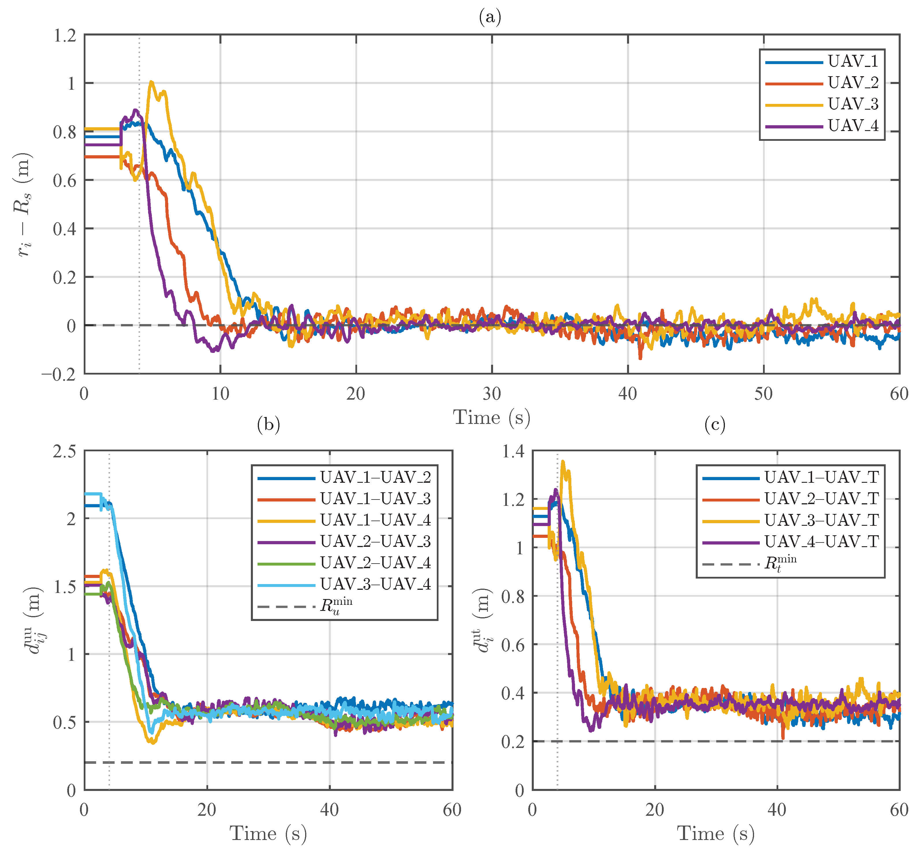
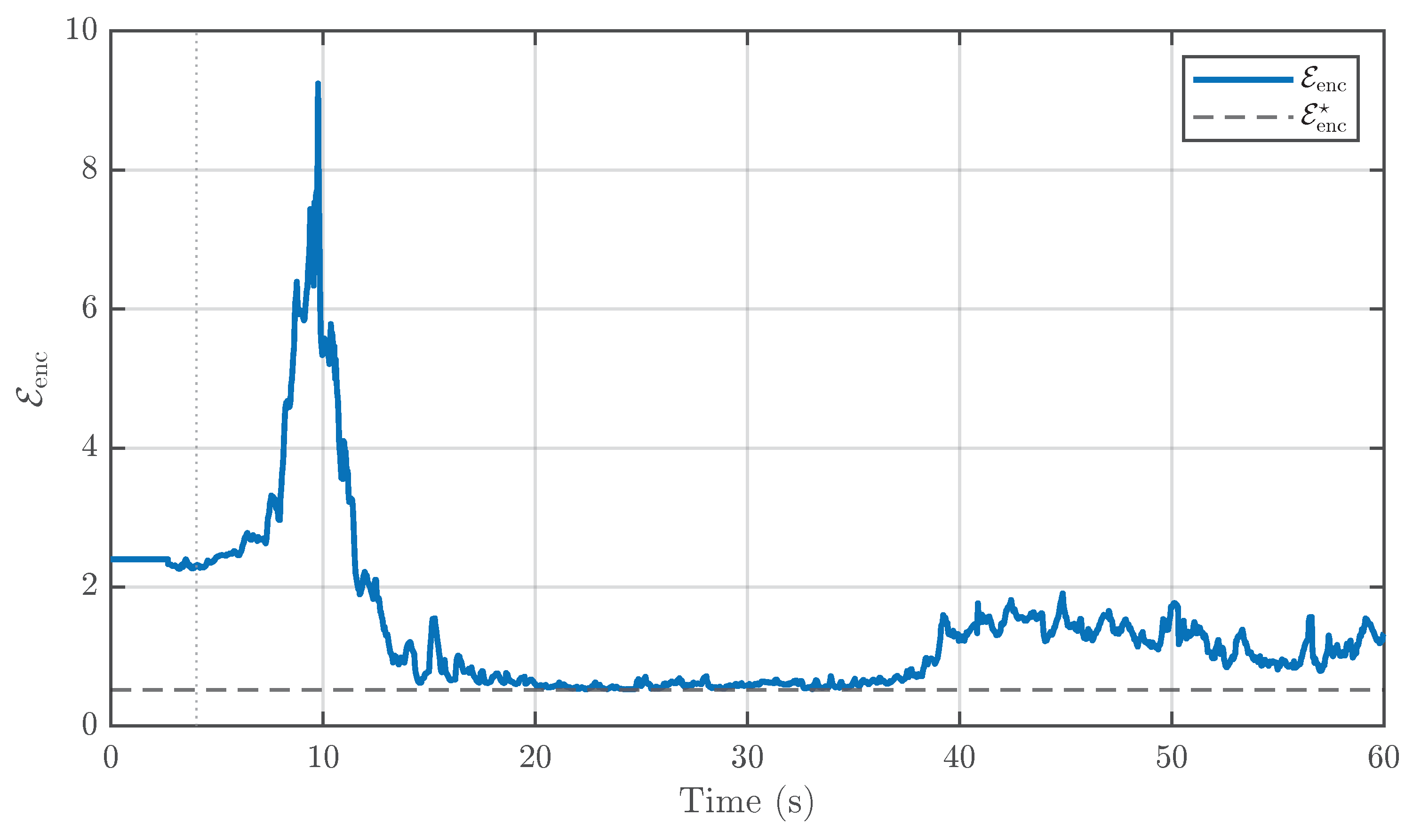
To further validate the practical feasibility of the proposed prescribed-shell bearing-geometry self-organization framework, a real-world indoor flight experiment was conducted on a multi-UAV platform. The experiment consisted of one target UAV and four active tracking UAVs. The target UAV executed a predefined reference maneuver in the flight arena, while the four tracking UAVs were controlled to maintain the prescribed sensing shell, reshape the target-centered bearing geometry, and satisfy the UAV–target and inter-UAV safety constraints. Unlike the preceding simulations and ROS-based validation, this experiment was carried out on physical Crazyflie 2.1 UAVs under practical positioning noise, wireless communication delays, low-level attitude-control errors, and actuator limitations.
Figure 17 shows the experimental platform and the corresponding system architecture. The lighthouse positioning system was used to provide the pose measurements of the target UAV and the four tracking UAVs. These measurements were transmitted to the ROS workstation for pose acquisition, time synchronization, and target-centered relative-state construction. Based on the reconstructed relative states, the proposed controller evaluated the bearing-enclosure potential, generated the radial shell-regulation and tangential bearing-geometry guidance commands, and then computed the safe executable commands through the PT-BG-ECBF-QP safety layer. The resulting commands were sent to the Crazyflie 2.1 UAVs through the Crazyradio wireless link. The recorded experimental data included the three-dimensional trajectories, UAV–target distances, inter-UAV distances, shell tracking errors, bearing-geometry indices, and command signals.
Figure 18 presents the recorded trajectories of the target UAV and the four tracking UAVs. The upper subplot gives the three-dimensional trajectories, while the lower subplot provides the top-view trajectories for a clearer visualization of the horizontal motion. The tracking UAVs start from different initial positions and move toward the neighborhood of the target-centered prescribed shell. During the flight, they maintain a cooperative spatial distribution around the moving target instead of simply following the same path. This result verifies that the proposed framework can be deployed on a real multi-UAV platform and can generate coordinated target-centered motion for multiple tracking UAVs.
Figure 19 shows the prescribed-shell regulation and safety performance in the real-world flight experiment. As shown in Figure 19a, the shell tracking errors of the four tracking UAVs rapidly decrease after the control is activated and then remain in a small neighborhood of zero. This indicates that the radial channel successfully drives the UAV–target distances toward the prescribed sensing radius R s on the physical platform. The small steady-state oscillations around the shell are mainly caused by indoor positioning noise, wireless command delay, and the response limitation of the low-level flight controller.
The safety results are shown in Figure 19b,c. The inter-UAV distances remain above the prescribed threshold R u min throughout the whole flight, and the UAV–target distances also remain above the target-standoff threshold R t min . Therefore, the PT-BG-ECBF-QP safety execution layer preserves both inter-UAV separation and target-standoff safety while allowing the tracking UAVs to approach and maintain the prescribed sensing shell. These real-world results are consistent with the safety objective in the proposed control formulation.
Figure 20 reports the real-world evolution of the bearing-enclosure potential E enc . The dashed reference value E enc is obtained by substituting the ideal balanced bearing configuration into the proposed moment–volume bearing-enclosure potential. For the four-tracking-UAV case, this reference configuration corresponds to a symmetric target-centered bearing distribution, where the first moment approaches zero, the second moment approaches the isotropic condition, and the triple-product volume remains nondegenerate. Therefore, E enc represents the expected lower reference level for the bearing-geometry objective under the prescribed-shell condition, rather than a separately measured experimental quantity.
At the beginning of the experiment, E enc is about 2.3, indicating that the initial bearing distribution is not yet close to the desired balanced enclosure. During the initial deployment stage, E enc temporarily increases and reaches a peak of approximately 9.2 around 10 s. This transient increase is caused by the rapid motion of the tracking UAVs from their initial positions toward the prescribed sensing shell, during which the target-centered bearing directions can temporarily become more uneven or nearly degenerate. After the tracking UAVs approach the prescribed shell and the tangential geometry-regulation mechanism becomes effective, E enc decreases rapidly. From approximately 15 s to 38 s, the value remains near 0.5–0.7, which is close to the reference level E enc and indicates that the bearing geometry has been significantly improved.
After approximately 40 s, E enc increases slightly and fluctuates around 1.0–1.6. Nevertheless, the final bearing-enclosure potential remains much lower than the initial transient peak and stays within a bounded low-value range. These results show that the proposed tangential bearing-geometry controller can effectively improve the target-centered bearing distribution in a real multi-UAV experiment, even under practical sensing and actuation imperfections.
Overall, the real-world flight experiment confirms the practical implementability of the proposed prescribed-shell bearing-geometry self-organization method. The four tracking UAVs can regulate their UAV–target distances to the prescribed sensing shell, maintain the inter-UAV and UAV–target safety margins, and improve the target-centered bearing geometry around a moving target UAV. Compared with the preceding numerical simulations and ROS-based validation, the real-world experiment further demonstrates that the proposed control framework can be implemented on a physical multi-UAV system under realistic sensing, communication, and actuation imperfections.

7. Discussion and Conclusions

In this work, the proposed framework separates radial sensing regulation from angular bearing-geometry organization. This differs fundamentally from traditional FIM/CRLB-based approaches, in which these two aspects are coupled. This separation is motivated by a key practical consideration in multi-UAV tracking: range reduction is often unsafe or infeasible, whereas angular redistribution is both safer and more informative. Accordingly, the predefined-time design is embedded in the radial shell-reaching channel of the proposed active-perception framework. It specifies the time scale for establishing the admissible sensing shell, while the tangential channel improves the target-centered bearing geometry on the assigned shell. In this way, the radial and tangential channels play complementary roles in prescribed-shell bearing-geometry self-organization. The moment–volume bearing-enclosure potential E enc is constructed to operationalize this separation by acting directly on unit bearing directions. Several assumptions and limitations should be acknowledged. First, the predefined-time radial shell-reaching and ECBF safety guarantees are derived under QP feasibility and nominal reconstruction after the PTESO transient. In the noisy bearing-only implementation, bounded reconstruction errors enter the closed-loop system as perturbations. Therefore, when estimation errors become large or safety, input, and shell-reaching requirements persistently conflict, robust QP margins, constraint relaxation, or fallback mechanisms may be needed. Second, the current method requires centralized QP solving with global bearing information. A distributed implementation would be necessary for large-scale or communication-limited scenarios. Third, unobstructed line-of-sight and unlimited field of view are assumed, which may not hold in cluttered or urban environments. Extending the framework to handle occlusions and limited FOV is considered an important direction. Compared with unnormalized tangential lifting, the proposed radius-normalized mechanism achieves nearly radius-independent bearing dynamics, as verified in Section 6.3. Compared with standard ECBF-QP, the PT-BG-ECBF-QP better preserves the nominal radial–tangential command, leading to faster shell convergence and less suppression of geometry-improving motion under safety-critical conditions. The complete AOA/EKF–PTESO–control–QP pipeline is further confirmed via ROS-based validation to be implementable in a realistic middleware environment. The real-world flight experiment with one target UAV and four tracking UAVs further verifies the practical deployability of the proposed framework on a physical multi-UAV platform under positioning noise, wireless communication delays, low-level attitude-control errors, and actuator limitations.
In conclusion, a prescribed-shell bearing-geometry self-organization framework was proposed for multi-UAV bearing-only active tracking. Subject to QP feasibility and bounded estimation errors, radial shell convergence, practical bearing-geometry descent, safety forward invariance, and closed-loop boundedness were established through theoretical analysis. The effectiveness of the proposed method was demonstrated via simulations, ablation studies, ROS-based validation, and a real-world flight experiment. Compared with conventional approaches, more consistent prescribed-shell convergence, better bearing-geometry organization, and less disruption from safety filtering were achieved. Future work will focus on distributed implementation, fully onboard bearing-sensor experiments, and handling field-of-view and occlusion constraints.

Author Contributions

Conceptualization, H.L. and M.W.; methodology, H.L., C.C., and Z.R.; software, H.L. and Z.R.; validation, H.L. and C.C.; formal analysis, H.L. and Z.R.; investigation, H.L.; resources, M.W. and J.Y.; data curation, H.L.; writing—original draft preparation, H.L.; writing—review and editing, C.C., Z.R. and M.W.; supervision, M.W.; project administration, M.W.; funding acquisition, M.W. and J.Y. All authors have read and agreed to the published version of the manuscript.

Funding

This research was funded by the Major National Science and Technology Special Project of China, grant number 2024ZD1002604; the Excellent Youth Science Fund Project (Overseas) of Shandong Province, China, grant number 2023HWYQ-029; the Youth Project of Natural Science Foundation of Shandong Province, China, grant number ZR2023QE127; the Guangdong Basic and Applied Basic Research Foundation, grant number 2023A1515110509; and the Gansu Province Postdoctoral Fund, grant number 24JRRA219.

Institutional Review Board Statement

Not applicable.

Informed Consent Statement

Not applicable.

Data Availability Statement

The simulation data and MATLAB codes used in this study are available from the corresponding author upon reasonable request.

Conflicts of Interest

The authors declare no conflicts of interest.

References

  1. Aidala, V.J. Kalman Filter Behavior in Bearings-Only Tracking Applications. IEEE Trans. Aerosp. Electron. Syst. 1979, AES-15, 29–39. [Google Scholar] [CrossRef]
  2. Aidala, V.J.; Hammel, S.E. Utilization of Modified Polar Coordinates for Bearings-Only Tracking. IEEE Trans. Autom. Control 1983, 28, 283–294. [Google Scholar] [CrossRef]
  3. Nardone, S.C.; Lindgren, A.G.; Gong, K.F. Fundamental Properties and Performance of Conventional Bearings-Only Target Motion Analysis. IEEE Trans. Autom. Control 1984, 29, 775–787. [Google Scholar] [CrossRef]
  4. Guan, X.; Yiu, K.F.C.; Li, B.; Zeng, Y.; Zhang, R. 3D Trajectory Optimization for Fixed-Wing UAV Communications with Full UAV Dynamics. IEEE Trans. Veh. Technol. 2025, 74, 15401–15415. [Google Scholar] [CrossRef]
  5. Li, B.; Zhang, H.; Rong, Y.; Han, Z. A Control-Based Design of Beamforming and Trajectory for UAV-Enabled ISAC System. IEEE Trans. Wirel. Commun. 2026, 25, 3469–3484. [Google Scholar] [CrossRef]
  6. Li, B.; Zhang, W.; Shi, M. A Distributionally Robust Optimization-Based Stochastic Self-Triggered Model Predictive Control. IEEE Trans. Syst. Man Cybern. Syst. 2026, 56, 2699–2707. [Google Scholar] [CrossRef]
  7. Li, B.; Lin, M.; Shi, M. Distributed Distributionally Robust Model Predictive Control. Int. J. Robust Nonlinear Control 2026, 36, 1652–1664. [Google Scholar] [CrossRef]
  8. Chen, Z.; Wang, F.; Zhang, H.; Chen, Z.; He, Q. Performance and Safety Evaluation of Rack Vehicle in Mountainous Regions Under Pulsating Wind Loads. Mech. Based Des. Struct. Mach. 2026, 54, 2553887. [Google Scholar] [CrossRef]
  9. Lv, Z.; Zhao, Q.; Sun, X.M.; Wu, Y. Finite-Time Control Design for a Coaxial Tilt-Rotor UAV. IEEE Trans. Ind. Electron. 2024, 71, 16132–16142. [Google Scholar] [CrossRef]
  10. Chen, Z.; Li, B.; Wang, B. Robust Stability Design for Inverters Using Phase Lag in Proportional-Resonant Controllers. IEEE Trans. Ind. Electron. 2024, 72, 2655–2668. [Google Scholar] [CrossRef]
  11. Mušicki, D.; Evans, R.J.; Stanković, S. Bearings-Only Single-Sensor Target Tracking Using Gaussian Mixtures. Automatica 2009, 45, 2088–2092. [Google Scholar] [CrossRef]
  12. Davey, S.J.; Rutten, M.G.; Cheung, B. A Comparison of Bearings-Only Track Initiation Techniques. IEEE Trans. Aerosp. Electron. Syst. 2013, 49, 743–760. [Google Scholar]
  13. Ning, Z.; Zhang, Y.; Li, J.; Chen, Z.; Zhao, S. A Bearing-Angle Approach for Unknown Target Motion Analysis Based on Visual Measurements. Int. J. Robot. Res. 2024, 43, 1228–1249. [Google Scholar] [CrossRef]
  14. Zheng, C.; Mi, Y.; Guo, H.; Chen, H.; Lin, Z.; Zhao, S. Optimal Spatial–Temporal Triangulation for Bearing-Only Cooperative Motion Estimation. Automatica 2025, 175, 112216. [Google Scholar] [CrossRef]
  15. Le Cadre, J.P.; Laurent-Michel, S. Optimizing the Receiver Maneuvers for Bearings-Only Tracking. Automatica 1999, 35, 591–606. [Google Scholar] [CrossRef]
  16. Oshman, Y.; Davidson, P. Optimization of Observer Trajectories for Bearings-Only Target Localization. IEEE Trans. Aerosp. Electron. Syst. 1999, 35, 892–902. [Google Scholar] [CrossRef]
  17. He, S.; Shin, H.S.; Tsourdos, A. Trajectory Optimization for Target Localization with Bearing-Only Measurement. IEEE Trans. Robot. 2019, 35, 653–668. [Google Scholar] [CrossRef]
  18. Li, J.; Ning, Z.; He, S.; Lee, C.H.; Zhao, S. Three-Dimensional Bearing-Only Target Following via Observability-Enhanced Helical Guidance. IEEE Trans. Robot. 2023, 39, 1509–1526. [Google Scholar] [CrossRef]
  19. Wang, Y.; Wu, Z.; Piao, H.; He, S. Three-Dimensional Bearing-Only Helical Homing Guidance. IEEE Trans. Aerosp. Electron. Syst. 2024, 60, 4794–4807. [Google Scholar] [CrossRef]
  20. Martínez, S.; Bullo, F. Optimal Sensor Placement and Motion Coordination for Target Tracking. Automatica 2006, 42, 661–668. [Google Scholar] [CrossRef]
  21. Zhao, S.; Chen, B.M.; Lee, T.H. Optimal Sensor Placement for Target Localisation and Tracking in 2D and 3D. Int. J. Control 2013, 86, 1687–1704. [Google Scholar] [CrossRef]
  22. Zhao, S.; Chen, B.M.; Lee, T.H. Optimal Deployment of Mobile Sensors for Target Tracking in 2D and 3D Spaces. IEEE/CAA J. Autom. Sin. 2014, 1, 24–42. [Google Scholar][Green Version]
  23. Moreno-Salinas, D.; Pascoal, A.M.; Aranda, J. Sensor Networks for Optimal Target Localization with Bearings-Only Measurements in Constrained Three-Dimensional Scenarios. Sensors 2013, 13, 10386–10417. [Google Scholar] [CrossRef] [PubMed]
  24. Vander Hook, J.; Tokekar, P.; Isler, V. Cautious Greedy Strategy for Bearing-Only Active Localization: Analysis and Field Experiments. J. Field Robot. 2014, 31, 296–318. [Google Scholar] [CrossRef]
  25. Dogancay, K.; Hmam, H. Optimal Angular Sensor Separation for AOA Localization. Signal Process. 2008, 88, 1248–1260. [Google Scholar] [CrossRef]
  26. Bishop, A.N.; Fidan, B.; Anderson, B.D.O.; Doğançay, K.; Pathirana, P.N. Optimality Analysis of Sensor-Target Geometries in Passive Localization: Part 1–Bearing-Only Localization. Signal Process. 2010, 90, 1556–1567. [Google Scholar]
  27. Ames, A.D.; Xu, X.; Grizzle, J.W.; Tabuada, P. Control Barrier Function Based Quadratic Programs for Safety Critical Systems. IEEE Trans. Autom. Control 2017, 62, 3861–3876. [Google Scholar] [CrossRef]
  28. Nguyen, Q.; Sreenath, K. Exponential Control Barrier Functions for Enforcing High Relative-Degree Safety-Critical Constraints. In Proceedings of the American Control Conference, Boston, MA, USA, 6–8 July 2016; pp. 322–328. [Google Scholar] [CrossRef]
  29. Xiao, W.; Belta, C. High-Order Control Barrier Functions. IEEE Trans. Autom. Control 2022, 67, 3655–3662. [Google Scholar] [CrossRef]
  30. Wang, L.; Ames, A.D.; Egerstedt, M. Safety Barrier Certificates for Collisions-Free Multirobot Systems. IEEE Trans. Robot. 2017, 33, 661–674. [Google Scholar] [CrossRef]
  31. Glotfelter, P.; Cortés, J.; Egerstedt, M. Nonsmooth Barrier Functions with Applications to Multi-Robot Systems. IEEE Control Syst. Lett. 2017, 1, 310–315. [Google Scholar] [CrossRef]
  32. Zhang, S.; So, O.; Garg, K.; Fan, C. GCBF+: A Neural Graph Control Barrier Function Framework for Distributed Safe Multiagent Control. IEEE Trans. Robot. 2025, 41, 1533–1552. [Google Scholar] [CrossRef]
  33. Ye, M.; Anderson, B.D.O.; Yu, C. Bearing-Only Measurement Self-Localization, Velocity Consensus and Formation Control. IEEE Trans. Aerosp. Electron. Syst. 2017, 53, 575–586. [Google Scholar]
  34. Yin, Q.; Xu, C.; Zhou, P.; Huang, D.; Xu, W. Dual-UAV Cooperative Bearing-Only Target Localization Based on Multi-Level Box Particle Filter. Digit. Signal Process. 2026, 168, 105572. [Google Scholar] [CrossRef]
  35. Zhao, S.; Zelazo, D. Bearing Rigidity and Almost Global Bearing-Only Formation Stabilization. IEEE Trans. Autom. Control 2016, 61, 1255–1268. [Google Scholar] [CrossRef]
  36. Zhao, S.; Zelazo, D. Localizability and Distributed Protocols for Bearing-Based Network Localization in Arbitrary Dimensions. Automatica 2016, 69, 334–341. [Google Scholar] [CrossRef]
  37. Zhao, S.; Zelazo, D. Translational and Scaling Formation Maneuver Control via a Bearing-Based Approach. IEEE Trans. Control Netw. Syst. 2017, 4, 429–438. [Google Scholar] [CrossRef]
  38. Trinh, M.H.; Zhao, S.; Sun, Z.; Zelazo, D.; Anderson, B.D.O.; Ahn, H.S. Bearing-Based Formation Control of a Group of Agents With Leader-First Follower Structure. IEEE Trans. Autom. Control 2019, 64, 598–613. [Google Scholar] [CrossRef]
  39. Trinh, M.H.; Ahn, H.S.; Anderson, B.D.O. Robust Tracking Control of Bearing-Constrained Leader–Follower Formation. Automatica 2021, 131, 109733. [Google Scholar]
  40. Dogancay, K.; Hmam, H. UAV Path Optimization for Angle-Only Self-Localization and Target Tracking Based on the Bayesian Fisher Information Matrix. Sensors 2024, 24, 3120. [Google Scholar] [CrossRef] [PubMed]
  41. Wang, S.; Li, Y.; Qi, G.; Sheng, A. Optimal Geometry and Motion Coordination for Multisensor Target Tracking with Bearings-Only Measurements. Sensors 2023, 23, 6408. [Google Scholar] [CrossRef] [PubMed]
  42. Xu, S.; Dogancay, K. Optimal Sensor Placement for 3-D Angle-of-Arrival Target Localization. IEEE Trans. Aerosp. Electron. Syst. 2017, 53, 1196–1211. [Google Scholar] [CrossRef]
  43. Fang, X.; Li, J. Frame Theory for Optimal Sensor Augmentation Problem of AOA Localization. IEEE Signal Process. Lett. 2018, 25, 1310–1314. [Google Scholar] [CrossRef]
  44. Agrawal, A.; Sreenath, K. Discrete Control Barrier Functions for Safety-Critical Control of Discrete Systems with Application to Bipedal Robot Navigation. Robot. Sci. Syst. 2017, 13, 1–10. [Google Scholar]
  45. Zeng, J.; Zhang, B.; Sreenath, K. Safety-Critical Model Predictive Control with Discrete-Time Control Barrier Function. In Proceedings of the American Control Conference, New Orleans, LA, USA, 25–28 May 2021; pp. 3882–3889. [Google Scholar]
  46. Kolathaya, S.; Ames, A.D. Input-to-State Safety with Control Barrier Functions. IEEE Control Syst. Lett. 2019, 3, 108–113. [Google Scholar] [CrossRef]
  47. Alan, A.; Taylor, A.J.; He, C.R.; Orosz, G.; Ames, A.D. Safe Controller Synthesis with Tunable Input-to-State Safe Control Barrier Functions. IEEE Control Syst. Lett. 2022, 6, 908–913. [Google Scholar]
  48. Garg, K.; Usevitch, J.; Breeden, J.; Black, M.; Agrawal, D.; Parwana, H.; Panagou, D. Advances in the Theory of Control Barrier Functions: Addressing Practical Challenges in Safe Control Synthesis for Autonomous and Robotic Systems. Annu. Rev. Control 2024, 57, 100945. [Google Scholar] [CrossRef]
  49. Knödler, L.; So, O.; Yin, J.; Black, M.; Serlin, Z.; Tsiotras, P.; Alonso-Mora, J.; Fan, C. Safety on the Fly: Constructing Robust Safety Filters via Policy Control Barrier Functions at Runtime. IEEE Robot. Autom. Lett. 2025, 10, 10058–10065. [Google Scholar] [CrossRef]
  50. Ning, B.; Han, Q.L.; Zuo, Z.; Ding, L. Accelerated Secondary Frequency Regulation and Active Power Sharing for Islanded Microgrids With External Disturbances: A Fully Distributed Approach. Automatica 2025, 174, 112146. [Google Scholar] [CrossRef]
  51. Jin, X. Adaptive Fixed-Time Control for MIMO Nonlinear Systems With Asymmetric Output Constraints Using Universal Barrier Functions. IEEE Trans. Autom. Control 2019, 64, 3046–3053. [Google Scholar] [CrossRef]
Figure 1. AOA bearing-only measurement geometry. The target direction can be represented by azimuth and elevation angles, while the control design uses the corresponding target-centered unit bearing vector.
Actuators 15 00365 g001
Figure 2. Target-centered prescribed-shell bearing geometry. The UAVs regulate their target-centered distances toward the prescribed sensing radius R s , while the tangential motion reshapes the bearing directions on the shell. The target-standoff constraint r i R t min and the inter-UAV separation constraint d i j R u min define the hard safety requirements. The blue outer sphere denotes the prescribed sensing shell of radius R s , the red inner sphere denotes the target-standoff boundary of radius R t min , and the red dot denotes the target. The blue UAV icons denote the tracking UAVs, the faded gray UAV icons and dashed arrows indicate approaching motion toward the prescribed shell, the green arrow indicates the tangential bearing update on the shell, and the orange arc illustrates the inter-UAV separation requirement d i j R u min .
Actuators 15 00365 g002
Figure 3. Closed-loop architecture with the AOA/EKF–PTESO estimation interface. Bearing-only AOA measurements are processed by the AOA/EKF and PTESO to construct p ^ r , i , v ^ r , i , and w ^ i . The R/T controller generates u d , i , and the PT-BG-ECBF-QP produces the executed command u s , i .
Actuators 15 00365 g003
Figure 4. Intuition of the bearing-enclosure potential on the unit sphere. The four panels show representative bearing layouts during geometry improvement: (a) one-sided trailing, (b) coplanar spread, (c) transitional distribution, and (d) enclosed distribution. Blue dots denote representative unit bearing directions on the sphere, and dashed lines indicate the geometric connections used to illustrate the moment and volume effects. The first-moment term rejects one-sided trailing layouts, the second-moment term promotes angular isotropy, and the third-order volume term encourages noncoplanar enclosure.
Actuators 15 00365 g004
Figure 5. AOA/EKF–PTESO interface validation. Panels (ac) compare the representative position, velocity, and acceleration signals reconstructed through the AOA/EKF–PTESO interface with the corresponding reference signals, while panel (d) compares the mean shell-tracking error of the closed loop driven by the true-state input and by the AOA/EKF–PTESO interface. The results show that the estimation interface can be integrated into the proposed control architecture while preserving satisfactory shell-tracking performance.
Actuators 15 00365 g005
Figure 6. Overall three-dimensional trajectories in the main proposed scenario. The UAVs start from a rear-side lower region with layered initial radii and form a target-centered bearing enclosure while tracking the maneuvering target.
Actuators 15 00365 g006
Figure 7. Radial shell tracking in the main scenario. The target-centered distances r i converge to the prescribed sensing radius R s , while the target-standoff boundary R t min is respected. The vertical dashed line denotes the prescribed radial shell-reaching horizon T r = 8.00 s.
Actuators 15 00365 g007
Figure 8. Predefined-time radial shell-reaching validation under different initial UAV position configurations. The curves show e max ( t ) = max i | r i ( t ) R s | for different normalized initial radii, and the vertical dashed line denotes the prescribed radial shell-reaching horizon T r = 8.00 s.
Actuators 15 00365 g008
Figure 9. Target-standoff and inter-UAV safety margins in the main scenario. The zero line denotes the safety boundary.
Actuators 15 00365 g009
Figure 10. Evolution of the bearing-enclosure geometry. The proposed moment–volume potential E enc decreases, while the noncoplanar enclosure volume V 3 increases and the weakest information direction λ min ( J s ) approaches the isotropic reference.
Actuators 15 00365 g010
Figure 11. Metric ablation in a metric-sensitive case. (a) Evolution of the unified bearing-enclosure potential E enc . (b) Evolution of the minimum eigenvalue λ min ( J ¯ b ) of the normalized bearing-information matrix. (c) Evolution of the directed bearing bias n ¯ . (d) Evolution of the triple-product volume V 3 .
Actuators 15 00365 g011
Figure 12. Radius-normalized tangential lifting validation. The direction-space speed s n ( t ) and descent-rate coefficient c b ( t ) are compared under radius-normalized and non-normalized tangential implementations. With the proposed lifting, the curves obtained under different radius scales nearly overlap, whereas the non-normalized implementation exhibits radius-dependent attenuation and separated descent profiles.
Actuators 15 00365 g012
Figure 13. QP safety execution under a stress case. The nominal command without ECBF-QP violates the inter-UAV safety boundary, whereas the PT-BG-ECBF-QP maintains a positive reported inter-UAV safety margin over the executed trajectory. The active constraint and correction profiles confirm that the QP is frequently engaged; the shell-error comparison shows the role of the PT shell component.
Actuators 15 00365 g013
Figure 14. Cumulative inter-UAV safety-conflict exposure in the dense ten-UAV shell-crowding case. The plotted quantity is E conf ( t ) = 0 t N active ( τ ) d τ , where N active ( t ) is the number of active inter-UAV safety-conflict pairs. A lower curve indicates that the team leaves locally crowded and near-boundary configurations more quickly. The PT-BG-ECBF-QP reduces the cumulative exposure compared with the PT-ECBF-QP, showing that the BG-preserving allocation accelerates the release of local inter-UAV safety conflicts under the same hard safety constraints.
Actuators 15 00365 g014
Figure 15. ROS-based validation of prescribed-shell regulation. (a) UAV–target ranges r i ( t ) converge to the prescribed shell radius R s . (b) The shell errors r i R s converge to a small neighborhood of zero, showing accurate radial shell regulation in the ROS implementation.
Actuators 15 00365 g015
Figure 16. ROS-based validation of bearing-information performance with isotropic references. (a) The weakest information direction λ min ( J s ) increases toward the isotropic benchmark. (b) The CRLB-like uncertainty tr ( ( J s + ε I 3 ) 1 ) decreases toward the isotropic reference. (c) The information-balance index κ ( J s ) approaches the ideal isotropic value.
Actuators 15 00365 g016
Figure 17. Real-world experimental setup and system architecture. (a) Indoor Crazyflie-based multi-UAV flight platform with one target UAV and four active tracking UAVs. (b) Experimental system framework implemented on the ROS workstation and Jetson Orin NX. The Lighthouse positioning system provides pose measurements, the ground station constructs the relative states and computes the proposed bearing-geometry-guided control law, and the safe commands are transmitted to the UAVs through the Crazyradio wireless link. In subfigure (a), red, blue, and yellow annotations indicate the Lighthouse positioning devices, tracking UAVs, and target UAV, respectively. In subfigure (b), dashed boxes distinguish the positioning system, UAV platform, and computing workstation, arrows indicate measurement, communication, and command flows, and the blue blocks denote the main computation and control modules.
Actuators 15 00365 g017
Figure 18. Real-world flight trajectories of the target UAV and four active tracking UAVs. The upper subplot shows the three-dimensional trajectories, and the lower subplot shows the corresponding top-view trajectories. The circles and squares denote the starting and ending positions, respectively.
Actuators 15 00365 g018
Figure 19. Real-world prescribed-shell and safety performance. (a) Shell tracking errors r i R s of the four tracking UAVs. (b) Inter-UAV distances d i j u u with the minimum separation threshold R u min . (c) UAV–target distances d i u t with the target-standoff threshold R t min .
Actuators 15 00365 g019
Figure 20. Real-world bearing-geometry performance. The solid curve denotes the measured bearing-enclosure potential E enc , and the dashed line denotes the ideal reference value E enc computed from the desired balanced bearing configuration.
Actuators 15 00365 g020
Table 1. Qualitative comparison with representative related approaches.
Method CategoryMain Limitation for This ProblemMain RoleDifference of the Proposed Method
Bearing-only EKF/PLKF and filtering methodsBearing geometry is mainly evaluated passively; safety and motion shaping are usually separateEstimate target states from AOA measurementsActively reshapes target-centered bearing geometry through control
FIM/CRLB/GDOP-based optimizationRange attenuation and angular diversity are often coupledOptimize sensing geometry using information metricsSeparates radial shell regulation from tangential angular-geometry improvement
Circular, circumnavigation, or helical guidanceUsually imposes a fixed orbit or guidance templateImprove line-of-sight excitation through prescribed patternsDoes not require a fixed circular or helical trajectory
Bearing-based formation controlUsually requires preassigned slots, desired bearing patterns, or role allocationRegulate bearings according to a desired formation shapeSelf-organizes the bearing distribution without assigning each UAV to a fixed target-centered position
Standard CBF-QP safety filtersUsually does not preserve radial shell reaching and tangential geometry improvement separatelyModify nominal commands to satisfy safety constraintsUses radial–tangential allocation to preserve both roles when feasible
Proposed frameworkPairwise constraints still scale with the number of UAV pairsPrescribed-shell bearing-geometry self-organization with safety-critical executionCombines moment–volume bearing geometry, prescribed shell regulation, and geometry-preserving ECBF-QP execution
Table 2. Simulation setup.
ParameterValue
Number of UAVs N4
Simulation horizon T120 s
Sampling time Δ t 0.02 s
Prescribed shell radius R s 40 m
Prescribed radial shell-reaching horizon T r 8.00 s
Initial radii r i ( 0 ) 84, 94, 104, 114 m
Normalized initial radii r i ( 0 ) / R s 2.10 , 2.35 , 2.60 , 2.85
Computed initial minimum inter-UAV distance d min ( 0 ) 25.94 m
Table 3. Performance statistics.
MetricValue
Initial radii r i ( 0 ) (m) 84 , 94 , 104 , 114
Normalized initial radii r i ( 0 ) / R s 2.10 , 2.35 , 2.60 , 2.85
Computed initial minimum inter-UAV distance d min ( 0 ) (m) 25.94
Prescribed radial shell-reaching horizon T r (s) 8.00
Measured shell-reaching time T s (s) 7.40
Enclosure time T enc (s) 89.04
Final directed bias n ¯ 1.504 × 10 4
Final enclosure volume V 3 0.5926
Final λ min ( S n ) 0.3332
Final κ ( S n ) 1.001
Final front–back distribution 2 / 2
Minimum target margin (m) 35.13
Minimum pair margin (m) 8.174
Mean shell error after measured T s (m) 0.07448
QP feasible ratio 0.9762
Table 4. Metric-ablation summary in the metric-sensitive case.
Method T enc (s)Final c n Final V 3 Final λ min ( S n ) Final κ ( S n ) Front–Back
Full 99.14 1.555 × 10 4 0.5926 0.3332 1.001 2 / 2
No first 0.5773 0.5926 0.3332 1.001 0 / 4
No second 103.7 2.181 × 10 4 0.5924 0.3269 1.030 2 / 2
No volume 103.7 1.769 × 10 4 0.5926 0.3326 1.003 2 / 2
Spectral 0.5773 0.5925 0.3301 1.020 0 / 4
Table 5. Static benchmark against the theoretical shell optimum.
Case λ min J A κ det c n V 3
Proposed2.66581.12501.000618.963 3.69 × 10 4 0.59259
Theoretical optimum2.66671.12501.000018.96300.59259
J A = tr ( ( J s + ε I 3 ) 1 ) , κ = κ ( J s ) , det = det ( J s + ε I 3 ) , and c n = n ¯ .
Table 6. QP safety-stress summary.
MethodMin Pair Margin (m)QP Active RatioFeasible RatioMean Shell Error (m) T enc (s)Max Correction
Nominal 0.4557 0.0375 1.0000 0.0970 96.84 3.69
Standard ECBF-QP 0.00113 0.0477 1.0000 0.0970 97.24 3.69
BG-ECBF-QP 0.00055 0.0463 0.9743 0.0948 98.24 3.59
PT-BG-ECBF-QP 0.01313 0.9507 0.9588 0.0645 99.64 41.37
PT-ECBF-QP 0.00689 0.9685 0.9762 0.0723 98.36 41.30
Disclaimer/Publisher’s Note: The statements, opinions and data contained in all publications are solely those of the individual author(s) and contributor(s) and not of MDPI and/or the editor(s). MDPI and/or the editor(s) disclaim responsibility for any injury to people or property resulting from any ideas, methods, instructions or products referred to in the content.