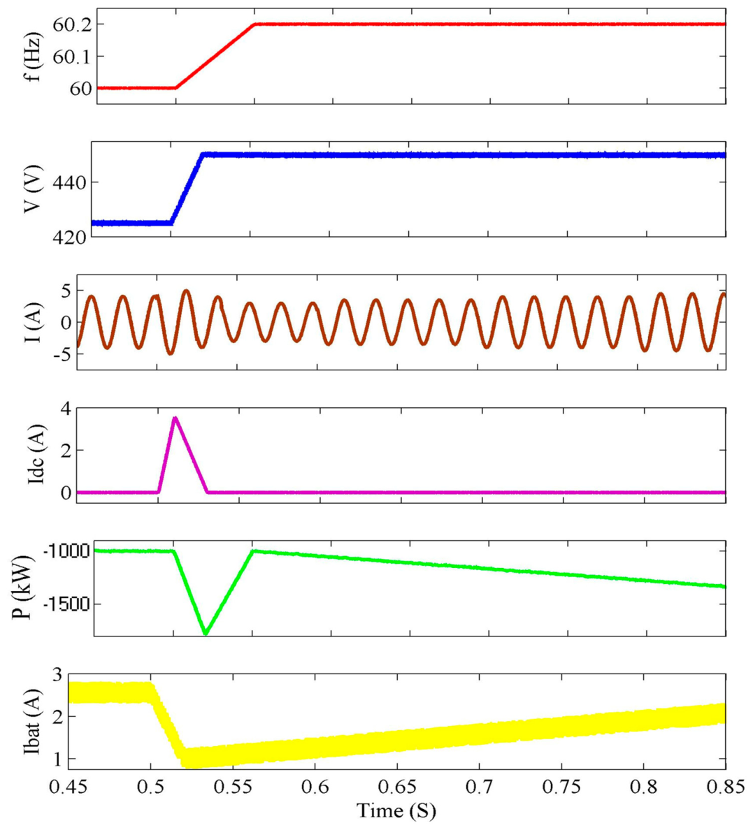
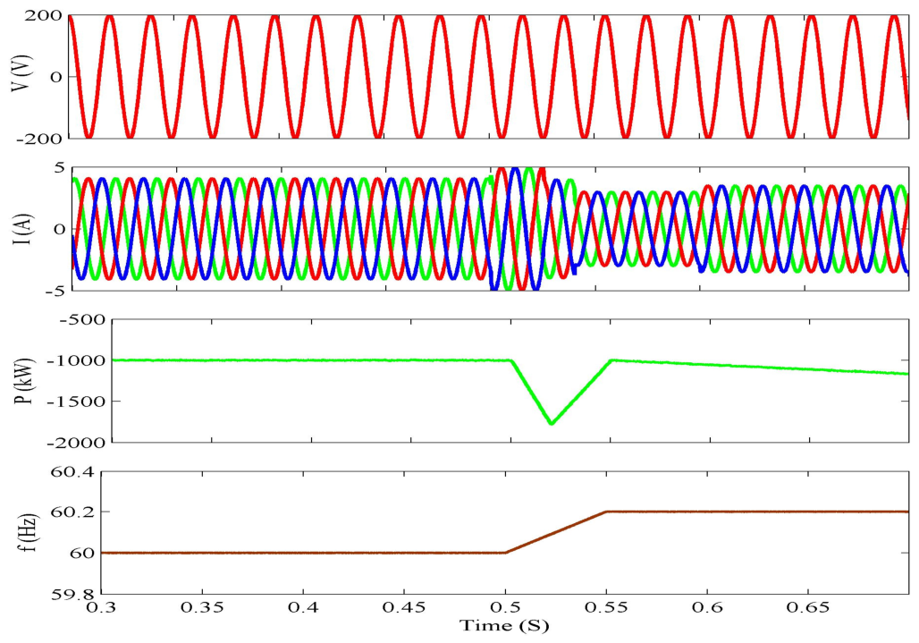
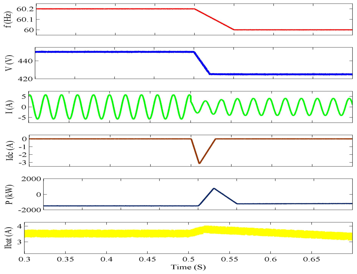
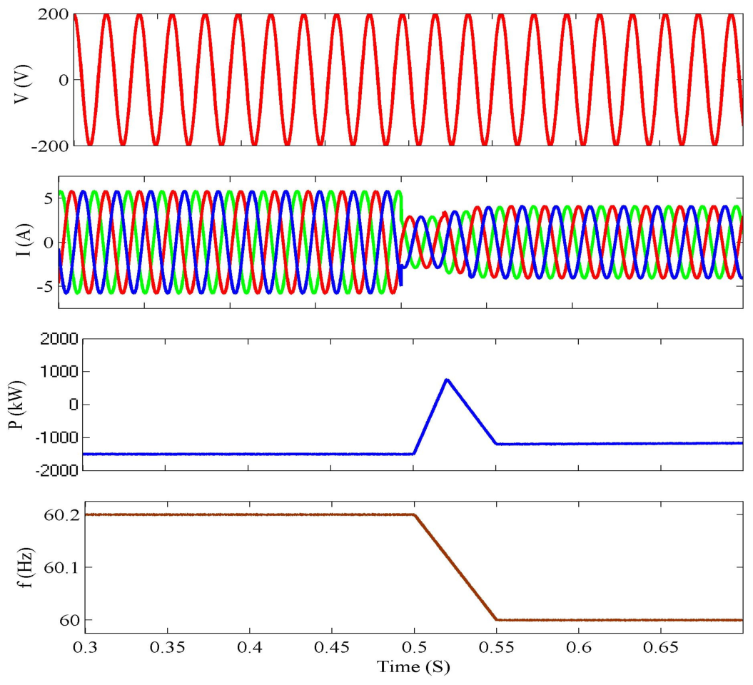
1. Introduction
As the global transition toward renewable energy accelerates, power systems face increasing challenges in maintaining frequency stability due to the declining presence of synchronous generators and the associated mechanical inertia. To address this issue, the concept of Grid-Forming and Grid-Following Virtual Inertia (GFL VI) has emerged as a critical solution. This paper presents a comprehensive study on the implementation of GFL VI in Electric Vehicle Battery Chargers (EVBCs) using a novel control strategy [
1,
2]. The approach leverages a hybrid energy storage system (HESS) composed of a DC-link capacitor and a battery to emulate virtual inertia and provide full Vehicle-to-Grid (V2G) functionality, including long-term frequency support, voltage regulation through reactive power compensation, and harmonic current filtering [
3,
4]. A two-stage AC–DC converter topology is proposed, integrating a three-phase Voltage Source Inverter (VSI) and a Dual Active Bridge (DAB) resonant DC–DC converter to interface with the grid and the EV battery, respectively. The control architecture is modular, incorporating fast, medium, and slow dynamic controllers to manage different timescale requirements efficiently [
5,
6,
7]. Key innovations include an enhanced frequency estimation method using a phase-locked loop (PLL) with a low-pass filter (LPF) to minimize overshoot and improve transient response, and the strategic management of energy flow between the capacitor and battery to preserve battery life while ensuring rapid frequency response [
8,
9]. Most renewable energy systems are connected to the grid through inertialess power electronics converters, leading to a decrease in the overall system inertia and consequently to deviations of frequency beyond the acceptable range, resulting in undesirable load-shedding or even large-scale blackouts [
10].
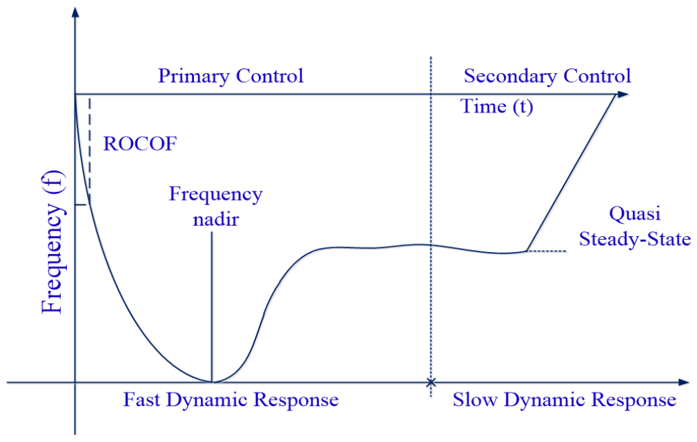
These frequency variations can be quantified by two parameters, the time derivative of the frequency, known as rate-of-change-of-frequency (ROCOF), and the minimum value of the frequency during the transient period, known as frequency nadir [
11,
12,
13,
14], which are shown in
Figure 1. To overcome this problem, researchers have proposed the concept of virtual inertia (VI) [
15] which consists of the integration of an energy storage system (ESS) into the grid to emulate the synchronous generator behavior [
16,
17] by grid-connected converters (GCCs), commonly called grid-forming converters (GFMs) [
17,
18,
19,
20]. However, since GCCs with GFM control strategies are controlled as a voltage source, the direct control of the AC voltage without an inner current control loop may lead to difficulties in dealing with voltage drop faults, generating over currents and stability problems, making these solutions challenging to integrate into distribution grids [
21].
The proposed control strategy is validated through both analytical modeling and simulation results, demonstrating its efficacy in delivering robust frequency and voltage support under grid disturbances. This work offers a scalable, firmware-based upgrade path for existing EVBCs, supporting their role as active participants in modern, flexible power systems.
Table 1 provides literature survey data on HESS technology.
In
Table 1, existing studies primarily focus on hybrid energy storage configurations, energy management strategies, and renewable energy integration. However, limited attention has been given to the coordinated implementation of virtual inertia, long-term frequency regulation, reactive power support, and harmonic compensation within a unified EV battery charger architecture. Furthermore, most existing approaches either rely solely on DC-link capacitors for inertia emulation or employ hybrid energy storage systems without integrating comprehensive V2G ancillary services. To address these gaps, this work proposes a dual-converter EV battery charger equipped with a hybrid energy storage system and a multi-timescale control framework capable of delivering full V2G functionality while improving frequency stability, voltage support, and power quality.
The structure of the paper is organized into several key sections. It begins with the Abstract, providing a concise summary of the objectives, methodology, and findings of the study. The Introduction follows, highlighting the challenges posed by reduced system inertia due to renewable energy integration and introducing the concept of virtual inertia using EV battery chargers with a hybrid energy storage system (HESS). A literature review presents related work on HESS technologies, control strategies, and applications, summarizing gaps addressed by the proposed method. The Fundamentals of GFL Virtual Inertia section explains the theoretical basis, mathematical modeling, and limitations of conventional GFL VI implementations. The Proposed Control Strategy section outlines the two-stage power converter architecture and details the multi-timescale control scheme, dividing it into fast (AC current), medium (DC-link voltage, VI, battery current), and slow (power and droop) response controllers, along with enhanced PLL-based frequency estimation. The Simulation Results section validates the effectiveness of the proposed system through tests on harmonic compensation, virtual inertia performance, HESS dynamic response, and voltage support under different grid events. Finally, the Conclusion summarizes the benefits of the proposed strategy, including improved frequency stability, better harmonic performance, and enhanced suitability for future V2G applications, supported by a brief comparison with existing works and a comprehensive References section.
The main contribution of the paper is the development of a smart control strategy for Electric Vehicle Battery Chargers (EVBCs) that helps support the power grid by providing virtual inertia, frequency regulation, voltage support, and harmonic compensation. This is achieved using a hybrid energy storage system (HESS) that combines a fast-responding DC-link capacitor and a slower battery, allowing for efficient energy management. The paper introduces a two-stage converter system and designs a multi-level control scheme with fast, medium, and slow response times. It also improves frequency estimation by using a phase-locked loop (PLL) with a low-pass filter to reduce overshoot. Simulation results show that the proposed system can handle sudden changes in grid frequency, reduce power distortion, and support voltage during sags, making it a practical and scalable solution for enhancing the stability and flexibility of modern power grids through existing EV infrastructure.
Research Gap and Motivation
Despite significant advances in virtual inertia control, hybrid energy storage systems, and Vehicle-to-Grid technologies, several important challenges remain unresolved. Existing virtual inertia implementations commonly rely on either DC-link capacitors or battery energy storage systems alone. While DC-link capacitors can provide fast inertial response, their limited energy capacity restricts their ability to sustain grid-support services for extended periods. Conversely, battery-based inertia support can supply larger amounts of energy but may accelerate battery degradation due to frequent charge–discharge cycles associated with rapid frequency disturbances. Furthermore, most reported studies focus on a single ancillary service, such as virtual inertia or frequency regulation, without considering the simultaneous provision of reactive power support and harmonic compensation. In addition, coordinated energy management strategies capable of effectively distributing fast and slow dynamic responses among different storage elements remain limited.
Therefore, there exists a need for an integrated EV battery charger architecture that can simultaneously provide fast virtual inertia support, long-term frequency regulation, reactive power compensation, and harmonic mitigation while minimizing battery stress and improving overall grid-support capability. To address these challenges, this work proposes a hybrid energy storage-based EV battery charger employing a coordinated multi-timescale control framework in which the DC-link capacitor supplies rapid transient support and the battery delivers sustained energy support. The proposed approach enables comprehensive V2G functionality while enhancing grid stability, power quality, and energy management performance.
The main contributions of this work are summarized as follows:
Development of a dual-converter EV battery charger architecture incorporating a hybrid energy storage system composed of a DC-link capacitor and battery.
Design of a multi-timescale control framework that decouples fast virtual inertia support from long-term frequency regulation.
Implementation of coordinated active and reactive power control for simultaneous frequency support and voltage regulation.
Integration of harmonic compensation functionality to improve power quality at the grid interface.
Validation of the proposed strategy through comprehensive simulation studies under frequency disturbances, voltage variations, and harmonic conditions.
2. Fundamentals of GFL VI
The GFL VI concept is based on the dynamics of the swing equation which is given by (1):
where
—derivative of time;
—frequency deviation;
—power difference for generated power and load power;
H—inertia constant.
It can be easily followed that for a certain variation in power, inertia reduction in power systems leads to higher ROCOF and higher peak deviation of frequency. Hence, the concept of GLF VI consists of the integration of ESS for adding extra power to the system according to (2):
where
is the instantaneous frequency of the system.
Then, substituting (3) into (2), the frequency dynamics of the system including the VI are given by the following:
This way, the effective inertia constant is increased to , increasing the frequency stability.
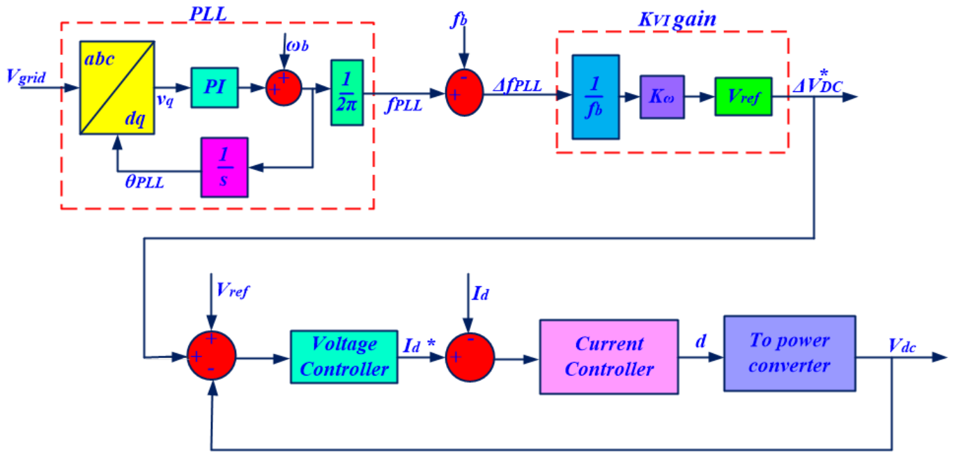
The implementation of the GFL VI approach in a VSI was introduced according to the functional diagram presented in
Figure 2. Note that the GFL VI approach relates the frequency deviation
, measured by PLL, with a voltage deviation
, in the DC-link voltage, according to a gain
. Moreover, the control strategy considers the well-known voltage and current control loops as presented in the block diagram of
Figure 3.
Hence, a frequency deviation,
, generates a fast response of power through releasing/storing the energy in the DC-link capacitor CDC according to a “virtual inertia” (Hv) coefficient given by (5):
where
The gain
in (5) is designed for the allowed maximum frequency deviation
and a maximum voltage variation
according to (7), where
and
are the base grid frequency and the rated DC bus voltage, respectively:
Then, the dynamic response of DC-link voltage is related to the fast power response
(inertia response) according to the following:
4. Proposed Control Strategy
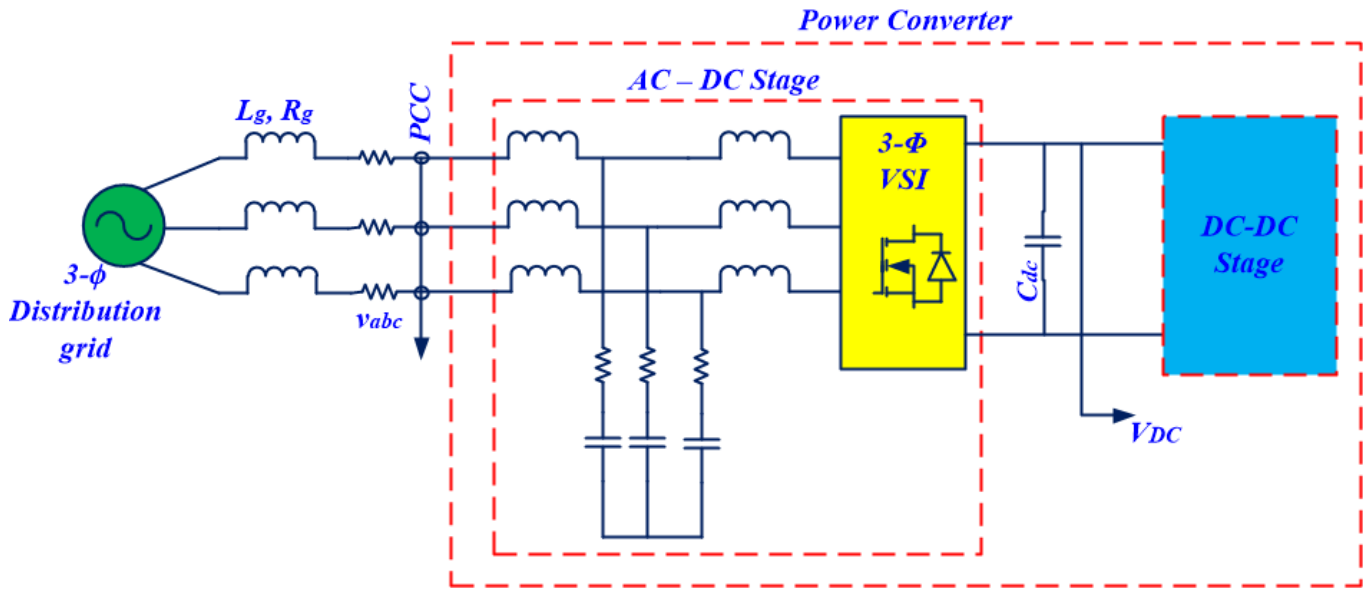
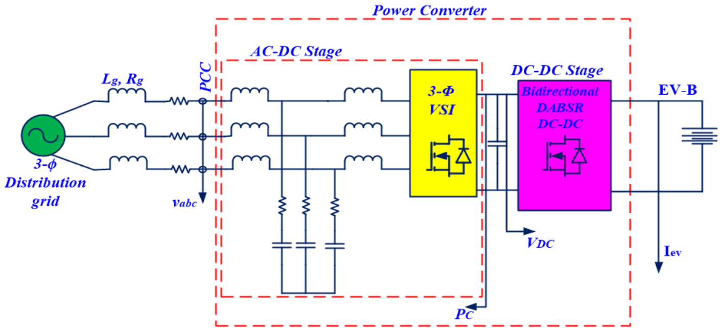
The block diagram of the proposed control strategy and the scheme of the power stage are shown in
Figure 5. Note that a two-stage AC–DC topology is adopted which is composed of a three-phase VSI to interface with the grid, and a Ddual Active Bridge series resonant DC–DC converter to interface with the EV battery.
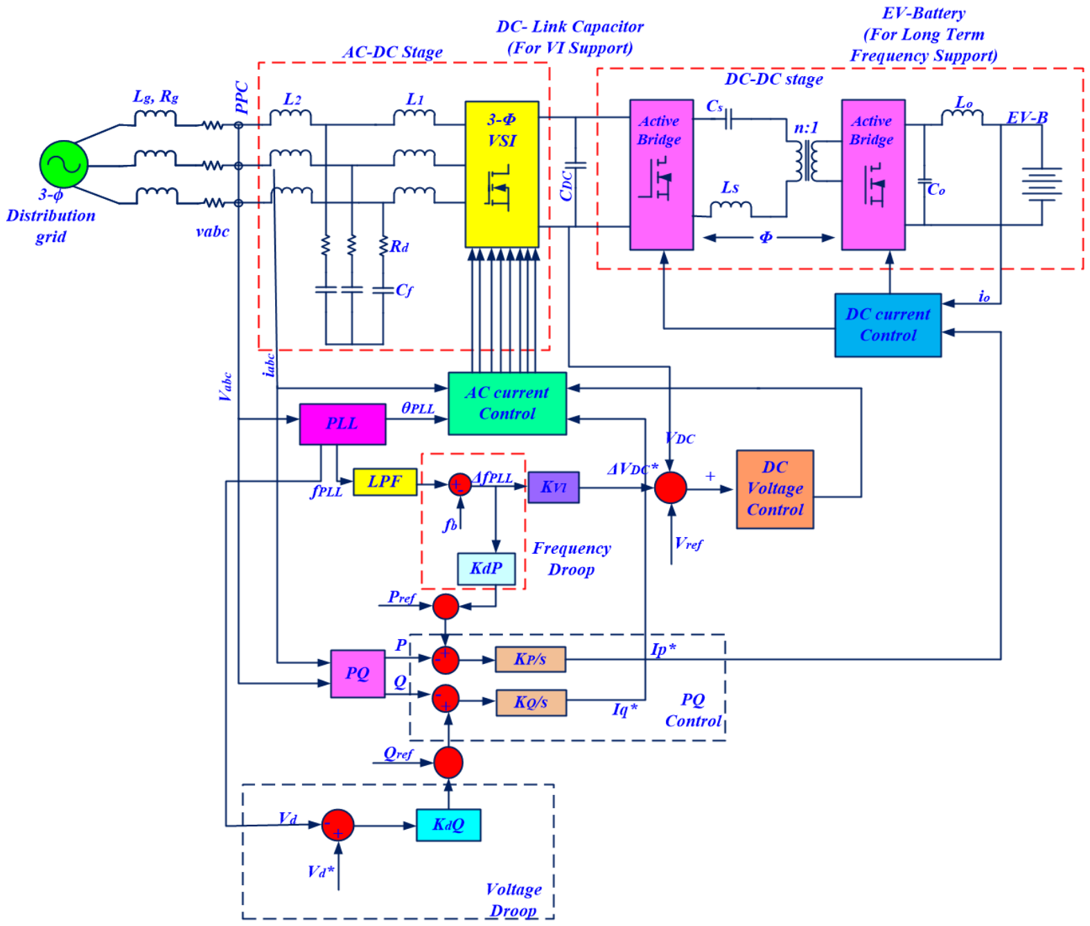
In the proposed control strategy, different V2G functionalities are implemented through managing a HESS as shown in
Figure 6. For this purpose, six controllers are designed: the AC current controller, the DC bus voltage controller, the DC current controller, the VI controller, the PQ controllers (active power P and reactive power Q controllers), and the droop controllers to compensate for frequency and voltage variations. In addition, a computational block to calculate active and reactive power (PQ block), a PLL, and transformation blocks complete the control strategy. The management of HESS allows to decouple the dynamics responses of active power as shown in
Figure 6. Note that in front of a frequency variation increment
, the power delivered by the converter
is given by the following:
where
and
are active powers supplied by the DC-link capacitors and the EV battery, respectively. The power
has a faster dynamic response compared to
, and it is intended for VI support unlike
which is focused on long-term frequency support. For simplicity, no power losses are considered. Moreover, in the proposed control strategy, the controllers are classified according to timescale as fast, medium, and slow response. A fast response is required for the inner AC current controller on the AC–DC stage, with a timescale of around a few milliseconds. The medium response is related to DC-link voltage, VI, and DC current control, with a timescale of several milliseconds. Finally, the slow response corresponds to the PQ and droop controller with a timescale of several seconds. Since special care must be taken in choosing the bandwidth of medium response controllers to ensure system stability, the transfer functions and controller design are explained as follows.
4.1. Stability Analysis of the Proposed Control Strategy
The proposed EVBC-HESS controller adopts a hierarchical multi-timescale control architecture in which the individual control loops operate at different bandwidths. Such a design is widely used in power electronic systems to ensure dynamic decoupling and stable operation.
The AC current controller is designed as the fastest loop with a bandwidth of approximately 800 Hz, enabling rapid current tracking and disturbance rejection. The PLL and DC-link voltage controller operate at intermediate bandwidths of approximately 60 Hz and 30 Hz, respectively, while the battery current controller and active/reactive power controllers operate at slower timescales ranging from 5 Hz to 1 Hz. This bandwidth hierarchy ensures that the inner loops reach steady-state conditions before the outer loops respond, thereby minimizing dynamic interactions among controllers.
The ratio between adjacent control bandwidths is maintained above two, providing sufficient dynamic separation and reducing the possibility of control-loop coupling. In addition, the low-pass filter integrated into the frequency estimation mechanism suppresses high-frequency measurement noise and mitigates transient overshoot, thereby improving system damping characteristics.
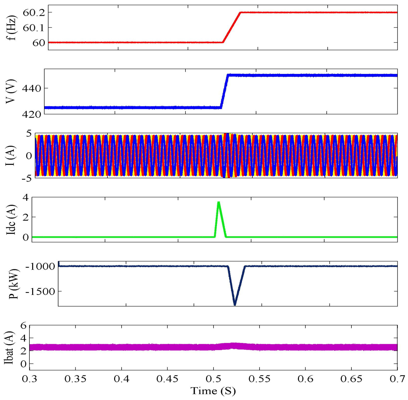
The stability of the proposed framework is further verified through simulation studies under frequency disturbances of ±0.2 Hz, voltage variations of 17 V, and ROCOF conditions up to 3 Hz/s. In all cases, the system exhibits stable responses without sustained oscillations, divergence, or controller saturation. The DC-link voltage, battery current, and active/reactive power outputs remain within acceptable operating limits throughout the disturbances, confirming the effectiveness of the proposed control architecture.
Therefore, the combination of bandwidth separation, hierarchical control design, and coordinated energy management contributes to the stable operation of the proposed EVBC-HESS under a wide range of operating conditions.
4.2. Fast Response Control: The AC Current Controller
For AC current, proportional + resonant controllers in the stationary
αβ frame are adopted. The TF from VSI voltage to AC current is given by (12) where
are respectively the VSI side inductance, grid side inductance, filter capacitance, and damping resistance [
29]:
The transfer function of the PR controllers with selective harmonic GPR(s) is defined in (13), where
is the proportional gain,
(
j = 13,57,9) are the gains for resonant components, and the term
ξ is the damping factor which defines the bandwidth of the resonant components and the gain at each resonance frequency:
4.3. Medium Response Control
4.3.1. DC-Link Voltage Controller
The DC-link voltage controller is designed to provide the reference
for the AC current controller according to the following equation:
where
m is the modulation index.
Moreover, since the reference for the DC-link voltage is provided by the VI controller, the dynamics of the VI controller should be slower to ensure the system stability.
4.3.2. Enhanced GFL VI Controller
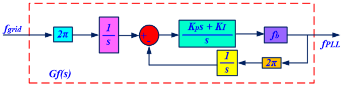
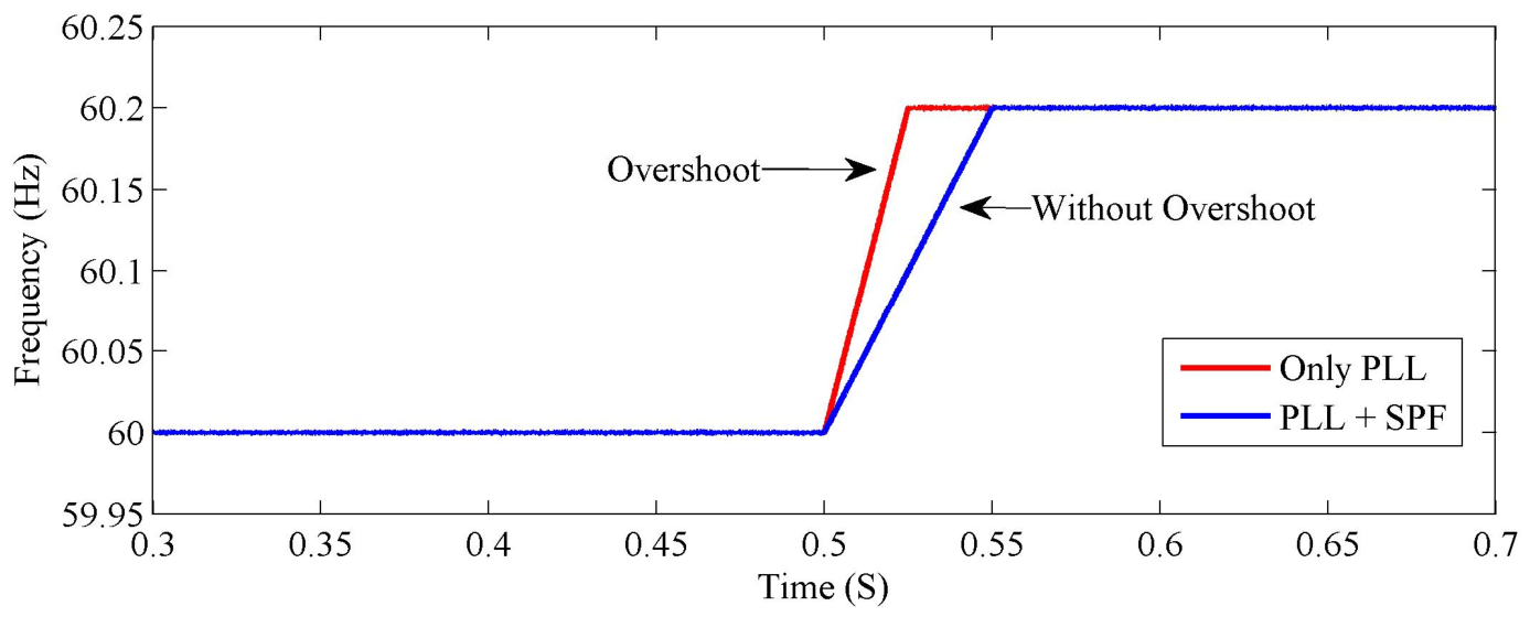
As explained in the discussion on limitations of GFL VI, the traditional GFL VI approach generates an overshoot of 7% in the frequency estimation by the PLL. To reduce the overshoot, the estimated frequency
is filtered by a first-order low-pass filter (LPF), as shown in
Figure 6. The LPF must be tuned with a cutoff frequency lower than the DC-link voltage dynamic response to ensure stability. To evaluate the effectiveness on the resulting overshoot, the PLL response was evaluated with three different configurations: a PLL tuned at 10 Hz bandwidth without LPF, a PLL tuned at 60 Hz bandwidth without LPF, and a PLL tuned at 60 Hz bandwidth with an LPF tuned at 10 Hz. The PLL with LPF overshoot value can be obtained by evaluating the PLL TF
, given by (9), including the LPF TF, leading to the following:
With cutoff frequency of for the LPF, following the procedure-detailed frequency measurement from PLL, a maximum ROCOF of 1.004 Hz/s is calculated. Hence, the overshoot in the estimated frequency has been considerably decreased, which leads lower transient peak deviation for both DC bus voltage and supplied power for VI.
4.3.3. Battery Current Controller
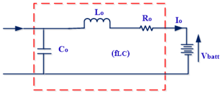
The equivalent circuit to control battery current
Io is shown in
Figure 7 and
Figure 8, where
are the inductance and capacitance for the DC filter and
is the inductor series resistance, whereas the averaged current source
is given by the following:
In (16), φ is the phase-shift angle, n is the turns ratio of HF transformer,
is the DC-link voltage, Z is the tank impedance, and F is the ratio between the switching frequency
and the resonance frequency
. The parameters Z, F, and
are defined in (17), where
and
are the inductance and capacitance of the resonant circuit:
Then, according to
Figure 7, the simplified TF for battery current
is given by the following equation:
where
is the cutoff frequency of the
,
filter.
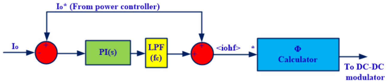
The block diagram of the proposed DC current controller is shown in
Figure 8. The LPF is tuned at
considering two decades lower than
to attenuate the resonance peak of
. With this consideration, the loop-gain TF
can be approximated according to (19), where
is considered as unity since
. Then, the zero
is tuned to eliminate the pole. Thus, the closed-loop TF
is given by (20):
4.3.4. Slow Response Controller
Instantaneous values of active power
p and reactive power
q are computed in the synchronous dq frame according to the following equations:
Since
is tracked by PLL synchronization,
and
, where
Vm is the amplitude of grid voltages. Therefore, TFs for
p and
q are given by the following:
Then, integral controllers with gains
Kp,
Kq are adopted from
Figure 5 and the closed-loop TFs
,
are given by the following:
Finally, droop controllers are tuned through gains
KdP and
KdQ, according to the following equations:
5. Validation of the Control Strategy
To validate the proposed control strategy, a MATLAB 2026a simulation is developed based on the parameters listed in
Table 2. For this
is limited to ensure the limited modulation, whereas the DC-link capacitance is sized considering the maximum allowed extra power
for VI support. Therefore,
, given by (8), must be limited to
, according to the following equation:
Then, from (6), (7), and (27), the maximum allowable DC capacitance is calculated by the following:
Since ROCOF
max is an a priori known value defined by grid codes, the gain
Kω, given by (7), is calculated as
Kω = 17.65 from parameters of
Table 2. Then, replacing values in (28),
CDC ≤ 3.13 mF is calculated. With this consideration,
CDC = 2.9 mF is adopted. Then, according to (5) and (6), an inertia of
HV ≈ 1.85 is obtained; thus, the converter can provide VI in front of frequency variations up to 3 Hz/s without exceeding its limits. On the other side, according to constraints in the proposed control strategy, the chosen controller’s bandwidths are listed in
Table 3.
Table 3.
Bandwidths for the controller.
Table 3.
Bandwidths for the controller.
| Fast | Medium | Slow |
|---|
| AC Current | PLL | Bus DC | Frequency LPF | Battery Current | P & Q |
| 800 Hz | 60 Hz | 30 Hz | 10 Hz | 5 Hz | 1 Hz |
Table 4.
Controller gains of the EVBC.
Table 4.
Controller gains of the EVBC.
| Controller | Gains |
|---|
| AC Current | |
| Battery Current | |
| PLL | |
| DC-Link Voltage | |
| Inertia | |
| Droop | |
| P—Q Controller | |
The PLL, DC-link voltage, and AC current controller parameters are tuned following the methodology of a grid-connected converter. The battery current and P&Q controllers’ parameters are calculated according the first-order systems given by (20) and (24), respectively, and the desired bandwidth given in
Table 3. Finally, the droop gains K
dP and K
dQ are calculated considering power deviations of
and
for frequency and voltage variations of 0.2 Hz and 17 V, respectively.
5.1. Stability and Robustness Considerations
The proposed control strategy employs a multi-timescale architecture in which the control loops are designed with well-separated bandwidths to reduce dynamic coupling and improve system stability. As shown in
Table 3, the AC current controller operates with the highest bandwidth (800 Hz), followed by the PLL (60 Hz), DC-link voltage controller (30 Hz), low-pass filter (10 Hz), battery current controller (5 Hz), and active/reactive power controllers (1 Hz). This hierarchical arrangement ensures that faster loops reach steady-state operation before slower loops respond, thereby minimizing adverse interactions among the controllers.
The stability of the proposed framework can be qualitatively justified through the adopted bandwidth separation. The ratio between adjacent control bandwidths exceeds a factor of two, which is commonly employed in cascaded power electronic control systems to guarantee stable operation and sufficient dynamic decoupling. In addition, the LPF integrated with the PLL reduces frequency estimation overshoot and prevents oscillatory responses during transient grid events.
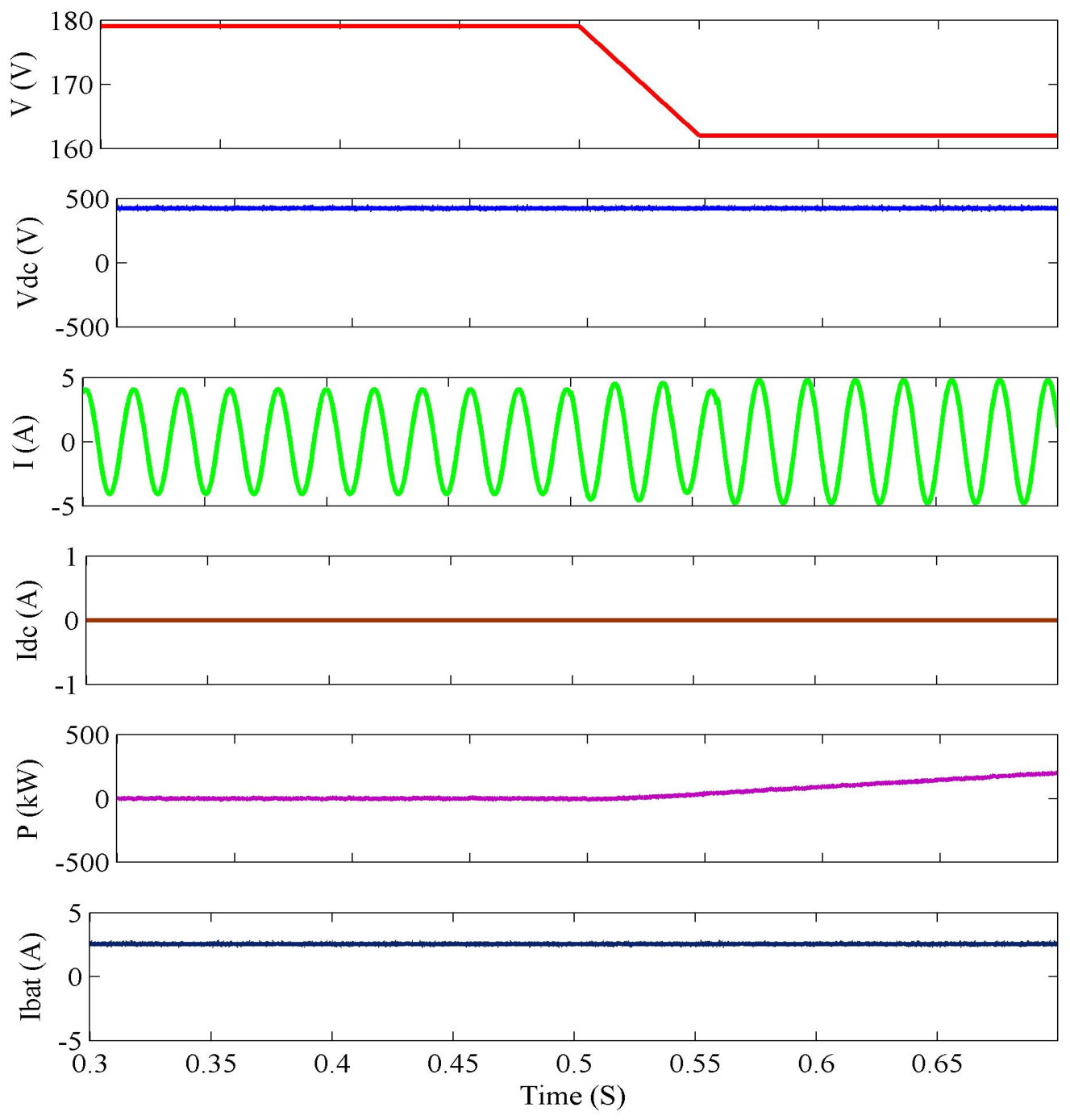
To assess robustness, the proposed system was subjected to several operating disturbances, including frequency variations of ±0.2 Hz, voltage amplitude reductions of 17 V, and ROCOF conditions up to 3 Hz/s. Under all tested conditions, the system maintained stable operation without sustained oscillations, controller saturation, or instability. The DC-link voltage remained within its designed operating range, the battery current remained properly regulated, and the active/reactive power support functions operated as intended.
These results indicate that the proposed multi-timescale control framework possesses satisfactory robustness against practical grid disturbances and parameter variations. Future work will focus on developing a detailed small-signal state-space model and performing eigenvalue, gain-margin, and phase-margin analyses to further quantify the stability characteristics of the proposed EVBC-HESS.
5.2. Dynamic Reactive Power Support Performance
To further evaluate the effectiveness of the proposed control strategy, a reactive power reference variation test was conducted. In this scenario, the reactive power reference was changed from 0 VAR to +400 VAR and subsequently returned to 0 VAR while the active power support and virtual inertia functions remained operational.
The results show that the reactive power controller successfully tracks the commanded reference with a fast transient response and negligible steady-state error. During the transition, the active power support function remained unaffected, demonstrating effective decoupling between active and reactive power control loops. In addition, the DC-link voltage remained within its operating limits and the battery current exhibited minimal variation, indicating that the reactive power compensation function does not impose significant additional stress on the energy storage system.
These observations confirm that the proposed EVBC-HESS architecture can reliably provide dynamic reactive power support while simultaneously maintaining frequency support and virtual inertia services. Therefore, the controller is suitable for practical grid-support applications where reactive power requirements may vary continuously due to changing load and network conditions.
7. Conclusions
This paper presented an integrated control strategy for Electric Vehicle Battery Chargers (EVBCs) equipped with a hybrid energy storage system (HESS) consisting of a DC-link capacitor and a lithium-ion battery. The proposed architecture combines a three-phase Voltage Source Inverter (VSI) and an isolated Dual Active Bridge (DAB) converter to provide comprehensive Vehicle-to-Grid (V2G) services, including virtual inertia emulation, long-term frequency regulation, reactive power support, and harmonic compensation.
The proposed multi-timescale control framework successfully decouples fast and slow grid-support functionalities by utilizing the DC-link capacitor for transient virtual inertia response and the battery for sustained frequency support. Simulation results demonstrated that the proposed system can effectively respond to frequency disturbances of ±0.2 Hz while maintaining stable operation. The virtual inertia controller delivered a transient support power of approximately 786 W with a response time of about 80 ms, while the equivalent virtual inertia constant achieved was approximately 1.85 s. Furthermore, the enhanced PLL-LPF frequency estimation method significantly reduced the ROCOF overshoot from approximately 7% to 0.4%, thereby improving dynamic stability and reducing transient stress on the converter system.
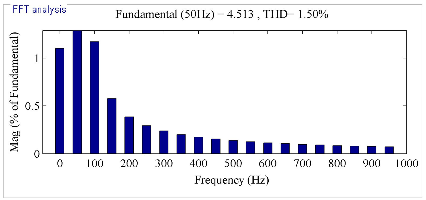
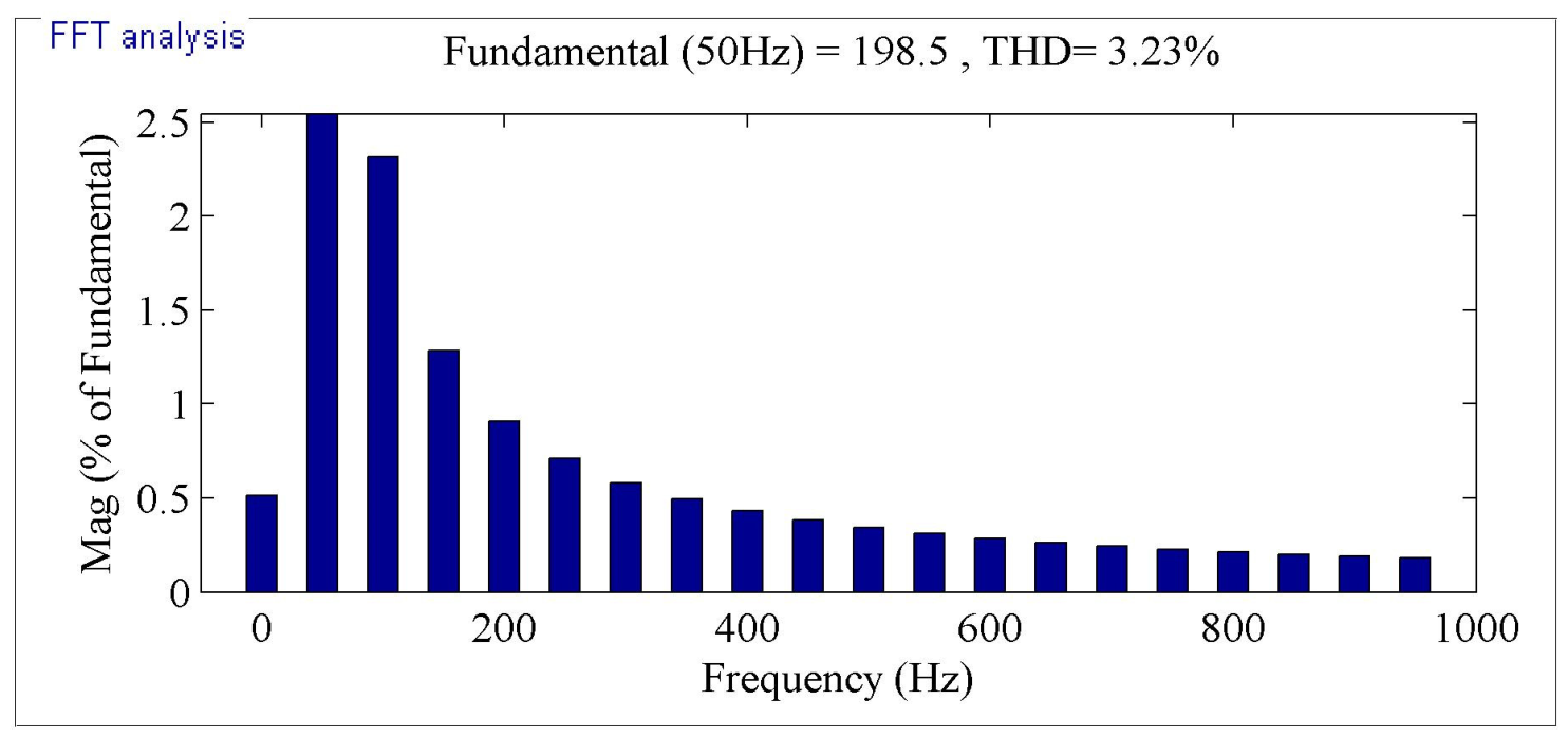
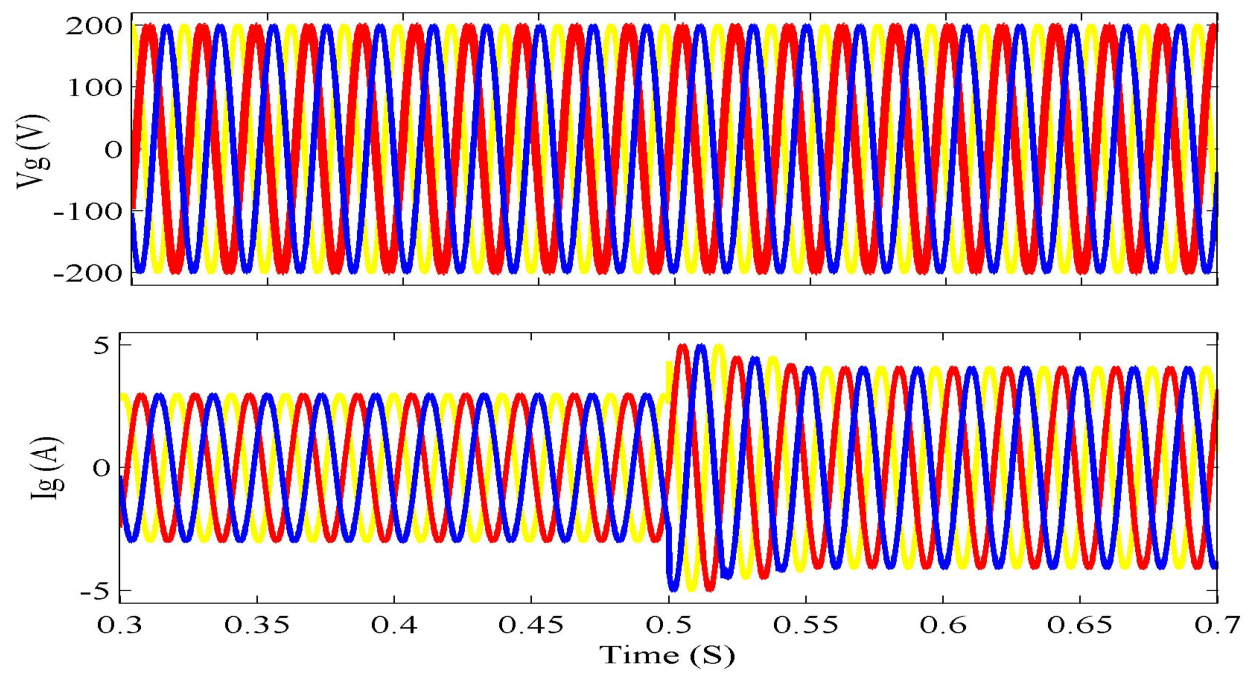
The harmonic compensation capability of the proposed controller was validated through FFT analysis. The grid current THD was reduced to 1.50%, while the compensated voltage THD was maintained at 3.23%, demonstrating compliance with power quality requirements and confirming the effectiveness of the selective harmonic compensation strategy. In addition, the voltage support functionality was verified under a grid voltage reduction of 17 V, where the controller supplied up to 400 VAR of reactive power support, increasing the grid current from 4.09 A to 4.81 A while maintaining an almost constant battery current of 2.56 A. These results confirm the ability of the HESS management strategy to support voltage regulation without imposing significant additional stress on the battery.
Compared with existing virtual inertia and V2G solutions, the proposed approach provides a unified framework capable of simultaneously delivering virtual inertia support, long-term frequency regulation, reactive power compensation, and harmonic mitigation using a single coordinated control architecture. The utilization of the DC-link capacitor for fast transient support reduces battery cycling stress and potentially contributes to longer battery lifetime. Furthermore, the proposed solution can be implemented as a firmware-level enhancement to existing EV charging infrastructure, facilitating cost-effective deployment in future smart grids with high renewable energy penetration. Future work will focus on experimental validation using a hardware prototype, real-time controller implementation, scalability assessment under large-scale EV aggregation scenarios, and the extension of the proposed framework to bidirectional wireless charging and Inductive Power Transfer (IPT)-based Vehicle-to-Grid systems.





 ,
,