1. Introduction
As the “stabilizers” and “high-capacity batteries” of modern power grids, pumped-storage power stations play a key role in peak shaving, valley filling, and ensuring the large-scale integration of renewable energy [
1,
2,
3]. However, the underground cavern groups constructed for pumped-storage power stations often feature complex geological structures and large excavation inclination angles. Traditional hard-rock tunnel boring machines are mostly designed for flat or mildly sloping tunnels. During bottom-up excavation in large-inclination shafts, the equipment is continuously subjected to the component of its own gravity, rendering it highly susceptible to slipping or falling accidents [
4,
5,
6].
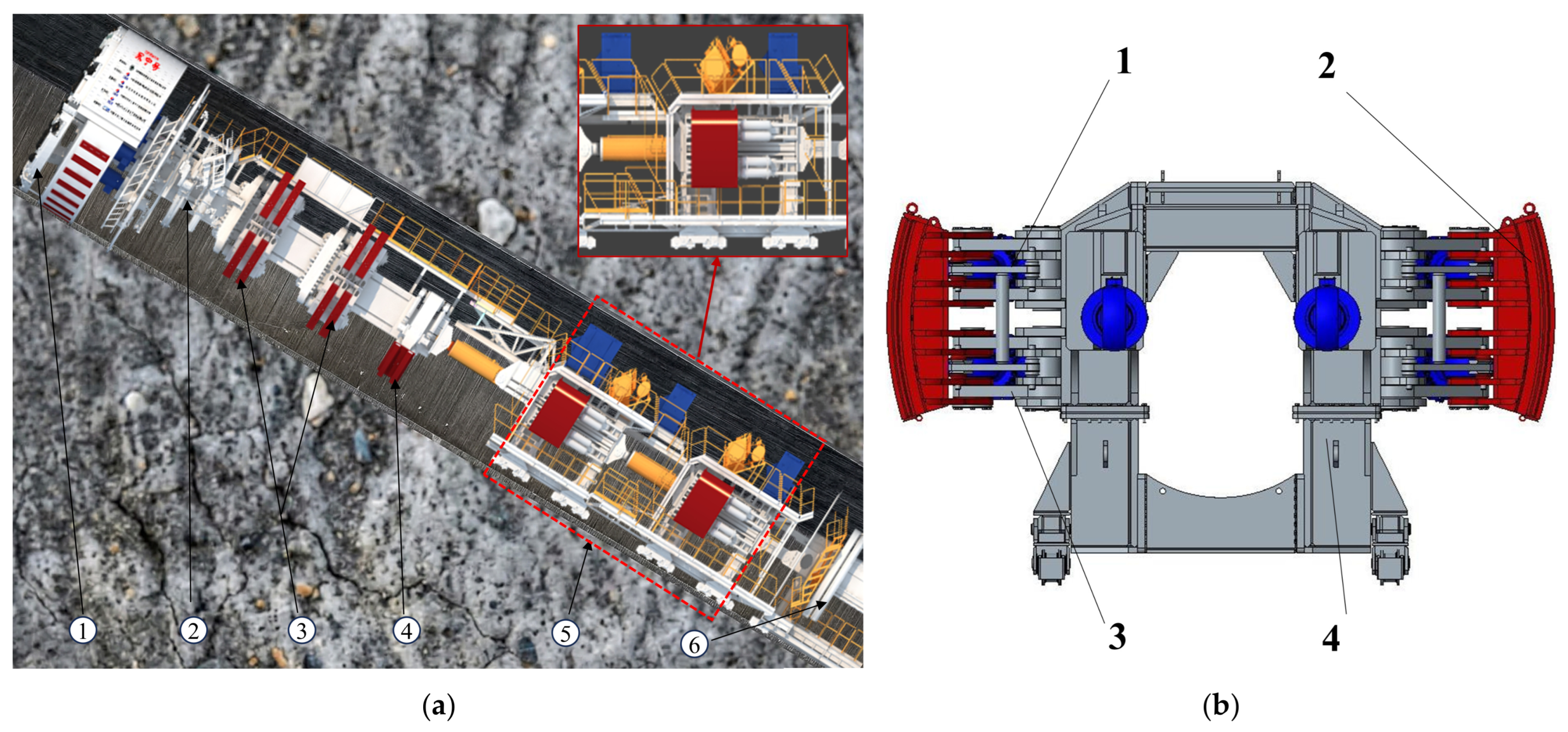
To address the challenges of large-inclination excavation, the Anti-Back-Slip support system has been widely introduced and serves as the core device ensuring the operational safety of inclined shaft TBMs [
7]. During the dynamic excavation and regripping process, the ABS support system must withstand axial eccentric loads and rock reaction forces. Furthermore, the posture and displacement synchronization accuracy of its hydraulic cylinders directly determine the overall safety, excavation efficiency, and support stability of the TBM [
8,
9]. Directional control valves or servo valves are extensively used for the precise control of hydraulic cylinders. The latest solutions for synchronizing cylinder operations utilize proportional valves coupled with the individual, continuous measurement of cylinder positions. However, inaccuracies in actuator synchronization still occur in practical applications. This is due, among other things, to the capacitance of the system (such as the supply lines) and the unstable operation of the actuator control valves. Furthermore, the unstable operation of the valves and the uneven operation of the actuators may be caused by the excitation of spool vibrations induced by external mechanical vibrations [
10]. Once the multiple hydraulic cylinders become desynchronized, it will cause uneven loading on the gripper shoes, physical distortion of the frame, and even the overturning and instability of the entire excavation system [
7]. Research on high-precision multi-cylinder synchronous control specifically dedicated to the ABS systems of inclined shaft TBMs remains scarce.
Existing research on the anti-falling and posture control of heavy-duty equipment mostly focuses on mine hoisting systems, coal mine hydraulic supports, or traditional lifting equipment. Giraud and Lonkwic designed mechanical safety catches for vertical shaft hoisting systems [
11,
12]. However, these purely mechanical structures are primarily passive trigger-locking devices. They cannot meet the real-time posture adjustment requirements during the continuous dynamic excavation process of TBMs. Zhang et al. thoroughly investigated the support control strategies of hydraulic supports in fully mechanized coal mining faces. However, their application scenarios are primarily static support, which does not involve dynamic multi-cylinder synergy while overcoming a significant gravitational component [
13,
14]. In addition, Zhang, Wang, et al. studied dual-cylinder and multi-cylinder synchronous lifting systems of large cranes, mostly adopting master-slave control or traditional PID algorithms [
15,
16]. Loren and Koren proposed three typical multi-cylinder synchronous control methods: master-slave synchronization, equal-status synchronization, and cross-coupling synchronization [
17,
18]. Among them, master-slave control exhibits certain hysteresis, and equal-status control lacks mutual feedback between individual loops. While the cross-coupling strategy provides accuracy and stability for dual-cylinder control, it becomes structurally complex when expanded to four cylinders. This complexity can lead to deteriorated synchronization accuracy and stability. Furthermore, due to the environment inside the TBM inclined shaft, traditional linear control algorithms often exhibit limitations such as insufficient robustness, weak disturbance-rejection stiffness, and a tendency for synchronization errors to diverge. These limitations render them inadequate for the safety requirements of the ABS system.
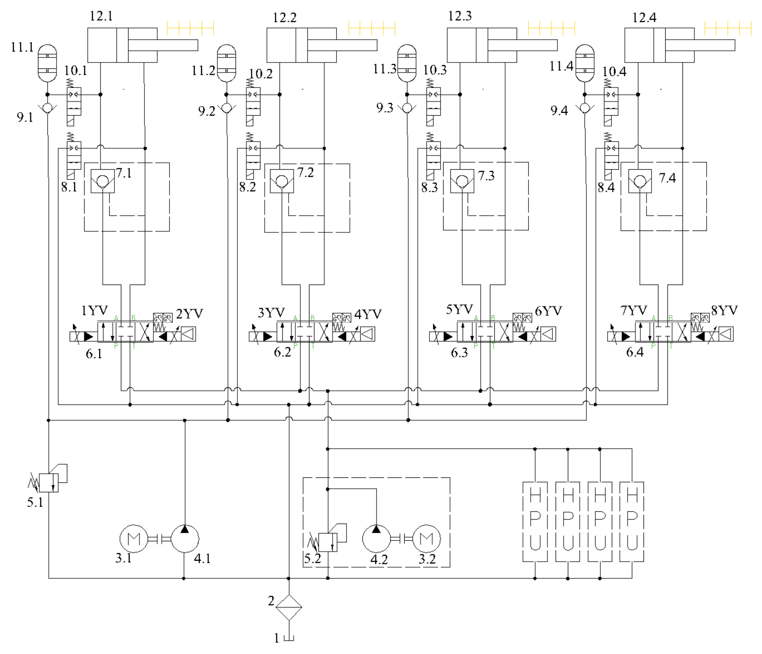
In summary, traditional anti-falling mechanisms and conventional synchronous control algorithms are no longer sufficient to meet the synergistic requirements of inclined shaft TBMs under complex working conditions. Therefore, taking the ABS hydraulic support system of inclined shaft TBMs as the research object, this paper designs a hydraulic control system for the ABS device and proposes an adjacent cross-coupling synergistic control strategy based on adaptive backstepping. This approach achieves synchronous control without requiring a precise mathematical model of the system. Relying on the AMESim-Simulink platform, co-simulations are conducted under both nominal and eccentric load conditions. The results indicate that under nominal conditions, the proposed algorithm exhibits asymptotic convergence at the mathematical level when tracking four different sets of desired signals. When subjected to sudden asymmetric dynamic eccentric loads of 1.0–2.0 times, the system prevents tracking divergence and limits the maximum multi-cylinder synchronization error to within 1.82 mm. The proposed method enhances the synchronization accuracy and stability of the ABS support system under complex working conditions.
3. Simulation Analysis
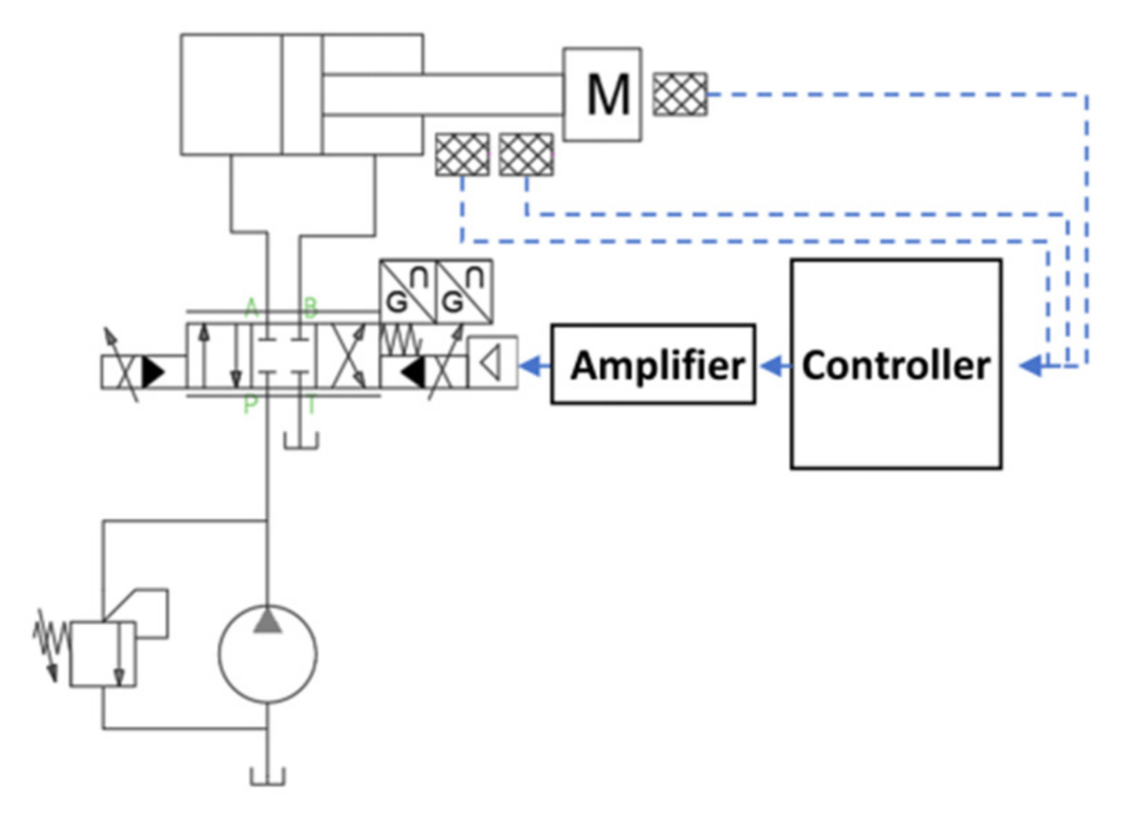
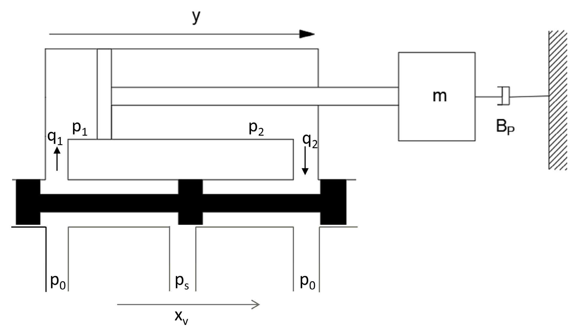
To verify the effectiveness of the designed adaptive backstepping controller, simulation validations are conducted within the MATLAB/Simulink R2018a environment. Given that the primary focus of this study is the synchronous control performance of the ABS support system, the system model established in Simcenter AMESim is appropriately simplified by neglecting secondary factors that are weakly correlated with the synchronous control characteristics. By retaining the critical mechanisms that dictate the system’s dynamic response and synchronization error, the computational efficiency and analytical targetedness of the simulation are improved, provided the model continues to accurately reflect the primary dynamic characteristics. Based on the hydraulic operational principles of the electro-hydraulic position servo system, the corresponding electro-hydraulic servo control model is established in the AMESim 2020.1 software.
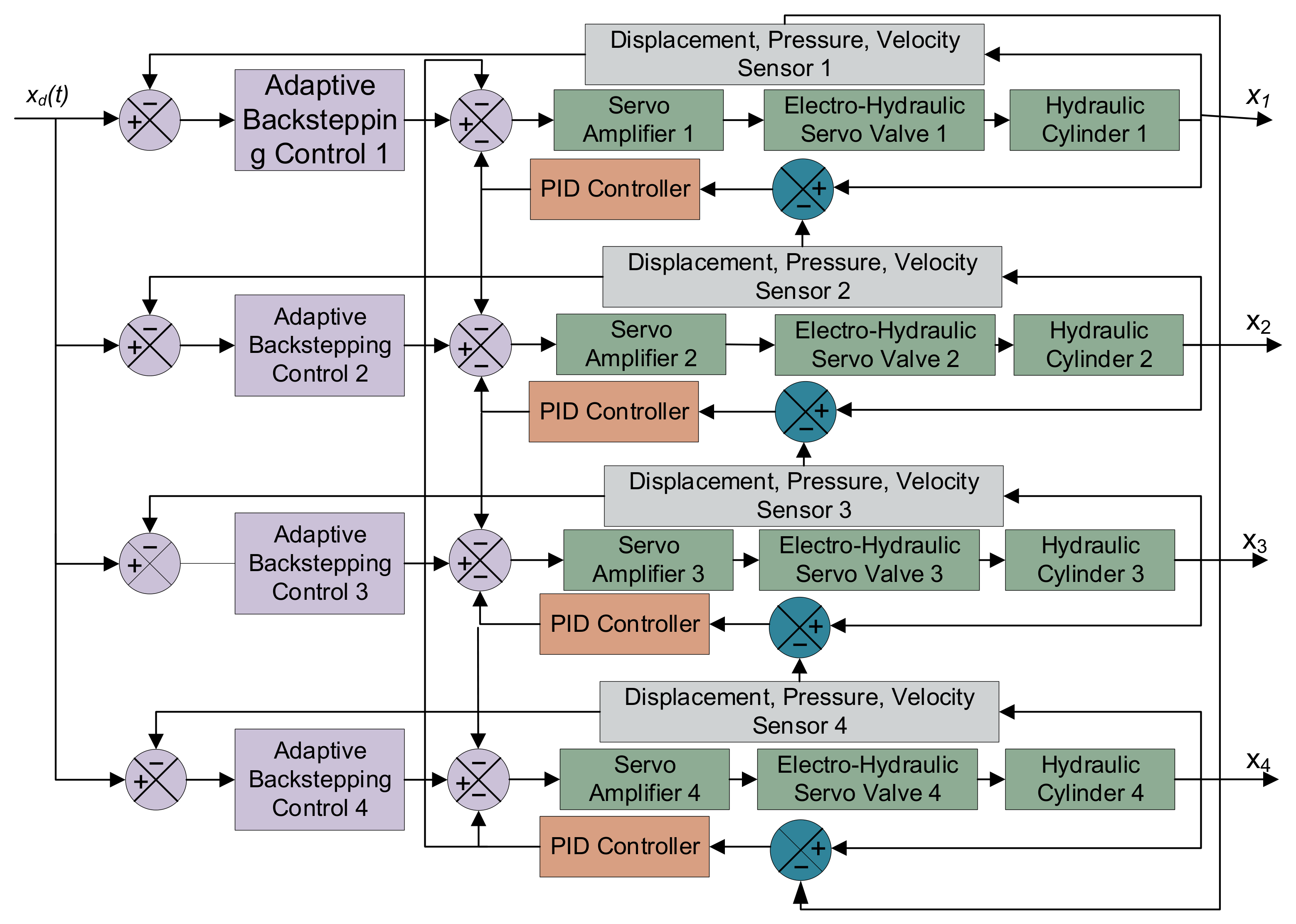
Adjacent cross-coupling synchronization builds upon equal-status synchronization by comparing the displacement difference between adjacent cylinders. After processing by the synchronous controller, these differential signals are fed back to individual loops, realizing high-precision control of each branch [
23,
24]. Adjacent cross-coupling effectively realizes the distributed synchronous control of the hydraulic system through a local error mutual-feedback mechanism among the actuators [
16]. Its principle is illustrated in
Figure 5, where each controller not only corrects the error of its own actuator but also outputs compensation signals to adjacent branches. This synergistic suppression of synchronization errors improves the synchronous performance of multiple actuators. Based on the operational principle of this strategy, the adaptive backstepping controller is selected as the single-cylinder displacement controller, while a PID controller serves as the synchronous compensator. The overall control strategy is depicted in
Figure 5.
In the AMESim simulation model, the physical plant is constructed utilizing components that include hydraulic cylinders, displacement sensors, pressure transducers, velocity sensors, hydraulic pumps, relief valves, proportional amplifiers, and servo valves. The principal parameters of these main components are detailed in
Table 1.
The adaptive backstepping controller is programmed utilizing the S-function in Simulink. The adaptive parameters are configured as follows: , . , Taking , for the system modeling, a sinusoidal signal is applied as the desired tracking reference in Simulink. It should be noted that the expression in the initial parameter vector is a constant value (approximately 581.16), representing the exact initial state at t = 0 with an initial phase shift of Through the empirical trial-and-error method, the controller gains of the adaptive backstepping algorithm, specifically k1, k2 and k3, are tuned to 13,000, 900, and 150, respectively. Concurrently, the proportional kp, integral ki, and derivative kd gains of the synchronous PID controller are set to 1000, 10, and 10, respectively.
In the practical engineering application of the ABS system on the “Luoning” TBM, the ambient temperature in the inclined shaft is approximately 30 °C, and the hydraulic system utilizes water cooling to maintain the fluid temperature at around 50 °C. This thermal management restricts severe variations in fluid viscosity and effective bulk modulus. To explicitly address the robustness of the system under relaxed modeling assumptions in practical heavy-duty engineering, it should be noted that additional unmodeled dynamics—including but not limited to variable fluid bulk modulus, temperature-induced variations, supply pressure ripples, and inherent valve dead-zone—are mathematically absorbed into the aforementioned lumped uncertainty term . To continuously compensate for these complex dynamic variations without requiring a precise mathematical model, the parameter vector is adapted online according to the proposed estimation law . To prevent numerical parameter drift and ensure physical feasibility, this adaptation is strictly confined within the defined lower bound and upper bound through a smooth projection mapping algorithm. Furthermore, the adaptation rate is dynamically governed by the adaptation gain matrix . While larger gains in can accelerate parameter convergence and theoretically enhance steady-state tracking precision, they can simultaneously induce severe transient peaking, high-frequency control chattering, and potential valve saturation. Therefore, the defined parameters , , and are carefully tuned to strike an optimal balance between rapid error convergence and the suppression of transient peaking.
It should be noted that the actual controller gains were determined through an empirical trial-and-error tuning process. In practical engineering applications, a balanced gain tuning guideline must be followed: the gains should be initially set to conservative lower values to prevent high-frequency noise amplification and actuator saturation. Subsequently, the gains should be incrementally increased while monitoring the dynamic response. This iterative heuristic process ensures an optimal trade-off between steady-state tracking precision and the physical constraints of the electro-hydraulic proportional valves.
3.1. Multi-Cylinder Trajectory Tracking Simulation
To comprehensively evaluate the performance of the proposed hydraulic cylinder synchronous control method, multiple desired trajectories are formulated as tracking test signals. These include a pure sinusoidal desired signal, as well as superpositions of the desired signal with sine, cosine, and white noise components, which are utilized to test the actual operational states and tracking errors of the hydraulic cylinders.
During the operational process, the piston rod of the hydraulic cylinder in the ABS support system is continuously subjected to the gravitational force of the gripper shoe. Furthermore, under the specific working conditions of the steeply inclined shaft, the magnitude of this gravitational component is inversely proportional to the extension length of the piston rod. Consequently, in the AMESim software, the sinusoidal load force applied to each hydraulic cylinder is defined as N, and the initial displacement of the hydraulic cylinder is set to 0.3 m. The integrated model is subsequently imported into the Simulink environment for co-simulation analysis.
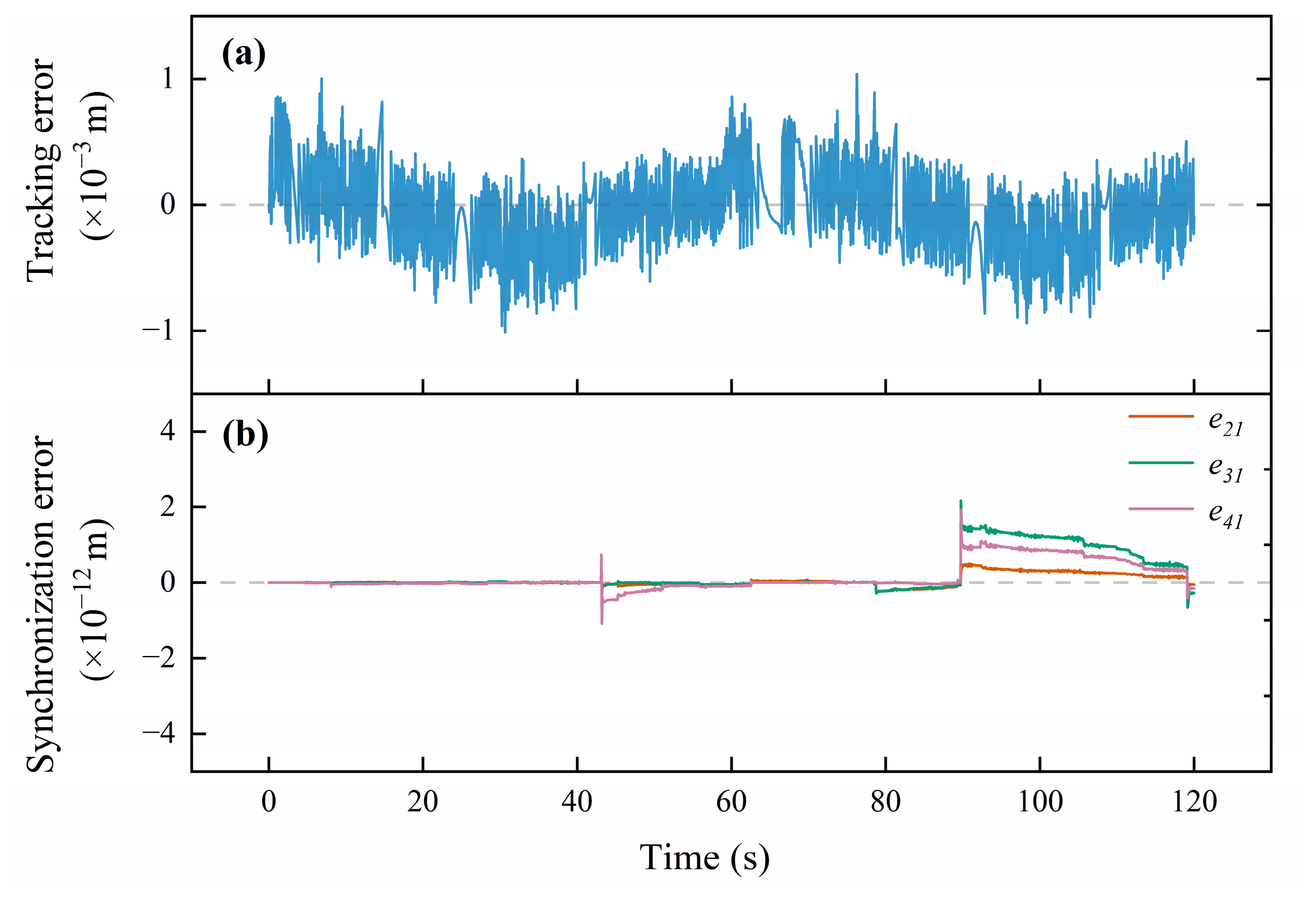
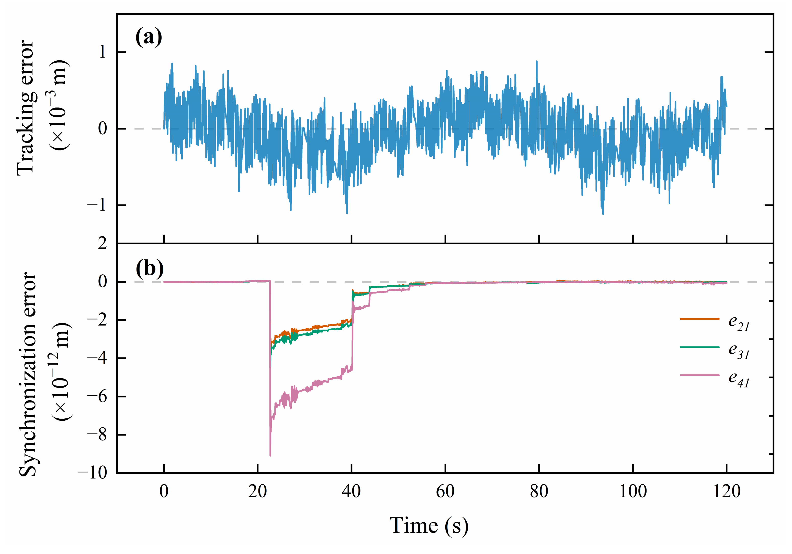
Owing to the highly effective control strategy, the actual trajectories macroscopically coincide with the desired trajectories almost perfectly. The tracking errors of the four hydraulic cylinders exhibit similar transient and steady-state behaviors, resulting in basically the same tracking trajectory for each cylinder. To prevent severe curve overlapping and to ensure visual clarity, this paper exclusively presents the tracking error plot of Cylinder 1 with respect to the desired signal. The synchronization accuracy of the system is further demonstrated through the inter-cylinder synchronization errors of Cylinders 2, 3, and 4 relative to Cylinder 1. The original desired tracking signal defined in Simulink is
m. The corresponding simulation results are illustrated in
Figure 6.
An analysis of
Figure 6 reveals that the designed adaptive adjacent cross-coupling control strategy provides stable steady-state control performance. Regarding trajectory tracking, as illustrated in
Figure 6a, the maximum position tracking error of the piston rod is kept within 1.03 mm, representing merely 0.68% of the given signal’s amplitude. The high-frequency micro-fluctuations observed in the error curve reflect the real-time, high-frequency dynamic compensation process executed by the adaptive backstepping controller to counteract the system’s inherent nonlinearities.
In terms of multi-cylinder synergistic synchronization, as shown in
Figure 6b, the maximum inter-cylinder synchronization error between Cylinders 2, 3, and 4 relative to Cylinder 1 is merely 2.2 × 10
−12 m. This picometer-level magnitude reflects the theoretical convergence limit of the proposed control algorithm within the double-precision numerical environment, rather than a macroscopic physical deviation. To address potential concerns regarding numerical stability and distinguish control performance from round-off errors, sensitivity checks were conducted across different solver configurations, as detailed in
Table 2.
As shown in
Table 2, the synchronization error is maintained across different solvers and under stricter tolerance settings. This confirms that the 10
−12 m precision is the mathematical consequence of the adaptive control law’s asymptotic convergence, rather than a numerical artifact or ill-conditioned round-off error. Furthermore, the transient steps in the synchronization error curve indicate that the adaptive parameter learning law can guide the error to reconverge when subjected to internal dynamic excitations.
A sine signal
is superimposed onto the original desired signal to simulate the motion requirements under multi-source excitations or complex working conditions in practical engineering, aiming to verify the control system’s comprehensive tracking capability for different frequency components. The simulation results are shown in
Figure 7.
Regarding trajectory tracking, as depicted in
Figure 7a, despite the complex composite frequency excitation, the maximum position tracking error of Cylinder 1 remains strictly constrained to 0.88 mm.
Figure 7b unveils the microscopic response mechanism of the adaptive cross-coupling strategy when dealing with internal dynamic excitations. Throughout the entire operational cycle, the maximum inter-cylinder synchronization error is 9.1 × 10
−12 m. At t = 22 s, the synchronization error exhibits a distinct transient plunge, followed by a step-like rapid convergence at t = 40 s. This phenomenon does not indicate system instability; rather, it occurs because the frequency superposition of the composite sinusoidal signal generates internal dynamic excitations and local acceleration extremums at specific moments. In the instant when such microscopic excitations induce displacement deviations, the adaptive parameter learning law performs high-frequency iterations to rapidly modify the control parameters. Simultaneously, the adjacent cross-coupling strategy intervenes, ensuring that all slave cylinders maintain highly consistent tracking even under extreme microscopic disturbances. This transient process fully demonstrates the parameter self-learning capability and the strong multi-cylinder coupling constraint capacity of the controller.
A cosine signal
is superimposed onto the original desired signal, causing the desired trajectory to exhibit more complex continuous multi-frequency variations. Consequently, this imposes higher requirements on the dynamic response bandwidth and disturbance-rejection capability of the control system. The simulation results are presented in
Figure 8.
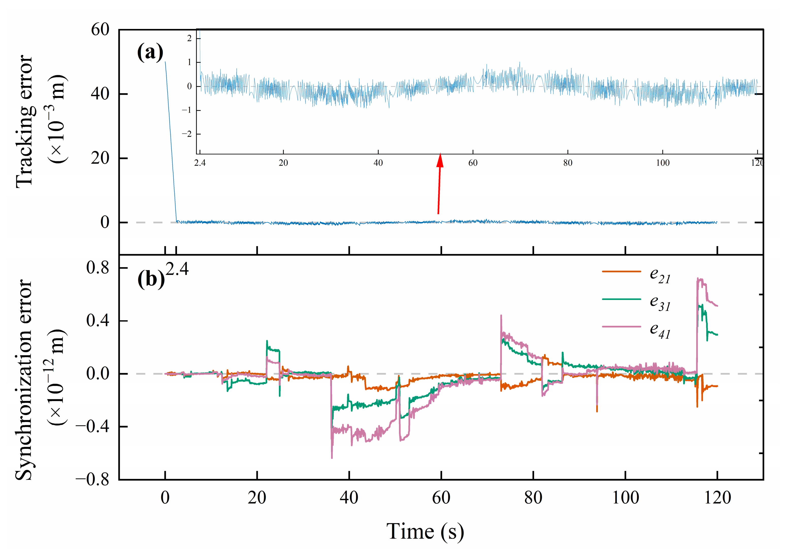
As shown in
Figure 8a, the tracking error stabilizes near the zero-scale line after an initial transient duration of 2.4 s. To explicitly illustrate the steady-state tracking precision, the inset in
Figure 8a locally magnifies the post-transient dynamic response. This specific magnification clearly demonstrates that the tracking error of Cylinder 1 consistently fluctuates around the zero-scale line, with its maximum value being only 1.02 mm despite the complex frequency reference signals. Regarding multi-cylinder synergistic synchronization, the results in
Figure 8b demonstrate that even under continuous dynamic alternating excitations of composite harmonics, the maximum inter-cylinder synchronization error of the adjacent cross-coupling system is merely 0.72 × 10
−12 m. The minute steps and dynamic fine-tuning processes exhibited in the error curve indicate that the adaptive parameter learning law possesses acute sensitivity when facing complex variable-frequency commands, achieving the synergistic consistency of the multi-cylinder system at a microscopic scale.
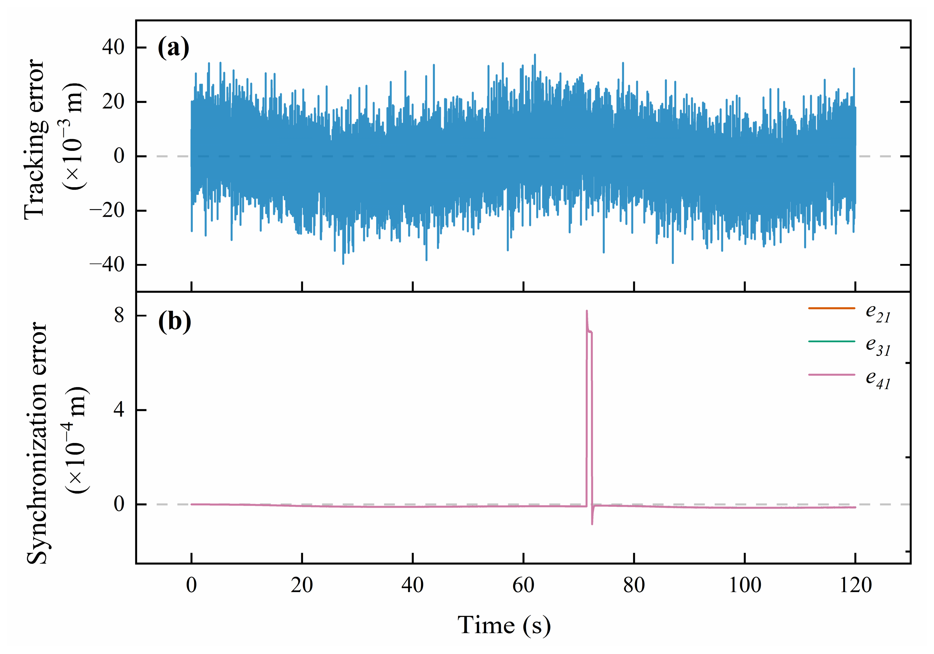
White noise with a power of 1 × 10
−6 is superimposed onto the original desired signal. This condition aims to simulate the random disturbances introduced by sensor measurement errors, external perturbations, and system uncertainties in actual engineering scenarios. The simulation results are shown in
Figure 9.
Regarding trajectory tracking, as depicted in
Figure 9a, under the influence of continuous system dynamics and external environments, the tracking error of Cylinder 1 exhibits a high-frequency broadband fluctuation. This continuous dynamic adjustment band authentically reflects the high-intensity, disturbance-rejection working state of the controller in a complex physical environment. As for multi-cylinder synchronization, shown in
Figure 9b, a transient sudden change with a peak value of 0.82 mm occurs in the cylinder synchronization error at t = 72 s. This represents an internal state mutation characteristic of nonlinear systems subjected to continuous broadband white noise excitation. When such unpredictable internal chaotic excitations occur, conventional controllers are highly prone to triggering system divergence and instability. However, the adaptive adjacent cross-coupling mechanism of this system responds within a short time, reallocating the control laws to converge the error back to a microscopic steady state approaching zero within 1 s. This process verifies the robustness of the control strategy in maintaining the mechanical synchronization of the platform under disturbance conditions.
3.2. Performance Analysis Against Eccentric Load Interference
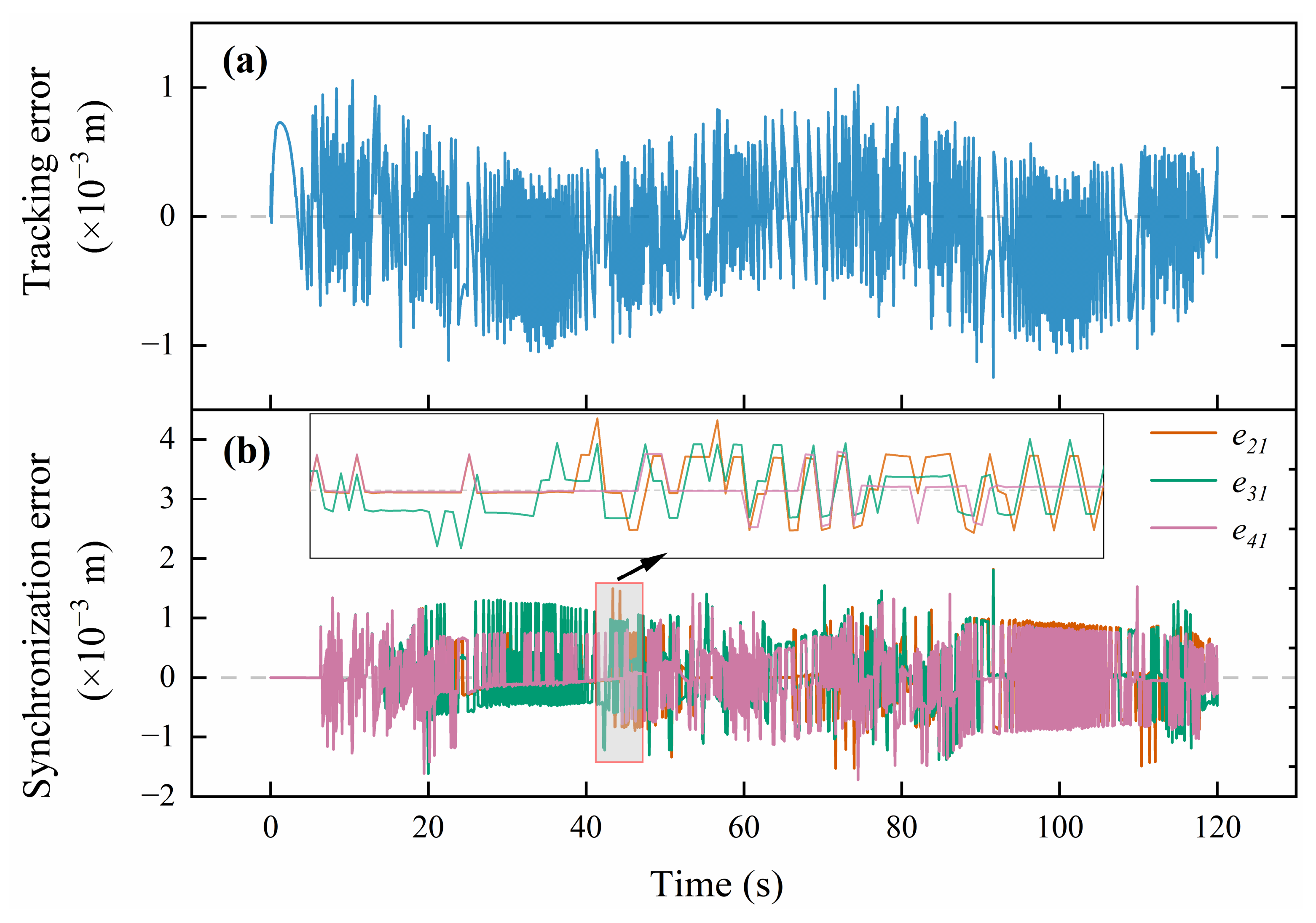
The preceding sections have detailed the response characteristics when tracking various desired signals under the adaptive backstepping control. Although the load variations during the extension of the hydraulic rod were considered, these were strictly limited to the ideal working conditions of the gripper shoes. To comprehensively verify the anti-interference performance against eccentric loading, a specific asymmetric load condition is introduced. The external disturbance force on Cylinders 1 and 3 remains unchanged, while a sinusoidal dynamic disturbance with a maximum amplitude of 150% (1.5×) of the original load is suddenly injected into Cylinders 2 and 4 at t = 20 s. This setup is designed to simulate the actual operational scenarios where the hydraulic cylinders of the ABS support system are subjected to differential external dynamic disturbances. The tracking results of each hydraulic cylinder against the original desired signal are illustrated in
Figure 10.
Regarding trajectory tracking, as illustrated in
Figure 10a, even under the dynamic eccentric load excitation, the maximum position tracking error of Cylinder 1 is merely 1.24 mm. The continuous error oscillation band depicts the dynamic compensation processes executed by the adaptive backstepping control law. This continuous compensation rejects the external sinusoidal disturbances and ensures macroscopic trajectory tracking accuracy. In terms of multi-cylinder synchronization and synergy, as shown in
Figure 10b, following the injection of the strong disturbance at t = 20 s, the disparity in the physical loads borne by the cylinders inevitably induces mechanical and hydraulic transient deformations, causing the synchronization error to jump to the millimeter scale. The synchronization error curves (e
21, e
31, and e
41) visually overlap on a macroscopic scale due to the high convergence precision of the controller. To demonstrate their dynamic differences, a locally magnified inset is added in
Figure 10b. This zoom-in view clearly captures the distinct transient adjustment processes and minute differential details of each cylinder. Ultimately, under the strong constraints of the adjacent cross-coupling strategy and the extreme rapid adjustment of the adaptive parameters, the maximum inter-cylinder synchronization error is strictly contained at 1.82 mm. This explicitly proves the controller’s synergistic capacity against eccentric loads, strong robustness, and high engineering application value.
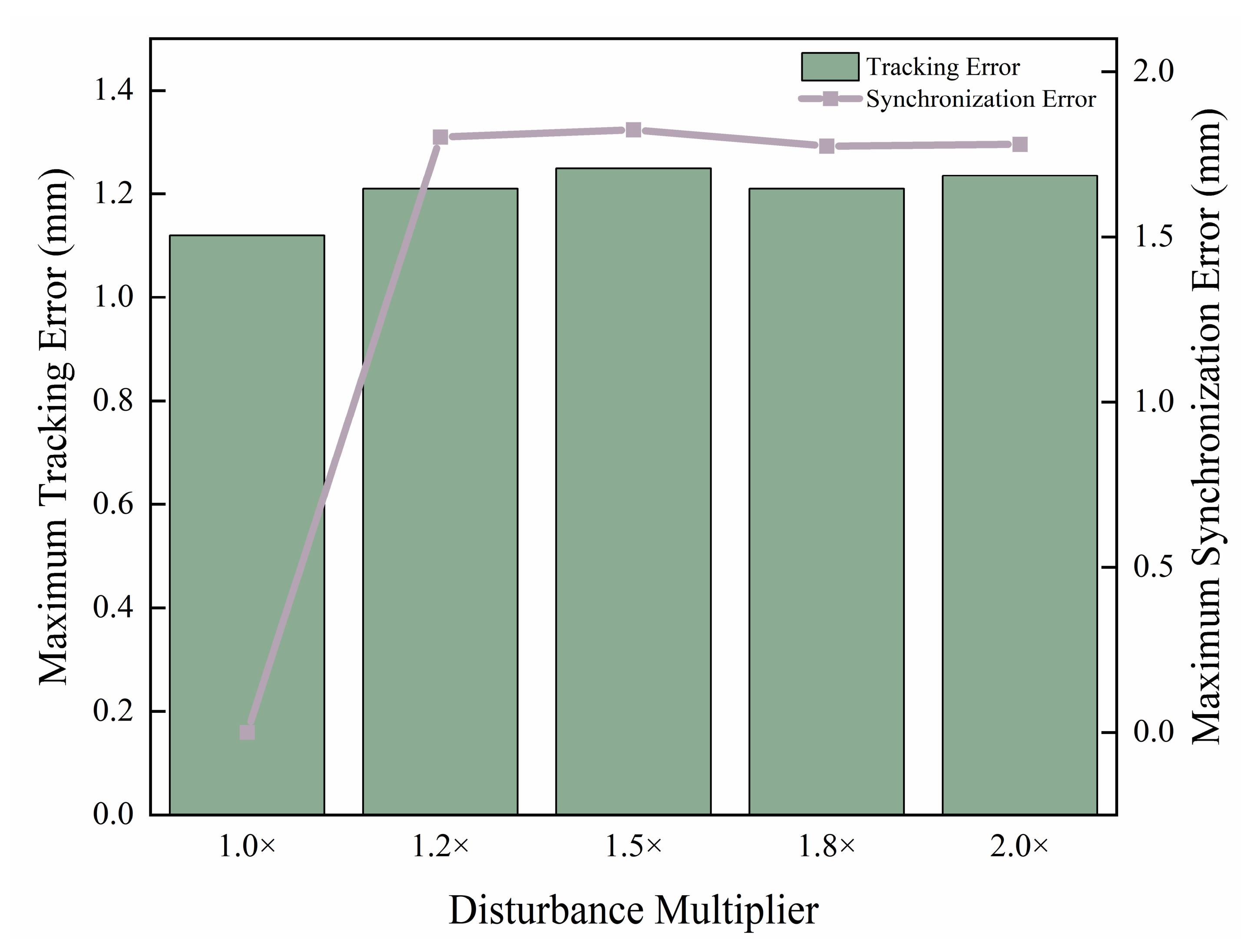
To further investigate the robustness boundary and the extreme limit of anti-eccentric loading of the proposed control strategy, gradient tests were conducted within the range of 1.0× to 2.0× asymmetric dynamic disturbance loads. The resulting maximum error envelope trends are illustrated in
Figure 11.
An analysis of
Figure 11 reveals that the system possesses formidable resilience against extreme asymmetric eccentric loads. On the one hand, the maximum tracking error, represented by the green bar chart, is maintained within a narrow frequency band of 1.12–1.25 mm across the entire load spectrum, highlighting the macroscopic disturbance-rejection stiffness of the adaptive control law. On the other hand, the maximum synchronization error trajectory, denoted by the purple line, indicates that after an initial logical physical transient jump induced by the onset of asymmetric eccentric loading (1.2×), the synchronization error does not exhibit linear or exponential divergence as the load continues to aggressively scale up to 2.0×. Instead, it is firmly bounded near a horizontal threshold of approximately 1.8 mm. This proves that the proposed cross-coupling mechanism can effectively suppress the divergent instability of multiple cylinders under limit working conditions, maintaining overall synergistic integrity.
3.3. Quantitative Comparative Analysis with Baseline Controllers
To quantitatively evaluate the performance of the proposed control strategy, a comparative analysis was conducted against two established baseline controllers: a decentralized Proportional-Integral-Derivative (PID) controller with feedforward (FF) compensation, and a classical full cross-coupling controller. The evaluation was performed under identical multi-cylinder plant dynamics and subjected to three distinct working conditions: nominal conditions, measurement noise injection, and a 1.2 times asymmetric dynamic eccentric load. The primary performance metrics—including maximum overshoot, settling time, tracking Root Mean Square (RMS) error, maximum synchronization error, synchronization RMS error, and qualitative convergence status—are summarized in
Table 3.
As summarized in
Table 3, the proposed method demonstrates quantitative improvements over the baseline controllers across all tested conditions. Under nominal conditions, the proposed method achieves a synchronization error of 5.88 × 10
−10 mm and a tracking RMS error of 0.33 mm, outperforming both the decentralized PID and classical cross-coupling controllers. Under measurement noise, the baseline controllers experience high-frequency chattering, whereas the proposed method maintains smooth convergence with a maximum synchronization error constrained to 0.82 mm. Under the 1.2 times eccentric load, the PID and full cross-coupling controllers exhibit severe synchronization degradation—reaching maximum errors of 37.65 mm and 13.28 mm, respectively—alongside actuator saturation. Conversely, the proposed adaptive strategy restricts the maximum synchronization error to 1.82 mm and the maximum overshoot to 3.25 mm, ensuring stable and smooth operation without saturation.
4. Conclusions
This paper addresses the anti-falling and synchronous control issues during the operation of hard-rock tunnel boring machines in large-inclination shafts. The Anti-Back-Slip support system of pumped-storage power stations is taken as the research object. Driven by its operational characteristics and engineering requirements, a multi-cylinder electro-hydraulic servo synchronous control system is designed. A nonlinear state-space mathematical model of the electro-hydraulic position servo system is constructed, and an adaptive backstepping controller is introduced into the adjacent cross-coupling strategy. Through the co-simulation analysis using the AMESim-Simulink platform, the main conclusions are drawn as follows:
The system exhibits steady-state synchronization under nominal conditions. When tracking sinusoidal and multi-frequency composite desired trajectories, the adjacent cross-coupling mechanism limits the inter-cylinder synchronization error. Sensitivity analyses across multiple solvers verify the asymptotic convergence of the nonlinear control law.
The control strategy demonstrates robust disturbance-rejection stiffness. Continuous broadband white noise was introduced to simulate sensor noise and external random perturbations. Under these conditions, the controller completes dynamic compensation within 1 s following internal system excitations. This enables the error to reconverge rapidly, maintaining stable system operation.
The system maintains synergistic capability against asymmetric eccentric loads. When subjected to suddenly applied asymmetric dynamic eccentric loads of 1.0 to 2.0 times, the multi-cylinder synchronization error avoids divergence, with the maximum error restricted to 1.82 mm, preventing multi-cylinder instability.
Comparative analyses indicate that the proposed strategy outperforms decentralized PID with feedforward compensation and classical full cross-coupling controllers. It reduces tracking and synchronization RMS errors and eliminates the actuator saturation observed in baseline controllers under severe eccentric loads.
In summary, the proposed control strategy addresses the limitations of traditional linear control algorithms in heavy-duty and eccentric load environments, achieving coordinated control among multiple actuators. The research findings satisfy the requirements for synchronous control of the anti-falling system in inclined shaft TBMs and provide a theoretical and engineering reference for the disturbance-rejection coordination of inclined shaft TBM support systems.
However, this study has certain limitations. The 10−12 m synchronization precision demonstrated in the simulations represents a theoretical mathematical bound within a double-precision environment. While the designed ABS system has been applied in a 5020 m excavation project, achieving actual macroscopic control precision at the millimeter level, practical performance is fundamentally bounded by physical hardware constraints. Furthermore, a dedicated independent physical test rig or Hardware-in-the-Loop (HiL) setup was not constructed in this study to isolate and evaluate the proposed algorithm. Therefore, future research will focus on establishing HiL testing environments and scaled physical test rigs to evaluate the engineering performance of the control law under actual hardware limitations. Additionally, subsequent studies will incorporate comparative analyses with other advanced nonlinear control strategies, such as Sliding-Mode Control and Robust Model Predictive Control, to systematically evaluate control energy consumption and stability margins.