Article

A Fast Response, High Flow Rate, Low Power Consumption Pneumatic Proportional Valve for Medical Ventilators Driven by a Piezoelectric Bimorph

1
School of Automation, Beijing Institute of Technology, Beijing 100081, China
2
Zhengzhou Research Institute, Beijing Institute of Technology, Zhengzhou 450000, China
3
Beijing Aerospace Propulsion Institute, Beijing 100006, China
*
Authors to whom correspondence should be addressed.
Actuators 2025, 14(9), 463; https://doi.org/10.3390/act14090463
Submission received: 20 July 2025 / Revised: 16 September 2025 / Accepted: 18 September 2025 / Published: 22 September 2025
(This article belongs to the Section Actuators for Medical Instruments)

Abstract

In recent years, pneumatic proportional valves have become increasingly prevalent in ventilators, particularly proportional solenoid valves. However, these traditional valves face challenges, including a slow response, being prone to overheating from long-term work, and high power consumption. This study presents the development of a fast response, high flow rate, and low power consumption pneumatic proportional valve specifically designed for medical ventilators. Utilizing a piezoelectric bimorph as the actuator, we innovatively eliminate movable components such as springs while ensuring effective sealing of the valve. A support structure was designed to enhance the mechanical performance of the piezoelectric bimorph. A testing platform was established to rigorously assess the valve’s performance. The results indicate that the valve can achieve a maximum output flow rate of approximately 130 L/min at an input pressure of 4 bar, with a hysteresis rate of 25.3%, a response time of under 10 ms, and a power consumption of just 0.07 W. Furthermore, a comparative analysis with existing commercial proportional solenoid valves demonstrated that it has superior performance in terms of response speed, flow rate, and power efficiency. The piezoelectric proportional valve developed in this study holds the potential to replace conventional proportional solenoid valves, significantly enhancing the response speed of ventilators, reducing their overall power consumption, and facilitating the development of portable ventilators.

1. Introduction

In modern clinical medicine, ventilators are vital devices that provide mechanical ventilation to patients unable to breathe independently or those with inadequate spontaneous ventilation [1]. They are commonly used to treat respiratory conditions, including acute respiratory distress syndrome and pneumonia. Recently, the incidence of respiratory diseases has been progressively increasing due to the growing challenges of population aging and environmental pollution. Consequently, ventilators have gained widespread application in clinical settings and are deemed essential medical equipment. A proportional valve is an electrically controlled valve with a continuously adjustable opening, which is typically used to precisely regulate the output flow rate of a ventilator [2,3]. A proportional solenoid valve is a specific type of proportional valve that adjusts the displacement of the valve core by varying the magnetic field strength through changes in the solenoid valve’s current [4,5]. Under the influence of a magnetic field force, the valve core overcomes resistance such as the spring force, moving upward or to one side, thus opening the valve channel and enabling gas to flow from the inlet to the outlet. Proportional solenoid valves facilitate the conversion of electrical and mechanical energy via electromagnetic fields, ensuring continuous and stable proportional output flow control. Presently, most ventilators available in the market employ proportional solenoid valves for airflow control. However, traditional proportional solenoid valves often have higher weights and larger volumes due to the properties of their core valve materials. Furthermore, they are characterized by a slow response, being prone to overheating from long-term work, and high power consumption due to their electromagnetic components’ physical attributes. Additionally, traditional solenoid valves may be vulnerable to oxidation and corrosion in environments with excessively high oxygen levels.
Piezoelectric ceramics are versatile materials that have been gradually discovered and refined with the development of piezoelectricity [6,7,8,9,10]. They can achieve mutual conversion between deformation and voltage, and the displacement of piezoelectric ceramics varies linearly with the driving voltage. These materials can be used as driving components for pneumatic servo valves. The principle of a piezoelectric proportional valve is based on the inverse piezoelectric effect [11]. When the direction of the electric field applied to the piezoelectric ceramic matches its polarization direction, the ceramic will undergo a stretching motion in line with the electric field [12,13,14]. Piezoelectric valves are extensively employed in research fields such as microelectromechanical systems [15], aerospace [16], drug delivery [17], and software robots [18,19] where high requirements for output flow rate, working pressure, responsiveness, flexibility, and reliability are essential. As pneumatic technology undergoes intelligent transformation, there is a growing need for innovative advancements in the structure and performance of pneumatic systems and components. Therefore, conducting in-depth research on piezoelectric valves is of great significance. Compared to proportional solenoid valves, piezoelectric proportional valves boast advantages such as a lightweight design, low power consumption, a rapid response, high control precision, and minimal noise. Consequently, designing and developing a dedicated piezoelectric proportional valve for ventilators are essential.
The primary piezoelectric actuators in pneumatic piezoelectric proportional valves consist of piezoelectric ceramic stacks and piezoelectric bimorphs. While offering substantial output force and minimal output displacement, stacked piezoelectric actuators possess larger dimensions and necessitate higher driving voltages [20]. Fazal et al. [21] developed a normally open piezoelectric stack-driven microvalve. Under a pressure difference of 4 bar, the flow rate was 250 mL/min. Continuous and controllable gas flow could be achieved at any stage of valve operation. Park et al. [22] designed, manufactured, and tested a piezoelectrically actuated microvalve with integrated sensors for flow modulation at low temperatures. The valve consists of a micromachined die fabricated from a silicon-on-insulator wafer, a glass wafer, and a commercially available piezoelectric stack actuator. Gas flow modulation from 200 to 0 mL/min was achieved at room temperature using 0 to 40 V actuation. Debin et al. [23] utilized piezoelectric actuators, which employ a flexible hinge displacement amplifier as the transmission mechanism and a piezoelectric stack actuator as the primary driver for the weft control valve. Operating under a voltage of 150 V, these actuators achieved a maximum output displacement of 42 μm and a peak thrust of 1200 N.
Compared to their length, the displacement generated by piezoelectric actuators is minimal. To achieve greater flow, it is necessary to amplify the stroke of the piezoelectric actuator through a flexible mechanism. According to Ref. [24], a piezoelectric actuator with dimensions of 10 mm × 10 mm × 36 mm can produce a displacement of 198 μm. Moreover, an even larger stroke was achieved with the displacement amplification of a flexible mechanism and an input voltage of 120 V. However, while stacked piezoelectric actuators can generate significant output force, their mechanical size and weight make them unsuitable for lightweight applications.
Piezoelectric bimorph structures have a relatively lower output force than other piezoelectric actuators. However, they boast the most significant output displacement in the millimeter range. Their compact design contributes to the miniaturization of valves, making them an ideal choice for driving piezoelectric valves. Groen et al. [25] created a micro-control valve with a top-mounted piezoelectric bimorph actuator, obtaining a high-bandwidth proportional control valve for gases in the range of several grams per hour. Yun et al. [26] proposed and studied a bimorph-type PZT actuator (25.2 mm × 7.2 mm × 0.5 mm) using a softener-type PZT with a constant of −220 × 10−12 CN−1, a carbon plate as a shim, and a controller circuit. The displacement of the actuator measured at the end was 63 μm, the force on the actuator was 0.052 N, and the maximum operating frequency was 15 Hz. Dong et al. [27] presented piezoelectric ring-morph actuators designed to produce a large flexural displacement for valve actuation application, with a maximum generated force of approximately 30 N.
Piezoelectric bimorphs are highly suitable for designing and driving small pneumatic piezoelectric proportional valves due to their low cost, compact size, high resolution, and rapid frequency response. Nevertheless, their low output force significantly restricts their application scenarios, limiting their use primarily to low-flow fields such as microvalves and precision mechanical drives. Improving the output force of the piezoelectric bimorph structure and balancing it with the turbulent aerodynamic force for application in high-flow pneumatic proportional valves remain unresolved issues. Furthermore, analysis must be performed for various scenarios in experiments, considering the hysteresis, creep, and output characteristics of piezoelectric ceramics.
To further expand the application of piezoelectric technology in pneumatic systems, this study designed a fast response, high flow rate, low power consumption pneumatic proportional valve for medical ventilators using piezoelectric bimorph technology and conducted relevant experimental verification. Firstly, we conducted a force analysis on the piezoelectric bimorph and summarized the working principle and characteristics of the nozzle baffle piezoelectric proportional valve. Secondly, based on the gas flow calculation method, we selected piezoelectric bimorphs that meet the performance indicators and simulated and verified their displacement and output. Finally, we conducted validation experiments on the designed and manufactured pneumatic proportional valve. We compared it with existing commercialized solenoid valves and demonstrated the superiority of our developed valve. We provide in-depth discussions and evaluations of the experimental results. Our design philosophy advocates for the use of piezoelectric valves rather than solenoid valves in ventilators while seeking to maximize the applications of our designed valves. Our innovation lies in solving the problem of low flow rates in traditional proportional valves based on piezoelectric bimorphs. The problem with traditional structures is that the output force of piezoelectric bimorphs is too low, making it difficult to overcome aerodynamic forces at high flow rates. Our core idea is to increase the output force of piezoelectric bimorphs to a sufficiently high level while ensuring that their end displacement is large enough.

2. Materials and Methods

Proportional valves designed for ventilators require a maximum operating pressure of 4 bar and an output flow rate exceeding 120 L/min. Due to the limited output force of a cantilever beam piezoelectric bimorph, traditional nozzle-flapper piezoelectric proportional valves are generally used in low-pressure and low-flow situations. To meet the specific application requirements of ventilators, it is essential to first determine the critical parameters of the valve structure and valve body and the performance specifications of the piezoelectric bimorph.

2.1. Working Principle and Structural Design

The principle of bending in piezoelectric bimorphs is governed by the inverse piezoelectric effect. When an electric field aligns with the polarization of the piezoelectric layer, it causes longitudinal elongation and transverse contraction. If the upper layer’s polarization matches the electric field’s direction while the lower layer has the opposite polarization, the upper layer contracts laterally, and the lower layer expands, resulting in upward warping of the piezoelectric bimorph. In addition, creep and hysteresis during deformation are intrinsic properties of piezoelectric materials. These factors can affect the flow output characteristic curve of the piezoelectric valve, leading to issues such as hysteresis and dead zones.
Figure 1a illustrates the working principle of the improved pneumatic piezoelectric proportional valve presented in this study. r1 is the radius of the air outlet, r2 is the radius of the air inlet, and h is the displacement of the free end of the piezoelectric bimorph. When the power is off, the output force of the piezoelectric bimorph is zero, and the cantilever beam structure provides only basic mechanical support. As a result, the end seal of the piezoelectric bimorph cannot adhere tightly to the air outlet, leading to a small air gap and causing leakage in the proportional valve.
This study designed an independent and detachable nozzle structure, as depicted in Figure 1b,c. The outer wall of the nozzle is threaded, allowing for adjustable height within the valve chamber. This adjustment facilitates close contact between the nozzle and the piezoelectric bimorph. The piezoelectric bimorph, configured with a cantilever beam installation, exhibits a lower output force (F1). The air outlet’s positioning below the piezoelectric bimorph results in a significantly higher airflow velocity beneath it compared to above. This velocity difference induces a pressure differential at the bimorph’s end. At this point, the aerodynamic force (F2) becomes relevant. When F2 approaches F1, the displacement motion of the piezoelectric bimorph is hindered. Consequently, narrowing the gap can significantly reduce the gas flow rate. Should F2 exceed F1, the piezoelectric bimorph will be unable to deflect, leading to malfunction of the proportional valve.
In this study, triangular prism support structures were designed at the base of the valve chamber. These pivot structures provide a support point for the bending deformation of the piezoelectric bimorph’s end, generating a supporting force (F3). This force partially counteracts the effects of the aerodynamic force (F2), ensuring that the piezoelectric bimorph maintains its deformation effect even under greater pressure differentials. Improvements were made to the valve chamber structure by eliminating the traditional spring preloading mechanism and introducing deformation support points for the piezoelectric bimorph. This design enhancement leads to better displacement output performance from the bimorph. We conducted experimental verification on the necessity and location of supporting structures in the next section. In general, it is vital to limit both the maximum working pressure and the maximum diameter of the outlet in a piezoelectric proportional valve.
The piezoelectric valve (78 mm × 41 mm × 13 mm), along with nozzles of varying diameters (2.2, 2.6, 3.0, and 3.4 mm), is depicted in Figure 1d. This valve was manufactured using 3D printing technology and SLA ultraviolet light curing and consists of a piezoelectric bimorph fixed to a base and a transparent valve cover made from photosensitive resin. Compared to traditional solenoid valves, this design offers several advantages, including reduced manufacturing costs, simplified production steps, and a lighter mechanical weight. The transparent valve cover allows for real-time monitoring of the piezoelectric bimorph’s displacement during operation, providing valuable visual feedback. Additionally, due to the capacitive nature of piezoelectric components, they only produce current during deformation, resulting in an almost-zero stable current. This feature significantly lowers the power consumption and heat generation of the valve, making it more efficient.

2.2. Determination of Key Parameters

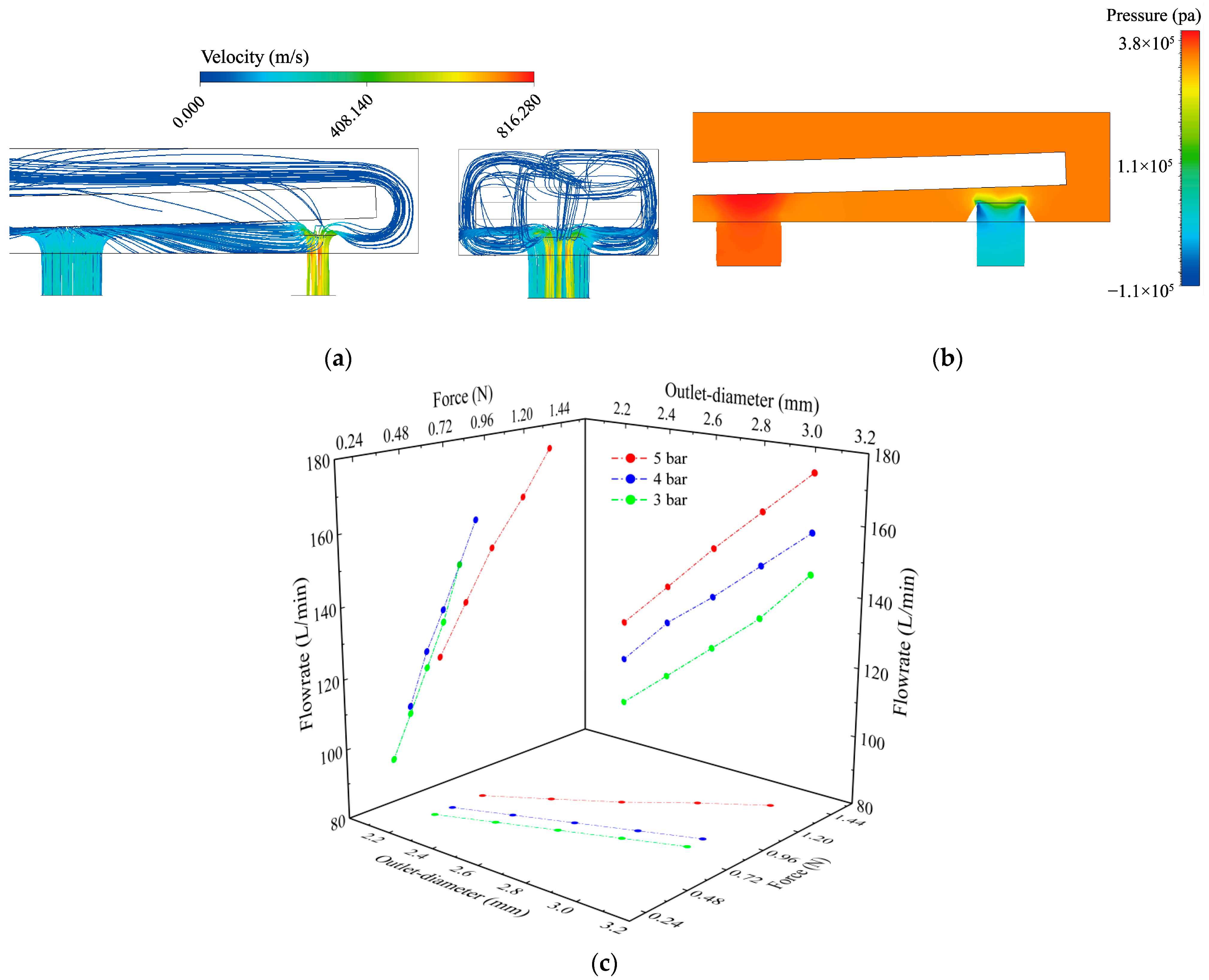
The diameter of the outlet and the pressure in the valve chamber will affect the piezoelectric proportional valve’s output flow rate. The aerodynamic force acting on the free end of the piezoelectric bimorph will affect its displacement, thereby affecting the valve opening. When using FIUENT for simulation in this study, we made the following assumptions: the gas inside the valve is an ideal compressible gas; the piezoelectric valve has no leakage; and the influence of wall friction and temperature on gas flow was ignored. We established the boundary conditions as a pressure inlet (4 bar, gauge pressure) and a pressure outlet (0 bar, gauge pressure) while employing the k-ε turbulence model in steady-state mode. The model was divided into 5110 cells. The time step was set to automatic, with the time scaling factor set to 1. The empirical parameters of the turbulence model in numerical simulation were set to the default values. Figure 2a shows the internal flow line diagram of the valve at a pressure of 4 bar with an outlet diameter of 2.4 mm. Figure 2b shows the stress cloud map at the center section of the valve. Figure 2c illustrates the relationship between outlet diameter and the aerodynamic force (F2) and output flow rate of the piezoelectric bimorph under varying pressures. From the YZ projection plane, it is evident that, with a constant air outlet diameter, an increased displacement at the end of the piezoelectric bimorph results in a higher output flow rate, alongside a greater aerodynamic force acting on the end. The XY projection indicates that, when the displacement at the end of the piezoelectric bimorph is constant, a larger air outlet experiences a greater aerodynamic force. The XZ projection shows that, with a constant displacement at the end of the piezoelectric bimorph, a larger air outlet correlates with a higher output flow rate. To mitigate the aerodynamic force that may hinder valve opening, it is essential to maintain this force at a lower level.
The rapid flow can be regarded as a one-dimensional isentropic process without considering other small eddies in the flow field because of the limited contact surface between the air passing through the small hole and the pipe wall.
Using the Bernoulli equation, the mass flow rate through the small hole can be determined [28]:
G = S e p 1 K G / θ 1 ,   p 2 / p 1 0.5 2 S e p 1 K G p 2 ( 1 p 2 / p 1 ) / p 1 / θ 1 , p 2 / p 1 > 0.5
In the equation, KG is the gas constant. When the gas flow reaches the speed of sound, the value of KG is 0.0403. θ1 signifies the absolute temperature of the upstream air, while p1 represents the gas pressure before flowing through the small hole, corresponding to the working pressure of the piezoelectric valve. p2 denotes the gas pressure after passing through the small hole, which reflects the pressure on the lower surface of the piezoelectric bimorph. Se represents the cross-sectional area of the airflow contraction, defined as the effective cross-sectional area of the small hole. It is smaller than the actual cross-sectional area S of the small hole, and the relationship between the two is as follows:
α = S e S S = π r 1 2 = 2 π r 1 h
α is the contraction coefficient, which varies based on the shape and size of the small hole inlet. Additionally, if we consider the valve opening to be cylindrical, we can determine the flow area S and the displacement h of the free end of the piezoelectric bimorph by measuring the outlet radius r1. Gas flows from the surrounding walls of the cylindrical region and exits through the bottom. When the lifting height of the piezoelectric bimorph is below 0.5r1, the reduced wall area around the cylindrical region creates a throttling effect. Conversely, when the lifting height exceeds 0.5r1, the smaller bottom area of the cylindrical region also induces a throttling effect. For ease of subsequent calculations using Formula (2), we temporarily assume that these two areas are equal and exert the same throttling effect.
When the valve is closed, the pressure differential Δp at the unconstrained end of the piezoelectric bimorph reaches its peak value. At this point, the aerodynamic force that opposes the bending motion of the piezoelectric bimorph achieves its maximum magnitude. Consequently, the maximum output force of the selected piezoelectric bimorph can be determined using the following formula:
F max = Δ p π r 1 2 = p 2 p 1 π r 1 2
We substitute the proportional valve pressure and flow rate required for the ventilator (pmax = 4 bar, Qmax = 120 L/min) into the above formula to obtain the following values:
S e = 3.4212   m m 2 F max = 1.521   N h = 0.55   m m

3. Experimental Results and Discussion

3.1. Preparation Experiment and Experimental Platform Construction

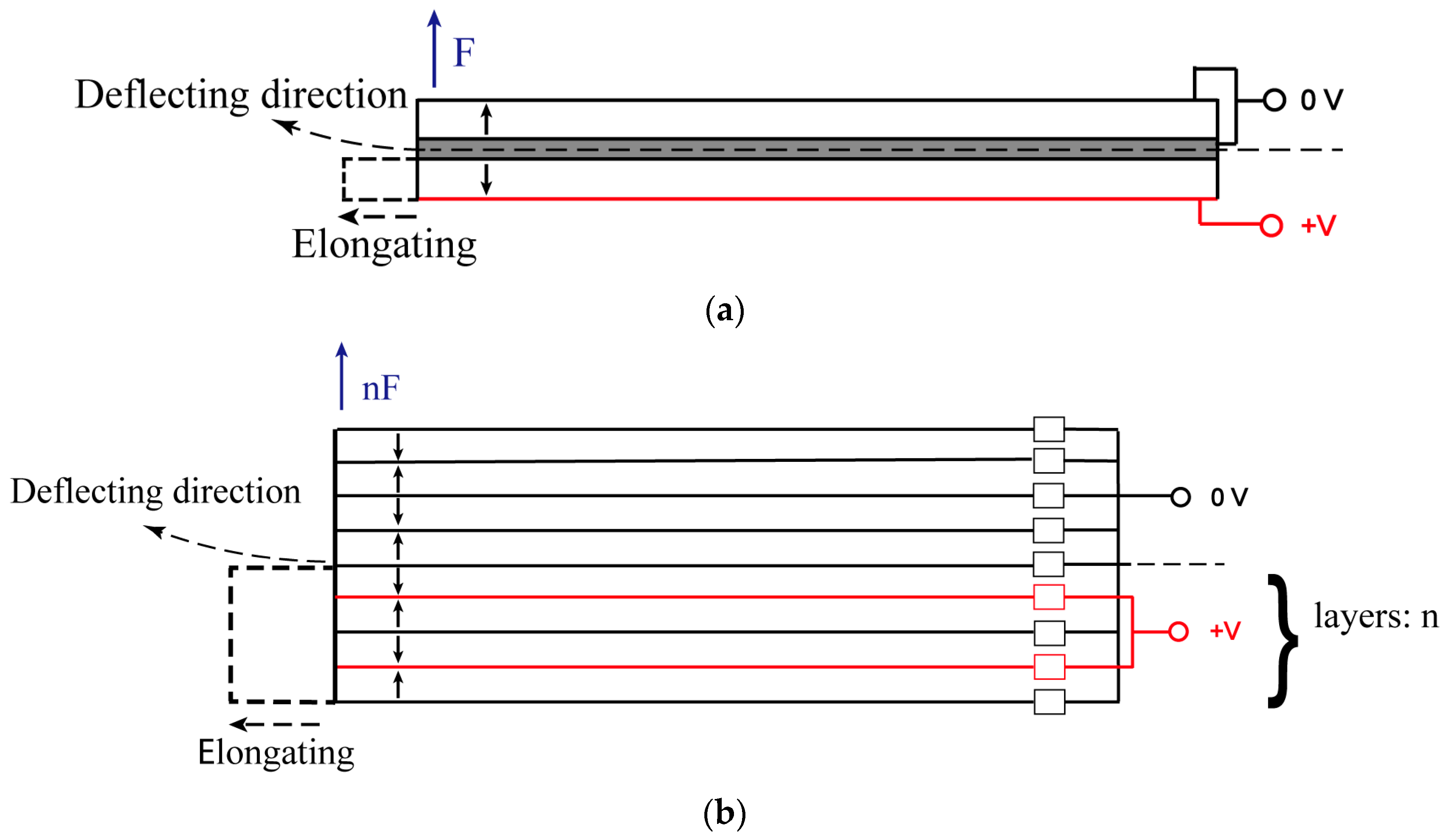
For the experiment where all the key parameters satisfy Equation (4), the piezoelectric bimorph from Core Tomorrow Science & Technology Co., Ltd, Harbin, China was chosen. The model and parameters are listed in Table 1. The piezoelectric bimorph consists of multiple layers of piezoelectric ceramics arranged in a specific polarization direction and stacked together. By connecting the end electrode to a piezoelectric driving power source, an electric field can be applied perpendicular to the surface of the piezoelectric bimorph, causing it to deflect to one side. Figure 3a illustrates the operational mechanism of a piezoelectric bimorph fabricated from ceramic stacks with alternating polarization orientations, wherein the arrows denote the polarization direction of individual piezoelectric layers. The gray part in the figure represents the middle metal layer, and the blue arrow represents its end output force. When subjected to an electric field opposing its polarization vector, the lower segment of the bicrystal undergoes axial elongation. In contrast, the upper segment remains electrically unstimulated, thereby exhibiting negligible deformation. Figure 3b shows the mechanism diagram of a piezoelectric bimorph composed of multiple layers stacked together. The characteristics of multi-layer stacking make its output force several times that of the former.
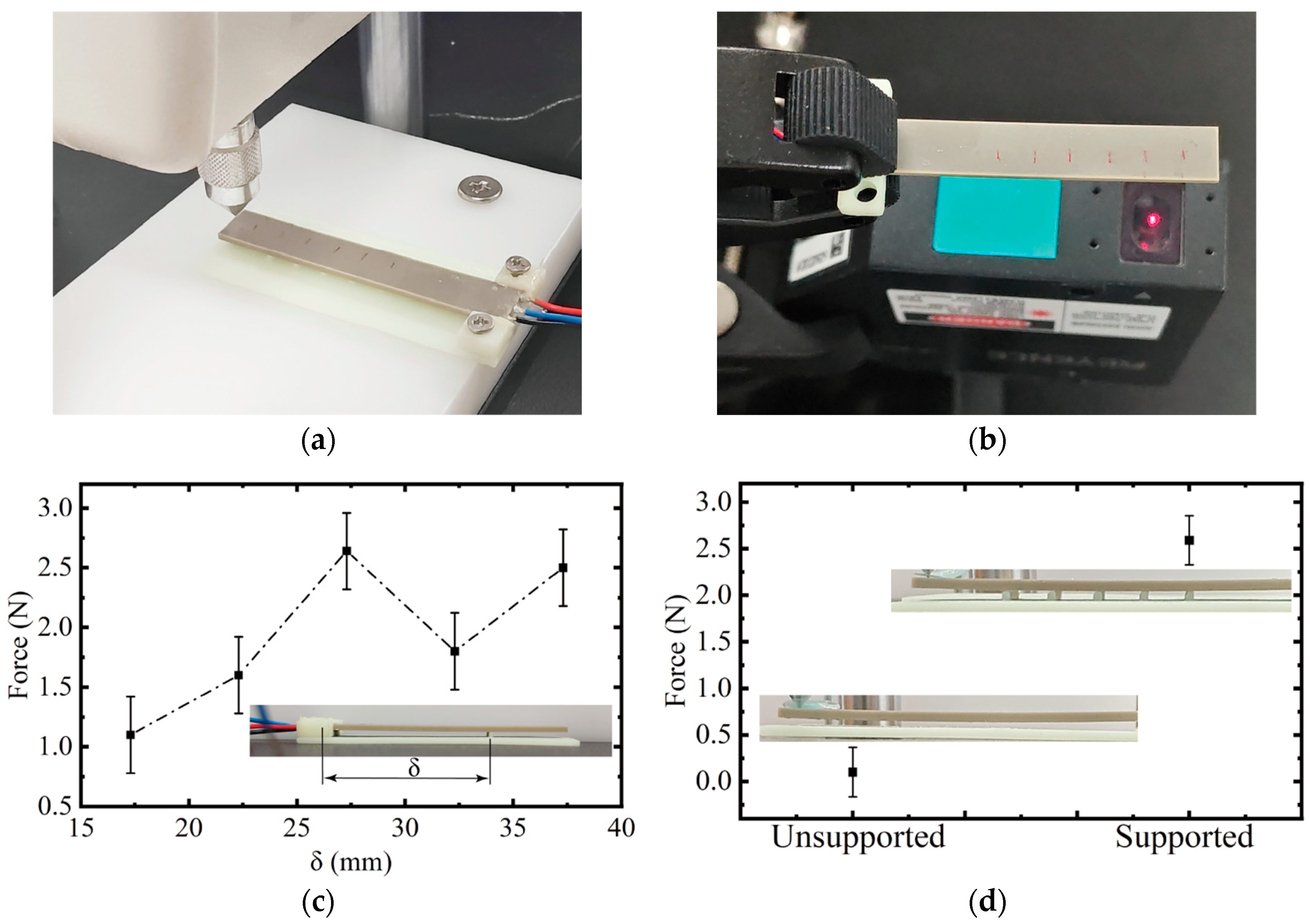
We fix the piezoelectric bimorph according to the cantilever beam installation method and place the probe of the force sensor horizontally at its free end, which was used to read the output data in real time. The force transducer (HF, Nohawk, Yantai, China) and displacement sensor (LK-G30, Keyence, Osaka, Japan) used in this experiment are shown in Figure 4a and b, respectively. We measured the output force of the piezoelectric bimorph at various positions of the triangular support prism structures, with the results illustrated in Figure 4c. The experimental results show that, when the fulcrum was farthest from the free end, the output force was only about 1 N. When the fulcrum was at the center position or close to the free end, the output force exceeded 2 N. Additionally, the experimental findings demonstrate that the support structure significantly enhanced the output force of the piezoelectric bimorph, leading to varying bending deformations depending on the fulcrum’s position. When the fulcrum was situated in the middle of the piezoelectric bimorph (δ = 27.3 mm), the concave deformation was minimized, resulting in maximum output force. The optimal position for installing the support structures changed depending on different working pressures. Figure 4d illustrates the output at the free end of the piezoelectric bimorph, with and without support, further underscoring the necessity of support structures. To accommodate various pressure changes, we chose five equidistant points as supports.
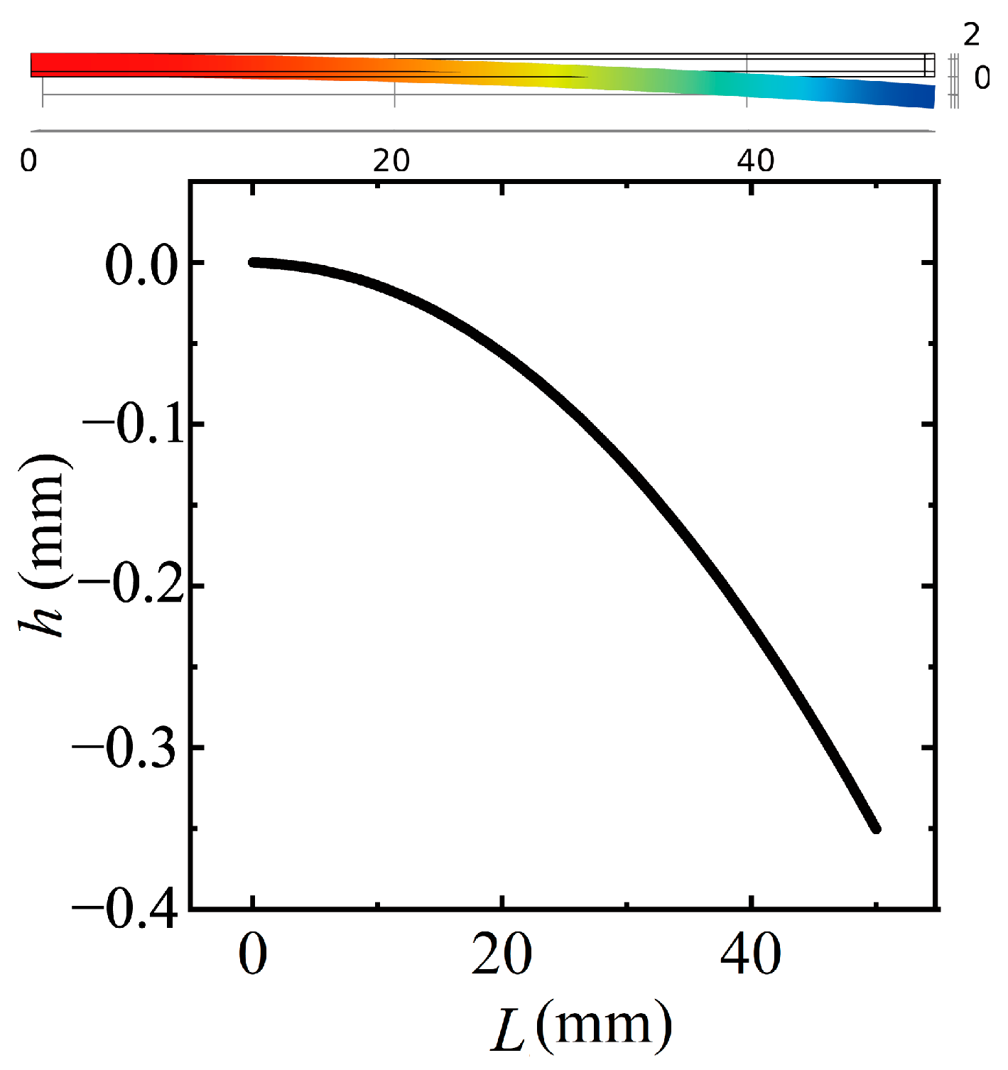
To further understand the behavior of the piezoelectric bimorph, we performed simulations of its deformation using COMSOL Multiphysics 6.2 as depicted in Figure 5. The sampling point spacing of this curve was 0.55 mm. The simulation utilized solid mechanics while integrating piezoelectric materials and electrostatics. The bimorph was configured as a cantilever beam, and the material selected for this model was lead zirconate titanate (PZT-5H). The constitutive relationship for the material was set to the strain-charge type. A grid count of 300 was established for the model mesh. The specified material parameters were d31 = −2.74 × 10⁻¹² m/V, Y11 = sE11 = 1.65 × 10⁻¹¹ Pa, and E = 200 V. In the COMSOL simulation, we applied a gradually increasing opposing restraining force at the end of the piezoelectric bimorph. As this force increased, the end displacement of the bimorph decreased.
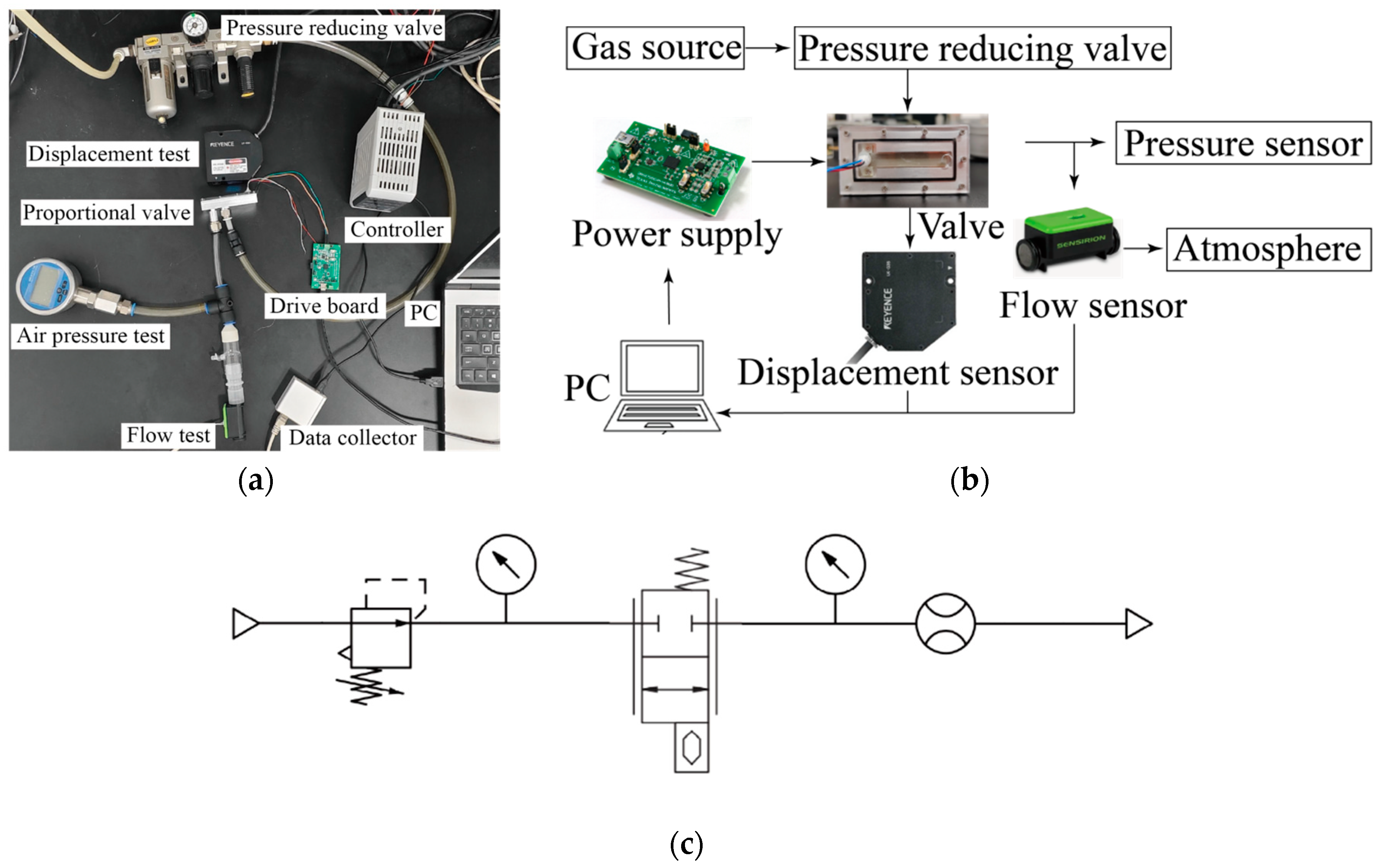
Figure 6a,b illustrate the connection method for the experimental hardware components, and the pneumatic diagram of the experimental system is shown in Figure 6c. The system includes a pressure relief valve that maintains the air source pressure at a predetermined value. The piezoelectric driving circuit board (DRV2700EVM-HV500, Texas Instruments, Dallas, TX, USA) boosts the input voltage (from 3.2 V to 0 V) in a reverse linear manner to achieve an output of 0–200 V through a flyback configuration, effectively driving the piezoelectric bimorph. The output port of the piezoelectric proportional valve connects to a flow sensor (SFM3119, Sensirion, Zurich, Switzerland), while the pressure sensor (SIN-Y190, Sinomeasure, Hangzhou, China) is positioned between the proportional valve and the flow sensor. We supply power to the piezoelectric valve via a piezoelectric drive circuit board while recording the output flow rate in real time using a flow sensor. Additionally, we employed displacement sensors to monitor the displacement of the end of the piezoelectric bimorph in real time, allowing us to determine the size of the valve opening. All sensor data was recorded on the PC. During experimentation, we ensured that the gauge pressure difference between the pressure relief valve and the pressure sensor was maintained at 4 bar, allowing for controlled testing of the valve’s performance under consistent pressure conditions.

3.2. Experimental Verification and Result Analysis

Figure 7a illustrates the relationship curve between the maximum output flow rate of the proportional valve and the working pressure for various outlet diameters. In the experiment, the voltage change rate was set at 7 V/s. We increased the voltage from the dead zone voltage to 212 V and then decreased it back to the dead zone voltage while measuring the flow characteristic curves during both processes. The results show that the output flow rate of the proportional valve initially increased with working pressure but subsequently decreased, indicating a nonlinear relationship. Each nozzle diameter had a corresponding maximum working pressure, denoted as pmax, which determines its maximum output flow rate. For instance, a nozzle with a diameter of 2.2 mm achieved a maximum output flow rate of approximately 130 L/min when subjected to a pressure of 4 bar. As the working pressure increased, the limitations on the deformation of the piezoelectric bimorph became more pronounced. When the air pressure exceeded the pmax for each nozzle diameter, it became increasingly difficult for the piezoelectric bimorph to deform effectively. Figure 7b illustrates the displacement–pressure relationship curve for the free end of the piezoelectric bimorph under various outlet diameters. As shown in the figure, higher working pressures resulted in more pronounced deformation limitations of the piezoelectric bimorph. When the air pressure exceeded the maximum working pressure (pmax) corresponding to each of the four nozzles, the piezoelectric bimorph exhibited a significantly reduced deformation capability.
The flow curves of the proportional valve under four nozzle diameters at five pressures (1, 2, 3, 4, and 5 bar) are presented in the Supplementary Materials. These results reveal that the pressure rise flow curve and pressure drop flow curve of the piezoelectric valve do not align, demonstrating a significant hysteresis characteristic. Specifically, the hysteresis rate and dead zone voltage of the flow curve at a pressure of 4 bar are highlighted in Figure 7c. As FESTO’s VPWS is a proportional solenoid valve that is currently used in ventilators, we compared its flow characteristic curve with that of our developed value to verify its effectiveness. We evaluated the operating characteristic curve of the VPWS at a pressure of 4 bar, as illustrated in Figure 7d. In the experiment, the current change rate was set at 150 mA/s. We increased the current from the dead zone level to 0.24 A and then decreased it back to the dead zone level while measuring the flow characteristic curves during both processes. Notably, our valve showed performance characteristics comparable to those of the VPWS, underscoring the importance and relevance of our advancements in the development of piezoelectric valves for applications such as ventilators. This similarity in performance demonstrates the potential of our design to effectively meet the needs of modern ventilatory support devices.
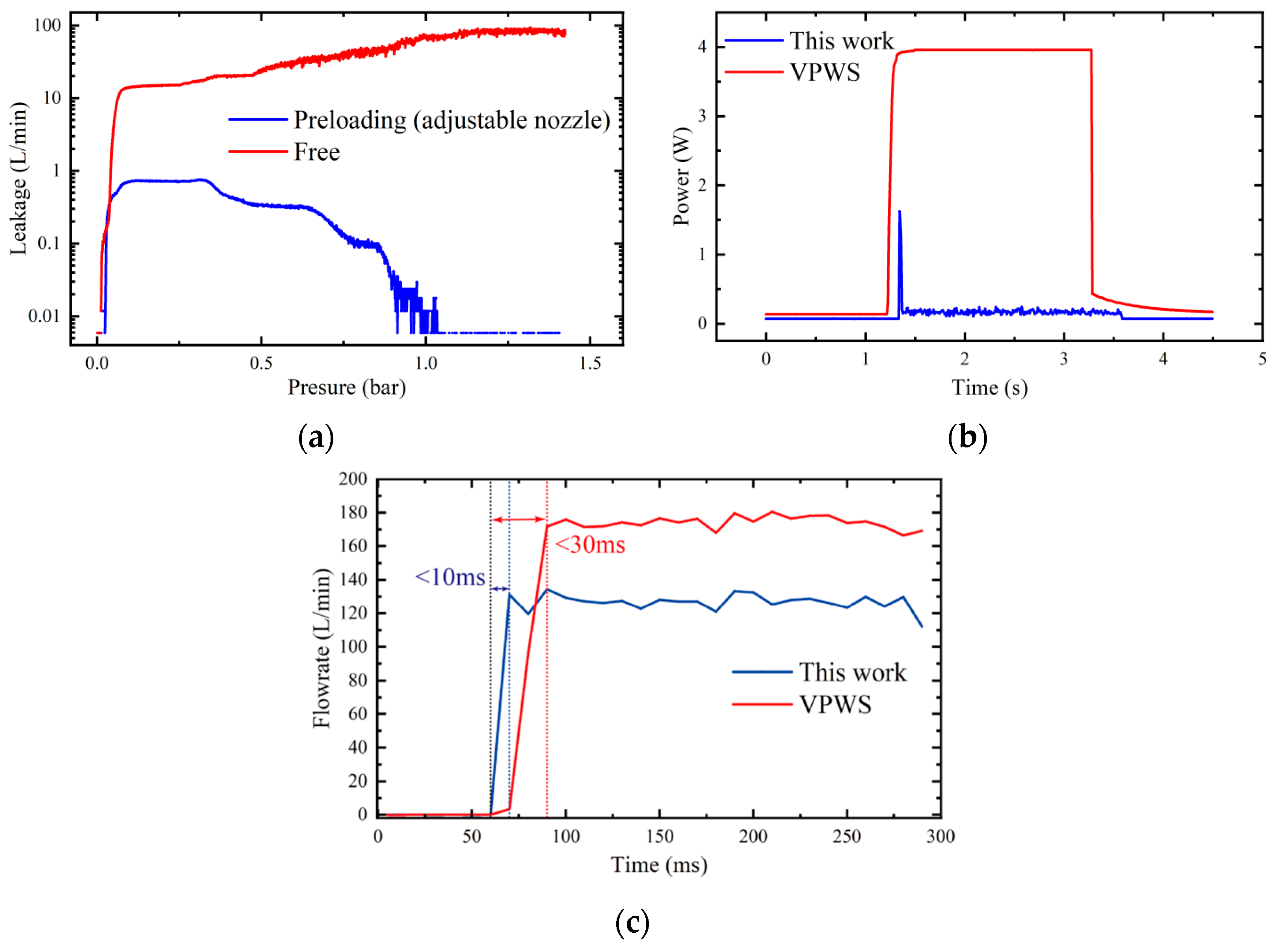
We conducted separate tests to evaluate the leakage of valves with and without adjustable nozzles. As illustrated in Figure 8a, the valve we designed eliminates the need for spring constraints; consequently, using a valve without an adjustable nozzle resulted in significant leakage. Upon installation of the adjustable nozzle, the leakage rate of the valve was less than 0.7 L/min at low pressures (below 0.5 bar). However, at pressures exceeding 1 bar, the leakage of the valve was almost negligible. These experimental results underscore the importance of adjustable nozzles, as such leakage can be considered acceptable given that ventilators typically operate in high-pressure environments.
Figure 8b compares the electrical power consumption of our piezoelectric valve with that of the VPWS. The sampling frequency for power consumption measurement in the experiment was 100 Hz. Due to the capacitive nature of the piezoelectric bimorph, current was generated almost exclusively at the moment of bending when electricity was applied. Consequently, its peak power consumption was several times higher than average. Once the piezoelectric bimorph was fully charged, the power consumption of the VPWS valve remained significantly higher than that of our design. Figure 8c presents the step response curves for both valves, highlighting the superior response speed of the piezoelectric proportional valve. The sampling frequency of the flow sensor in the experiment was 100 Hz. Table 2 provides a comparison of the various parameters of our valve and the VPWS and VEAE (the pneumatic piezoelectric proportional valve from FESTO): the flow rate, hysteresis, power consumption, frequency response, response time, weight, and volume parameters. The results indicate that the piezoelectric valve we developed exhibits a high hysteresis rate, which was attributed to the inherent characteristics of piezoelectric materials. As shown in Figure 7c, the flow characteristic curves of the valve do not overlap when the driving voltage was increased and decreased, with a maximum hysteresis rate of 25.3%. Therefore, we plan to address this issue through the development of improved piezoelectric control algorithms in future work. Additionally, although our piezoelectric actuator has a low mass, the valve body housing we are currently designing is relatively bulky; thus, future efforts will focus on optimizing the volume of the valve. Furthermore, while the VEAE has achieved a very light weight, our valve offers a larger output flow rate.
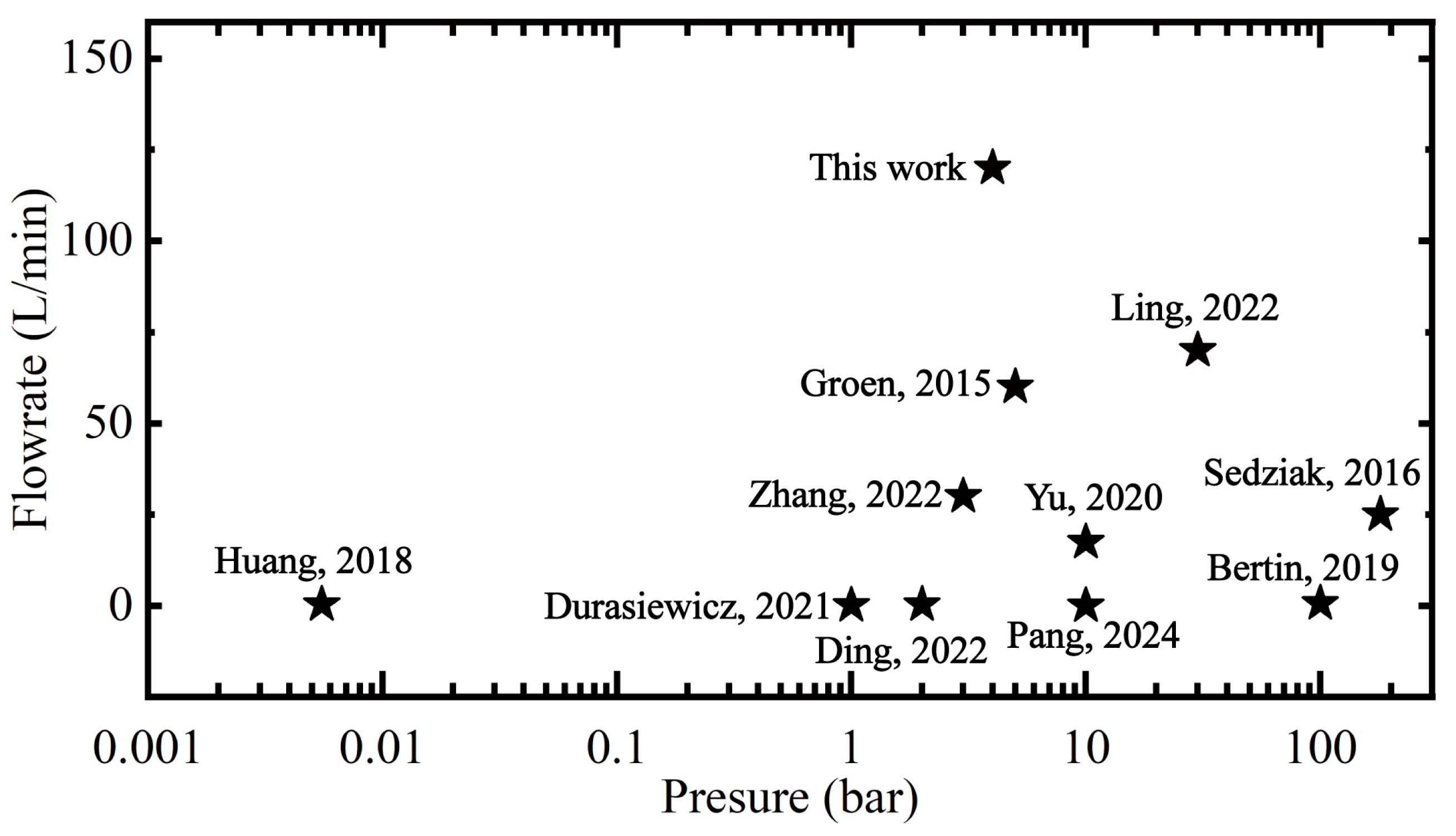
Figure 9 compares the flow rate and working pressure of our valve and other piezoelectric valves fabricated with piezoelectric bimorphs [16,29,30,31], highlighting the superiority of this approach. The figure shows the maximum flow and working pressure points. At present, the only known piezoelectric valve that can be applied to ventilators is FESTO’s commercial product VEAE, which we tested in our previous study [29] and found that our developed valve has a larger output flow rate. In addition, we compared several other valves based on piezoelectric bimorphs or piezoelectric stacks. Huang et al. [30] developed a microvalve using an actuator composed of two piezoelectric bimorphs (50 mm × 5 mm × 0.4 mm). Still, the lower displacement of the piezoelectric bimorphs (0.103 mm) resulted in a lower working pressure and flow rate for the valve. In addition, some researchers used piezoelectric bimorphs as pilot valves to generate pressure differences through the deflection of the piezoelectric bimorphs, thereby causing displacement of the central valve core. This method allows the main valve to operate in high-pressure situations. Sedziak et al. [31] used piezoelectric bimorphs instead of traditional electromagnetic/torque motors to develop nozzle baffles and jet deflectors for flow valves. Their results from model simulations (120 bar) and servo valve experiments (180 bar) focused on applications in the aerospace field. Bertin et al. [16] designed, constructed, and tested a pilot-stage piezoelectric aviation engine fuel valve driven by a piezoelectric ring bending machine. Ling et al. [11] developed a novel two-stage flow control valve driven by an amplifying piezoelectric actuator, with a step response time of 5 ms and a flow rate of 70 L/min at a supply pressure of 30 bar. Pang et al. [32] designed a piezoelectric valve that can operate in three driving frequency modes, with corresponding maximum flow rates of 3.3, 1.15, and 0.445 mL/min. Durasiewicz et al. [33] proposed a normally open microvalve that utilizes an energy-saving piezoelectric drive, wherein an additional coating on the valve seat enhances sealing performance. Zhang et al. [34] developed a pneumatic high-speed on–off valve with a maximum flow rate of 30.7 L/min under a pressure difference of 3 bar. Ding et al. [35] proposed a MEMS-based microvalve with piezoelectric actuators to achieve continuously adjustable flow control. Yu et al. [36] developed a high-speed switch control valve driven by a piezoelectric actuator and proposed a structure for a bridge displacement amplifier. Compared to similarly driven valves utilizing piezoelectric bimorphs, our work demonstrates superior flow rate performance.

4. Conclusions

This study proposes a design scheme for a high-flow pneumatic proportional valve utilizing a piezoelectric bimorph specifically for ventilators and presents experimental verification of the design. The piezoelectric bimorph, which is affixed to a cantilever beam, is capable of regulating the valve’s output flow rate. The characteristics and operational principles of the valve are described, and numerical and simulation techniques were employed for a comprehensive analysis. The critical structural parameters of the valve were identified and optimized using fluid simulation software. Furthermore, the impact of the pressure differential on the displacement of the free end of the piezoelectric bimorph was elucidated. The challenge of a low output force from piezoelectric bimorphs is addressed by enhancing the valve chamber structure. Compared to recent research, the proposed valve achieves a greater flow rate while maintaining a lighter mechanical weight. When the nozzle diameter is 2.2 mm, the output flow rate of the piezoelectric valve at 4 bar exceeds 130 L/min. In addition, this work guides researchers in selecting a piezoelectric bimorph and designing key valve parameters for nozzle baffle pneumatic piezoelectric proportional valves. Finally, by comparing our developed valve’s performance parameters with those of similar products on the market, we demonstrated its superiority in terms of flow output, power consumption, and response speed. This capability could allow us to replace solenoid valves in ventilator applications and other scenarios. In the future, we will focus on optimizing the piezoelectric drive circuit and slightly increasing the conduction current of the piezoelectric bimorph to achieve higher operating frequencies. Subsequently, we will further reduce the volume of the existing proportional valve and develop optimized control algorithms to enhance control performance.

Supplementary Materials

The following supporting information can be downloaded at: https://www.mdpi.com/article/10.3390/act14090463/s1, Figure S1: Flow characteristic curve (nozzle diameter of 2.2 mm); Figure S2: Flow characteristic curve (nozzle diameter of 2.6 mm); Figure S3: Flow characteristic curve (nozzle diameter of 3.0 mm); Figure S4: Flow characteristic curve (nozzle diameter of 3.4 mm).

Author Contributions

Conceptualization, S.R. and J.C.; methodology, S.R. and J.C.; software, S.R. and J.C.; writing—original draft preparation, S.R. and J.C.; writing—review and editing, S.R. and J.C.; project administration, S.R., T.W. and B.M.; funding acquisition, S.R., T.W. and B.M. All authors have read and agreed to the published version of the manuscript.

Funding

This research was supported by the Beijing Natural Science Foundation (3232014) and the National Natural Science Foundation of China Foundation (52005015).

Data Availability Statement

The original contributions presented in this study are included in the article/Supplementary Material. Further inquiries can be directed to the corresponding authors.

Conflicts of Interest

The authors declare that they have no known competing financial interests or personal relationships that could have appeared to influence the work reported in this paper.

References

  1. Kacmarek, R.M. The mechanical ventilator: Past, present, and future. Respir. Care 2011, 56, 1170–1180. [Google Scholar] [CrossRef]
  2. Wallace, C.L.; Sanborn, W.G.; Arnett, D.; Butterbrodt, J.; Ferguson, H.L. Ventilator Breath Display and Graphic User Interface. U.S. Patent US5881723A, 16 March 1999. [Google Scholar]
  3. Zhang, Y.; Li, K.; Cai, M.; Wei, F.; Gong, S.; Li, S.; Lv, B. Establishment and experimental verification of a nonlinear position servo system model for a magnetically coupled rodless cylinder. Actuators 2022, 11, 50. [Google Scholar] [CrossRef]
  4. Zhu, J.; Han, P.; Qi, C.; Gong, G.; Yang, H.; Shinshi, T.; Han, D. A single-coil-driven tristable electromagnetic mini valve with multiple working states. Sens. Actuators A Phys. 2024, 377, 115699. [Google Scholar] [CrossRef]
  5. Pradeep, A.; Raj S., V.; Stanley, J.; Nair, B.G.; Babu, T.S. Automated and programmable electromagnetically actuated valves for microfluidic applications. Sens. Actuators A Phys. 2018, 283, 79–86. [Google Scholar] [CrossRef]
  6. Zak, A.K.; Yazdi, S.T.; Abrishami, M.E.; Hashim, A.M. A review on piezoelectric ceramics and nanostructures: Fundamentals and fabrications. J. Aust. Ceram. Soc. 2024, 60, 723–753. [Google Scholar] [CrossRef]
  7. Pang, Y.-J.; Wang, L.; Jin, J.-M. Design and Experimental Research of a High-Precision Piezoelectric Control Valve. In Proceedings of the 2022 16th Symposium on Piezoelectricity, Acoustic Waves, and Device Applications (SPAWDA), Nanjing, China, 10–14 October 2022. [Google Scholar]
  8. Brusa, E.; Carrera, A.; Delprete, C. A review of piezoelectric energy harvesting: Materials, design, and readout circuits. Actuators 2023, 12, 457. [Google Scholar] [CrossRef]
  9. Jones, N.A.; Clark, J. Analytical Modeling and Simulation of S-Drive Piezoelectric Actuators. Actuators 2021, 10, 87. [Google Scholar] [CrossRef]
  10. Morita, K.; Fujii, F.; Hosoda, K. Modeling and Compensation of a Bimorph Type Piezoelectric Actuator Exhibiting Odd-Harmonic Oscillation and Frequency-Dependent, Interleaved Hysteresis. Actuators 2020, 9, 36. [Google Scholar]
  11. Ling, M.; He, X.; Wu, M.; Cao, L. Dynamic design of a novel high-speed piezoelectric flow control valve based on compliant mechanism. IEEE/ASME Trans. Mechatron. 2022, 27, 4942–4950. [Google Scholar] [CrossRef]
  12. Bera, B.; Sarkar, M.D. Piezoelectric effect, piezotronics and piezophototronics: A review. Imp. J. Interdiscip. Res. IJIR 2016, 2, 1407–1410. [Google Scholar]
  13. Li, H.; Liu, Y.; Li, K.; Deng, J.; Feng, Y.; Liu, J. A resonant piezoelectric proportional valve for high-flowrate regulation operated by a bending sandwich actuator. Sens. Actuators A Phys. 2021, 331, 112971. [Google Scholar]
  14. Vilarinho, P.M.; Ribeiro, T.; Laranjeira, R.; Pinho, J.; Kingon, A.I.; Costa, M.E. Performance of piezoelectric actuators in gas microvalves: An engineering case study. Sens. Actuators A Phys. 2022, 344, 113703. [Google Scholar] [CrossRef]
  15. Chakraborty, I.; Tang, W.; Bame, D.; Tang, T. MEMS micro-valve for space applications. Sens. Actuators A Phys. 2000, 83, 188–193. [Google Scholar] [CrossRef]
  16. Bertin, M.; Plummer, A.; Bowen, C.; Johnston, N.; Griffiths, M.; Bickley, D. A dual lane piezoelectric ring bender actuated nozzle-flapper servo valve for aero engine fuel metering. Smart Mater. Struct. 2019, 28, 115015. [Google Scholar] [CrossRef]
  17. Geipel, A.; Doll, A.; Goldschmidtboing, F.; Jantscheff, P.; Esser, N.; Massing, U.; Woias, P. Pressure-independent micropump with piezoelectric valves for low flow drug delivery systems. In Proceedings of the 19th IEEE International Conference on Micro Electro Mechanical Systems, Istanbul, Turkey, 22–26 January 2006. [Google Scholar]
  18. Han, P.; Lu, F.; Gong, G.; Yang, H.; Han, D. A Bistable Four-Working-States Electromagnetic Mini Valve Based on Flexible Magnets for Pneumatic Soft Actuators. IEEE Trans. Ind. Electron. 2023, 71, 11061–11071. [Google Scholar]
  19. Takefumi, K.; Kou, H.; Yuma, M.; Yusuke, O.; Shuichi, W.; Daisuke, Y.; Koichi, S.; Hiroyuki, N. A Flow Control Valve using Piezoelectric Vibrator for Hydraulic Soft Actuators. In Proceedings of the ACTUATOR 2024—International Conference and Exhibition on New Actuator Systems and Applications, Wiesbaden, Germany, 13–14 June 2024; pp. 182–183. [Google Scholar]
  20. Wu, M.-X.; Ling, M.-X.; Deng, L.-S. Dynamic Modeling and Experimental Verification of A Piezoelectric Valve Based on Compliant Mechanisms. In Proceedings of the 2020 15th Symposium on Piezoelectrcity, Acoustic Waves and Device Applications (SPAWDA), Zhengzhou, China, 16–19 April 2021. [Google Scholar]
  21. Fazal, I.; Elwenspoek, M.C. Design and analysis of a high pressure piezoelectric actuated microvalve. J. Micromech. Microeng. 2007, 17, 2366–2379. [Google Scholar] [CrossRef]
  22. Park, J.M.; Evans, A.T.; Rasmussen, K.; Brosten, T.R.; Nellis, G.F.; Klein, S.A.; Gianchandani, Y.B. A microvalve with integrated sensors and customizable normal state for low-temperature operation. J. Microelectromech. Syst. 2009, 18, 868–877. [Google Scholar] [CrossRef]
  23. Debin, W.; Ma, X.; Liu, W. Simulation and analysis of piezoelectric actuator under weft insertion. In Proceedings of the 2020 5th International Conference on Electromechanical Control Technology and Transportation (ICECTT), Nanchang, China, 15–17 May 2020. [Google Scholar]
  24. Ling, M.; Cao, J.; Jiang, Z.; Lin, J. Theoretical modeling of attenuated displacement amplification for multistage compliant mechanism and its application. Sens. Actuators A: Phys. 2016, 249, 15–22. [Google Scholar]
  25. Groen, M.S.; Brouwer, D.M.; Lötters, J.C.; Wiegerink, R.J. Miniature proportional control valve with top-mounted piezo bimorph actuator with millisecond response time. J. Micromech. Microeng. 2015, 25, 105008. [Google Scholar] [CrossRef]
  26. Yun, S.; Lee, K.; Kim, H.; So, H. Development of the pneumatic valve with bimorph type PZT actuator. Mater. Chem. Phys. 2006, 97, 1–4. [Google Scholar] [CrossRef]
  27. Dong, S.; Du, X.-H.; Bouchilloux, P.; Uchino, K. Piezoelectric ring-morph actuators for valve application. J. Electroceram. 2002, 8, 155–161. [Google Scholar] [CrossRef]
  28. Cai, M.L. Modern theory and practice of pneumatic technology, lecture 1: Characteristic of pneumatic elements. Hydraul. Pneum. Seals 2007, 27, 44–48. [Google Scholar]
  29. Chen, J.; Ren, S.; Ren, J.; Wang, T. A Flow Control Algorithm for Piezoelectric Proportional Valves Based on Active Disturbance Rejection Control. In Proceedings of the 2024 43rd Chinese Control Conference (CCC), Kunming, China, 28–31 July 2024. [Google Scholar]
  30. Huang, C.; Hsu, Y.-H.; Lee, C.-K. Piezoelectric gas flow controller based on dual-bimorph actuators. In Active and Passive Smart Structures and Integrated Systems XII; SPIE: Pune, India, 2018; Volume 10595. [Google Scholar]
  31. Sedziak, D.; Minorowicz, B.; Stefanski, F.; Regulski, R. Modelling and investigations of piezobender used in control of electrohydraulic servovalve. In Proceedings of the 2016 17th International Carpathian Control Conference (ICCC), High Tatras, Slovakia, 29 May–1 June 2016. [Google Scholar]
  32. Pang, Y.; Wang, L.; Jin, J. Design, modeling and experimental research of a multi-mode, fast-response piezoelectric control valve. Mechatronics 2023, 97, 103113. [Google Scholar] [CrossRef]
  33. Durasiewicz, C.P.; Güntner, S.T.; Maier, P.K.; Hölzl, W.; Schrag, G. Piezoelectric normally open microvalve with multiple valve seat trenches for medical applications. Appl. Sci. 2021, 11, 9252. [Google Scholar] [CrossRef]
  34. Zhang, Q.; Sun, Z.; Huang, X. Research on Pneumatic High Speed On-Off Valve Based on Piezoelectric Bimorph. Piezoelectr. Acoustoopt. 2022, 44, 758. [Google Scholar]
  35. Ding, Y.; Cai, Y.; Li, Y. Continuously adjustable micro valve based on a piezoelectric actuator for high-precision flow rate control. Electronics 2022, 11, 1689. [Google Scholar] [CrossRef]
  36. Yu, J.; Jiao, Z.; Wu, S. Design, simulation and test of high-flow high-speed on/off valve driven by piezoelectric. J. Mech. Eng. 2020, 56, 226–234. [Google Scholar]
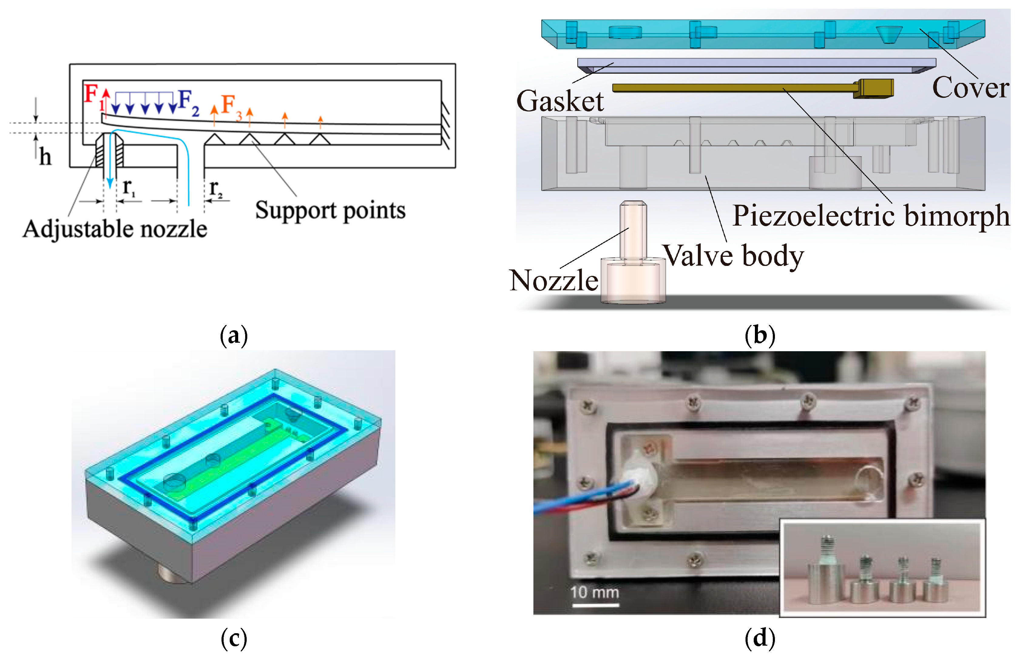
Figure 1. (a) The working principle of the piezoelectric proportional valve; (b) explosion view of the piezoelectric proportional valve; (c) overall structure diagram of the piezoelectric proportional valve; (d) photo of the piezoelectric valve designed and manufactured.
Actuators 14 00463 g001
Figure 2. (a) Streamline diagram with a diameter of 2.4 mm; (b) Stress cloud map at the central cross-section; (c) The influence of outlet diameter on the force and output flow rate at the end of the piezoelectric bimorph under different pressures.
Actuators 14 00463 g002
Figure 3. (a) Diagram of the deflection mechanism of bimorphpiezoelectric bimorph; (b) diagram of deflection mechanism for stacked piezoelectric bimorph (The blue arrow indicates the direction of output force, while the dashed black arrow indicates the direction of deformation or deflection.).
Actuators 14 00463 g003
Figure 4. (a) Output force measurement device for piezoelectric bimorph; (b) displacement measurement device for piezoelectric bimorph; (c) the influence of supporting structure on the output force of piezoelectric bimorph; (d) the influence of the presence or absence of supporting structure on the output force of piezoelectric bimorph.
Actuators 14 00463 g004
Figure 5. Displacement of each point in the Z-axis direction (the direction of L).
Actuators 14 00463 g005
Figure 6. (a) Experimental photos of hardware and gas circuit connections; (b) schematic diagram of component connection method; (c) pneumatic diagram of experimental system.
Actuators 14 00463 g006
Figure 7. (a) Relationship curve between flow rate and pressure (4 types of outlet holes with different diameters); (b) relationship curve between displacement and pressure at the end of the piezoelectric bimorph (4 types of outlet holes with different diameters). (c) Flow characteristic curve and displacement curve of a piezoelectric valve with a nozzle diameter of 2.2 mm under a pressure of 4 bar; (d) flow characteristic curve of VPWS under a pressure of 4 bar.
Actuators 14 00463 g007aActuators 14 00463 g007b
Figure 8. (a) Leakage test with or without adjustable nozzle; (b) electrical power consumption between this work and VPWS; (c) step response curve between this work and VPWS.
Actuators 14 00463 g008
Figure 9. Comparison between this work and the others [11,16,25,30,31,32,33,34,35,36] (The asterisk represents the approximate range of related work performance.).
Actuators 14 00463 g009
Table 1. Model and parameters.
SymbolsParametersValuesUnits
LLength50 (±1)mm
bWidth7.8mm
THeight1.3mm
Driving Voltage200V
Displacement±1000μm
Blocked Force2.6
(With the help of supporting structures)
N
Table 2. Parameters of our valve and the VPWS and VEAE.
ParametersValues:
This Work
Values:
VPWS
Values:
VEAE
Units
Maximum flow rate (4 bar)13018064L/min
Hysteresis rate25.3%8.5%35.9%
Power consumption0.073.960.1 (5 Hz)W
Frequency response<201811Hz
Response time<10<30<40ms
Weight (entirety)14514010g
Weight (actuator)<123<1g
Volume78 × 41 × 1344 × 25 × 42
(Includes manifold block)
63 × 17 × 8mm
Disclaimer/Publisher’s Note: The statements, opinions and data contained in all publications are solely those of the individual author(s) and contributor(s) and not of MDPI and/or the editor(s). MDPI and/or the editor(s) disclaim responsibility for any injury to people or property resulting from any ideas, methods, instructions or products referred to in the content.