Article

Design and Evaluation of a Torque-Controlled Ankle Exoskeleton Using the Small-Scale Hydrostatic Actuator: miniHydrA

by
Kyrian Staman
and
Herman van der Kooij
*
Department of Biomechanical Engineering, University of Twente, 7522 NB Enschede, The Netherlands
*
Author to whom correspondence should be addressed.
Actuators 2025, 14(9), 443; https://doi.org/10.3390/act14090443
Submission received: 27 July 2025 / Revised: 22 August 2025 / Accepted: 3 September 2025 / Published: 8 September 2025
(This article belongs to the Special Issue Control of Hydraulic Robotic Manipulators)

Abstract

A small-scale electro-hydrostatic actuator, termed miniHydrA, was developed based on biomechanical requirements for gait and integrated into an ankle exoskeleton. The key advantage of this actuator concept lies in its compact size and the low mass of its output stage, combined with the ability to deliver high support torques, sufficient for full human assistance. During development, hydraulic cylinder leakage and friction were identified as key challenges. To address control requirements, a dedicated control strategy was proposed and implemented. The prototype exoskeleton was evaluated for joint torque tracking performance across a range of torques (0–120 Nm), both in benchtop tests and during treadmill walking trials. In benchtop experiments, zero-torque tracking was achieved with a mean absolute error ranging from 0.03 to 2.26 Nm across frequencies from 0 to 5 Hz. During treadmill walking, torque tracking errors ranged from 0.70 to 0.95 Nm, with no observable deviations in ankle joint kinematics among the three test subjects. These results show the feasibility of the miniHydrA for remote actuation. Compared to Bowden cables, commonly used in exoskeletons and exosuits, the proposed actuator concept offers two key advantages: it is better suited for high-torque applications, and its friction characteristics can be more accurately predicted and modeled, enabling more effective feedforward control.

1. Introduction

Lightweight design is a critical consideration in the development of wearable devices. This is especially true for assistive technologies that physically support individuals, whether disabled or able-bodied, in performing activities. Such devices must be not only lightweight but also capable of providing controlled, targeted assistance. Active orthoses have been developed to support users in a variety of tasks, often by supporting different limbs depending on the application. Among these tasks, mobility is one of the most essential, and numerous devices have been created to enhance lower limb function, from full-leg exoskeletons [1,2,3] to one degree-of-freedom (DoF) ankle [4,5,6], knee [7,8,9], or hip [10,11,12] exoskeletons. For all wearable assistive devices, minimizing mass offers several key benefits. A lower mass reduces the energy required for the device to move itself, making it more efficient. It also reduces the physical effort needed by the user to handle the device, whether during donning, doffing, or transport. In addition, lightweight devices tend to be more comfortable to wear and often occupy less volume, making them less obtrusive and less likely to interfere with the user or the surrounding environment. Importantly, the location of the added mass relative to the human body plays a critical role. The added mass distally, far from the center of mass of the body, significantly increases the metabolic cost of walking [13,14] and the kinematics of gait [14].
In previous work, we introduced a novel remote actuation concept: the Passive Return Element Hydrostatic Actuator (PREHydrA) [15]. We demonstrated its functionality in a controlled tabletop experiment. The PREHydrA employs an electric motor to drive an input cylinder, using a single fluid line to generate high extension forces at the output cylinder. A passive return element, implemented as a spring mechanism, enables compression forces and prevents the formation of negative pressures within the system.
The PREHydrA operates on the principle of remote actuation, wherein high-mass components are strategically positioned away from the joint to reduce inertia. Forces are transmitted to the joint through a fluidic mechanism, which is conceptually similar to the approach used in Bowden cable actuators [5,16,17,18]. Remote actuation can result in a more favorable mass distribution at the cost of a little added mass with respect to direct joint actuation by linear and rotary electromechanical actuators, as used in [2,9], for example. The absence of valves and other conventional hydraulic components make this hydrostatic actuator more energy efficient (no energy is lost by fluid flow throttling) and transparent (in the sense of lower output impedance) than conventional hydraulic actuation [3,19], while the incompressible fluid transmission does not suffer from the high, non-linear, configuration-dependent friction that sleeved Bowden cables introduce [20]. High friction in Bowden cables not only limits torque control performance but also leads to significant wear, requiring frequent replacement. This further highlights the advantage of the hydraulic approach, which avoids such maintenance issues while maintaining comparable or superior tracking accuracy.
In comparison, other researchers have employed valved hydraulic [3,21,22] and hydrostatic [23,24,25] actuators in wearable devices. These systems consistently demonstrate that small-scale, lightweight hydraulic components, when operated at high pressures, can produce high output torques, resulting in favorable specific torque values (torque-to-mass ratios).
In this work, the output stage of the PREHydrA has been miniaturized through the development of custom, small-scale hydraulic cylinders, referred to as miniHydrA, for integration into an ankle exoskeleton, as illustrated in Figure 1. The ankle joint was chosen due to its high sensitivity to added mass, which significantly affects metabolic cost and gait kinematics [13]. Moreover, the ankle plays a critical role in both gait propulsion [26] and balance control [27]. Normal walking (gait) was selected as the primary use case, given its prevalence in daily human locomotion.
Since the miniHydrA delivers high specific force in a compact form, a strong yet lightweight exoskeleton structure is required to effectively transmit force to the wearer without compromising the benefits of remote actuation. In this study, the input stage was not designed for wearable use; instead, a tethered setup with off-the-shelf components was employed. Compared to our previous work [15], torque tracking performance was improved by implementing a feedforward control strategy that compensates for the identified friction characteristics of both the input and output stages. This enhanced control approach proved necessary and sufficient to accurately track both zero-torque and pulse-wise torque references during walking.

2. Exoskeleton Design

A one-DoF wearable ankle exoskeleton was designed to provide full support during level-ground walking. Based on a sagittal-plane analysis using a rigid body model with hinge joints at the hip, knee, and ankle, and utilizing two gait datasets, Bovi data [28] and Winter data [29], the requirements for the ankle exoskeleton were determined. Since the provided torque data was normalized to total body mass, it was scaled using the average body mass of a Dutch adult (according to the DINED database (average dutch adult, aged 20–60, accesed on 4 June 2018, https://dined.io.tudelft.nl/en/database/tool)), which is 75 kg. An estimated 10 kg was added to account for the mass of the exoskeleton backpack. The walking speed was set to a self-selected, normal pace of 1.22 m/s, as in Bovi et al. [28].
Although the required range of motion for the above tasks (22 plantarflexion to 11 dorsiflexion) is smaller than the average anatomical range of motion of the human ankle joint (approximately 50 plantarflexion to 30 dorsiflexion [30]), the exoskeleton was designed to accommodate the latter. This approach was taken to avoid restricting the wearer’s natural movement, thereby enhancing comfort and ease of use. From the two data sets, the peak plantar- and dorsiflexion joint torques were about 125 Nm and 5.5 Nm, respectively. The peak plantar- and dorsiflexion joint velocities were about 5 rad/s and 2.8 rad/s, respectively, and the peak power required was about 320 W.
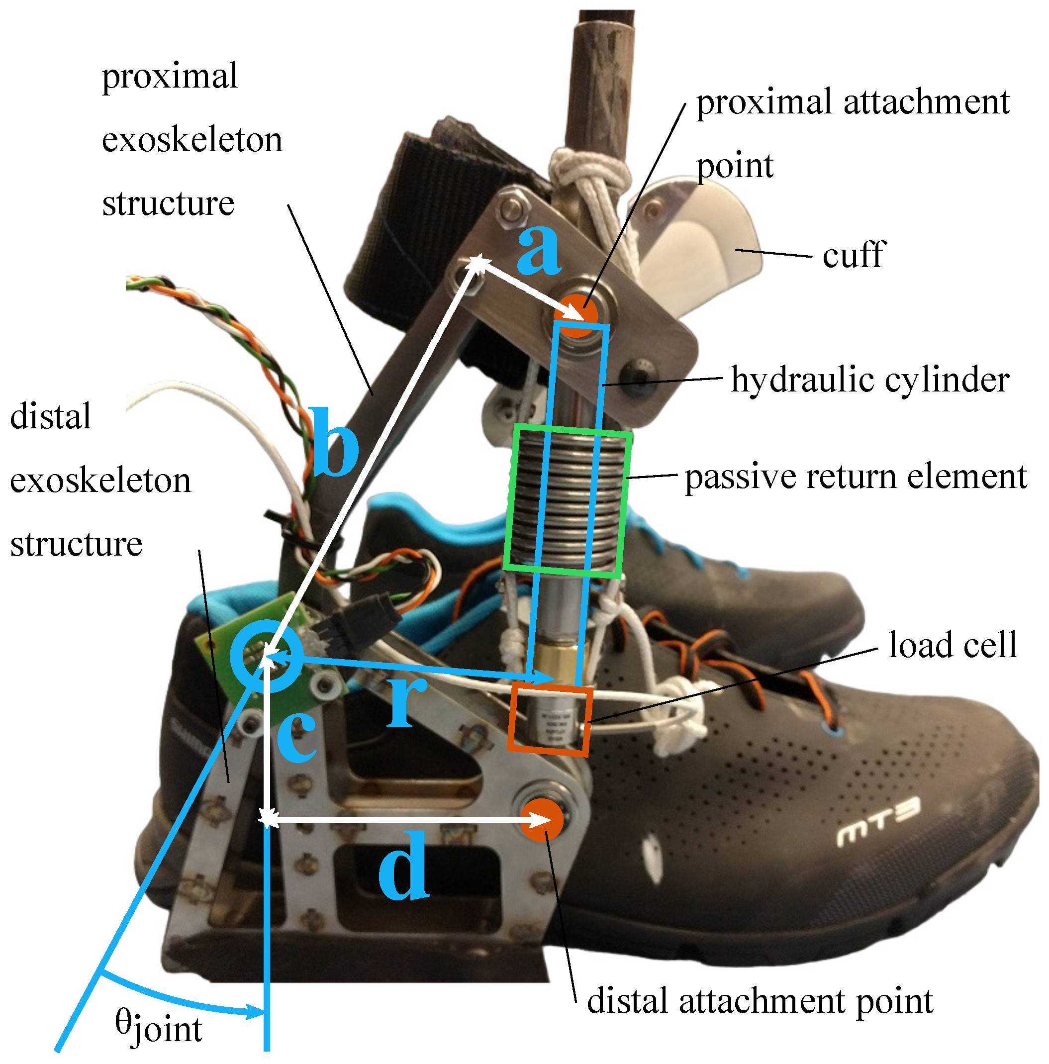
Since the miniHydrA is a translational actuator, a critical design decision was the placement of the actuator, specifically its attachment points relative to the exoskeleton joint. These points largely determine key actuator characteristics such as velocity, pressure, and range of motion, as well as the overall volume and mass of the system. The positioning of these attachment points defines an important parameter of the design: the moment arm (indicated by r in Figure 2).
In general, for most devices that use a translational actuator to generate torque between two moving bodies connected by a revolute hinge joint, the actuator’s moment arm presents a significant trade-off between the required actuator force and velocity. Specifically for hydraulic cylinders, high output forces can be achieved with relatively lightweight components. Additionally, reduced motion leads to lower fluid requirements, smaller overall cylinder volume, and decreased friction, seal wear, and leakage. However, this trade-off results in higher reaction forces within the exoskeleton structure, necessitating a stiffer and more robust design.
In this work, the system was designed to be as compact as possible, positioning it as close to the ankle joint as feasible. The actuator attachment points were selected accordingly, ensuring that the cylinder’s required range of motion fit just within its stroke length, taking into account the cylinder’s “dead length” (see Section 3.3). This was achieved through an iterative process of adjusting both the attachment points and the cylinder design. The final configuration parameters are as follows: a = 25 , b = 105 , c = 45 , and d = 65 mm.
Once the attachment points were defined, the exoskeleton structure was designed with a trade-off between stiffness, strength, and weight. A single revolute joint was used, which was assumed to align sufficiently well with the user’s ankle joint. The distal part of the exoskeleton was attached to the sole of a reinforced shoe, consisting of a carbon fiber-reinforced polymer plate on the inside and a steel plate on the outside. This setup allowed the shoe fabric to distribute forces across the foot. The front of the shoe, beyond the metatarsophalangeal joint, was left unreinforced to enable comfortable toe roll-off during gait. The exoskeleton is shown in Figure 2.

3. miniHydrA Design

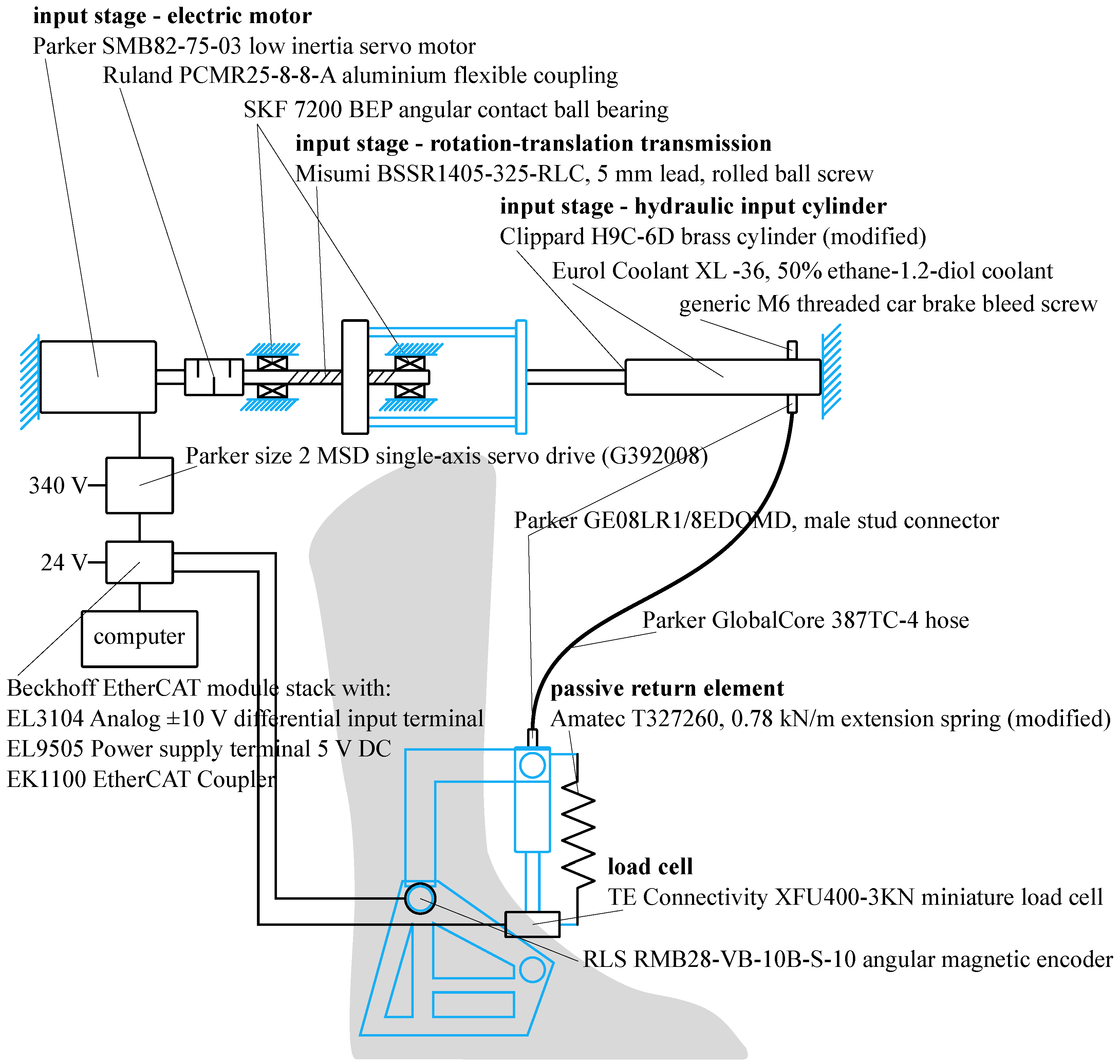
The miniHydrA, like its predecessor the PREHydrA, consists of an electric motor, a rotational-to-translational transmission, an input cylinder, a hose, a miniature output cylinder, and a passive return element, as illustrated in Figure 1. To validate the miniHydrA design, a tethered setup was used in which the input stage, comprising an electric motor, transmission, and an input cylinder, was mounted on a fixed frame (Figure 3).

3.1. Input Stage

The electric motor was selected to be sufficiently powerful, delivering 2 kW of power and a nominal torque of 3 Nm. With the transmission configuration shown in Figure 3, this results in approximately 3.8 kN of force applied to the input cylinder, which translates to about 5.4 kN of output force. The components of the input stage were mounted on an aluminum frame that was fixed to a table.

3.2. Hose

The hose was selected for its high flexibility and low weight, as it needed to be (partially) routed along the wearer’s leg. A length of 3 m was sufficient to connect the input stage cylinder to the output cylinder in the exoskeleton, following the contours of the lower and upper leg. The hose’s maximum pressure rating of 300 bar was adequate for the operating conditions of the miniHydrA system presented in this work.

3.3. Output Cylinder

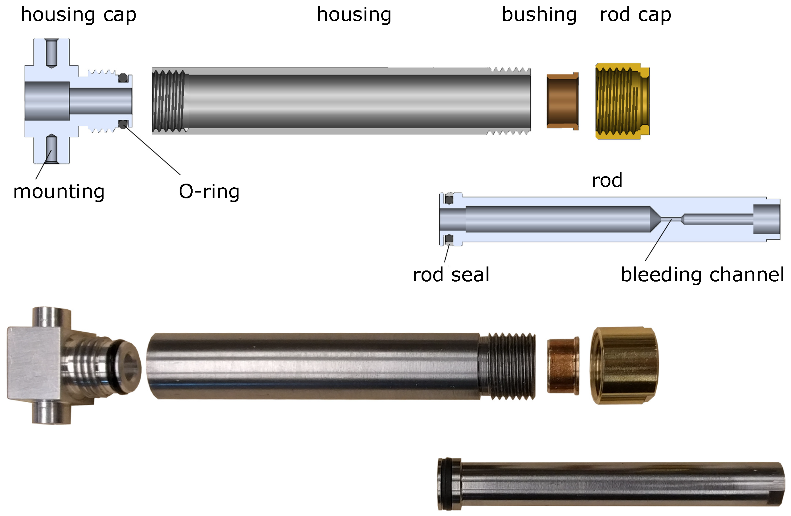
The required range of motion, maximum pressure, and the design objectives of low mass and compact volume fall outside the capabilities of commercially available hydraulic or pneumatic cylinders. In this work, we propose a custom design for a lightweight, compact, high-pressure hydraulic cylinder tailored for use in the miniHydrA system, as illustrated in Figure 4.
The cylinder consists of two main components that move relative to each other via fluid motion: the housing and the (piston) rod. Rod motion is guided at the rod cap, where a single bronze-coated bushing is used to minimize dead length. The separate rod cap enables assembly and secures the bushing in place.
Sealing between the rod and housing is essential to prevent fluid leakage, as these parts move relative to each other. Since the miniHydrA is a unidirectional (single-acting) actuator, a single-acting PTFE rod seal is used. Fluid enters through a commercial connector, which is screwed into the housing cap. This cap also serves as the mounting interface to the exoskeleton’s bearings. A standard O-ring provides a static seal between the housing and cap.
A bleeding channel runs through the rod to release trapped air, sealed by a ball bearing pressed into a conical seat. Finally, the rod end features internal threading for connection to the exoskeleton’s load cell.
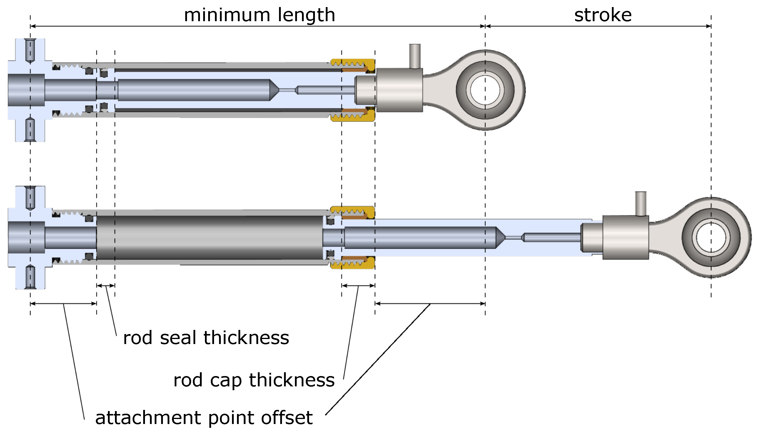
As described in Section 2, the cylinder design both affects and is constrained by the placement of attachment points. A key limitation is the stroke-to-minimum-length ratio, which is reduced by dead length, the combined thickness of the rod cap, seal, and attachment offsets (see Figure 5). This added length increases the minimum cylinder size without contributing to stroke, limiting how close the actuator can be positioned to the joint. The final design includes 62 mm of dead length, with 30 mm due to the load cell, resulting in a stroke-to-minimum-length ratio of 0.5.
Using the configuration parameters and the two gait datasets, the required actuator stroke, velocity, and force were determined. To accommodate the average anatomical range of motion of the human ankle, the actuator must provide a stroke of 60.8 mm. The miniHydrA cylinder meets this requirement with a 61.7 mm stroke. This small margin allows the introduction of built-in hardware end stops, ensuring the exoskeleton cannot exceed the natural joint limits.
For gait, the peak actuator velocities are calculated as 0.24 m/s during cylinder retraction (ankle dorsiflexion) and 0.13 m/s during extension (ankle plantarflexion), relatively low speeds for hydraulic seals.
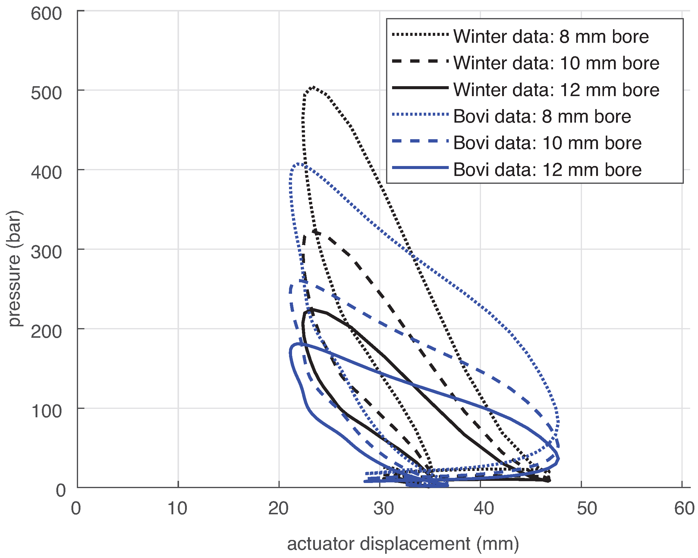
The net force generated by the miniHydrA is the hydraulic cylinder force, produced by pressurized fluid, minus seal friction (fluid friction is neglected based on model analysis) and the opposing force from the passive return element. Since the cylinder is single-acting (extension only), retraction is achieved by storing energy in a spring-based return element. Using the return element design from Section 3.4 and estimated friction from previous work [15], the required cylinder force, and thus pressure, was calculated. Figure 6 shows the required cylinder pressures over actuator displacement for three different cylinder bore sizes.
The 12 mm bore cylinder was selected due to its lower required operating pressures. Pressures above 300–400 bar demand more complex design considerations and specialized components. For the 12 mm cylinder, the required actuator forces range from 31 N to 2618 N, corresponding to pressures between 3 and 232 bar.

3.4. Passive Return Element

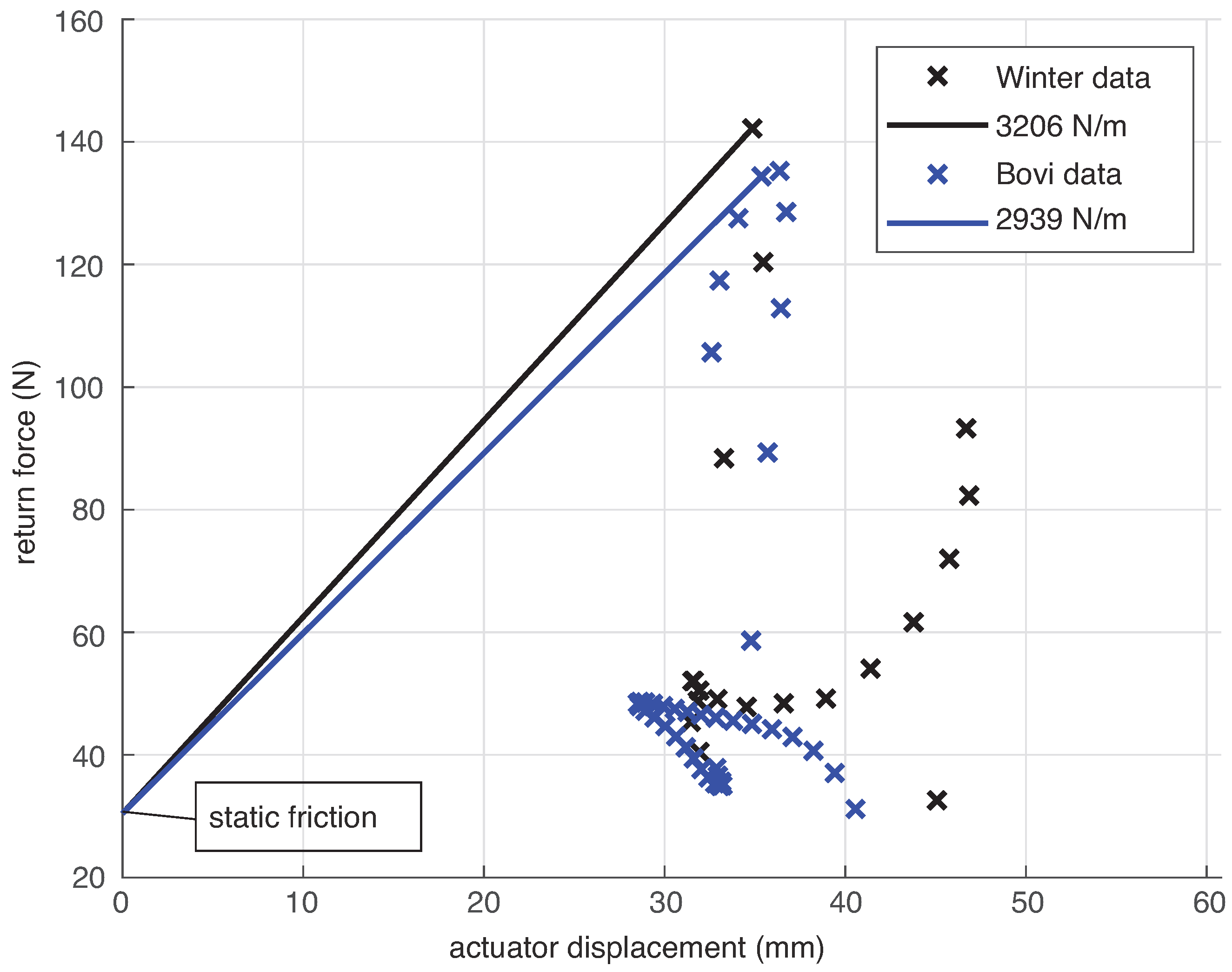
The miniHydrA concept incorporates a passive return element designed to generate a torque profile sufficient for the intended task. In this work, a linear spring is used across the full actuator range of motion. Spring stiffness is derived from the two gait datasets, as shown in Figure 7. The return force corresponds to the negative portion of the required actuator force (producing dorsiflexion torque), plus the static friction of both the input and output cylinders (see Section 5.2).
Applying a return force greater than static friction across the full range of motion ensures that the actuator reliably returns to its retracted position (full dorsiflexion) when not powered. This helps maintain system pressure and prevents air ingress (aeration) during handling.
The required return element stiffness is then determined from the required return force and the known displacement of the return element (derived from gait data joint angle). From Figure 7 it can be seen that an approximate stiffness of 3 N/mm lies between the required stiffnesses of 2939 N/m and 3206 N/m of the Bovi and Winter data, respectively. A stroke of at least 61 mm is required for the return element. Since the spring is mounted around the cylinder (see Figure 2), its inner diameter must exceed the 15 mm cylinder diameter, and its free length must stay within the actuator’s minimum length (90 mm). To keep the design compact, the outer diameter should also be minimized. No commercial spring met all these criteria, so a commercial spring (Amatec T32760, Ø30 mm) with a long stroke was modified by cutting windings to increase stiffness. The resulting return element achieved a stiffness of 3.0 N/mm. Adjustable pretension using Dyneema cords was used to fine-tune performance.
An overview of the most insightful design parameters of the exoskeleton and its actuator are provided in Table 1.

4. Control

Regardless of the specific assistive control strategy (not addressed here), interaction torques between the exoskeleton and wearer must be actively controlled [31]. In this work, the aim was a torque tracking accuracy around 1 Nm. This was considered feasible based on the benchtop torque tracking results as presented in Section 5.3 and seems a good benchmark for comfortable interaction control with wearers of support exoskeletons, based on experience.
First, reference support torques should be tracked with a bandwidth of at least 20 Hz to ensure smooth, responsive gait assistance and to handle disturbances such as ground contact or user-induced movements during donning, doffing, or balance corrections [16].
Second, when no support torque is required, the exoskeleton must still follow the wearer’s motion. Even with zero reference torque, residual interaction torques should be minimized. Low apparent impedance ensures mechanical transparency, enabling natural, unresisted movement.
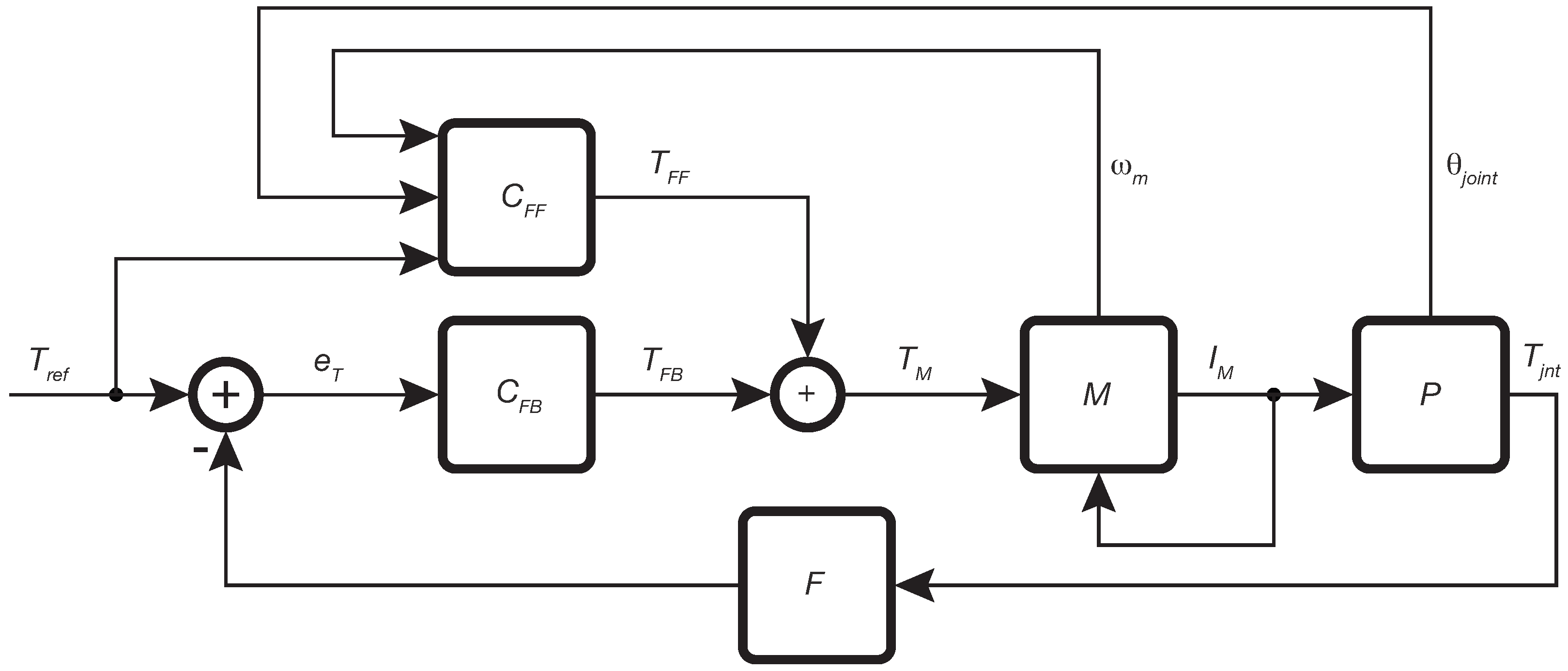
To achieve this, the control strategy shown in Figure 8 has been implemented.

4.1. Feedforward

The feedforward part, C FF , of the controller is used to feed through the joint torque reference, T ref in Nm, to the electric motor by:
T 1 = T ref r i cyl i screw
where r is the moment arm as discussed in Section 2. The transmission ratio, i cyl , is the ratio between the input and output cylinder bore area. The transmission ratio, i screw , arises from the use of a ball screw transmission between the electric motor and input cylinder. In addition, the feedforward is used to compensate the return spring force by calculating the motor torque required to counteract the return force for a given joint angle by using the following equation:
T 2 = ( k ( l ( θ joint ) l 0 ) + F 0 ) i cyl i screw
Furthermore, k is the return element spring stiffness (as discussed in Section 3.4). The actuator length, l, is a function of the joint angle, θ joint , and is determined by geometric analysis based on hinge and actuator attachment points of the orthosis (as shown in Figure 2). Finally, the friction of the input and output cylinders is compensated as follows:
T 3 = F f , in ( v in , p ) i screw T 4 = F f , out ( v out , p ) i cyl i screw
where F f , in ( v in , p ) and F f , out ( v out , p ) are the friction forces in the input and output cylinders, respectively, as functions of their velocities v in , v out and the hydraulic pressure p. These forces are evaluated at the electric motor torque, scaled by the transmission ratios. Section 5.2 details the friction model and its dependence on pressure. In the feedforward controller, this pressure is estimated by the following equation:
p = T ref r A out
The pressure p is estimated from the reference interaction force, calculated as the reference torque T ref divided by the moment arm r and by the output cylinder area A out . The input and output cylinder velocities are derived from the motor’s rotational velocity ω m , obtained from the motor drive M:
v in = ω m i screw v out = ω m i cyl i screw
Note that the cylinder velocities can also be estimated from the measured joint angle. However, the motor drive’s velocity measurement was more accurate and less noisy, so it was used. The feedforward torque T FF is computed by summing all torque components: T 1 , T 2 , T 3 , and T 4 .

4.2. Feedback

The feedback component, CFB, is a finite-derivative serial PD controller acting on the torque error e T , with the following transfer function:
C FB = k p f p f z s + 2 π f z s + 2 π f p
where k p is the proportional gain (0.17), f z is the zero frequency (10 Hz), and f p is the pole frequency (100 Hz). The zero and pole, spaced a decade apart around the 20 Hz bandwidth, provide an approximately 30° phase lead.
The motor torque reference T m is the sum of the feedforward and feedback torques, T FF and T FB , respectively, and is sent to the motor drive. The motor drive uses a high-bandwidth current loop to control the motor current I m , which is part of the plant P. The plant includes the exoskeleton hardware (see Section 2), including the joint encoder that provides the joint angle measurement θ joint . The interaction torque T int is computed from the interaction force measured by the load cell, multiplied by the estimated moment arm derived from θ joint . To reduce noise from both the joint angle and force measurements, and to suppress force spikes due to collisions, the interaction torque estimate is filtered using a first-order low-pass filter F with a cutoff frequency of 20 Hz.

5. Results

Several experiments were conducted to characterize the actuator’s performance. Mechanical properties such as leakage and friction were estimated, plant dynamics were identified, and the control strategy was validated through a zero-torque tracking experiment. Integration into the exoskeleton was tested in two walking experiments: one with minimal impedance and one with support torque tracking.

5.1. Leakage

A simple leakage experiment was conducted in which the miniHydrA cylinder, extended to half stroke, was statically loaded with an 80 kg weight for 72 h. The pressure remained constant at approximately 65 bar, with no observable change in cylinder position.

5.2. Friction Identification

As discussed in Section 4.1, the feedforward controller compensates for friction in both the input and output cylinders. Input cylinder friction was previously identified [32]. Output cylinder friction, specific to the custom miniHydrA cylinder, was identified in a similar manner, by comparing pressure sensor and output load cell measurements, using a modified setup (see Figure 3) in which the hose was replaced with a connector integrating a Measurement Specialties EPXN02150BZ2 pressure sensor. The results are shown in Figure 9. The identified friction model is given by the following equations:
F f = ( F C + F S , 0 e c | v | ) sign ( v ) + f v v F C = F preload + f C p
where F f is the friction force, F C is the Coulomb friction, F S , 0 is the maximum Stribeck force, and F preload is the pressure-independent component of Coulomb friction. The constant c is the Stribeck exponential decay rate, f v is the viscous friction coefficient, and f C is the Coulomb friction pressure coefficient. The friction force depends on velocity v and pressure p. Identified parameters for the input and output cylinders are listed in Table 2.
The Coulomb friction of the miniHydrA cylinder is significantly lower than that of the commercial cylinder—about four times lower in pressure-independent preload and 200 times lower in pressure dependence. Although both cylinders exhibit similar maximum Stribeck forces, the miniHydrA shows a nearly tenfold faster decay rate. As a result, the initial stick-slip effect is comparable (approximately 23 N for the commercial and 17 N for the miniHydrA), but friction in the miniHydrA quickly drops to around 2 N, dominated by F preload . The negative viscous friction coefficient likely results from fitting the model to limited velocity data. Since no significant increase in friction with velocity is observed in the relevant range (0–0.24 m/s, see Section 3.3), viscous friction is assumed to be zero in the feedforward control strategy.

5.3. Benchtop Torque Tracking

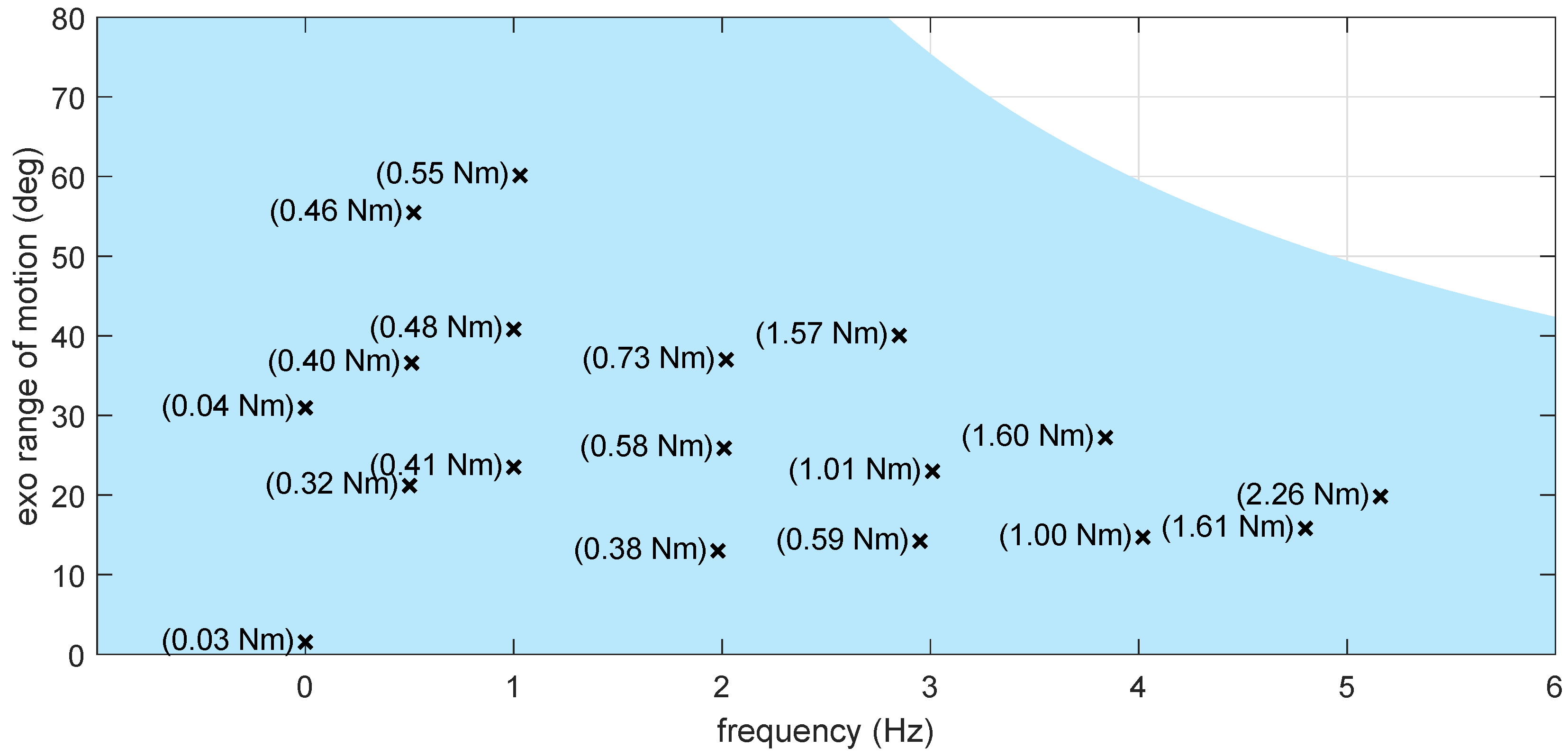
The first two torque tracking experiments measured torque error with the exoskeleton fixed in place, using a dummy foot and lower leg strapped into the device. One experiment was performed with the ankle joint at 0°, and one at −30° (plantar flexion), both controlling zero torque (see 0 Hz experiments in Figure 10).
Sixteen additional experiments were conducted with sinusoidal input motion applied manually to the dummy leg, which had a one-DOF hinge at the ankle. Motion was synchronized to a metronome to maintain consistent frequency and amplitude. Results across various frequencies and amplitudes are shown in Figure 10, where range of motion refers to the peak-to-peak amplitude.
The final experiment involved tracking a series of torque steps (10–120 Nm) with the dummy leg fixed at 0°. Results are shown in Figure 11, with mean absolute errors remaining below 2 Nm for the 120 Nm reference.
The zero torque tracking experiments at 0 Hz (see Figure 10) show the expected load cell measurement noise, and the mean absolute tracking errors at higher frequencies show both an amplitude and frequency dependency (increasing with both). Compared to our previous results [15], the presented control strategy, combined with the small-scale miniHydrA, shows significantly improved tracking performance (3 to 6 times lower errors for the highest range of motion amplitude experiments). This tracking performance is also well maintained for non-zero high torque references.

5.4. Treadmill Walking

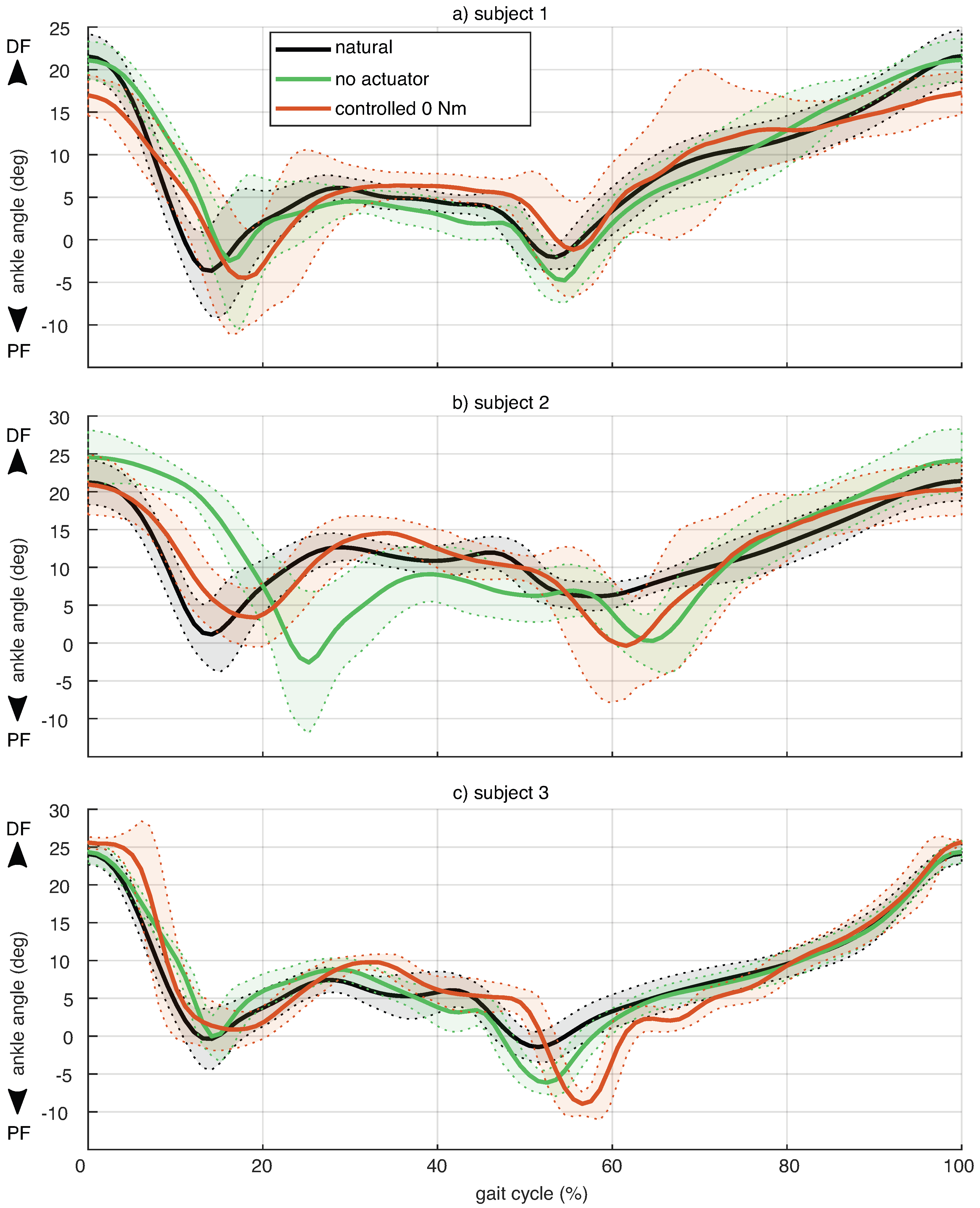
Three able-bodied subjects walked on a treadmill at 1 m/s for approximately 50 steps under three conditions. First, the “natural” condition without the exoskeleton. Second, the “no actuator” condition, with the exoskeleton worn on the right leg but without the miniHydrA, to assess whether the rigid, one-DOF exoskeleton structure affected the ankle joint angle. A negligible difference between the natural and no actuator conditions would indicate that the exoskeleton was sufficiently lightweight and comfortable to allow natural gait. Third, the “controlled” condition evaluated the full system: the exoskeleton with miniHydrA, controlled to track the 0 Nm interaction torque as described in Section 4.
For the natural condition, where no joint encoder was available, the ankle joint angle was estimated using Xsens MVN sensors [33] attached to the feet, lower legs, and upper legs.
Ankle angle data were segmented into individual steps using peak detection and then time-normalized. The average angle and twice the standard deviation for all three conditions are shown in Figure 12. To remove static offsets introduced by strapping the exoskeleton to a bare leg (no actuator condition) or a clothed leg with slight cuff design changes (controlled condition), the average profiles for these conditions were normalized relative to the mean of the natural condition.
The results show no clear deviation in ankle gait patterns when wearing the exoskeleton, either without the actuator (no actuator) or with the controlled miniHydrA system. For Subject 2, a shift in the minimum around 20% of the gait cycle in the no actuator condition suggests a different step size, likely due to the time gap between experiments (several weeks). For Subjects 1 and 2, increased variance in certain gait phases may reflect adaptation to walking with the exoskeleton, as they had less prior experience than Subject 3.
Torque tracking during walking resulted in mean absolute errors of 0.75 Nm for Subject 1, 0.70 Nm for Subject 2, and 0.95 Nm for Subject 3. These errors are higher than those in the 1 Hz, 20° experiments shown in Figure 10, likely due to higher joint velocities during walking compared to the manually applied sinusoidal motions.
Finally, a pilot experiment was conducted with Subject 2 to evaluate non-zero torque tracking during walking with support torque. A TIME profile [34] was applied 0.15 s after heel strike detection, with peak torques of 10, 20, and 40 Nm. Figure 13 shows the reference and measured joint torque for three steps with 40 Nm support. During walking with support torque, the mean absolute tracking error was 0.76 Nm for 10 Nm support, increasing to 0.82 Nm and 1.17 Nm for 20 Nm and 40 Nm support, respectively. These values are consistent with the torque tracking results shown in Figure 10. A large contribution to the torque tracking error is from the phase in between when support is given (as can be seen in Figure 13). This is largely the swing phase of the gait, which starts with toe off and ends with heel contact. At heel strike just before support is given, the controller cannot completely compensate for the rapid changes in joint angle, resulting in a 5 Nm tracking error peak. Directly after the support profile ends, toe off occurs, which is again a rapid change in the system’s dynamics accompanied with rapid changes in joint angle, and torque tracking performance again drops, with peak tracking errors around 4 Nm. Also, the sudden changes in the desired reference support at the begin and end of support contribute to these larger tracking errors at these instances, similar as was observed in the benchtop torque tracking performance (Figure 11).

6. Discussion

The miniHydrA cylinder, described in Section 3.3, is a compact, lightweight hydraulic actuator with a 17 mm outer diameter and a retracted length of 93.7 mm. Weighing just 95 g (as shown in Figure 4), it supports the development of low-volume, wearable actuators. While its actuator strain of 0.7 aligns with typical hydraulic performance [35], the stress output of 15 MPa is relatively low. Due to its high density, the specific stress is approximately 3 kNm/kg.
The passive return element designed for gait, described in Section 3.4, was implemented as a simple tension spring. However, depending on the range of forces encountered in supported tasks and the level of optimization of the return element and actuator system, a more complex solution may be required. Alternatively, the return element could be integrated into the exoskeleton structure itself to provide joint-level return torque.
The controlled treadmill walking experiment described in Section 5.4 resulted in mean absolute torque tracking errors of 0.75 Nm, 0.70 Nm, and 0.95 Nm for the three subjects during zero-torque control. While slightly higher, these values align with the expected performance from the torque tracking experiments in Section 5.3. This also confirms that benchtop torque tracking characterization using manual excitation is a valid method for assessing exoskeleton performance.
The exoskeleton presented in this work (Figure 2) weighs 0.6 kg without the input stage. Of this, 0.2 kg is mounted on the shank, comprising half the hydraulic hose, cuff, exoskeleton structure, and half of the miniHydrA, while the remaining 0.4 kg is on the foot, including 0.1 kg of structure and a 0.3 kg shoe. Comparable cable-driven exoskeletons typically weigh between 0.8 kg [5] and 2 kg [36], depending on system boundaries and included components. This work demonstrates that hydraulic actuation via the miniHydrA can be a viable lightweight alternative. Notably, the main contributors to system mass, the exoskeleton structure and shoe, are actuator-independent and common to all ankle exoskeletons.
Compared to other actuator concepts, the miniHydrA shows strong torque tracking in both benchtop and treadmill tests. A 100 Nm series elastic actuator in zero-torque mode exhibited residual torques up to 1 Nm at 0.1 Hz and 5 Nm at 0.7 Hz [37]. A 72 Nm Bowden cable-driven knee exoskeleton reported a mean absolute tracking error of 0.34 Nm during 60° motion at 0.125 Hz and <0.29 Nm under 24 Nm peak torque conditions [38]. These benchmarks highlight the miniHydrA’s competitive performance, particularly at lower torque levels.
Preliminary torque tracking results from a pilot experiment with one subject are promising. For support torques of 10, 20, and 40 Nm, the root mean square (RMS) errors were 1.1, 1.1, and 1.7 Nm, respectively. In comparison, Witte et al. [5] reported RMS errors of 1.7–2 Nm for full walking trials at 1.25 m/s and 80 Nm support torque using a Bowden cable system. These results suggest that the miniHydrA-based system can achieve comparable tracking performance at lower torque levels.
However, caution is warranted when comparing torque tracking performance across different actuators and exoskeleton systems, as these metrics are influenced not only by the actuator’s torque capacity but also by the specific torque tracking and motion profiles used during evaluation. In general, the benefits of remote actuation for exoskeletons become more manifest for higher torque levels. For lower torques, powerful motors with lower transmission ratios (quasi-direct drives (QDDs)), have been developed that are lightweight and have sufficient torque tracking performance [39,40]. Moreover, pneumatics have also been successfully explored for remote actuation [41] in exoskeleton applications. In the end, the most optimal choice of actuation depends on the specific use case and exact functional requirements. In addition, the torque control performance of the miniHydrA can be further improved for predictable motion patterns, such as periodic gait cycles, through the use of additional feedforward control strategies. One promising approach is iterative learning control, which leverages the repetitive nature of the motion to refine control inputs over successive cycles [42]. This study employed a tethered setup, but for wearable applications, the input stage must be redesigned and optimized for weight and volume. Rather than the double-cylinder configuration used here, a fixed-displacement pump, such as the design proposed by Tessari et al. [43], may offer an alternative.

7. Conclusions

This work presented the design and evaluation of an ankle exoskeleton featuring the miniHydrA actuator, a compact, remote hydraulic actuation concept with an integrated passive return element, offering an alternative to Bowden cables. Its implementation enabled a low-mass, low-volume exoskeleton capable of delivering high support torques. The custom-designed output cylinder demonstrated that small-scale hydraulics can provide significant performance benefits for wearable systems. While friction in the hydraulic cylinder posed a challenge for torque control, this study showed that, with appropriate control strategies, the system can achieve torque tracking performance comparable to state-of-the-art solutions for similar applications.
Overall, the miniHydrA concept demonstrates strong potential for use in wearable technologies and other remote actuation systems that benefit from actuators with high specific force and compact form factors. However, for wearable applications, the input stage must be redesigned, as the current prototype has only been evaluated in a tethered configuration.

Author Contributions

Conceptualization, K.S.; methodology, K.S.; software, K.S.; validation, K.S.; formal analysis, K.S.; investigation, K.S.; data curation, K.S.; writing—original draft preparation and visualization, K.S.; resources, H.v.d.K.; supervision, H.v.d.K.; project administration, H.v.d.K.; funding acquisition, H.v.d.K.; writing—review and editing, K.S. and H.v.d.K. All authors have read and agreed to the published version of the manuscript.

Funding

This research was funded by the Dutch Organisation for Scientific Research (NWO) as part of the Flexible Robotic Suit programme, under grant number 14429.

Data Availability Statement

The raw data supporting the conclusions of this article will be made available by the authors on request.

Acknowledgments

The author’s would like to thank Quint Meinders for the design and manufacturing of the test setup and Michiel Ligtenberg for maintenance and adaptation of the test setup.

Conflicts of Interest

The authors declare no conflicts of interest. The funders had no role in the design of the study; in the collection, analyses, or interpretation of data; in the writing of the manuscript; or in the decision to publish the results.

References

  1. Choi, J.; Na, B.; Jung, P.G.; Rha, D.w.; Kong, K. WalkON suit: A medalist in the powered exoskeleton race of Cybathlon 2016. IEEE Robot. Autom. Mag. 2017, 24, 75–86. [Google Scholar] [CrossRef]
  2. Esquenazi, A.; Talaty, M.; Packel, A.; Saulino, M. The ReWalk powered exoskeleton to restore ambulatory function to individuals with thoracic-level motor-complete spinal cord injury. Amer. J. Phys. Med. Rehabil. 2012, 91, 911–921. [Google Scholar] [CrossRef]
  3. Zoss, A.B.; Kazerooni, H.; Chu, A. Biomechanical design of the Berkeley lower extremity exoskeleton (BLEEX). IEEE Trans. Mechatronics 2006, 11, 128–138. [Google Scholar] [CrossRef]
  4. Galle, S.; Malcolm, P.; Collins, S.H.; De Clercq, D. Reducing the metabolic cost of walking with an ankle exoskeleton: Interaction between actuation timing and power. J. Neuroeng. Rehabil. 2017, 14, 35. [Google Scholar] [CrossRef]
  5. Witte, K.A.; Zhang, J.; Jackson, R.W.; Collins, S.H. Design of two lightweight, high-bandwidth torque-controlled ankle exoskeletons. In Proceedings of the 2015 IEEE International Conference on Robotics and Automation (ICRA), Seattle, WA, USA, 26–30 May 2015; IEEE: Piscataway, NJ, USA, 2015; pp. 1223–1228. [Google Scholar]
  6. Blaya, J.A.; Herr, H. Adaptive control of a variable-impedance ankle-foot orthosis to assist drop-foot gait. IEEE Trans. Neural Syst. Rehabil. Eng. 2004, 12, 24–31. [Google Scholar] [CrossRef] [PubMed]
  7. dos Santos, W.M.; Caurin, G.A.; Siqueira, A.A. Design and control of an active knee orthosis driven by a rotary series elastic actuator. Control Eng. Pract. 2017, 58, 307–318. [Google Scholar] [CrossRef]
  8. Saccares, L.; Sarakoglou, I.; Tsagarakis, N.G. iT-Knee: An exoskeleton with ideal torque transmission interface for ergonomic power augmentation. In Proceedings of the 2016 IEEE/RSJ International Conference on Intelligent Robots and Systems (IROS), Daejeon, Republic of Korea, 9–14 October 2016; IEEE: Piscataway, NJ, USA, 2016; pp. 780–786. [Google Scholar]
  9. Pratt, J.E.; Morse, C.J.; Collins, S.H. The RoboKnee: An exoskeleton for enhancing strength and endurance during walking. In Proceedings of the IEEE International Conference on Robotics and Automation, New Orleans, LA, USA, 26 April–1 May 2004; IEEE: Piscataway, NJ, USA, 2004. [Google Scholar]
  10. Yang, C.; Yu, L.; Xu, L.; Yan, Z.; Hu, D.; Zhang, S.; Yang, W. Current developments of robotic hip exoskeleton toward sensing, decision, and actuation: A review. Wearable Technol. 2022, 3, e15. [Google Scholar] [CrossRef]
  11. Ishmael, M.K.; Archangeli, D.; Lenzi, T. A Powered Hip Exoskeleton with High Torque Density for Walking, Running, and Stair Ascent. IEEE/ASME Trans. Mechatron. 2022, 27, 4561–4572. [Google Scholar] [CrossRef]
  12. Zhang, T.; Ning, C.; Li, Y.; Wang, M. Design and Validation of a Lightweight Hip Exoskeleton Driven by Series Elastic Actuator With Two-Motor Variable Speed Transmission. IEEE Trans. Neural Syst. Rehabil. Eng. 2022, 30, 2456–2466. [Google Scholar] [CrossRef]
  13. Browning, R.C.; Modica, J.R.; Kram, R.; Goswami, A. The effects of adding mass to the legs on the energetics and biomechanics of walking. Med. Sci. Sports Exerc. 2007, 39, 515–525. [Google Scholar] [CrossRef]
  14. Meuleman, J.; Terpstra, W.; van Asseldonk, E.H.; van der Kooij, H. Effect of added inertia on the pelvis on gait. In Proceedings of the 2011 IEEE International Conference on Rehabilitation Robotics, Zurich, Switzerland, 29 June–1 July 2011; IEEE: Piscataway, NJ, USA, 2011; pp. 1–6. [Google Scholar]
  15. Staman, K.; Veale, A.J.; van der Kooij, H. Design, control and evaluation of the electro-hydrostatic actuator, PREHydrA, for gait restoration exoskeleton technology. IEEE Trans. Med Robot. Bionics 2020, 3, 156–165. [Google Scholar] [CrossRef]
  16. Veneman, J.F.; Ekkelenkamp, R.; Kruidhof, R.; van der Helm, F.C.; van der Kooij, H. A series elastic-and Bowden-cable-based actuation system for use as torque actuator in exoskeleton-type robots. Int. J. Robot. Res. 2006, 25, 261–281. [Google Scholar] [CrossRef]
  17. Asbeck, A.T.; De Rossi, S.M.; Holt, K.G.; Walsh, C.J. A biologically inspired soft exosuit for walking assistance. Int. J. Robot. Res. 2015, 34, 744–762. [Google Scholar] [CrossRef]
  18. Williams, J.R.; Cuddeback, C.F.; Fang, S.; Colley, D.; Enlow, N.; Cox, P.; Pridham, P.; Lerner, Z.F. OpenExo: An open-source modular exoskeleton to augment human function. Sci. Robot. 2025, 10, eadt1591. [Google Scholar] [CrossRef]
  19. Su, Q.; Pei, Z.; Tang, Z. Analysis of dynamic characteristics of hydraulic driven system for weight bearing lower limb exoskeleton. J. Phys. Conf. Ser. 2022, 2365, 012011. [Google Scholar] [CrossRef]
  20. Chen, D.; Yun, Y.; Deshpande, A.D. Experimental characterization of Bowden cable friction. In Proceedings of the 2014 IEEE International Conference on Robotics and Automation (ICRA), Hong Kong, China, 31 May–7 June 2014; IEEE: Piscataway, NJ, USA, 2014; pp. 5927–5933. [Google Scholar]
  21. Kim, H.; Seo, C.; Shin, Y.J.; Kim, J.; Kang, Y.S. Locomotion control strategy of hydraulic lower extremity exoskeleton robot. In Proceedings of the 2015 IEEE International Conference on Advanced Intelligent Mechatronics (AIM), Busan, Republic of Korea, 7–11 July 2015; IEEE: Piscataway, NJ, USA, 2015; pp. 577–582. [Google Scholar]
  22. Zhu, J.; Wang, Y.; Jiang, J.; Sun, B.; Cao, H. Unidirectional variable stiffness hydraulic actuator for load-carrying knee exoskeleton. Int. J. Adv. Robot. Syst. 2017, 14, 1–12. [Google Scholar] [CrossRef]
  23. Khazoom, C.; Véronneau, C.; Bigué, J.P.L.; Grenier, J.; Girard, A.; Plante, J.S. Design and control of a multifunctional ankle exoskeleton powered by magnetorheological actuators to assist walking, jumping, and landing. IEEE Robot. Autom. Lett. 2019, 4, 3083–3090. [Google Scholar] [CrossRef]
  24. Yu, T.; Plummer, A.R.; Iravani, P.; Bhatti, J.; Zahedi, S.; Moser, D. The design, control, and testing of an integrated electrohydrostatic powered ankle prosthesis. IEEE/ASME Trans. Mechatron. 2019, 24, 1011–1022. [Google Scholar] [CrossRef]
  25. Neubauer, B.; Durfee, W. Preliminary design and engineering evaluation of a hydraulic ankle–foot orthosis. J. Med. Devices 2016, 10, 041002. [Google Scholar] [CrossRef]
  26. Soo, C.H.; Donelan, J.M. Mechanics and energetics of step-to-step transitions isolated from human walking. J. Exp. Biol. 2010, 213, 4265–4271. [Google Scholar] [CrossRef] [PubMed]
  27. Vlutters, M.; van Asseldonk, E.H.; van der Kooij, H. Lower extremity joint-level responses to pelvis perturbation during human walking. Sci. Rep. 2018, 8, 14621. [Google Scholar] [CrossRef]
  28. Bovi, G.; Rabuffetti, M.; Mazzoleni, P.; Ferrarin, M. A multiple-task gait analysis approach: Kinematic, kinetic and EMG reference data for healthy young and adult subjects. Gait Posture 2011, 33, 6–13. [Google Scholar] [CrossRef] [PubMed]
  29. Winter, D.A. Biomechanics and Motor Control of Human Movement; John Wiley & Sons: Hoboken, NJ, USA, 1990. [Google Scholar]
  30. Siegler, S.; Chen, J.; Schneck, C. The three-dimensional kinematics and flexibility characteristics of the human ankle and subtalar joints—Part I: Kinematics. J. Biomech. Eng. 1988, 110, 364–373. [Google Scholar] [CrossRef] [PubMed]
  31. Baud, R.; Manzoori, A.R.; Ijspeert, A.; Bouri, M. Review of control strategies for lower-limb exoskeletons to assist gait. J. Neuroeng. Rehabil. 2021, 18, 119. [Google Scholar] [CrossRef] [PubMed]
  32. Staman, K.; Veale, A.J.; van der Kooij, H. The PREHydrA: A passive return, high force density, electro-hydrostatic actuator concept for wearable robotics. IEEE Robot. Autom. Lett. 2018, 3, 3569–3574. [Google Scholar] [CrossRef]
  33. Schepers, M.; Giuberti, M.; Bellusci, G. Xsens MVN: Consistent Tracking of Human Motion Using Inertial Sensing; Xsens Technologies B.V.: Enschede, The Netherlands, 2018. [Google Scholar] [CrossRef]
  34. Zhang, J.; Fiers, P.; Witte, K.A.; Jackson, R.W.; Poggensee, K.L.; Atkeson, C.G.; Collins, S.H. Human-in-the-loop optimization of exoskeleton assistance during walking. Science 2017, 356, 1280–1284. [Google Scholar] [CrossRef]
  35. Huber, J.; Fleck, N.; Ashby, M. The selection of mechanical actuators based on performance indices. Proc. R. Soc. Lond. Ser. A Math. Phys. Eng. Sci. 1997, 453, 2185–2205. [Google Scholar] [CrossRef]
  36. Wang, T.-m.; Pei, X.; Hou, T.-g.; Fan, Y.-b.; Yang, X.; Herr, H.M.; Yang, X.-b. An untethered cable-driven ankle exoskeleton with plantarflexion-dorsiflexion bidirectional movement assistance. Front. Inf. Tech. Electron. Eng. 2020, 21, 723–739. [Google Scholar] [CrossRef]
  37. Rampeltshammer, W.; Keemink, A.; Sytsma, M.; van Asseldonk, E.; Kooij, H. Evaluation and Comparison of SEA Torque Controllers in a Unified Framework. Actuators 2023, 12, 303. [Google Scholar] [CrossRef]
  38. Yu, S.; Huang, T.H.; Wang, D.; Lynn, B.; Sayd, D.; Silivanov, V.; Park, Y.S.; Tian, Y.; Su, H. Design and control of a high-torque and highly backdrivable hybrid soft exoskeleton for knee injury prevention during squatting. IEEE Robot. Autom. Lett. 2019, 4, 4579–4586. [Google Scholar] [CrossRef]
  39. Azocar, A.F.; Rouse, E.J. Characterization of Open-loop Impedance Control and Efficiency in Wearable Robots. IEEE Robot. Autom. Lett. 2022, 7, 4313–4320. [Google Scholar] [CrossRef]
  40. Yu, S.; Huang, T.H.; Yang, X.; Jiao, C.; Yang, J.; Chen, Y.; Yi, J.; Su, H. Quasi-Direct Drive Actuation for a Lightweight Hip Exoskeleton With High Backdrivability and High Bandwidth. IEEE/ASME Trans. Mechatron. 2020, 25, 1794–1802. [Google Scholar] [CrossRef] [PubMed]
  41. Ma, Z.; Wang, Y.; Zhang, T.; Liu, J. Reconfigurable Exomuscle System Employing Parameter Tuning to Assist Hip Flexion or Ankle Plantarflexion. IEEE/ASME Trans. Mechatron. 2025, 1–12. [Google Scholar] [CrossRef]
  42. Zhang, J.; Cheah, C.C.; Collins, S.H. Experimental comparison of torque control methods on an ankle exoskeleton during human walking. In Proceedings of the 2015 IEEE International Conference on Robotics and Automation (ICRA), Seattle, WA, USA, 26–30 May 2015; pp. 5584–5589. [Google Scholar] [CrossRef]
  43. Tessari, F.; Galluzzi, R.; Tonoli, A.; Amati, N.; De Michieli, L.; Laffranchi, M. Knee prosthesis powered by a fully integrated and highly back-drivable electro-hydrostatic actuator. Mechatronics 2023, 91, 102972. [Google Scholar] [CrossRef]
Figure 1. Remote ankle actuation, using the miniHydrA concept. The hydrostatic transmission enables remote actuation of the ankle joint. The various components of the output stage as integrated in the ankle exoskeleton are shown in close-up.
Actuators 14 00443 g001
Figure 2. Photo of the exoskeleton with the most important components labeled. Attachment points (red) of the actuator with respect to the joint (blue). The configuration parameters a and b of the proximal attachment point, the parameters c and d of the distal attachment point, and the joint angle, θ joint , determine the moment arm, r.
Actuators 14 00443 g002
Figure 3. Schematic of miniHydrA exoskeleton prototype. Since in this study the exoskeleton was evaluated in a tethered setup, only the output design was optimized but no attempt was made to minimize the mass and dimensions of its input stage. Commercially available components are labeled.
Actuators 14 00443 g003
Figure 4. Top: Annotated drawing of miniHydrA components. Cross-sectional view shows the internal design of the components. Bottom: Photograph of miniHydrA components.
Actuators 14 00443 g004
Figure 5. Cylinder dead length between the exoskeleton attachment points. The load cell is included in the attachment point offset on the rod side.
Actuators 14 00443 g005
Figure 6. Required cylinder pressures as a function of the displacement of the actuator for three cylinder bores, in order to deliver a reference torque profile. The reference torque profile and actuator displacement can be derived from the two gait data sets.
Actuators 14 00443 g006
Figure 7. Determination of the return force requirement. The return element (represented by lines) is selected such that the elastic return force it generates consistently exceeds the required return force (indicated by stars), which is determined from experimental nominal ankle torques as obtained from two different gait data sets, across the entire actuator displacement range. The determined required stiffness (the slopes of the lines) of the elastic return element is slightly higher when the Winter dataset is used.
Actuators 14 00443 g007
Figure 8. Interaction torque control block diagram. The C F F , C F B , M, P, and F components are the feedforward controller, feedback controller, motor drive, plant, and filter, respectively.
Actuators 14 00443 g008
Figure 9. Friction experiments and fitted model results for the miniHydrA output cylinder. The cylinder was driving at a constant velocity, and the difference between the input and output force was used to estimate the friction force as in [32].
Actuators 14 00443 g009
Figure 10. Benchtop results. The ankle exoskeleton was attached to a dummy foot and lower leg connected by a hinge joint. The foot was attached to the ground while the lower leg was manually held in place or sinusoidally moved. Mean absolute errors (numbers within parenthesis) during zero-torque tracking were estimated from force and angle measurements. The range of motion represents the peak-to-peak amplitude of manually applied joint movements at different movement frequencies. Reference signals at 0 Hz correspond to static joint angles of approximately 0° and 30°. The shaded blue region indicates the actuator’s operational range, constrained by the physical end stops of the test setup and the maximum motor velocity.
Actuators 14 00443 g010
Figure 11. Benchtop torque control tracking performance. The dummy foot and lower leg, to which the exoskeleton was attached to, were fixated to constrain ankle joint rotation. For a series of torque steps up to 120 Nm, the reference and measured dorsiflexion (DF) and plantarflexion (PF) joint torque (top) and the error between reference and measured torque (bottom) are shown.
Actuators 14 00443 g011
Figure 12. Mean and twice the standard deviation of the right ankle joint angle during walking at 1 m/s under three conditions: (1) natural walking without the exoskeleton, (2) walking with the exoskeleton but without the miniHydrA actuator, and (3) walking with the active exoskeleton in zero-torque tracking mode. Time is normalized to the gait cycle. Dorsiflexion (DF) and plantarflexion (PF) directions are indicated for reference.
Actuators 14 00443 g012
Figure 13. Reference support torque (black) and measured exoskeleton torque (blue) during walking at 1 m/s, shown over three consecutive steps with a maximum support torque of 40 Nm. Dorsiflexion (DF) and plantarflexion (PF) directions are indicated.
Actuators 14 00443 g013
Table 1. Design parameters.
ParameterValue
proximal attachment distance, a25 mm
proximal attachment distance, b105 mm
distal attachment distance, c45 mm
distal attachment distance, d65 mm
moment arm, r15 to 68 mm
actuator minimum length (including load cell)120 mm (of which 62 mm dead length)
output cylinder stroke61.7 mm
output cylinder inner diameter12 mm
output cylinder forces31 to 2618 N
output cylinder pressures3 to 232 bar
return element stiffness3 N/m
Table 2. Identified friction parameters.
ParameterCommercial Input Cylinder (Standard Deviation)miniHydrA Output Cylinder (Standard Deviation)
F preload 8.1 ( 0.91 ) N 1.82 ( 0.37 ) N
f C 4.2 × 10 6 ( ) N / Pa 2.20 × 10 8 ( ) N / Pa
F S , 0 15.3 ( 5.96 ) N 15.0 ( 18.0 ) N
c 118.5 ( 61.1 ) s / m 1012 ( 887 ) s / m
f v 59.5 ( 3.56 ) Ns / m 8.61 ( 1.97 ) Ns / m
Disclaimer/Publisher’s Note: The statements, opinions and data contained in all publications are solely those of the individual author(s) and contributor(s) and not of MDPI and/or the editor(s). MDPI and/or the editor(s) disclaim responsibility for any injury to people or property resulting from any ideas, methods, instructions or products referred to in the content.