1. Introduction
As important engineering machinery equipment, truck cranes have an irreplaceable role in modern industry, construction, and logistics with their strong load-lifting capacity [
1,
2,
3]. As a crucial part of the truck crane, the level condition and stability of the vehicle-mounted platform are prerequisites for ensuring the lifting capacity and safety of operation [
4,
5,
6,
7]; these can be improved based on fast and coordinated control of the outrigger. Therefore, it is necessary to study the leveling system to improve the operational efficiency, stability, and safety of the crane.
The leveling of crane outriggers currently mainly relies on manual operation and is not yet fully automated. Current studies in this field predominantly concentrate on the vehicle suspension system and small leveling equipment. For instance, Sun et al. [
8] developed an adaptive fuzzy sliding-mode controller (FSMC), achieving high-precision height control of the suspension system under varying payloads and parameter discrepancies, reducing peak attitude angles, and suppressing oscillations significantly. Li et al. [
9] proposed a leveling control method for small leveling equipment based on repetitive positioning, achieving precise leveling for vehicle-mounted theodolites and unloaded outriggers. Although the aforementioned leveling methods can achieve rapid, precise, and reliable leveling of different devices, they are unable to meet the requirements of crane automatic leveling owing to the weak outrigger problem (the outriggers do not bear force or bear little force) and dynamic coupling effects among outriggers. Specifically, as the core issue in crane leveling control, the weak outrigger problem needs to be solved to avoid the risk of crane overturning. On the other hand, the substantial mass of the crane induces an intense dynamic coupling effect among outriggers during leveling. To address these problems, scholars have begun to improve the leveling performance by adopting synchronous leveling control [
10,
11], achieving global synchronous drive through constructing a coupling model. Owing to its outstanding potential in fully accounting for coupling relationships and the simple structure of the control, a synchronous leveling control strategy is implemented in this paper to enhance the leveling accuracy and speed of the crane.
The aforementioned synchronous leveling control methods focus primarily on the coordination and adjustment of outrigger displacement while neglecting the interaction force between the outriggers and the ground [
12]. Notably, an individual outrigger actuator with sustained overload may severely impact the operational efficiency and structural safety of the electric cylinder on it [
13]. To overcome this problem, some scholars have studied related explorations in the field of position–force cooperative control in the last few years. For instance, Wang et al. [
14] designed a dual-loop attitude control system, where the outer loop achieves automatic leveling and the inner loop realizes force tracking to achieve smooth leveling of the tracked tractor’s body. Wu et al. [
15] developed an optimal load distribution algorithm based on attitude leveling, whose effectiveness was validated on multi-axle low-speed vehicles. However, the significant structural variations of the crane, the complex working conditions, and the severe load fluctuations make it difficult to quantify the change of outrigger load caused by the variation in the outrigger position, which results in existing methods being unable to adapt to outrigger load control effectively. Furthermore, as a typical underactuated system [
16,
17], unknown disturbance, multivariable coupling caused by high-order interactions [
18], and model uncertainties [
19] have a harmful influence on leveling control, but the existing synchronous leveling control methods are unable to deal with these problems effectively.
Recently, benefiting from its unique integrated architecture of prediction, optimization, and feedback, model predictive control (MPC) possesses the strong ability of multi-variable optimization and anti-interference capabilities. Meanwhile, MPC has the flexibility to set model constraints and custom optimization weights. Therefore, compared with other control methods, MPC is more likely to achieve high-precision control while maintaining strong robustness, and this shows a significant potential in multi-variable coupling systems with disturbances such as the cranes. Secondly, when facing the complex nonlinear problems and system uncertainties that occur during the operation of the cranes, fuzzy control methods such as the Mamdani type, T-S type, or data-driven type are adopted. The nonlinear and uncertainties are handled through language or mathematical rules [
20,
21], updating the weight distribution between outrigger displacement and the load dynamically. This process can achieve real-time optimization of the load constraints and further enhance the robustness of the control system.
In conclusion, aiming at the specific requirements for the synchronous leveling of crane outriggers and their load constraints, a synchronous leveling control method with variable load constraints (SLCM-VLC) is designed in this paper. It has a three-layer progressive control architecture built upon dual-layer model predictive control, which takes full consideration of the decoupling synchronization, dynamic weighted collaboration, and disturbance compensation [
22]. The main contributions of this paper lie in the following aspects: (1) The coupling outriggers are modeled and decoupled independently through adjacent cross coupling. Based on which, a displacement synchronization controller (DSC) is implemented to achieve efficient synchronous leveling of the four-outrigger platform. (2) Based on the proposed SLCM-VLC method, a collaborative controller of displacement and force (DFCC) is designed to achieve the co-optimization of synchronization precision and outrigger force constraint, in which fuzzy control theory (FC) is used to dynamically update the weight of the outrigger load term, overcoming the limitation of traditional strategies that rely on independent optimization. (3) An extended state observer (ESO) is designed to compensate for control deviations caused by environmental disturbances and inaccuracies of the dual-layer MPC model. (4) Comprehensive simulations of the crane outrigger platform are conducted to verify the effectiveness of the proposed method based on the co-platforms of Soildworks, Adams, and Matlab. The experiment results demonstrate that the proposed method not only realizes fast and smooth synchronous leveling of crane outriggers but also improves the service life of the electric cylinder on the outrigger.
The structure of the rest of this paper is as follows.
Section 2 models the four-outrigger support platform and leveling mechanism of the crane. In
Section 3, the SLCM-VLC method is proposed, and then the DSC, DFCC, and ESO are designed in turn.
Section 4 conducts a multi-domain joint simulation and results analysis.
Section 5 summarizes the work of this paper.
2. Modeling of Four-Outrigger Support Platform
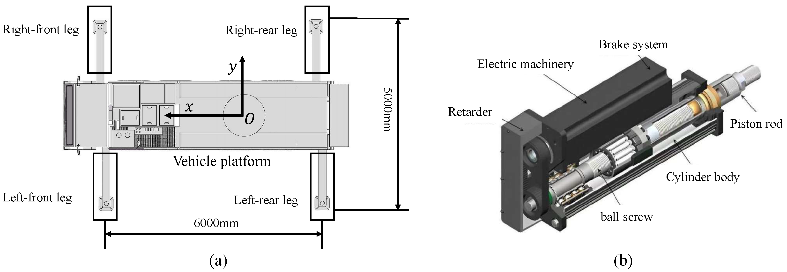
The three-dimensional model of the truck crane platform is shown in
Figure 1a, which consists of vehicle body and outriggers symmetrically arranged at four corners. It can be seen that a rectangular support surface with transverse span of 5000 mm and longitudinal span of 6000 mm is formed based on four outriggers. The leveling and lifting functions of the platform are realized through the electric cylinder integrated in each outrigger.
Figure 1b illustrates the internal structure of the outrigger electric cylinder, comprising four primary components: the driving mechanism, the deceleration device, the transmission mechanism, and the cylinder body. The drive mechanism generates rotational power through a surface-mounted permanent magnet synchronous motor (PMSM), while the output torque is amplified through a reduction gearbox. Subsequently, the transmission system converts this rotary motion into linear displacement via a ball screw mechanism, thus enabling telescopic actuation of the outrigger. An accurate mathematical model is the foundation for high-precision leveling control of the crane. Thus, the model of the PMSM and electric cylinder are introduced in the following Sections.
2.1. Mechanism Modeling of Four-Outrigger Support Platform
As the key control variable for the leveling controller, the displacement calculation of each outrigger is the basis for the control strategy design. Therefore, the theory of attitude change and the highest point horizontal measurement method are adopted to calculate the leveling displacement required for the outriggers [
23].
To facilitate the calculation and analysis, the truck crane is simplified as a four-outrigger support platform with length of
L and width of
b. Furthermore, the platform is regarded as being rigid, and the symmetry center of the platform is taken as the origin
O. Thus, the rotation diagram of the four-outrigger support platform in a Cartesian coordinate system are shown in
Figure 2.
With the rotation of the platform, inclination angle is composed of pitch angle
around the
x-
and roll angle
around the
y-
. Suppose that when the outrigger platform is tilted, the position of point
P on the platform changes from
to
, which can be obtained according to the theory of attitude change.
Since leveling only considers the vertical displacement, the coordinates of each outrigger in the
x-
y plane are substituted into Equation (
2). Consequently, the vertical displacement
(
) for each support outrigger can be obtained as follows:
After calculating the vertical displacement of each outrigger, various leveling approaches can be implemented, including the highest point chasing method, the lowest point chasing method, and angle error control leveling method. In this paper, the highest point chasing method with unidirectional extension is applied. Assuming the fourth outrigger represents the highest point, the corresponding momentum of each outrigger is obtained, as displayed in Equation (
3):
2.2. Mechanical Model of Electric Cylinder
As the driving source of the outrigger electric cylinder, the following assumptions are made for the PMSM to facilitate modeling and analysis:
(1) Magnetic circuit saturation, eddy current, and hysteresis loss are ignored.
(2) There is no damping winding or damping effect in the rotor and the permanent magnet, respectively.
(3) The back EMF of the motor is sinusoidal, and the distributed magnetomotive forces generated by stator currents in the air gap are also sinusoidal. Thus, the high-order harmonics of the magnetic field should be ignored.
Based on the above assumptions, the mathematical model of the PMSM in the
d-
q rotating coordinate system is obtained as follows [
24,
25]:
where
is the mechanical angular displacement of the motor,
is the mechanical angular velocity,
represents the electromagnetic torque,
B indicates the viscous friction coefficient,
is the load torque,
J is the rotor moment of inertia,
and
denote the stator voltages of the
q-
and
d-
, respectively,
and
are the stator current under the
d-
q,
and
represent the inductance under the rotating coordinate system in the
d-
q frame,
R is the stator resistance,
indicates the pole pair, and
is the permanent magnet flux linkage.
Owing to the neglect of magnetic saliency effects in the surface-mounted PMSM, the
d-
and
q-
inductance satisfy
. Consequently, there is no reluctance torque component, and the electromagnetic torque
is generated solely by the permanent-magnet flux linkage with the current component
, as defined in Equation (
8). In addition, the reference of the
d-
current is usually set to zero (
) in the
d-
q frame, except in the field-weakening region. Given a well-designed current controller,
is expected to follow
. Under these assumptions,
can be approximated by Equation (
8):
Combining Equation (
4) and Equation (
8), the speed of the motor can be obtained as follows:
The angular velocity output by the motor serves as the input of the mechanical transmission part, and the actual displacement
of the electric cylinder is the output of the mechanical transmission part. As a result, the electric cylinder can be modeled as follows:
where
is the reduction ratio of the reducer,
indicates the angular velocity of the screw,
p represents the lead of the screw,
and
are the output speed and output displacement of the electric cylinder, respectively.
and
represent the starting time and stop time of the electric cylinder.
2.3. Collaborative Model of Four-Outrigger Support Platform
The crane outriggers are driven by the electric cylinder installed on each of them, realizing the extension and contraction movement. Combining Equation (
4) and Equations from Equation (
7) to Equation (
12), it is obvious that the angular velocity output by the motor serves as the input of the mechanical transmission part. The mathematical model of the entire electric cylinder is established through integrating the motor and the mechanical transmission, and the state equation of the system is integrated as follows:
where
The kinematic equation of the whole crane platform is obtained by combining the four electric cylinders.
where
are the coefficient matrix of each electric cylinder state equation.
To facilitate calculation and analysis, the continuous motion model of the outriggers presented in Equation (
15) can be abstracted as follows:
where
x is the state vector,
u is the action vector, and
f is the dynamic function of the electric cylinder.
Due to outstanding forecast performance of MPC, the SLCM-VLC controller designed in this paper is constructed based on the frame of it. Owing to the inherent characteristics of the MPC, which is exclusively applicable to discrete systems, it is necessary to discretize the continuous system. Thus, the discretized equation can be obtained using the forward ruler method.
where
k represents the value of the current moment,
is the discrete time step,
and
are the corresponding coefficient matrix of
and
, respectively,
E is unit matrix.
Then, in order to achieve the cooperative of the displacement–force dynamic, the Equation (
17) can be augmented with electromagnetic torque, and the collaborative modeling of the four-outrigger support platform is completed as follows:
At the discrete-time step
k > 0, based on the Equation (
19), the derivation of the MPC’s prediction of the future state and output variables of the system in the prediction time domain is as follows:
By organizing Equation (
20), the prediction model of MPC can be obtained as
3. Design of Synchronous Leveling Control Strategy
3.1. Overall Structure of SLCM-VLC Control Strategy
Following the collaborative model construction in
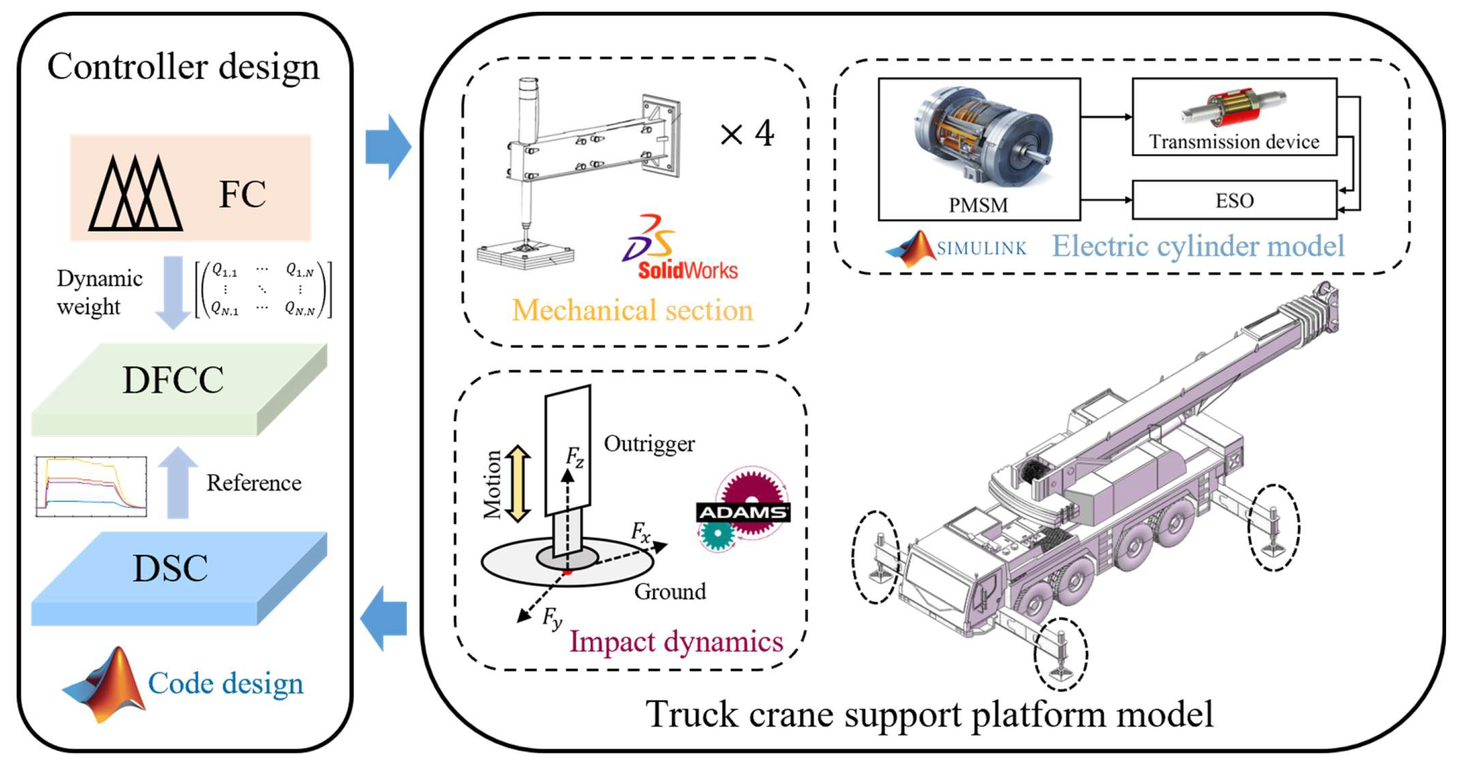
Section 2, a SLCM-VLC control strategy based on the MPC frame is proposed. This strategy incorporates a multi-step prediction and rolling optimization mechanism, aiming to enhance dynamic response performance and anti-interference capabilities. In the design phase, the inclination angle of the vehicle platform, the synchronization error among outriggers, the load variation of the outriggers, and the dynamic performance of the electric cylinder are considered as the core indicators and input parameters to co-optimize outrigger position–force performance. The overall structure is shown in
Figure 3.
It can be seen that the SLCM-VLC consists of three parts: displacement synchronization controller (DSC), collaborative controller of displacement and force (DFCC), and compensation scheme of uncertainty-oriented outrigger (CSU). The DSC is applied to deal with the synchronization problem of the crane outrigger displacement with consideration of the adjacent cross-coupling relationships among the four outriggers. And the DFCC achieves the coordination of the outrigger load and position through updating the weight dynamically. Moreover, the ESO is introduced in the CSU to compensate the modeling error and the external uncertainty of the crane outrigger platform.
3.2. Displacement Synchronization Controller
As mentioned in
Section 2, a synchronous leveling control strategy based on adjacent cross-coupling is implemented in this paper to enhance the leveling accuracy and speed of the crane. The core principle of adjacent cross coupling control is that coupling errors are derived from position error. As a result, a synchronization cost function that integrates coupling errors is designed to convert the ideal displacement of the outriggers into a matching synchronous reference velocity, providing a reference for the collaborative optimization of the DFCC. The optimization objectives mainly include the synchronization error among the platform’s outriggers and the variation increment of the control input so as to ensure the synchronous leveling and smooth operation of the system. The specific design of the cost function in displacement synchronization controller is introduced as follows:
Firstly, considering the tracking accuracy of the outriggers to the ideal displacement
, the cost function is designed accordingly to minimize the cumulative tracking error in the prediction time domain.
where
is the prediction time domain,
i represents the future time domain,
is the weight matrix of the trajectory tracking error, and the maximum value of
is set to 610 mm.
Then, the reference trajectory is matched with the velocity of the reference on the basis of the cross-coupling. Unlike the conventional synchronization strategies that track with the same displacement, the ideal telescopic displacement of each outrigger is usually different during the leveling process. Therefore, the synchronous control methods based on the same displacement setting value cannot be directly adopted. For this reason, a synchronization cost function based on relative displacement is designed in this paper.
where
is the weight coefficient matrix of the corresponding outrigger synchronization.
Finally, in order to ensure the stability and smoothness of trajectory tracking and outrigger synchronization, it is necessary to consider the variation in the control input
u. The cost function of the variation in the control input is designed as follows:
where
is the control time domain,
R is the weight coefficient matrix of the control.
By combining the equations from Equation (
22) to Equation (
24), the cost function for the displacement synchronization controller is formulated as
In a word, there is a novel attempt in the design of cost function for the displacement synchronization controller that incorporates adjacent cross-coupling relationships among the four outriggers. Based on the displacement synchronization controller, the ideal displacement of the outrigger is converted into a synchronous reference speed () through using the Quadprog solver under the constraints of motor parameters and cost function. As a result, the leveling control of the four outrigger displacements is achieved.
3.3. Collaborative Controller of Displacement and Force
Based on the synchronous reference speed obtained from the displacement synchronization controller, this section focuses on position–force coordination and the increment change of the control input as the optimization objectives of the MPC. A collaborative controller is constructed to achieve the coordination of displacement and force. Specifically, a novel cost function which integrates position errors and force constraint terms is constructed, whose design process is summarized as follows.
Firstly, a collaborative cost function in Equation (
26) is constructed by integrating the outrigger load optimization term to dynamically coordinate the position synchronization and the load distribution of the outriggers. This improves the performance of the electric cylinder of the crane outriggers, such as service life, load distribution, etc.
where
is the output matrix,
F is the terminal weight matrix, and
Q is the variable weight matrix, which is divided into speed
and torque
.
Furthermore, in order to balance the maximum load variation and synchronization effect among outriggers dynamically, and combined with the actual requirements of the crane, the rule design of the fuzzy controller should be directly based on engineering experience or experimental data [
21]. This approach provides the intuitive mapping between the load variation and the weight adjustment and reduces the dependency on precise system models to ensure real-time performance. Therefore, this paper employs a real-time and reliable Mamdani fuzzy controller, which contrasts with the complex rule design and strong dependence on mathematical models [
20] of the T-S fuzzy controller, as well as the adaptive fuzzy controller that requires online computing resources [
20]. The dynamic calculation of the variable weight
Q is achieved through this fuzzy controller.
In the designed fuzzy controller, the difference
e between the actual and ideal outrigger output torque, along with its change rate
, are taken as the two inputs. The weight adjustment factor of the motor torque is set as the output. The fuzzy sets for input and output are defined as NB (negative large), NM (negative medium), NS (negative small), PS (positive small), PM (positive medium), and PB (positive large). Although the inputs and output are non-negative, the fuzzy rules are retained for convenience. The specific fuzzy rules are shown in
Table 1.
Considering the complexity of the dynamics of each outrigger during the leveling process, the Gaussian membership functions with high accuracy and strong adaptability are adopted for both input and output. Based on the fuzzy control rules formulated in
Table 1, the designed input and output membership functions are shown in
Figure 4.
According to the designed fuzzy rules and membership functions, for each rule (if
is
,
is
, then
y is
), the activation degree is calculated as
where
c and
are the center and standard deviation of Gaussian function, respectively, and
represents the activation strength of the fuzzy rules.
denotes the membership degree of the output variable
y to the fuzzy set
B.
Using the centroid method for defuzzification, the control output
can be obtained as follows:
Owing to the physical limitations of the electric cylinder outriggers in the leveling process, it is also necessary to set boundary limits on the maximum speed, speed increment, current amplitude, and current increment of the electric cylinder motor. The constraints on control quantity and control quantity increment are constructed as follows:
where
,
are the lower limit and upper limit of the control quantity, respectively, and
,
indicate the lower and upper limits of the control increment, respectively.
Finally, under the constraints of actual physical conditions, the final control values () at the time of k are output based on collaborative controller, realizing the coordination of the outrigger’s load and the position.
3.4. Compensation Scheme of Uncertainty-Oriented Outrigger
To compensate for control deviations caused by external environmental disturbances and inaccuracies in the dual-layer MPC model, an ESO is designed.
As shown in
Figure 5, the modeling error and the external disturbance are regarded as the total disturbance for real-time estimation and dynamic compensation, and the ESO can observe the displacement output of each outrigger electric cylinder. Then the control signals of the motor current are obtained and integrated with the compensation amounts (
). Finally, accurate control of the electric cylinder is driven through the motor space vector pulse width modulation (SVPWM), realizing the telescopic movement of the outriggers.
According to the equations from Equation (
12) to Equation (
14), the state vector of the ESO is defined as
. The total disturbance is considered as an extended state
. At the same time, assuming the extended state is bounded and differentiable, the expression of the electric cylinder can be written as
where
b is the action gain coefficient,
is the transmission coefficient of the electric cylinder transmission device, and
.
f represents the total disturbance, including the deterministic term
, internal dynamics
, and external disturbance
.
Then, ESO is accordingly designed as
where
e is the output estimation error.
are the observed values of
, respectively.
are the three gain coefficients of the observer, and
is a nonlinear function to suppress errors, whose expression is
where
is the nonlinear index, which controls the degree of nonlinearity, and
is the thickness of the boundary layer for switching.
Regarding the stability of the proposed controller, the analytical approach in [
26] is adopted. Firstly, the stability of MPC is rigorously guaranteed through well-documented theoretical proofs. Then, the fuzzy control is used to update the weight value
[0, 1] in the cost function, and the weight update is adjusted by the control target. This dynamic update method does not change the positive definiteness of the cost function, so it will not destroy the stability of the controller.
In order to further prove the stability, the proposed SLCM-VLC can be regarded as a front-to-back series MPC under variable weight for stability proof, and the following joint Lyapunov function
V is defined:
where
For a discrete system, the differential analysis of the joint Lyapunov function is
. Owing to
and
being constant matrices,
is only related to the dynamic changes of
,
and
. It can be obtained that
0 by referring to the traditional stability theory. Then, considering the weight
Q in
is dynamically updated, the difference term for
is
Since the weight change directly affects the difference term of , and the dynamic matrix Q satisfies the degression, convergence, and change rate constraints, the joint Lyapunov function 0. + 0 can prove that the designed controller is stable.
5. Conclusions
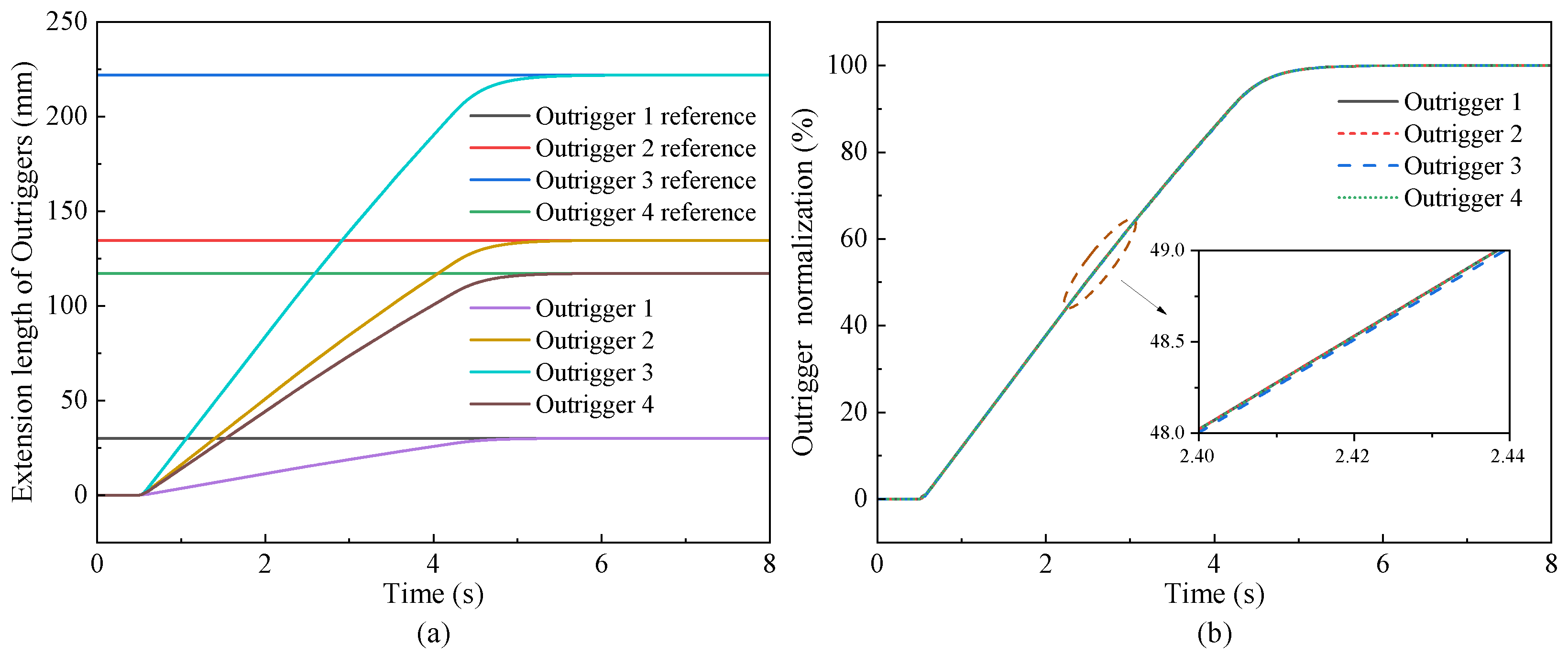
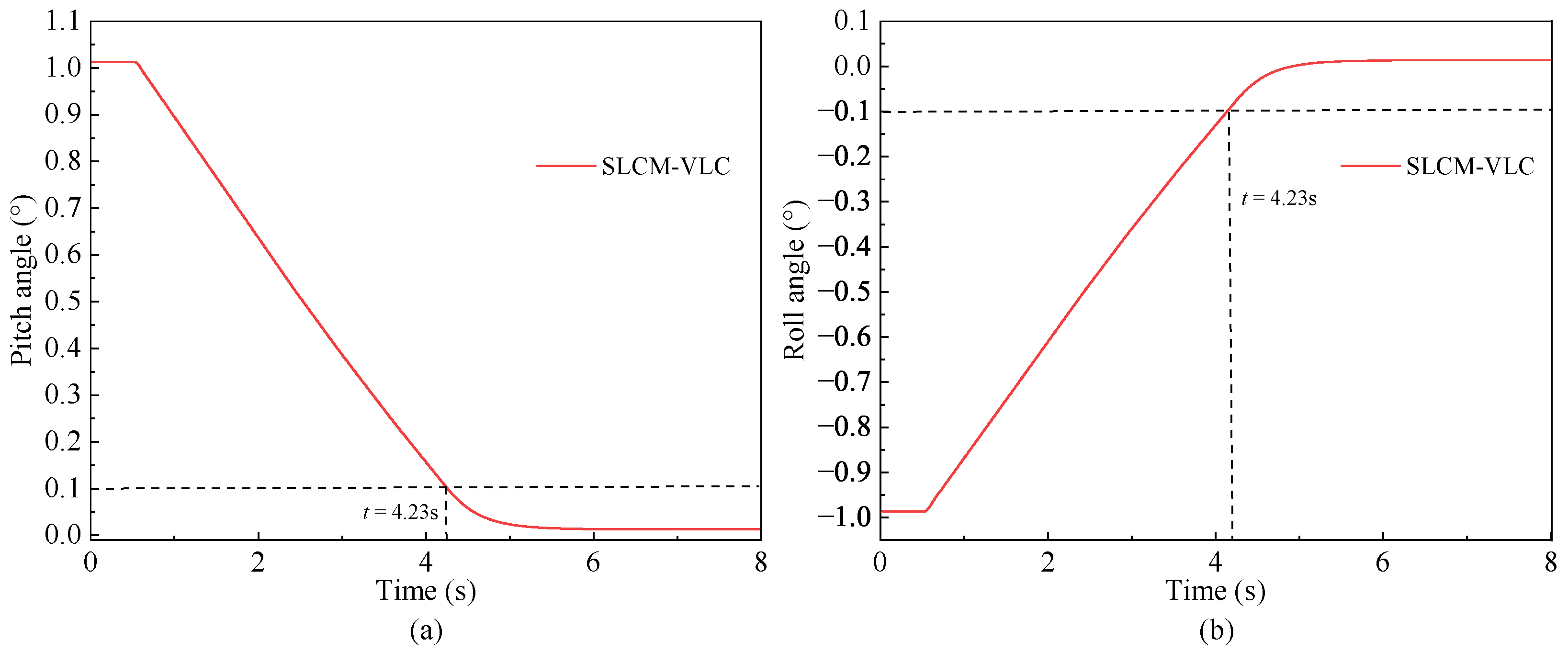
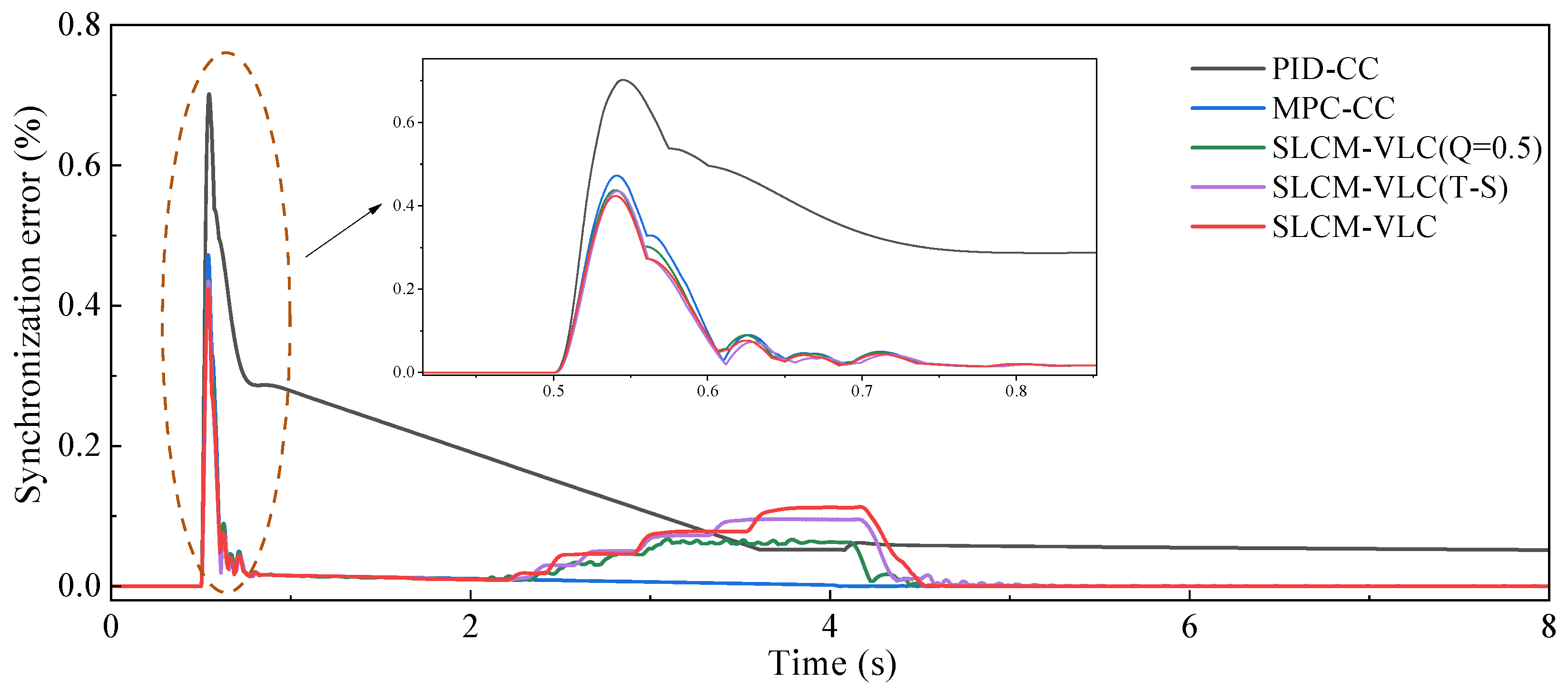
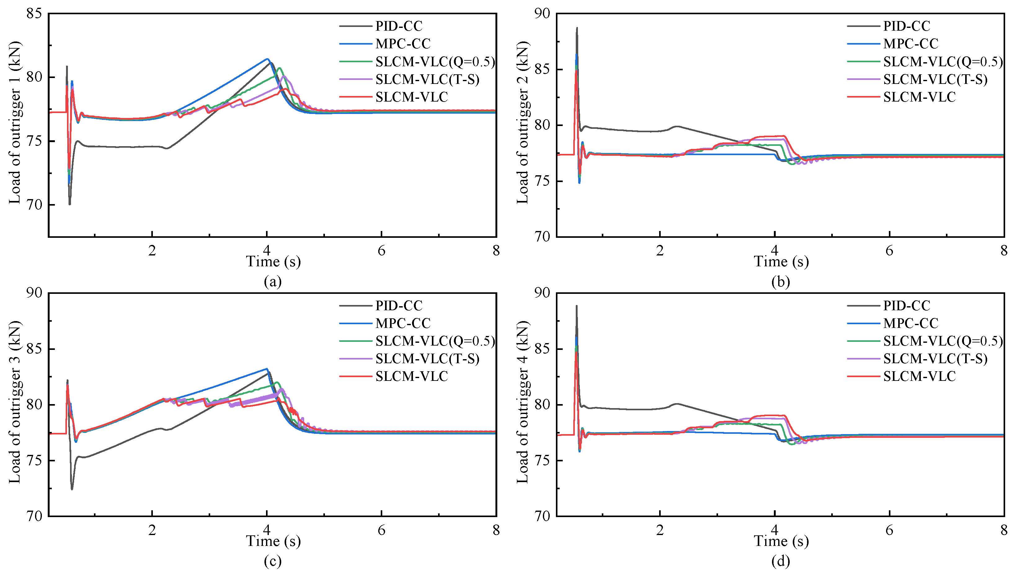
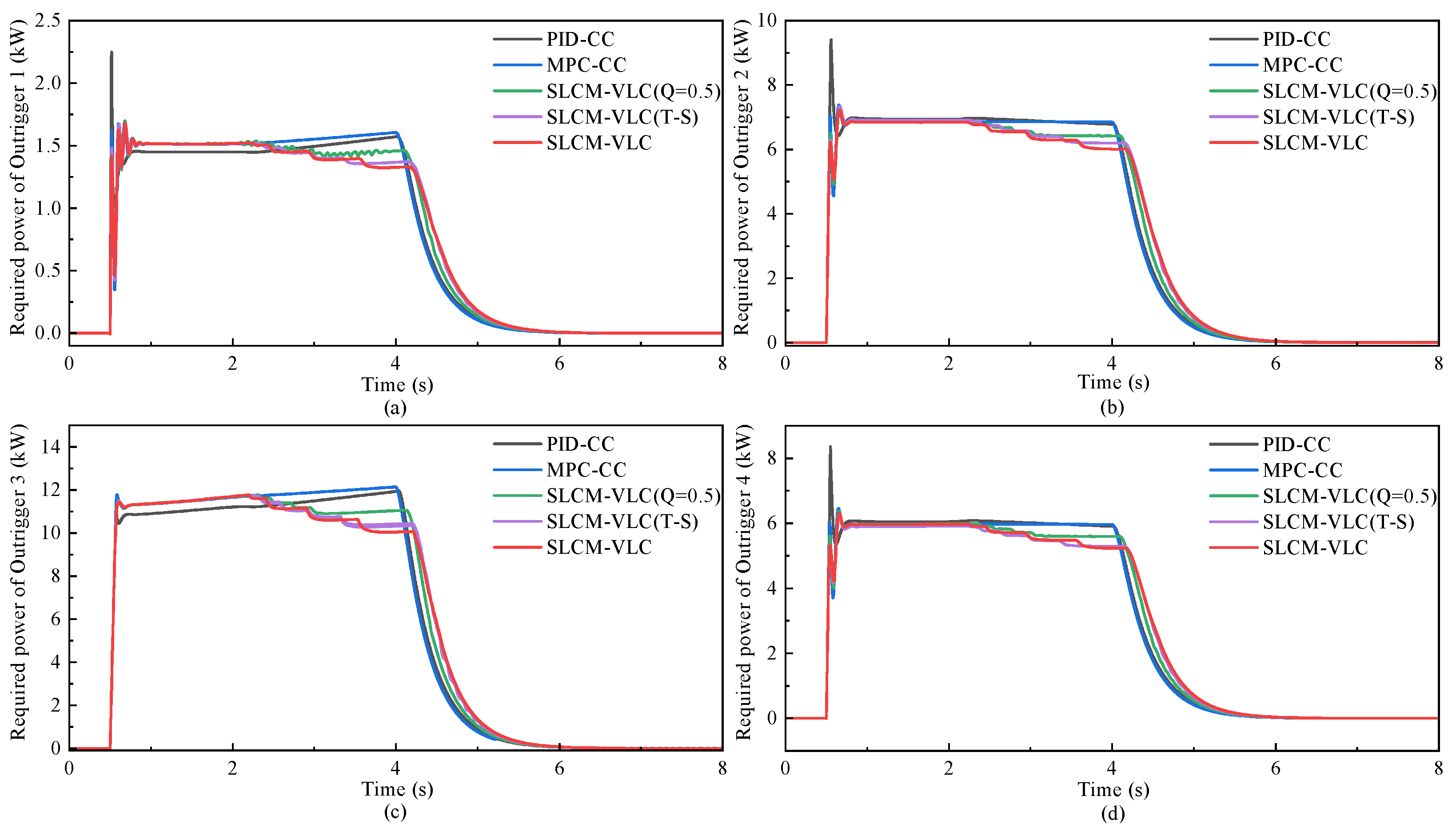
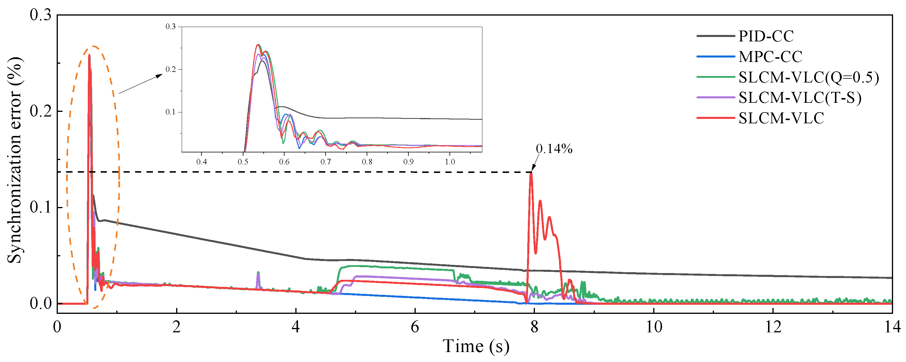
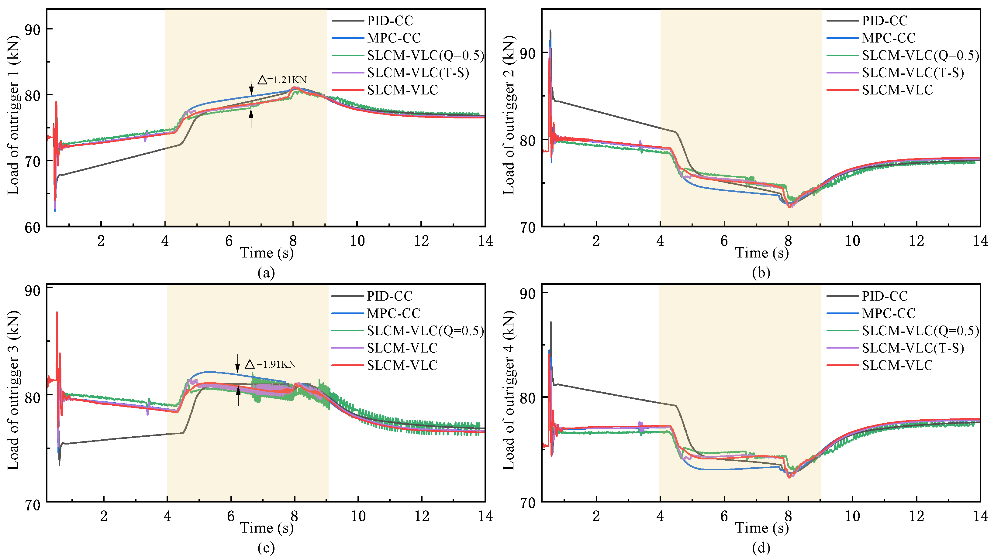
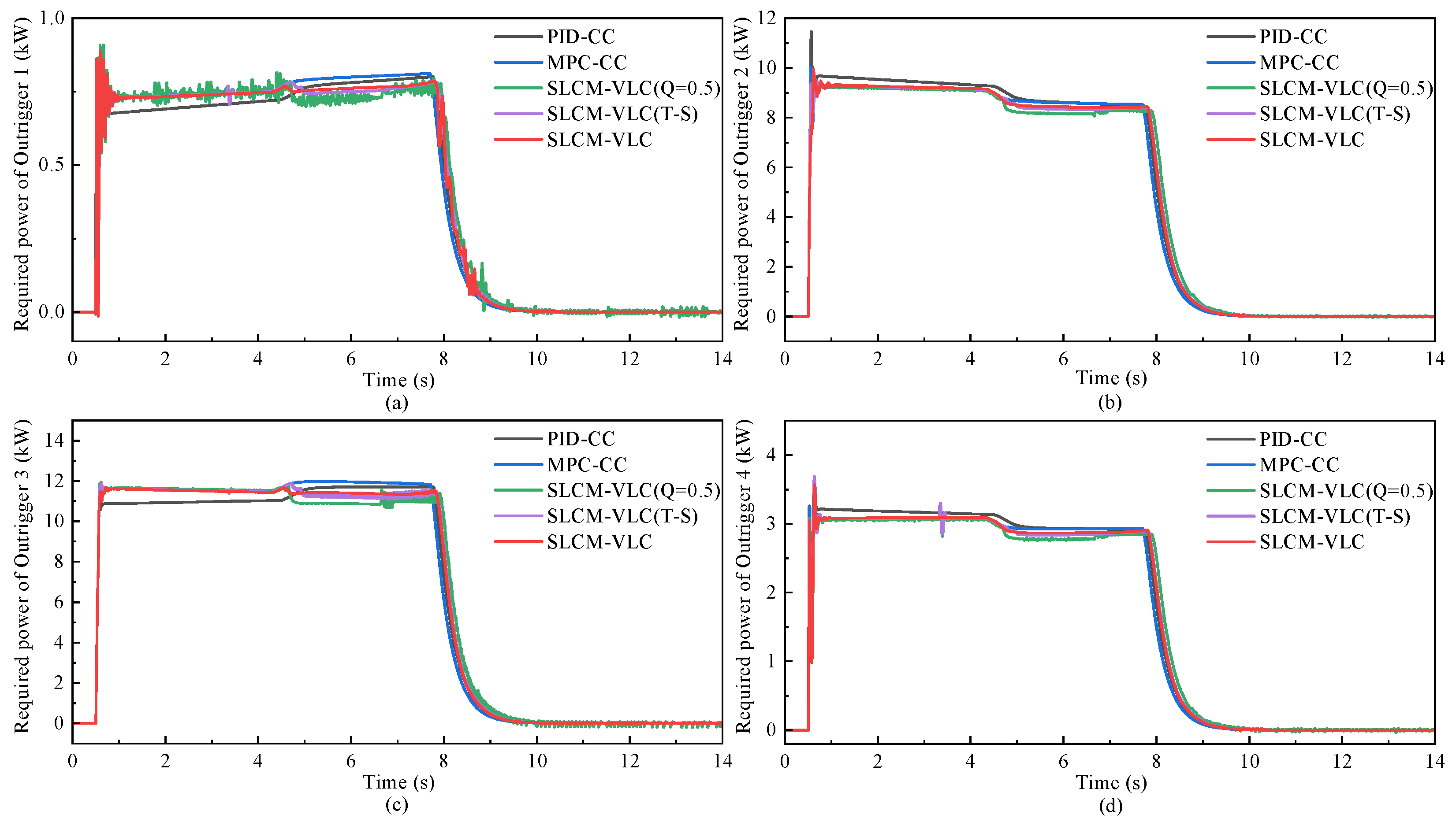
Aiming to achieve synchronous leveling of the crane outrigger platform with small peak load, a synchronous leveling control method with variable load constraints (SLCM-VLC) is proposed in this paper, which integrates the decision optimization of MPC, the nonlinear processing of fuzzy control, and the interference compensation of ESO. Based on the proposed strategy, a dynamic balance synchronization of the outrigger platforms is achieved with consideration of load constraints and compensation for model uncertainties and external disturbances. Meanwhile, for the purpose of validating the underlying logic and the reliability of the design approach, co-simulation and analysis verification based on Matlab, Soildworks, and Adams are carried out and have shown that the controller with the designed strategy is obviously better than the others. The simulation results proved the proposed SLCM-VLC can ensure high-precision leveling while reducing the maximum load and required power of the outriggers. For instance, the synchronous leveling of the vehicle is achieved with small synchronization error of the outriggers <1% and body angle ≤0.1° through the proposed SLCM-VLC on the flat road, improving the leveling precision compared with the other control strategies. At the same time, while reducing the load oscillation of the outriggers, the maximum load of the main bearing force outrigger is significantly reduced by 3.13% via introducing the variable weight load constraint strategy under rule regulation, which effectively improves the structural safety. Furthermore, the dynamic performance of the electric cylinder motor is optimized synchronously, whose overshoot is reduced by about 2% and the convergence speed is improved by the SLCM-VLC while reducing the required power.
The method’s efficacy has been validated by the above results, and it is important to acknowledge the limitations of the model and proposed method. For example, the model of the outrigger platform relied primarily on mathematical formulations that may not fully capture physical nonlinearities. Moreover, there is control error accumulation among the cascaded controllers of the SLCM-VLC, which affects the leveling accuracy and speed. In the future, our research will focus on exploring these limitations while considering factors such as structural elastic deformation and control delay on leveling control and completing the physical experiment, thereby achieving more extensive and effective technological advancements.
