Article

Neural Network Disturbance Observer-Based Adaptive Fault-Tolerant Attitude Tracking Control for UAVs with Actuator Faults, Input Saturation, and External Disturbances

1
School of Electronic and Electrical Engineering, Zhaoqing University, Zhaoqing 526061, China
2
School of Automation, Northwestern Polytechnical University, Xi’an 710129, China
*
Author to whom correspondence should be addressed.
Actuators 2025, 14(9), 437; https://doi.org/10.3390/act14090437
Submission received: 21 July 2025 / Revised: 27 August 2025 / Accepted: 2 September 2025 / Published: 3 September 2025
(This article belongs to the Section Control Systems)

Abstract

A dual-loop fault-tolerant control scheme is investigated for UAV attitude control systems subject to actuator faults, input saturation, and external disturbances in this paper. In the outer loop of attitude angles, a nonlinear dynamic inversion controller is developed as baseline controller for fast response and is augmented by a neural network disturbance observer to enhance the adaptability and robustness. Considering input saturation, actuator faults, and external disturbances in the inner loop of attitude angle velocities, the unbalanced input saturation is first converted into a time-varying system with unknown parameters and disturbances using a nonlinear function approximation method. An L1 adaptive fault-tolerant controller is then introduced to compensate for the effects of lumped uncertainties including system uncertainties, actuator faults, external disturbances, and approximation errors, and the stability and performance boundaries are verified by Lyapunov theorem and L1 reference system. Some simulation examples are carried out to demonstrate its effectiveness.

1. Introduction

In the past few decades, unmanned aerial vehicles (UAVs) have been widely used in various fields, and their reliability and safety have become particularly important. During flight, UAVs encounter various uncertainties, such as input saturation, actuator faults, and external disturbances. If these uncertainties are not addressed, they may lead to performance degradation or even instability. Fault-tolerant control (FTC) is employed to make control system fault-insensitive or self-recovering, capable of automatically eliminating undesired effects and accomplishing the control task with acceptable control performance. FTC based on fault detection and isolation (FDI) [1], FTC based on fault observers or estimators [2,3], and FTC that does not depend on fault values [4] are the most common FTC methods. Actuator faults and input saturation are two usual anomalous conditions of UAV actuators. Actuator faults are generally divided into loss of effectiveness (LOE), stuck, and float, and have been further categorized in some of the literature as multiplicative and additive faults. Input saturation is a prevalent nonlinear physical constraint that may affect the control outputs of actuators. When actuators are saturated for a long time, it may accelerate actuator damage and increase the chance of actuator faults. FTC schemes for actuator faults and input saturation have long been a focus of flight control system research, especially for fundamental and critical attitude control systems. For overcoming the attitude tracking performance degradation induced by input saturation and actuator faults, a large number of sophisticated control methods are applied, such as adaptive sliding mode control (SMC) [5,6], adaptive fuzzy control (FC) [7], backstepping control [8], etc. In addition, some integrated control strategies are applied to demonstrate their robust ability to actuator faults. A sliding mode observer-based neural network adaptive fault-tolerant controller is developed for the attitude control of a rigid spacecraft with external disturbances and actuator faults [9]. For actuator faults and saturation in a flying-wing aircraft, a dual-loop fault-tolerant attitude tracking controller combining nonlinear dynamic inversion (NDI), control allocation (CA), and optimal anti-windup compensator (AWC) is proposed in [10]. In addition to AWC, nonlinear function approximation is another popular method for dealing with input saturation, in which Gaussian error function [11] or hyperbolic tangent function [12,13] are commonly used approximation functions. This approach usually also requires the conversion of the saturation function into a time-varying system with unknown parameters and disturbances by the median theorem, and the effects of these uncertainties (unknown parameters, disturbances, and approximation errors) ultimately need to be taken into account in the design of the fault-tolerant controller. Designing auxiliary systems to compensate for input saturation is also an effective method. In [14], several auxiliary systems are designed to counteract the effects of actuator faults and input saturation, and system stability is analyzed using Lyapunov theory. Similarly, a series of auxiliary systems are introduced to prevent control input signals from exceeding boundaries, and the distributed finite-time fault-tolerant controller is designed to ensure stability and achieve control objectives in [15]. However, the fault-tolerant control algorithm by auxiliary systems is slightly complex, which may increase the difficulty of practical application.
UAVs are strongly coupled complex nonlinear systems that are vulnerable to various external disturbances in flight. Meanwhile, faults often occur along with external disturbances that exacerbate system uncertainties and cause greater damage. Numerous control policies are explored to cope with this unfavorable situation (e.g., FTC based on SMC [4], and FC [7]), among which FTC based on disturbance observer (DO) techniques is the most popular and effective approach. Sliding mode disturbance observer (SMDO) [16,17,18], adaptive disturbance observer (ADO) [19,20], and neural network disturbance observer (NNDO) [21,22] are widely used disturbance estimation algorithms. In addition, extended state observer (ESO) is also a utility auto-disturbance rejection control technique in [23,24,25]. Their main difference is that ESO estimates the extended state variables including external disturbances instead of estimating external disturbances directly. When UAVs may have both actuator faults and external disturbances, designing two observers to estimate faults and disturbances separately or a composite observer to estimate their lumped disturbances are both feasible approaches. To compensate for the negative effects of disturbances and actuator faults, a DO and a fault observer (FO) are designed separately in [26]. For hypersonic vehicles with external disturbances, actuator faults, and saturation, a composite sliding mode fault-tolerant controller is presented which combines some advanced control techniques such as AWC, ESO, and NNDO in [27]. The effectiveness of the control algorithm is verified by simulation results, but its structure is still somewhat complex. For a nonlinear Euler–Lagrange system in [28], a fixed-time ADO is designed by treating actuator faults and external disturbances as a lumped disturbance. Similarly, parametric uncertainty, actuator faults, and external disturbances in [29] are also viewed as a lumped disturbance, and a finite-time disturbance observer is explored for the disturbance estimation.
Considering the mobility and flexibility of UAVs, their FTC scheme should be simple in structure and easy to realize. Based on the analysis of the above research, this paper proposes a concise and easy-to-implement dual-loop fault-tolerant control scheme based on NNDO–NDI and L1 adaptive for the UAV attitude tracking control with external disturbances, actuator faults, and input saturation. An outer-loop NDI controller augmented by NNDO provides fast response and accurate attitude angle tracking. After the transformation of input saturation is accomplished by the nonlinear function approximation method, an L1 adaptive fault-tolerant controller of the inner loop consisting of the state predictor, adaptive laws, and the control law is designed to compensate for the lumped uncertainty. The stability and performance bounds are demonstrated through Lyapunov theorem and an introduced L1 reference system. L1 adaptive control is a modified model reference adaptive control (MRAC) proposed by Cao in 2006 [30]. It perfectly inherits the adaptive algorithm’s ability to handle system uncertainties and also effectively reduces the high-frequency oscillations induced by high gains in MRAC and enhances the system stability. The main contributions of this paper compared to previous research results are summarized below:
(1)
An NDI controller based on NNDO technique is proposed for the high precision attitude tracking of UAVs. It is clear from [1,10] that the typical NDI control law relies on the system model. The presence of uncertainties such as actuator faults, external disturbances, and input saturation can degrade the control performance. In this paper, introducing the estimation of NNDO in NDI control law can effectively enhance the disturbance immunity and robustness.
(2)
Unlike fault-tolerant control strategies based on fault detection or estimation in [1,4,5,6,8,22,23], the L1 adaptive fault-tolerant controller in this paper provides online estimation of a lumped uncertainty consisting of system uncertainties, actuator faults, external disturbances, and approximation errors, and designs a control law with a low-pass filter to counteract the negative effects. This proposed adaptive fault-tolerant controller has the advantage of simple algorithms and easy implementation because it does not require precise estimates of faults and disturbances.
(3)
Compared to the monotonous stability analysis of closed-loop systems in most of the existing research works, both the stability and performance bounds are rigorously derived in this paper by Lyapunov stability theorem and an L1 reference system, which provide strong guarantees for controller design and performance improvement.
The rest of this paper is organized as follows: The UAV’s attitude control system model and actuator fault model are described in Section 2. In Section 3, the design and performance analysis of a dual-loop fault-tolerant controller are presented. Simulation experiments are shown in Section 4. Finally, some conclusions are given in Section 5.

2. System Modeling

2.1. Attitude Control Systems for UAVs

To study the flight control system of a UAV, it is essential to establish its mathematical model. The conventional UAV is investigated in this paper, which is a time-varying, strongly coupled nonlinear system, and it is difficult to obtain the mathematical model accurately. Therefore, the following assumptions need to be introduced:
Assumption 1.
The UAV is rigid body of constant mass with symmetric geometry and internal mass distribution.
Assumption 2.
The terrestrial coordinate system is an inertial coordinate system and ignores the effects of earth’s curvature, rotation, etc.
Assumption 3.
Gravity acceleration does not vary with flight altitude.
The attitude kinematics and dynamics equations of UAVs are shown as follows [20]:
ϕ ˙ = p + ( r cos ϕ + q sin ϕ ) tan θ θ ˙ = q cos ϕ r sin ϕ ψ ˙ = 1 cos θ ( r cos ϕ + q sin ϕ )
p ˙ = c 1 q r + c 2 p q + c 3 L + c 4 N q ˙ = c 5 p r c 6 ( p 2 r 2 ) + c 7 M r ˙ = c 8 p q c 2 q r + c 4 L + c 9 N
The aerodynamic moments L , M and N in (2) are expressed as
L = Q S w b ( C l β β + C l δ a δ a + C l δ r δ r + C l p p ¯ + C l r r ¯ ) M = Q S w c A ( C m 0 + C m α α + C m δ e δ e ) N = Q S w b ( C n β β + C n δ a δ a + C n δ r δ r + C n p p ¯ + C n r r ¯ )
where p ¯ = p b 2 V , r ¯ = r b 2 V . The relevant parameters and their descriptions in (1) to (3) are summarized in Table 1 as follows:
Substituting the moments Equation (3) into (2) yields
p ˙ = ( c 1 r + c 2 p ) q + Q S w b ( c 3 C l p + c 4 C n p ) p ¯ + Q S w b ( c 3 C l r + c 4 C n r ) r ¯ + Q S w b ( c 3 C l β + c 4 C n β ) β + Q S w b ( c 3 C l δ a + c 4 C n δ a ) δ a + Q S w b ( c 3 C l δ r + c 4 C n δ r ) δ r q ˙ = c 5 p r c 6 ( p 2 r 2 ) + c 7 Q S w c A ( C m 0 + C m α α ) + c 7 Q S w c A C m δ e δ e r ˙ = ( c 8 p c 2 r ) q + Q S w b ( c 4 C l p + c 9 C n p ) p ¯ + Q S w b ( c 4 C l r + c 9 C n r ) r ¯ + Q S w b ( c 4 C l β + c 9 C n β ) β + Q S w b ( c 4 C l δ a + c 9 C n δ a ) δ a + Q S w b ( c 4 C l δ r + c 9 C n δ r ) δ r
Defining x 1 = [ ϕ , θ , ψ ] , x 2 = [ p , q , r ] and u 2 = [ δ a , δ e , δ r ] , attitude kinematics and dynamics Equations (1) and (4) can be written as the following affine nonlinear system:
x ˙ 1 = g 1 x 2 x ˙ 2 = g 2 u 2 + f y = C 1 x 1
where g 1 = 1 sin ϕ tan θ cos ϕ tan θ 0 cos ϕ sin ϕ 0 sin ϕ cos θ cos ϕ cos θ , g 2 = Q S w b c 3 C l δ a + c 4 C n δ a 0 c 3 C l δ r + c 4 C n δ r 0 c A b c 7 C m δ e 0 c 4 C l δ a + c 9 C n δ a 0 c 4 C l δ r + c 9 C n δ r ,
f = ( c 1 r + c 2 p ) q + Q S w b ( c 3 C l β β + c 3 C l p p ¯ + c 3 C l r r ¯ + c 4 C n β β + c 4 C n p p ¯ + c 4 C n r r ¯ ) c 5 p r c 6 ( p 2 r 2 ) + c 7 Q S w c A ( C m 0 + C m α α ) ( c 8 p c 2 r ) q + Q S w b ( c 4 C l β β + c 4 C l p p ¯ + c 4 C l r r ¯ + c 9 C n β β + c 9 C n p p ¯ + c 9 C n r r ¯ ) , C 1 = I 3 .
Remark 1.
From the above modeling process, it can be seen that the control algorithm developed in this paper is applicable to the affine nonlinear model as in (5), regardless of whether it is a fixed-wing UAV, a multi-rotor UAV or other control systems. Therefore, the control algorithm proposed in this paper has good scalability and adaptability. It is also assumed that all state variables (three attitude angles and their angular velocities) of the UAV attitude control system represented in (5) are measurable.

2.2. Actuator Fault

Consider the following actuator fault model:
u 2 = ω v 2 + v 2 a , t t f
where ω ( 0 , 1 ] is an actuator effectiveness factor, which may be constant or time-varying. v 2 is a virtual control input. v 2 a is a smooth function used to represent the unknown actuator additive faults. t f denotes the time when a fault occurs.
The actuator fault model expressed in (6) covers the following scenarios:
(1)
ω = 1 and v 2 a = 0 , no faults;
(2)
0 < ω < 1 and v 2 a = 0 , LOE (i.e., multiplicative fault);
(3)
ω = 1 and v 2 a 0 , additive fault;
(4)
0 < ω < 1 and v 2 a 0 , composite fault.
Remark 2.
From the above fault scenarios, it can be seen that the fault model expressed in (6) can represent most of the faults that may occur in UAVs, but it excludes severe faults (e.g., total LOE, stuck, and float) and unmodeled faults, which can be considered by means of CA, NN or fuzzy observers. Also, it does not take into account the unmodeled dynamics of actuators. On the other hand, multiplicative faults and additive faults often appear in many studies. The difference between them lies mainly in the different forms in which the faults act: multiplicative faults are manifested in the gain of the control signal (LOE is a multiplicative fault), while additive faults are expressed in the bias of the control signal. The fourth composite fault scenario indicates that both additive and multiplicative faults occur simultaneously.
By introducing the actuator fault model (6), input saturation, and external disturbances, the UAV attitude control system (5) can be rewritten as
x ˙ 1 = g 1 x 2 + d 1 x ˙ 2 = g 2 ω s a t ( v 2 ) + g 2 v 2 a + f + d 2 y = C 1 x 1
where s a t ( v 2 ) denotes the saturation nonlinearity of the control input v 2 . d 1 and d 2 are the disturbances induced by uncertainties such as system uncertainties, actuator faults, and external disturbances.
Assumption 4.
The disturbances  d 1  and  d 2  are bounded, i.e.,  d 1 Δ 1 , d 2 Δ 2 .
Assumption 5.
The nonlinear function  f  is bounded, i.e.,  f Δ 3 .
Remark 3.
The attitude control system for UAVs investigated in this paper is a nonlinear model with trimmed parameters to physically guarantee stable flight (such as moment of inertia, mass, wing-related parameters, and initial conditions, etc.). Meanwhile, this paper discusses bounded external disturbances and actuator faults, and extremely severe actuator faults such as total LOE, stuck, and float are not considered (as described in Assumption 4 and Remark 2). Therefore, under the physical parameters of trimmed UAVs and bounded uncertainties, some complicated unstable phenomena that may be induced by nonlinear dynamics could be ignored, such as chaotic motions, which is also the strategy adopted by most current fault-tolerant control schemes for UAVs.
The control objective of this paper is to design a fault-tolerant controller such that the UAV has good attitude tracking performance under actuator faults, input saturation, and external disturbances, and that all input and output signals remain asymptotically stable and bounded.

3. Design and Analysis of a Fault-Tolerant Controller for UAV Attitude Control System

According to the UAV attitude control system model (7), a dual-loop fault-tolerant control structure is proposed. An NDI baseline controller in the outer loop is designed for fast tracking of the attitude angles and is augmented with an NNDO to enhance the robustness. The inner-loop controller employs an L1 adaptive control algorithm to eliminate the negative effects of uncertainties such as actuator faults, input saturation, and external disturbances. The overall control structure is shown in Figure 1.

3.1. Design of the Outer-Loop Attitude Angle Controller

A baseline NDI controller is designed in the outer loop to realize the tracking of the attitude angles. NDI is a popular nonlinear control algorithm with fast response and simple structure, but its control effectiveness is often limited by the accuracy of the system model. Various system uncertainties may reduce modeling accuracy and degrade control performance. To enhance disturbance immunity and robustness of NDI controller, a DO based on the NN technique is investigated, and its stability is also demonstrated by the Lyapunov function.
For the outer-loop state equation in the system model (7), the following NDI controller is considered:
v 1 = g 1 1 ( D x ˜ 1 d 1 )
where x ˜ 1 = x 1 c x 1 denotes the tracking error of the attitude angles in the outer loop, and x 1 c is the given attitude angle signal. D represents the outer-loop bandwidth matrix, which is generally at least three times smaller than the inner-loop bandwidth according to the time scale separation principle. As can be seen in Figure 1, the output signal v 1 of the NDI controller is also the reference signal of the inner loop.
It is obvious that this control law (8) cannot be realized directly because of the unknown function d 1 . After estimating the disturbance d 1 by means of the good approximation ability of radial basis function neural network (RBFNN) to nonlinear functions, the NDI control law expressed in (8) is rewritten as
v 1 = g 1 1 ( D x ˜ 1 d ^ 1 ) d ^ 1 = W ^ T Φ ( x 1 )
where W ^ = [ W ^ 1 , , W ^ n ] denotes weight matrix for the output layer of RBFNN, and n is the number of output nodes. Φ ( x 1 ) = [ Φ 1 ( x 1 ) , , Φ m ( x 1 ) ] represents the basis function, which is expressed as follows:
Φ i ( x 1 ) = exp x 1 l i 2 2 k i 2 , i = 1 , , m
where k i and l i are the width and center of the i t h hidden layer node. m is the number of hidden layer nodes.
Let d ˜ 1 = d ^ 1 d 1 , and the optimal weight W o p t in a compact region Ω is defined as
W o p t = arg min W Ω sup t 0 d ˜ 1
In further, the weight error W ˜ can be defined as
W ˜ = W o p t W ^
Combined with the definition of W o p t in (11), the unknown function d 1 can be written as
d 1 = W o p t T Φ ( x 1 ) + ε
where ε is a uniformly bounded approximation error on the compact set S 1 , and ε ε ¯ .
For the outer loop in the system model (7), the following auxiliary dynamic system is considered:
ζ ˙ = σ ζ + p ( x 1 , x 2 ) p ( x 1 , x 2 ) = σ x 1 + g 1 x 2 + d ^ 1
where ζ and p ( x 1 , x 2 ) are the state variable and auxiliary variable of the dynamic system. σ = d i a g ( σ 1 , σ 2 , σ 3 ) is a positive matrix to be designed.
Define the nominal error of the disturbance observer as
e = x 1 ζ
The following Theorem 1 verifies the uniformly boundedness of the nominal error e and the estimation error d ˜ 1 .
Theorem 1.
For the disturbance observer (9) and the auxiliary dynamic system (14), if the adaptive law for  W ^  is chosen to be
W ^ ˙ = γ e Φ ( x 1 )
where  γ > 0  is an adaptive gain, then both  e  and  d ˜ 1  are uniformly bounded.
Proof of Theorem 1.
From (9), (12)–(15), the derivative of e can be derived as
e ˙ = x ˙ 1 ζ ˙ = g 1 x 2 + d 1 ( σ ζ + σ x 1 + g 1 x 2 + d ^ 1 ) = σ ( ζ x 1 ) + d 1 d ^ 1 = σ e + d 1 d ^ 1 = σ e + W o p t T Φ ( x 1 ) + ε W ^ T Φ ( x 1 ) = σ e + W ˜ T Φ ( x 1 ) + ε
The following Lyapunov function is chosen:
V = 1 2 e T e + 1 2 γ i = 1 n W ˜ i T W ˜ i
Combined with the adaptive law of W ^ in (16), the derivative of V is given by
V ˙ = e T e ˙ + 1 γ i = 1 n W ˜ i T W ˜ ˙ i = e T e ˙ 1 γ i = 1 n W ˜ i T W ^ ˙ i = i = 1 n e i ( σ i e i + W ˜ i T Φ ( x 1 ) + ε i ) 1 γ i = 1 n W ˜ i T W ^ ˙ i = i = 1 n e i ( σ i e i + W ˜ i T Φ ( x 1 ) + ε i ) 1 γ i = 1 n W ˜ i T γ e i Φ ( x 1 ) = i = 1 n e i ( σ i e i + ε i ) = i = 1 n σ i 2 e i 2 + 1 2 σ i ε i 2 σ i 2 e i 1 2 σ i ε i 2 i = 1 n σ i 2 e i 2 + 1 2 σ i ε i 2
Combining (19) and the upper boundary of the approximation error ε in (13) yields that V ˙ < 0 when e i > ε ¯ σ i , which indicates that the error e is uniformly bounded. It follows from (17) that when e is uniformly bounded, the estimation error d ˜ 1 is also uniformly bounded. □
Remark 4.
It is noted that the above NNDO has the advantages of simple algorithm and easy operation, but its convergence time is not considered in the design of NNDO, which is a pity for the UAV tracking problem that requires fast convergence. For the finite-time convergence problem, the improvement of NNDO by combining finite-time techniques and reinforcement learning can be developed in future work to enhance the fast convergence and robustness [31,32,33].

3.2. Design and Analysis of the Inner-Loop Attitude Angular Velocity Controller

The attitude control system model in (7) shows that the attitude angular velocity loop is affected by external disturbances, actuator faults, and saturation. To handle these system uncertainties, an L1 adaptive fault-tolerant controller is designed in this section. L1 adaptive algorithm is derived from MRAC, which decouples fast adaptation and robustness by introducing a low-pass filter in the control law. The nonlinear characteristic of control input saturation is detrimental to the controller design, so a hyperbolic tangent function is considered next for the approximation of the saturation function s a t ( v 2 ) in (7).

3.2.1. Conversion of the Input Saturation Function

The input saturation constraint s a t ( v 2 ) in the attitude control system model (7) is represented by the following nonlinear saturation function:
s a t ( v 2 ) = u 2 = u 2 max , v 2 u 2 max v 2 , u 2 min < v 2 < u 2 max u 2 min , v 2 u 2 min
where u 2 max and u 2 min indicate the upper and lower boundaries of the control input u 2 .
Consider the following hyperbolic tangent function to approximate the saturation function (20):
h ( v 2 ) = u 2 max e v 2 u 2 max e v 2 u 2 max e v 2 u 2 max + e v 2 u 2 max , v 2 0 u 2 min e v 2 u 2 min e v 2 u 2 min e v 2 u 2 min + e v 2 u 2 min , v 2 < 0
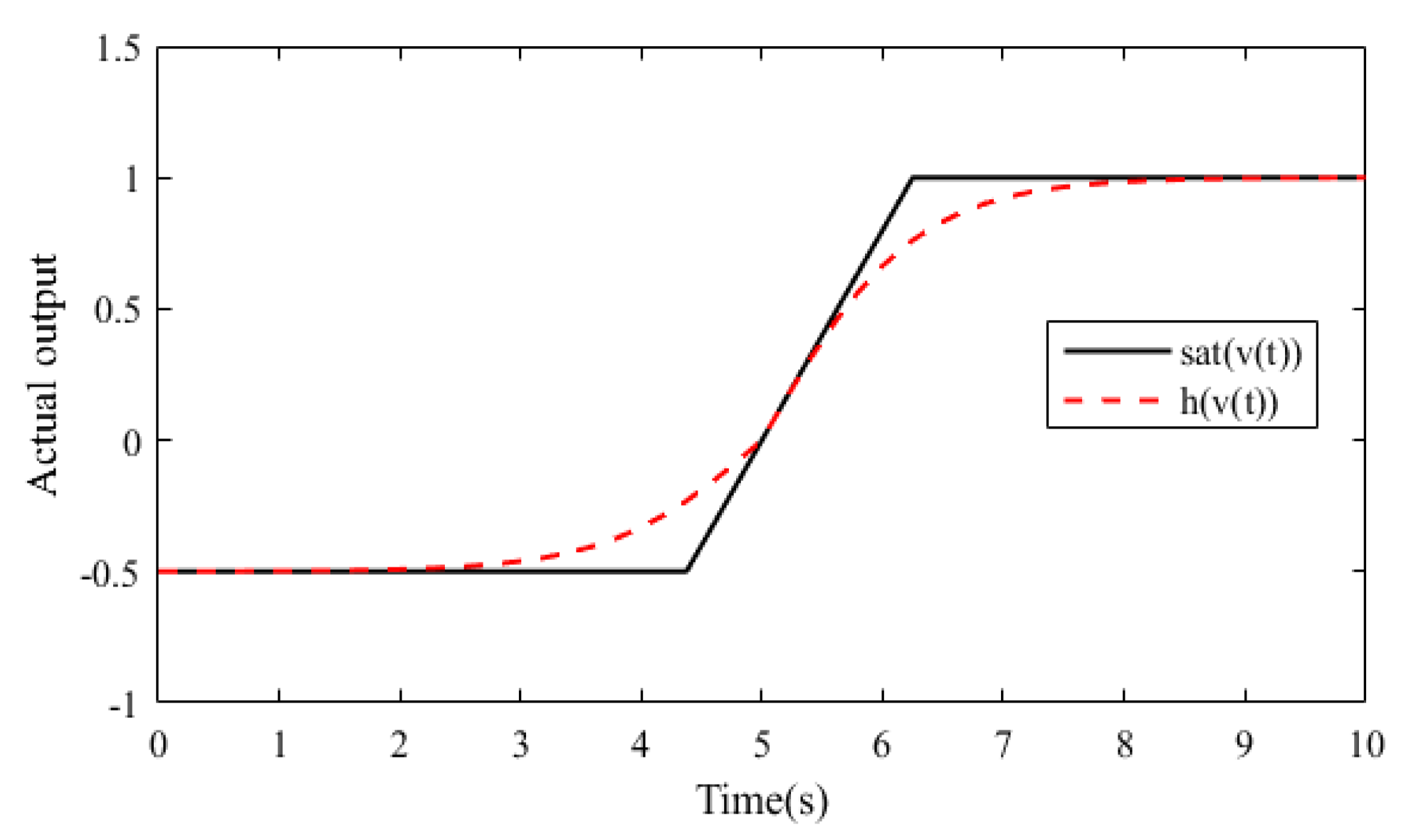
Figure 2 shows the response curves for s a t ( v 2 ) and h ( v 2 ) when u 2 max = 1 and u 2 min = 0.5 , which illustrates that the hyperbolic tangent function has good approximation to the saturation function.
According to the Lagrange median theorem, there exists v 2 * ( 0 , v 2 ) such that the following equation holds:
h ( v 2 ) = h ( 0 ) + h v 2 | v 2 = v 2 * v 2
It is obvious from the definition of h ( v 2 ) in (21) that h ( 0 ) = 0 . Define h * = h v 2 | v 2 = v 2 * , and the hyperbolic tangent function (22) can be rewritten as
h ( v 2 ) = h * v 2
Considering the approximation error e h , the saturation function s a t ( v 2 ) can be rewritten as
s a t ( v 2 ) = u 2 = h * v 2 + e h
It can be seen from (24) that the nonlinear saturation constraint s a t ( v 2 ) is transformed into a time-varying system with an unknown parameter h * and a time-varying disturbance e h , with e h { u max ( 1 tanh ( 1 ) ) , u min ( tanh ( 1 ) 1 ) } = e ¯ h .
By substituting (24) into (7), the following mathematical model of the inner loop of the UAV attitude control system is obtained:
x ˙ 2 = g 2 ω ( h * v 2 + e h ) + g 2 v 2 a + f + d 2 = g 2 ω h v 2 + g 2 ω e h + g 2 v 2 a + f + d 2 = g 2 ω h v 2 + f ¯
where f ¯ = g 2 ω e h + g 2 v 2 a + f + d 2 represents the bounded uncertainties involving system uncertainty, input saturation, faults, and external disturbances. ω h = ω h * .

3.2.2. Design of the L1 Adaptive Fault-Tolerant Controller

To counteract the effect of uncertainties in system model (25), an L1 adaptive controller is designed. The control law v 2 consists of two parts: a linear control law v 2 l and an adaptive control law v 2 a d . The linear control law can be considered as v 2 l = K 0 T x 2 , which aims to ensure the stability and desired dynamic characteristics of the closed-loop system by utilizing state feedback methods. In order to design the adaptive control law more conveniently, the system model (25) is first converted to a nonlinear system with unknown parameters and disturbances based on the Erzberger model full tracking condition [34]. Define the system matrix A m of the reference model as A m = A l B m K 0 T , where A l and B m are the linear parts of the system matrix and the input matrix, both of which can be derived from the nonlinear model in (25). By substituting the L1 adaptive control law v 2 described above, the nonlinear model of (25) can be further derived as
x ˙ 2 = g 2 ω h v 2 + f ¯ = A l x 2 + B m ω h ( K 0 T x 2 + v 2 a d ) + f ¯ A l x 2 = ( A l B m K 0 T ) x 2 + B m ω h v 2 a d + B m ( 1 ω h ) K 0 T x 2 + f ¯ A l x 2 = A m x 2 + B m ω h v 2 a d + f m i x
where f m i x = B m ( 1 ω h ) K 0 T x 2 + f ¯ A l x 2 is a lumped disturbance that includes input saturation, faults, external disturbances, and system uncertainties.
Next, another RBFNN is designed to approximate the lumped disturbance f m i x . The system model of (26) can be rewritten as
x ˙ 2 = A m x 2 + B m ( ω h v 2 a d + W f T Φ f ( x 2 ) + ε f )
where W f and Φ f ( x 2 ) are weight matrix and the basis function, respectively. The basis function Φ f ( x 2 ) adopts the same form as NNDO in (10). ε f Δ 4 is a uniformly bounded approximation error on the compact set S 2 .
Assumption 6.
The nonlinear function  f m i x  is bounded, i.e.,
f m i x Δ 5
Assumption 7.
Let  Δ f x ( δ ) > 0  and  Δ f t ( δ ) > 0 , δ > 0 then the partial differentials of  f m i x  are semiglobal uniformly bounded, i.e.,
f m i x x 2 Δ f x ( δ ) f m i x t Δ f t ( δ )
For the system model (27), the following state predictor is designed:
x ^ ˙ 2 = A m x ^ 2 + B m ( ω ^ h v 2 a d + W ^ f T Φ f ( x 2 ) + ε ^ f ) + K 1 x ˜ 2
where ω ^ h , W ^ f and ε ^ f denote estimates of the unknown parameters ω h , W f and ε f . K 1 is a constant matrix defined via A s = A m + K 1 and such that A s is Hurwitz. x ˜ 2 = x ^ 2 x 2 denotes the estimation error of the state variable x 2 .
The adaptive laws for unknown parameters are given as
ω ^ ˙ h = Γ p r o j ( ω ^ h , x ˜ 2 T P B m v 2 a d ) W ^ ˙ f = Γ p r o j ( W ^ f , x ˜ 2 T P B m Φ f ( x 2 ) ) ε ^ ˙ f = Γ p r o j ( ε ^ f , x ˜ 2 T P B m )
where Γ > 0 is an adaptive gain to be selected. P = P T > 0 is the solution of the Lyapunov algebraic equation A s T P + P A s = Q , Q = Q T > 0 . p r o j ( , ) is a projection operator that guarantees boundedness of the adaptive parameters [35].
The following control law with a low-pass filter is given:
v 2 a d ( s ) = K 3 D ( s ) ( η ^ ( s ) K 2 r ( s ) )
where η ^ ( s ) is the Laplace transform of η ^ ( t ) = ω ^ h v 2 a d ( t ) + W ^ f T Φ f ( x 2 ) + ε ^ f . r ( s ) represents the Laplace transform of the reference signal r ( t ) , which is also the output signal of the outer loop. K 2 can be designed as K 2 = ( C 1 A s 1 B m ) 1 based on the MRAC theory such that the reference signal r ( s ) is tracked by the output signal y ( s ) in steady state.
In the control law of (32), K 3 and D ( s ) are two important parameters of the low-pass filter C ( s ) , which is defined as C ( s ) = ω h K 3 D ( s ) I + ω h K 3 D ( s ) with C ( 0 ) = 1 . Obviously, the introduction of the low-pass filter C ( s ) limits the effective bandwidth and permits the control law to compensate only for the uncertainties within the control channel. What is more, the low-pass filter may cause system instability. To guarantee the stability of the closed-loop system, the choice of C ( s ) needs to satisfy the following L1-norm condition. For a given σ 0 > 0 , if σ r > σ i n , σ i n = s ( s I A s ) 1 L 1 σ 0 , L δ = δ ¯ ( δ ) δ Δ f x ( δ ¯ ( δ ) ) , δ ¯ ( δ ) = δ + γ ¯ 1 , in which γ ¯ 1 is an arbitrary positive constant, Δ f x and δ are defined in Assumption 7. The L1-norm condition can be validated as follows:
G ( s ) L 1 < σ r H ( s ) C ( s ) K 2 L 1 r τ L σ i n L σ r σ r + Δ 5
where
G ( s ) = H ( s ) ( I C ( s ) )
H ( s ) = ( s I A s ) 1 B m
From the above discussion, the L1 adaptive fault-tolerant controller is constructed via (30)–(32) while satisfying the L1-norm condition of (33). The next section analyzes the performance of the proposed L1 adaptive controller in terms of system stability and performance boundaries.

3.2.3. Performance Analysis of the L1 Adaptive Fault-Tolerant Controller

  • Stability analysis
By subtracting (27) from (30), the state estimation error dynamics is given:
x ˜ ˙ 2 = A s x ˜ 2 + B m ( ω ˜ h v 2 a d + W ˜ f T Φ f ( x 2 ) + ε ˜ f ) , x ˜ 2 ( 0 ) = 0
where ω ˜ h = ω ^ h ω h , W ˜ f = W ^ f W f , and ε ˜ f = ε ^ f ε f denote the estimation errors of the unknown parameters ω h , W f , and ε f , respectively.
To illustrate the boundedness of the state estimation error x ˜ 2 , the following Lemma 1 needs to be introduced:
Lemma 1 (Barbalat’s lemma [36]).
For a uniformly continuous function  l ( t )  on  [ 0 , ) , if  lim t 0 t l ( τ ) d τ  exists and is finite, then
lim t l ( t ) = 0
Theorem 2.
For the closed-loop system (27), if  x 2  and  v 2 a d  are bounded, then  x ˜ 2  is also bounded, that is,  x ˜ 2 τ L  is upper-bounded.
Proof of Theorem 2.
Define the optimal approximation weight of f m i x as
W ^ o p t f = arg min W f Ω f sup t 0 f ^ m i x f m i x
From (38), the minimum estimation error can be defined as
e min = f ^ m i x | W ^ o p t f f m i x
The state estimation error Equation (36) is rewritten as
x ˜ ˙ 2 = A s x ˜ 2 + B m e min + B m ( ω ˜ h v 2 a d + φ T Φ f ( x 2 ) + ε ˜ f )
where φ = W ^ f W ^ o p t f .
The following Lyapunov function is chosen:
V = 1 2 x ˜ 2 T P x ˜ 2 + 1 2 Γ t r ( ω ˜ T h ω ˜ h ) + 1 2 Γ φ T φ + 1 2 Γ ε ˜ f T ε ˜ f
V ˙ is derived as follows:
V ˙ = 1 2 ( x ˜ ˙ 2 T P x ˜ 2 + x ˜ 2 T P x ˜ ˙ 2 ) + 1 Γ t r ( ω ˜ h T ω ˜ ˙ h ) + φ T φ ˙ + ε ˜ f T ε ˜ ˙ f
Combining Equations (40) and (31) gives
V ˙ 1 2 x ˜ 2 T Q x ˜ 2 + x ˜ 2 T P B m e min 1 2 λ Q min x ˜ 2 2 + x ˜ 2 T P B m e min = ( λ Q min 1 ) 2 x ˜ 2 2 1 2 ( x ˜ 2 2 2 x ˜ 2 T P B m e min + P B m e min 2 ) + 1 2 P B m e min 2 ( λ Q min 1 ) 2 x ˜ 2 2 + 1 2 P B m e min 2
where Q is introduced in (31), and λ Q min is its minimum eigenvalue.
To further simplify (43), λ Q min > 1 is assumed, which is easily satisfied during the selection of the parameter P in (31). Accordingly, (43) can be rewritten as
0 t x ˜ 2 2 d τ 2 λ Q min 1 ( V ( 0 ) + V ( t ) ) + 1 λ Q min 1 P B m 2 0 t e min 2 d τ
This follows from Lemma 1 and the definition of the Lyapunov function in (41), lim t x ˜ 2 2 = 0 , which implies that the state estimation error x ˜ 2 is bounded. For the convenience of the later presentation, define x ˜ 2 τ L γ 0 , where γ 0 > 0 is an arbitrarily small constant. □
2.
Performance boundaries analysis
To analyze the L1 adaptive controller performance, the following L1 reference system is introduced:
x ˙ r e f = A s x r e f + B m ( ω h v r e f + W f T Φ f ( x r e f ) + ε f ) v r e f ( s ) = C ( s ) ω h 1 ( K 2 r ( s ) η 1 ( s ) ) y r e f = C 1 x r e f , x r e f ( 0 ) = x 20
where x r e f , y r e f , and v r e f denote the state variable, output signal, and control input signal of the L1 reference system. η 1 ( s ) is the Laplace transform of η 1 = W f T Φ f ( x r e f ) + ε f . Let η 2 = W f T Φ f ( x 2 ) + ε f , and η 1 , η 2 satisfy the following semiglobal Lipschitz condition.
Assumption 8 (semiglobal Lipschitz condition on  η 1  and  η 2 ).
For an arbitrary  δ > 0 , there exists L δ > 0  such that  η 1 ( x r e f , t ) η 2 ( x 2 , t ) L L δ x r e f x 2 L , for all  x r e f L δ  and  x 2 L δ  uniformly in  t .
The state equation of the L1 reference system (45) can be rewritten in the frequency domain as
x r e f ( s ) = G ( s ) η 1 ( s ) + H ( s ) C ( s ) K 2 r ( s ) + x r e f 0
where G ( s ) and H ( s ) are defined in (34) and (35), and x r e f 0 = ( s I A s ) 1 x r e f ( 0 ) . Recalling the definition of σ i n in (33) and A s is Hurwitz, there exists x r e f 0 L σ i n .
Lemma 2 [37].
For a stable proper MIMO system  H ( s )  with input signal  r ( t )  and output signal  y ( t ) , y t L H L 1 r t L  holds  t > 0 .
The stability of the L1 reference system (45) is verified by the following Lemma 3.
Lemma 3.
For the given L1 reference system (45), subject to the L1-norm condition (33), if  x 20 σ 0 , then
x r e f L < σ r
v r e f L < σ u r
where  σ 0  and  σ r  are positive constants introduced in the L1-norm condition (33), and   σ u r = C ( s ) ω h 1 L 1 ( K 2 r τ L + L σ r σ r + Δ 5 ) .
Proof of Lemma 3.
Combined with Lemma 2, (46) can be rewritten as
x r e f τ L G ( s ) L 1 η 1 τ L + H ( s ) C ( s ) K 2 L 1 r τ L + x r e f 0 L
Assuming that (47) does not hold, since x r e f ( 0 ) = x 20 σ 0 < σ r and x r e f ( t ) is a continuous function, there exists τ > 0 such that
x r e f ( t ) < σ r , t [ 0 , τ ) x r e f ( τ ) = σ r
which implies that the following relationship holds:
x r e f τ L = σ r
Based on Assumption 8, an upper bound of η 1 τ can be obtained as follows:
η 1 τ L L σ r σ r + Δ 5
Consider the upper bound of x r e f 0 in (46), substituting (52) into (49) yields
x r e f τ L G ( s ) L 1 ( L σ r σ r + Δ 5 ) + H ( s ) C ( s ) K 2 L 1 r τ L + σ i n
Meanwhile, the L1-norm condition in (33) is rewritten as
G ( s ) L 1 ( L σ r σ r + Δ 5 ) < σ r H ( s ) C ( s ) K 2 L 1 r τ L σ i n
By substituting (54) into (53), it can be derived
x r e f τ L < σ r
It is clear that the conclusion (55) contradicts (51), which also implies that (47) holds.
Combining (52) and Lemma 2, the definition of v r e f in (45) can be rewritten as
v r e f L < C ( s ) ω h 1 L 1 ( K 2 r τ L + L σ r σ r + Δ 5 )
which proves that (48) holds. □
The following Theorem 3 illustrates the performance bounds of the closed-loop system (27).
Theorem 3.
Consider the closed-loop system (27) with the L1 adaptive controller consisting of (30)–(32), subject to the L1-norm condition in (33), and the reference system (45), if  x 20 σ 0 , then
x r e f x 2 L γ 1
v r e f v 2 a d L γ 2
y r e f y L C 1 L 1 γ 1
where  σ 0  and  γ 0  are introduced in (33) and Theorem 2. γ 1  and  γ 2  are defined as
γ 1 = C ( s ) L 1 1 G ( s ) L 1 L σ r γ 0
γ 2 = H 1 ( s ) ω h 1 L 1 γ 0 + C ( s ) ω h 1 L 1 L σ r γ 1
Proof of Theorem 3.
The closed-loop system model (27) can be rewritten in the frequency domain as
x 2 ( s ) = H ( s ) ( ω h v 2 a d ( s ) + η 2 ( s ) ) + x r e f 0
where η 2 ( s ) is the Laplace transform of η 2 = W f T Φ f ( x 2 ) + ε f .
The control law of (32) can also be rewritten as
v 2 a d ( s ) = K 3 D ( s ) ( ω h v 2 a d ( s ) + η 2 ( s ) + η ˜ ( s ) K 2 r ( s ) )
where η ˜ ( s ) is the Laplace transform of ω ˜ h v 2 a d ( s ) + W ˜ f T Φ f ( x 2 ) + ε ˜ f .
From (63), it is obtained
v 2 a d ( s ) = K 3 D ( s ) I + K 3 ω h D ( s ) ( η 2 ( s ) + η ˜ ( s ) K 2 r ( s ) )
Recalling the definition of the low-pass filter C ( s ) in (33), (64) is further simplified as
v 2 a d ( s ) = C ( s ) ω h 1 ( η 2 ( s ) + η ˜ ( s ) K 2 r ( s ) )
Substituting (65) into (62) yields
x 2 ( s ) = H ( s ) ( 1 C ( s ) ) η 2 ( s ) H ( s ) C ( s ) ( η ˜ ( s ) K 2 r ( s ) ) + x r e f 0 = G ( s ) η 2 ( s ) H ( s ) C ( s ) ( η ˜ ( s ) K 2 r ( s ) ) + x r e f 0
Subtracting (66) from (46) gives
x r e f ( s ) x 2 ( s ) = G ( s ) ( η 1 ( s ) η 2 ( s ) ) + H ( s ) C ( s ) η ˜ ( s )
From the state estimation error Equation (36) and the definition of η ˜ ( s ) in (63), it follows that
x ˜ 2 ( s ) = H ( s ) η ˜ ( s )
Substituting (68) into (67), one leads to
x r e f ( s ) x 2 ( s ) = G ( s ) ( η 1 ( s ) η 2 ( s ) ) + C ( s ) x ˜ 2 ( s )
Combined with Lemma 2, (69) can be rewritten as
( x r e f x 2 ) τ L G ( s ) L 1 ( η 1 η 2 ) τ L + C ( s ) L 1 x ˜ 2 τ L
Consider Assumption 8 and the definition of L σ r in (33), which gives
( η 1 η 2 ) τ L L σ r ( x r e f x 2 ) τ L
Recalling the definition of γ 0 in Theorem 2, substituting (71) into (70) yields
( x r e f x 2 ) τ L G ( s ) L 1 L σ r ( x r e f x 2 ) τ L + C ( s ) L 1 γ 0
Further simplification of (72) leads to
x r e f x 2 L C ( s ) L 1 1 G ( s ) L 1 L σ r γ 0
which proves that (57) holds.
Combining (65) and the reference control law in (45), one is derived
v r e f ( s ) v 2 a d ( s ) = C ( s ) ω h 1 η ˜ ( s ) C ( s ) ω h 1 ( η 1 ( s ) η 2 ( s ) )
Substituting (68) into (74), it is obtained
v r e f ( s ) v 2 a d ( s ) = H 1 ( s ) ω h 1 x ˜ 2 ( s ) C ( s ) ω h 1 ( η 1 ( s ) η 2 ( s ) )
where H 1 ( s ) = C ( s ) 1 c 0 T H ( s ) c 0 T , and c 0 R guarantees that H 1 ( s ) is a suitable and stable system.
Considering Lemma 2 and (71), (75) can be rewritten as
v r e f v 2 a d τ L H 1 ( s ) ω h 1 L 1 x ˜ 2 ( s ) L + C ( s ) ω h 1 L 1 L σ r ( x r e f x 2 ) τ L
Combining the definition of γ 0 in Theorem 2 and (57), one can be obtained
v r e f v 2 a d τ L H 1 ( s ) ω h 1 L 1 γ 0 + C ( s ) ω h 1 L 1 L σ r γ 1
which proves that (58) holds.
From the output equations in (7) and (45), it is derived
y r e f y = C 1 x r e f x 1
Based on Lemma 2 and (57), (59) can be obviously proved. □

4. Simulation Experiments

In this section, simulation experiments are carried out on a 6-DOF fixed-wing UAV to illustrate the effectiveness of the proposed controller. The main parameters of the nonlinear model of the trimmed UAV used for simulation experiments are chosen as follows: m = 425 kg ,   S w = 80 m 2 ,   b = 50 m ,   c A = 1.634 m ,   J = [ 52723 , 0 , 8435 ; 0 , 6314 , 0 ; 8435 , 0 , 58771 ] kg · m 2 . The initial values of attitude angles and attitude angular velocities are set as follows: φ ( 0 ) , θ ( 0 ) , ψ ( 0 ) T = 0 , 0 , 0 T deg ,   p ( 0 ) , q ( 0 ) , r ( 0 ) T = 0 , 0 , 0 T rad / s . The desired attitude angles are chosen as follows: φ d , θ d , ψ d T = 5 , 5 , 5 T deg .
The main parameters to be designed in NNDO are chosen as follows: σ = d i a g ( 0.5 , 0.5 , 0.5 ) ,   γ = 0.05 . The RBFNNs in both the inner and outer loops use a 6-5-1 structure (the number of nodes in the input and hidden layers are 6 and 5, respectively, and an output vector), and the width and center of the basis function are chosen as follows: k = 0.4 ,   l = 0.2 , 0.1 , 0 , 0.1 , 0.2 ; ; 0.2 , 0.1 , 0 , 0.1 , 0.2 6 × 5 .
The main parameters of the L1 adaptive controller are considered as follows:
A m = 8.5 1.2 3.5 1.5 1.5 1 0.02 0 2 , B m = 10 0 0.225 0 7.5 0 1.125 0 6.75 , K 1 = 1 0 0 0 1 0 0 0 1 , A s = 7.5 1.2 3.5 1.5 0.5 1 0.02 0 1 ,
P = 0 . 0906 - 0 . 1196 0 . 0086 - 0 . 1196 0 . 7129 - 0 . 1893 0 . 0086 - 0 . 1893 0 . 6591 , K 2 = - 0 . 7528 0 . 1205 - 0 . 348 - 0 . 2 - 0 . 0667 - 0 . 1333 0 . 1225 - 0 . 0201 - 0 . 0902 , C ( s ) = 60 s , Γ = 10 5 .
The following experiment in scenario 1 is designed to demonstrate the anti-saturation capability of the proposed NNDONDI-L1 controller.
  • Scenario 1. System only subject to input saturation.
The unbalanced boundaries of the control input are considered as u 2 max = 0.1 and u 2 min = 0.05 . The simulation results are presented in Figure 3, Figure 4, Figure 5.
In order to illustrate the tracking performance and stability of the proposed NNDONDI-L1 controller more intuitively, some metrics are summarized in Table 2, including steady-state error, convergence time, integral absolute error (IAE), integral square error (ISE), integral time-weighted absolute error (ITAE), and integral time-weighted square error (ITSE). The convergence time T is defined as follows: the tracking errors of the attitude angles are kept within 0.02 for t T .
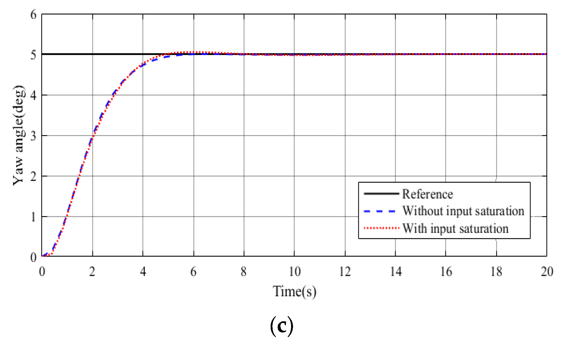
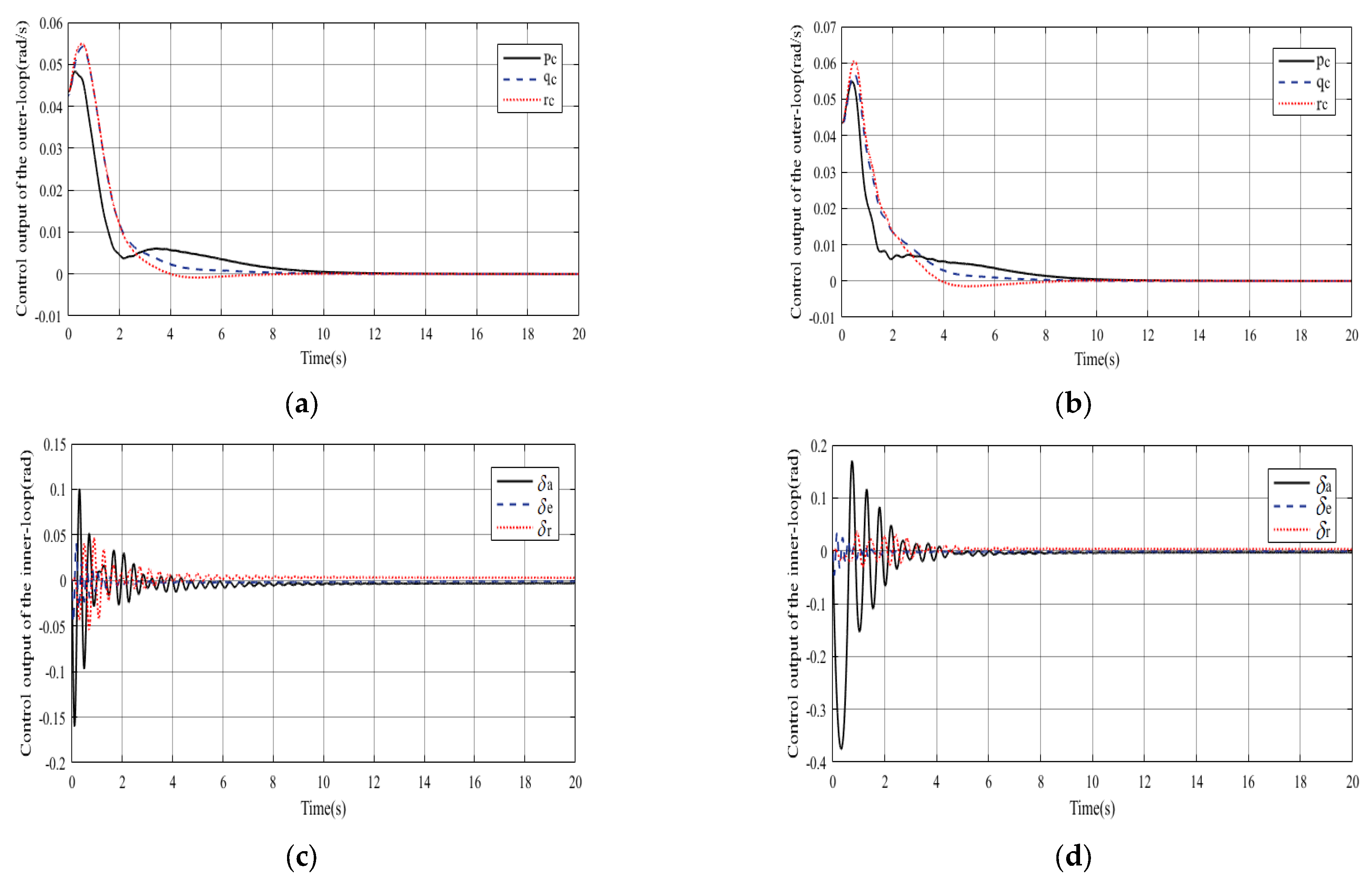
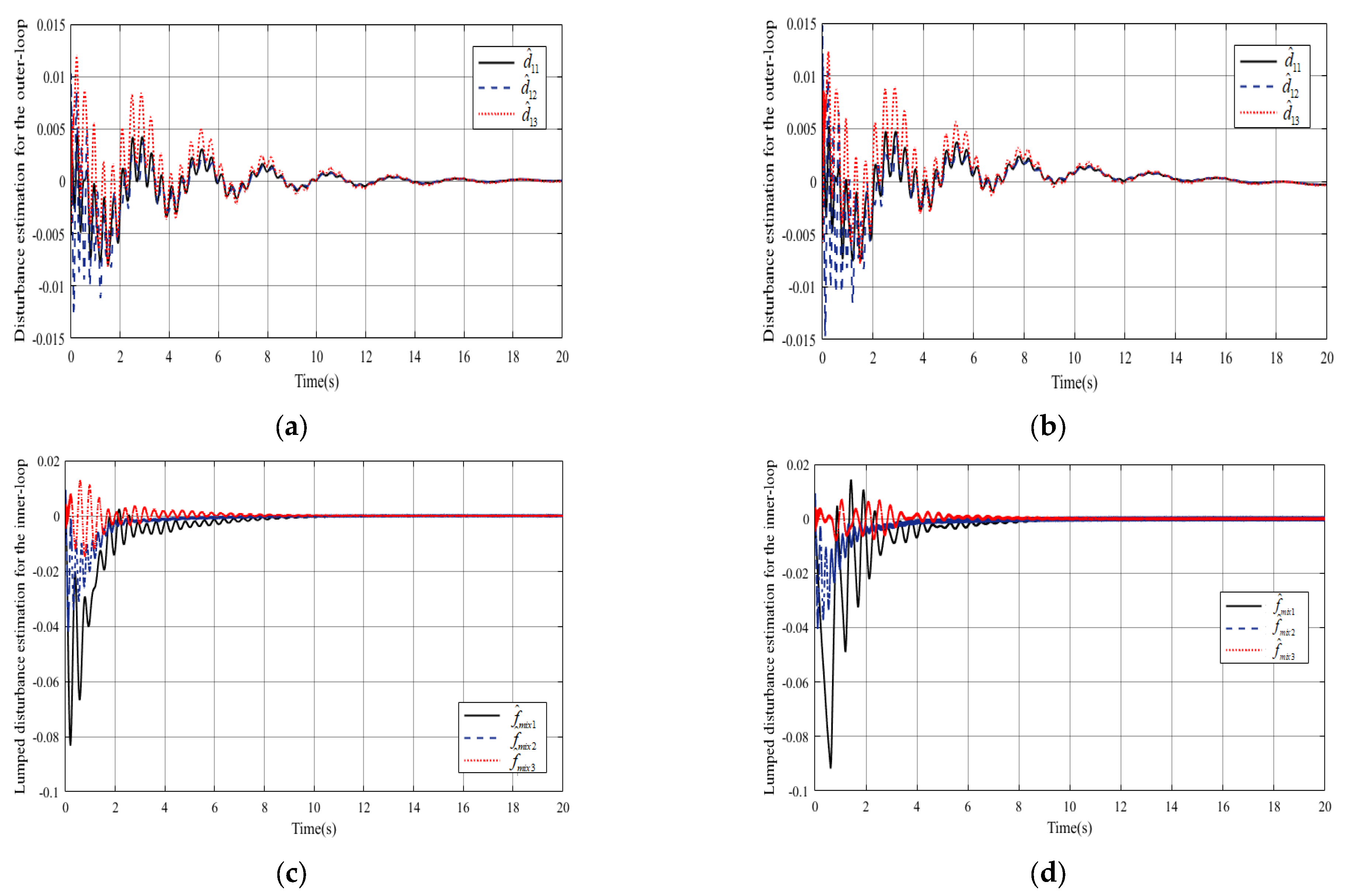
Figure 3 presents the tracking performance of the designed NNDONDI-L1 controller under both conditions of control input without and with saturation. As can be seen from Figure 3a–c, the tracking response curves of each attitude angle are extremely similar regardless of whether they are subject to input saturation or not, which all track up to the given reference signal in a short time and have no overshoot or oscillation. The indicator values in Table 2 also validate the above conclusions. Control output signals and disturbance estimation curves of the designed controller are shown in Figure 4 and Figure 5, all of which are uniformly bounded. From Figure 3, Figure 4 and Figure 5 and Table 2, it can be seen that the designed NNDONDI-L1 controller eliminates the effect of the control input saturation and has excellent anti-saturation ability.
The jamming immunity and fault tolerance of the proposed NNDONDI-L1 controller is verified by comparing with NDI-L1 and NNDONDI-MRAC in the following scenarios 2 and 3. The parameters and simulation conditions of MRAC are the same as those of the L1 adaptive controller.
  • Scenario 2. System subject to input saturation and external disturbances.
The saturation constraints for the control input signals are set as in scenario 1. The external disturbances are considered as follows:
d 2 = 0 t < 10 , 0.1 + 0.5 sin t , 0.3 + sin 2 t , 0.5 + 1.5 sin 3 t T ; 10 t < 13 , 0.2 , 0.2 , 0.2 T ; t 13 , sin 0.1 t , cos 0.2 t , sin 0.5 t T .
The external disturbance model includes externally differentiable time-varying disturbances and non-differentiable constant disturbances. The UAV system is subject to time-varying and constant composite disturbances in 0 t < 10 s . To better simulate actual flight conditions, the composite disturbance is modeled as a variable amplitude and variable frequency form. At the 10th second, a pulse disturbance signal with an amplitude of 0.2 N and a duration of 3 s is injected to simulate a sudden gust of wind from outside. After the 13th second, the UAV is affected by time-varying disturbances again. Next, comparative simulation experiments based on NNDONDI-L1 (the proposed control scheme), NDI-L1, and NNDONDI-MRAC are performed simultaneously to verify the effectiveness and advantages of the proposed controller. Note that MRAC was selected as a comparison controller in order to verify the superiority of L1 adaptive control as a variant of MRAC in eliminating undesirable oscillations caused by high gains and improving system robustness. Similarly, NDI-L1 is also chosen to verify the effectiveness of NNDO.
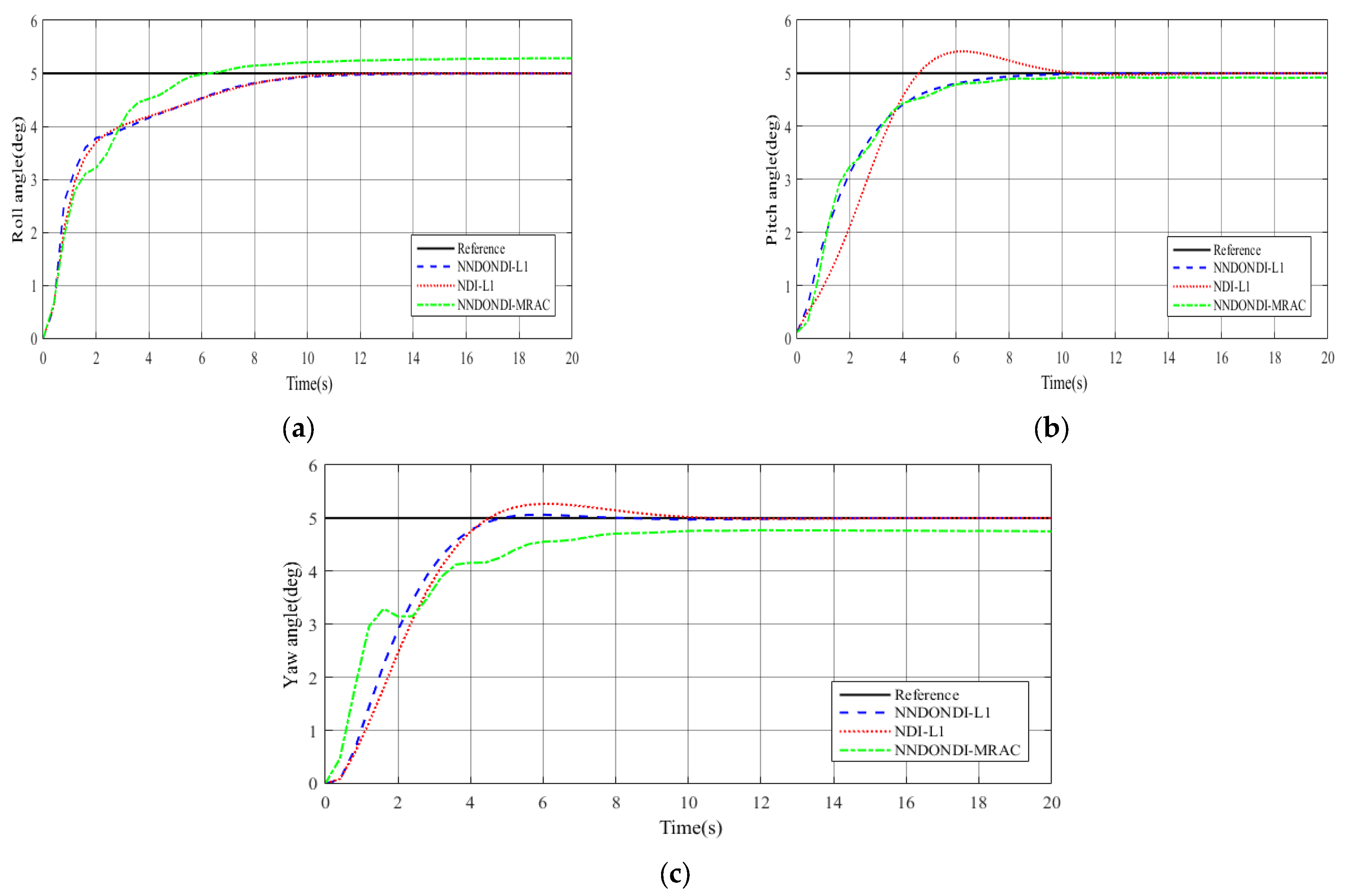
The comparative simulation results are shown in Figure 6, Figure 7 and Figure 8. Figure 6a–c illustrates the tracking response curves for the three attitude angles with input saturation and external disturbances. It is clearly seen that the proposed NNDONDI-L1 controller is more resistant to disturbances and has better tracking performance compared to the other two comparison controllers under the same simulation conditions, achieving smallest tracking error and convergence time, as well as minimum overshoot. The detailed performance metrics and their quantitative analysis are all given in Table 3 and Table 4. From the performance indicators and their analysis, it can be seen that the proposed NNDONDI-L1 controller has higher accuracy, better stability and faster convergence time in tracking the three attitude angles compared to NDI-L1 and NNDONDI-MRAC, even though the external disturbances cause all the metrics to be a bit larger than in scenario 1. This is more evident in the roll angle channel and the yaw angle channel. For instance, the roll and yaw angle convergence times of NNDONDI-L1 are 10.6281 s and 10.0135 s, which are 12.3% and 7.6% lower than NDI-L1, respectively, whereas NNDONDI-MRAC converges in more than 20 s (denoted by “—”), with the slowest convergence rates and largest tracking errors.
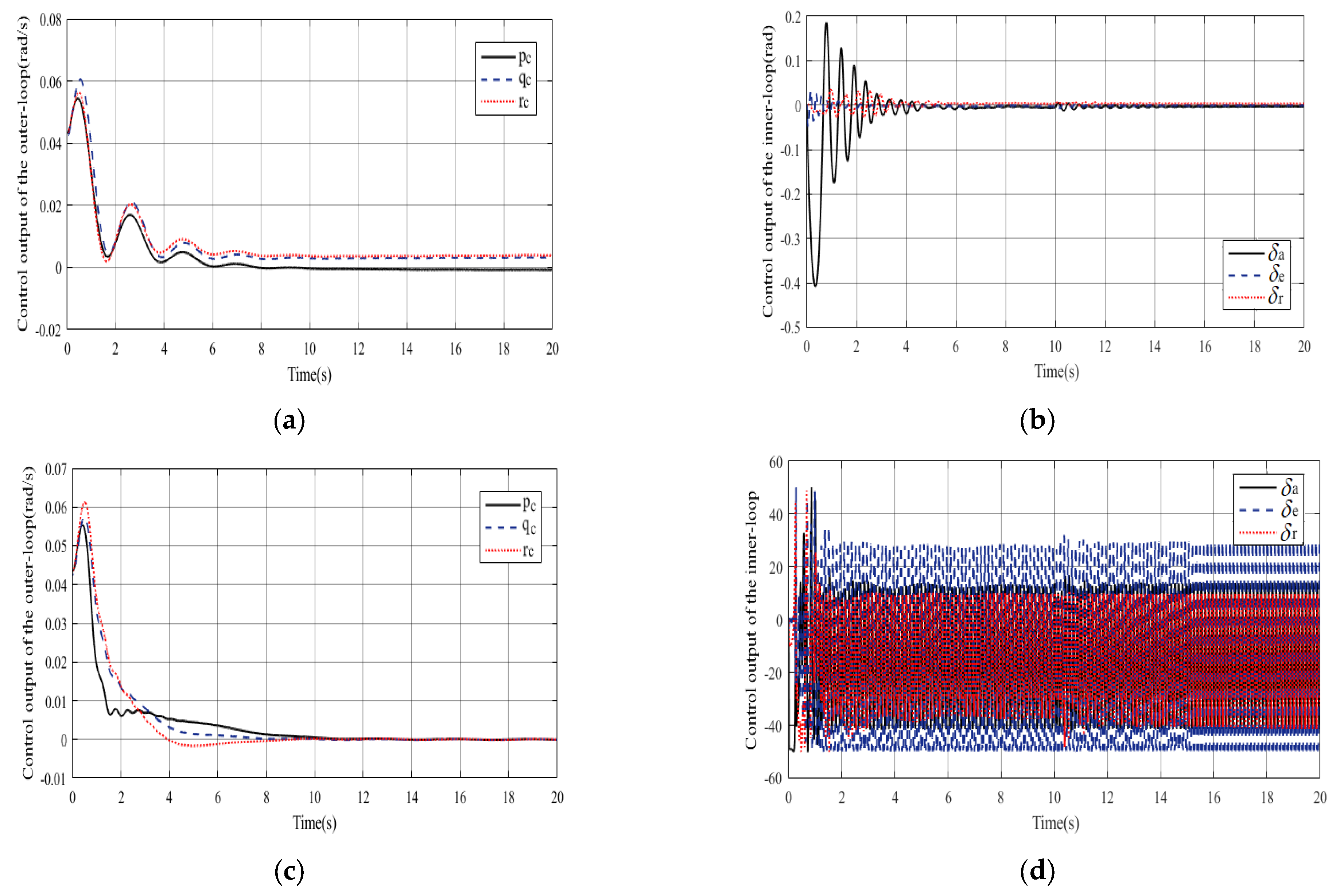
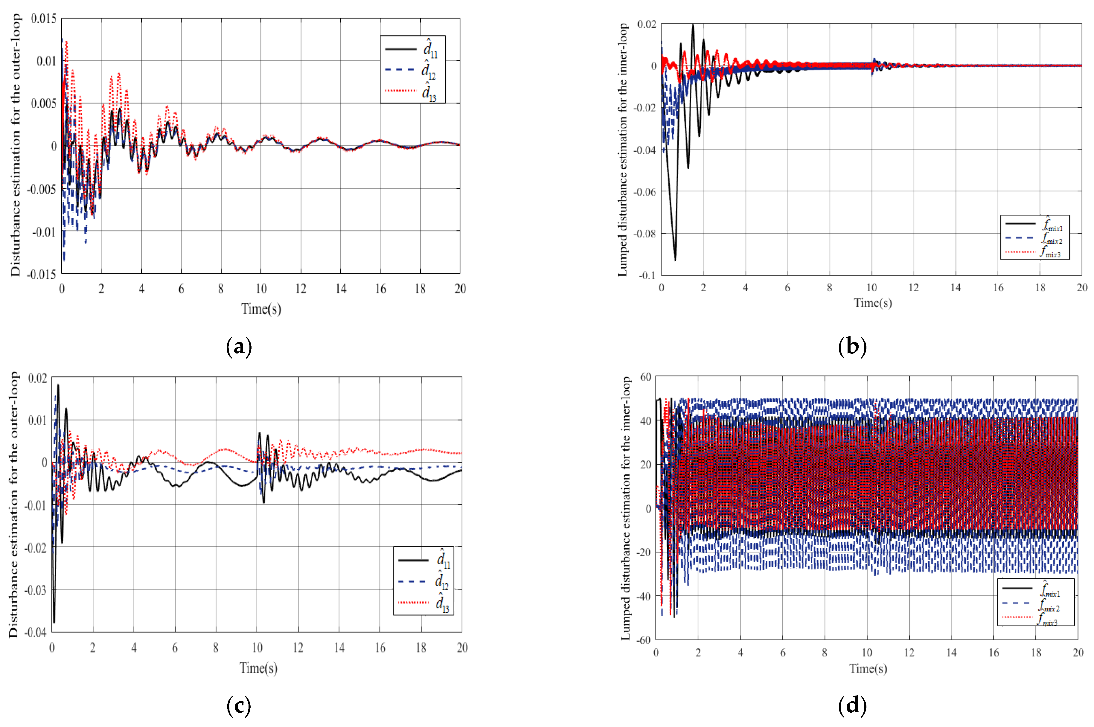
In order to verify the advantages of L1 adaptive control algorithms over MRAC in eliminating high-frequency oscillations, the inner- and outer-loop control output signals of the NNDONDI-L1 controller and the NNDONDI-MRAC controller are demonstrated in Figure 7, and the disturbance estimation responses are shown in Figure 8. It is clear to see that all control outputs and disturbance estimates are guaranteed to be convergent and bounded despite the presence of input saturation and external disturbances. From Figure 7b,d, it can be seen that the designed L1 adaptive controller significantly suppresses the high-frequency oscillations due to high gains in the MRAC controller, as well as Figure 8b,d.
  • Scenario 3. System subject to input saturation, external disturbances, and actuator faults.
In order to verify the fault-tolerance and robustness of the proposed NNDONDI-L1 controller, actuator faults are introduced on the basis of scenarios 1 and 2. The saturation constraints and external disturbances are set as in scenarios 1 and 2. Actuator faults are considered as
0 t < 8 , ω = d i a g 0.5 , 0.7 , 1 , v a = d i a g 0 , 0 , 0 ; 8 t < 12 , ω = d i a g 0.8 , 0.3 , 0.2 t , v a = d i a g 0.1 + 0.5 sin t , 0.5 0.1 t , 3 cos 0.1 t ; t 12 , ω = d i a g 1 , 1 , 1 , v a = d i a g 0 , 0 , 0 .
The fault model indicates that the UAV suffers constant LOE faults on control surfaces of elevator and aileron in 0 t < 8 s ; a hybrid fault consisting of time-varying LOE faults and additive faults occurs on control surfaces of elevator, aileron, and rudder in 8 t < 12 s ; all actuators return to normal operation after t = 12 s . Note that the above fault models include constant and time-varying LOE (multiplicative faults), constant or periodic time-varying or non-periodic time-varying additive faults, but do not involve unmodeled actuator faults. At the same time, the occurrence and duration of faults are preset to simulate actual fault conditions.
The comparative simulation results of NNDONDI-L1, NDI-L1, and NNDONDI-MRAC are shown in Figure 9, Figure 10 and Figure 11. The performance metrics for each attitude angle and their quantitative analysis are given in Table 5 and Table 6. A comparison of Figure 6 and Figure 9 shows that the constant LOE faults in 0 t < 8 s have little effect on attitude angle tracking, but the hybrid fault with time-varying LOE faults and additive faults in 8 t < 12 s cause large fluctuations in the tracking curves. In the beginning, all three controllers are able to overcome the effects of the constant LOE faults well. When the hybrid fault occurs at the 8th second, the NNDONDI-L1 controller compensates its effect well and tracks up the reference signal quickly with minimum overshoot and settling time; the steady-state errors of the three channels of the attitude angles are less than 0.02; and the convergence time is between 10 and 17 s, while the steady-state errors of the three channels of the comparative NDI-L1 and NNDONDI-MRAC controllers both exceed 0.02 in some cases, especially for NNDONDI-MRAC, and none of them can be converged in less than 20 s. As can be seen from Figure 9, and Table 5 and Table 6, the stability, convergence, and tracking performance of the designed NNDONDI-L1 controller are much better than the other two comparative controllers when actuator faults occur.
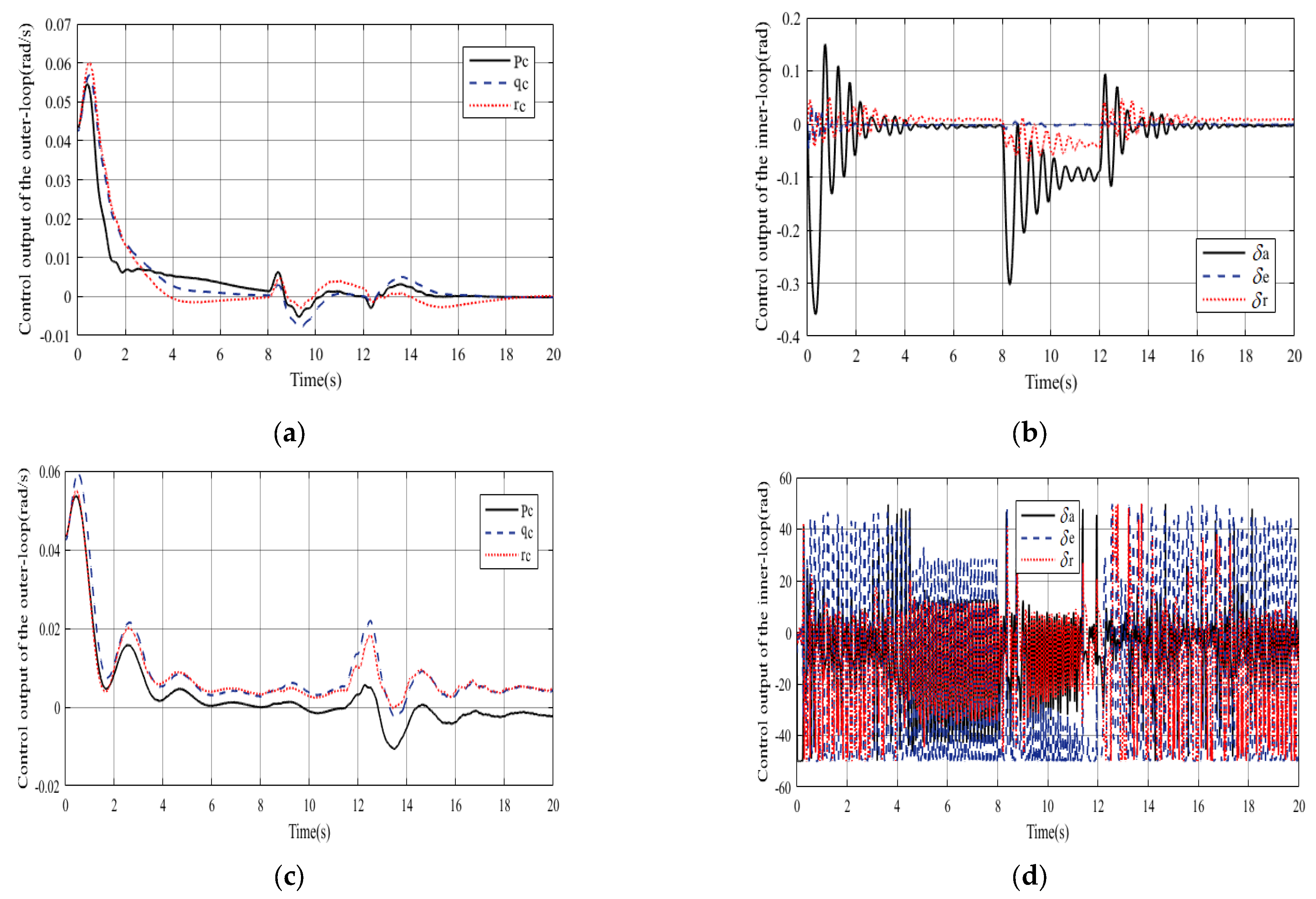
The control output signals and disturbance estimation curves for the inner and outer loops of NNDONDI-L1 and NNDONDI-MRAC controllers are demonstrated in Figure 10 and Figure 11. There are large fluctuations in the control output responses and disturbance estimation curves at the moments of faults occurrence and removal; both the NNDONDI-L1 and NNDONDI-MRAC controllers can eliminate the undesired fluctuations caused by faults and maintain uniform boundedness. Compared to NNDONDI-MRAC, the designed NNDONDI-L1 controller has smaller fluctuations and shorter convergence times in the various response curves of scenarios 2 and 3 (i.e., Figure 6, Figure 7, Figure 8, Figure 9, Figure 10 and Figure 11), and thus, has stronger fault-tolerance and robustness.

5. Conclusions

A fault-tolerant controller based on NNDONDI and L1 adaptive algorithm is explored for the UAV attitude control system subject to input saturation, external disturbances, and actuator faults, and its stability and performance bounds are derived. The outer loop NDI controller with an NNDO not only guarantees fast response but also reduces the dependence on model accuracy. The inner loop L1 adaptive controller eliminates the effect of system uncertainties through online estimation of the lumped uncertainty. The response curves and quantitative analysis of indicators under three scenarios demonstrate that the proposed NNDONDI-L1 fault-tolerant control scheme can effectively handle and compensate for input saturation, external disturbances, and actuator faults with highlighted anti-disturbance and fault-tolerance. Compared to NDI-L1 and NNDONDI-MRAC, all metrics for three attitude angles of the designed NNDONDI-L1 are optimized in scenarios 2 and 3 (from Table 3 and Table 5), with a maximum improvement of 63.1% relative to NDI-L1 and a maximum improvement of 78.2% relative to NNDONDI-MRAC (scenario 2); and a maximum improvement of 67.6% relative to NDI-L1 and a maximum improvement of 70.6% relative to NNDONDI-MRAC (scenario 3). Designing FTC schemes that take into account unmodeled actuator faults and dynamics, and time delays is one of the future works. Also, the finite-time convergence problem of NNDO is a direction for performance improvement.

Author Contributions

Conceptualization, Y.Z.; methodology, H.L.; software, Y.L.; validation, J.L. and Y.Z.; formal analysis, Y.Z.; writing—original draft preparation, Y.L. and J.L.; writing—review and editing, Y.Z. All authors have read and agreed to the published version of the manuscript.

Funding

This research received no external funding.

Data Availability Statement

Data are contained within the article.

Conflicts of Interest

The authors declare no conflicts of interest.

References

  1. Abbaspour, A.; Yen, K.K.; Forouzannezhad, P.; Sargolzaei, A. A neural adaptive approach for active fault-tolerant control design in UAV. IEEE Trans. Syst. Man Cybern. Syst. 2020, 50, 3401–3411. [Google Scholar] [CrossRef]
  2. Mallavalli, S.; Fekih, A. A fault tolerant tracking control for a quadrotor UAV subject to simultaneous actuator faults and exogenous disturbances. Int. J. Control 2020, 93, 655–668. [Google Scholar] [CrossRef]
  3. Nguyen, N.P.; Pitakwachara, P. Integral terminal sliding mode fault tolerant control of quadcopter UAV systems. Sci. Rep. 2024, 14, 10786. [Google Scholar] [CrossRef] [PubMed]
  4. Yu, W.; Yan, J.; Pan, X.H.; Tan, S.L.; Cao, H.W.; Song, Y.D. Fault-tolerant attitude tracking control with practical finite time convergence for unmanned aerial vehicles under actuation faults. Int. J. Robust Nonlinear Control 2022, 32, 3737–3753. [Google Scholar] [CrossRef]
  5. Li, W.; Yang, P.; Geng, K.K.; Zhu, X.Y. Fault-tolerant attitude tracking control of tandem rotor helicopter considering internal actuator saturation and external wind gust. Int. J. Adapt. Control Signal Process. 2023, 37, 1671–1692. [Google Scholar] [CrossRef]
  6. Duan, H.B.; Yuan, Y.; Zeng, Z.G. Distributed cooperative control of multiple UAVs in the presence of actuator faults and input constraints. IEEE Trans. Circuits Syst. II Express Briefs 2022, 69, 4463–4467. [Google Scholar] [CrossRef]
  7. Yu, Z.L.; Li, Y.H.; Lv, M.L.; Pei, B.B.; Fu, A.Q. Event-triggered adaptive fuzzy fault-tolerant attitude control for tailless flying-wing UAV with fixed-time convergence. IEEE Trans. Veh. Technol. 2024, 73, 4858–4869. [Google Scholar] [CrossRef]
  8. Shen, Q.; Yue, C.F.; Goh, C.H.; Wang, D.W. Active fault-tolerant control system design for spacecraft attitude maneuvers with actuator saturation and faults. IEEE Trans. Ind. Electron. 2019, 66, 3763–3772. [Google Scholar] [CrossRef]
  9. Wang, X.H.; Tan, C.P.; Wu, F.; Wang, J.D. Fault-tolerant attitude control for rigid spacecraft without angular velocity measurements. IEEE Trans. Cybern. 2021, 51, 1216–1229. [Google Scholar] [CrossRef]
  10. Zhang, S.J.; Han, W.H.; Zhang, Y.M. Finite time convergence incremental nonlinear dynamic inversion-based attitude control for flying-wing aircraft with actuator faults. Actuators 2020, 9, 70. [Google Scholar] [CrossRef]
  11. Zhu, G.B.; Ma, Y.; Li, Z.X.; Malekian, R.; Sotelo, M. Event-triggered adaptive neural fault-tolerant control of underactuated MSVs with input saturation. IEEE Trans. Intell. Transp. Syst. 2022, 23, 7045–7057. [Google Scholar] [CrossRef]
  12. Liang, H.J.; Liu, G.L.; Huang, T.W.; Lam, H.K.; Wang, B.H. Cooperative fault-tolerant control for networks of stochastic nonlinear systems with nondifferential saturation nonlinearity. IEEE Trans. Syst. Man Cybern. Syst. 2022, 52, 1362–1372. [Google Scholar] [CrossRef]
  13. Meng, Y.Z.; Liu, C.; Liu, Y.L. Adaptive attitude angle constrained fault-tolerant control of hypersonic vehicle with unknown centroid shift. Aerosp. Sci. Technol. 2023, 140, 108475. [Google Scholar] [CrossRef]
  14. Chen, M.; Yan, K.; Wu, Q.X. Multiapproximator-based fault-tolerant tracking control for unmanned autonomous helicopter with input saturation. IEEE Trans. Syst. Man Cybern. Syst. 2022, 52, 5710–5722. [Google Scholar] [CrossRef]
  15. Yu, Z.Q.; Liu, Z.X.; Zhang, Y.M.; Qu, Y.H.; Su, C.Y. Distributed finite-time fault-tolerant containment control for multiple unmanned aerial vehicles. IEEE Trans. Neural Netw. Learn. Syst. 2020, 31, 2077–2091. [Google Scholar] [CrossRef]
  16. Li, B.; Gong, W.Q.; Yang, Y.S.; Xiao, B.; Ran, D.C. Appointed fixed time observer-based sliding mode control for a quadrotor UAV under external disturbances. IEEE Trans. Aerosp. Electron. Syst. 2022, 58, 290–303. [Google Scholar] [CrossRef]
  17. Zhao, Z.H.; Cao, D.; Yang, J.; Wang, H.M. High-order sliding mode observer-based trajectory tracking control for a quadrotor UAV with uncertain dynamics. Nonlinear Dynam 2020, 102, 2583–2596. [Google Scholar] [CrossRef]
  18. Hu, Y.P.; Guo, J.; Ying, P.; Zeng, G.N.; Chen, N.Y. Nonlinear control of a single tail tilt servomotor tri-rotor ducted VTOL-UAV. Aerospace 2022, 9, 296. [Google Scholar] [CrossRef]
  19. Emami, S.A.; Banazadeh, A.; Hajipourzadeh, P.; Castaldi, P.; Fazelzadeh, S.A. Disturbance observer-based adaptive neural guidance and control of an aircraft using composite learning. Control Eng. Pract. 2023, 134, 105463. [Google Scholar] [CrossRef]
  20. Lungu, M. Auto-landing of UAVs with variable centre of mass using the backstepping and dynamic inversion control. Aerosp. Sci. Technol. 2020, 103, 105912. [Google Scholar] [CrossRef]
  21. Lv, J.X.; Wang, C.H.; Kao, Y.G. Adaptive fixed-time quantized fault-tolerant attitude control for hypersonic reentry vehicle. Neurocomputing 2023, 520, 386–399. [Google Scholar] [CrossRef]
  22. Liu, S.Q.; Whidborne, J.F. Observer-based incremental backstepping sliding-mode fault-tolerant control for blended-wing-body aircrafts. Neurocomputing 2021, 464, 546–561. [Google Scholar] [CrossRef]
  23. Rong, Y.F.; Chou, W.S.; Jiao, R. Robust fault-tolerant motion/force control of a fully-actuated hexarotor using adaptive sliding mode impedance control. Int. J. Robust Nonlinear Control 2022, 32, 4149–4172. [Google Scholar] [CrossRef]
  24. Kong, C.Y.; Zhao, D.J.; Dai, M.Z.; Liang, B.G. ESO-based event-triggered attitude control of spacecraft with unknown actuator faults. Adv. Space Res. 2023, 71, 768–784. [Google Scholar] [CrossRef]
  25. Cai, X.; Zhu, X.Z.; Yao, W. FTESO-adaptive neural network based safety control for a quadrotor UAV under multiple disturbances: Algorithm and experiments. Ind. Robot. 2024, 51, 20–33. [Google Scholar] [CrossRef]
  26. Xu, X.F.; Chen, M.; Li, T.; Wu, Q.X. Composite fault tolerant attitude control for flexible satellite system under disturbance and input delay. Appl. Math. Comput. 2021, 409, 126419. [Google Scholar] [CrossRef]
  27. Shen, Y.X.; Zhou, D.J.; Wu, Y.D.; Huang, D.W. Anti-disturbance control for HVs system subject to nonlinear actuator characteristics with extended state observer. J. Frankl. Inst. 2023, 360, 14676–14695. [Google Scholar] [CrossRef]
  28. Mazare, M. Reconfigurable tolerant control of nonlinear Euler-Lagrange systems under actuator fault: A reinforcement learning-based fixed-time approach. Aerosp. Sci. Technol. 2023, 142, 108631. [Google Scholar] [CrossRef]
  29. Sanwale, J.; Dahiya, S.; Trivedi, P.; Kothari, M. Robust fault-tolerant adaptive integral dynamic sliding mode control using finite-time disturbance observer for coaxial octorotor UAVs. Control Eng. Pract. 2023, 135, 105495. [Google Scholar] [CrossRef]
  30. Cao, C.Y.; Hovakimyan, N. Design and analysis of a novel L1 adaptive controller, part I: Control signal and asymptotic stability. In Proceedings of the 2006 American Control Conference, Minneapolis, MN, USA, 14–16 June 2006; pp. 3397–3402. [Google Scholar] [CrossRef]
  31. Meng, X.F.; Zhang, G.C.; Han, B. Fault-tolerant control of underactuated MSVs based on neural finite-time disturbance observer: An Event-triggered Mechanism. J. Frankl. Inst. 2024, 361, 106603. [Google Scholar] [CrossRef]
  32. Hazem, Z.B.; Saidi, F.; Guler, N.; Altaif, A.H. Reinforcement learning-based intelligent trajectory tracking for a 5-DOF Mitsubishi robotic arm: Comparative evaluation of DDPG, LC-DDPG, and TD3-ADX. Int. J. Intell. Robot. Appl. 2025. [Google Scholar] [CrossRef]
  33. Liu, H.; Li, B.; Xiao, B.; Ran, D.C.; Zhang, C.X. Reinforcement learning-based tracking control for a quadrotor unmanned aerial vehicle under external disturbances. Int. J. Robust Nonlinear Control 2023, 33, 10360–10377. [Google Scholar] [CrossRef]
  34. Durham, W.C.; Lutze, F.H. Perfect explicit model-following control solution to imperfect model-following control-problems. J. Guid. Control Dynam 1991, 14, 391–397. [Google Scholar] [CrossRef]
  35. Pomet, J.B.; Praly, L. Adaptive nonlinear regulation: Estimation from Lyapunov equation. IEEE Trans. Autom. Control. 1992, 37, 729–740. [Google Scholar] [CrossRef]
  36. Yousef, H.A.; Hamdy, M.; Nashed, K. L1 adaptive fuzzy controller for a class of nonlinear systems with unknown backlash-like hysteresis. Int. J. Syst. Sci. 2017, 48, 2522–2533. [Google Scholar] [CrossRef]
  37. Li, Z.Y.; Shi, S.; Liu, H. Trajectory tracking of tail-sitter aircraft by adaptive fault tolerant control. J. Syst. Eng. Electron. 2021, 32, 1477–1489. [Google Scholar] [CrossRef]
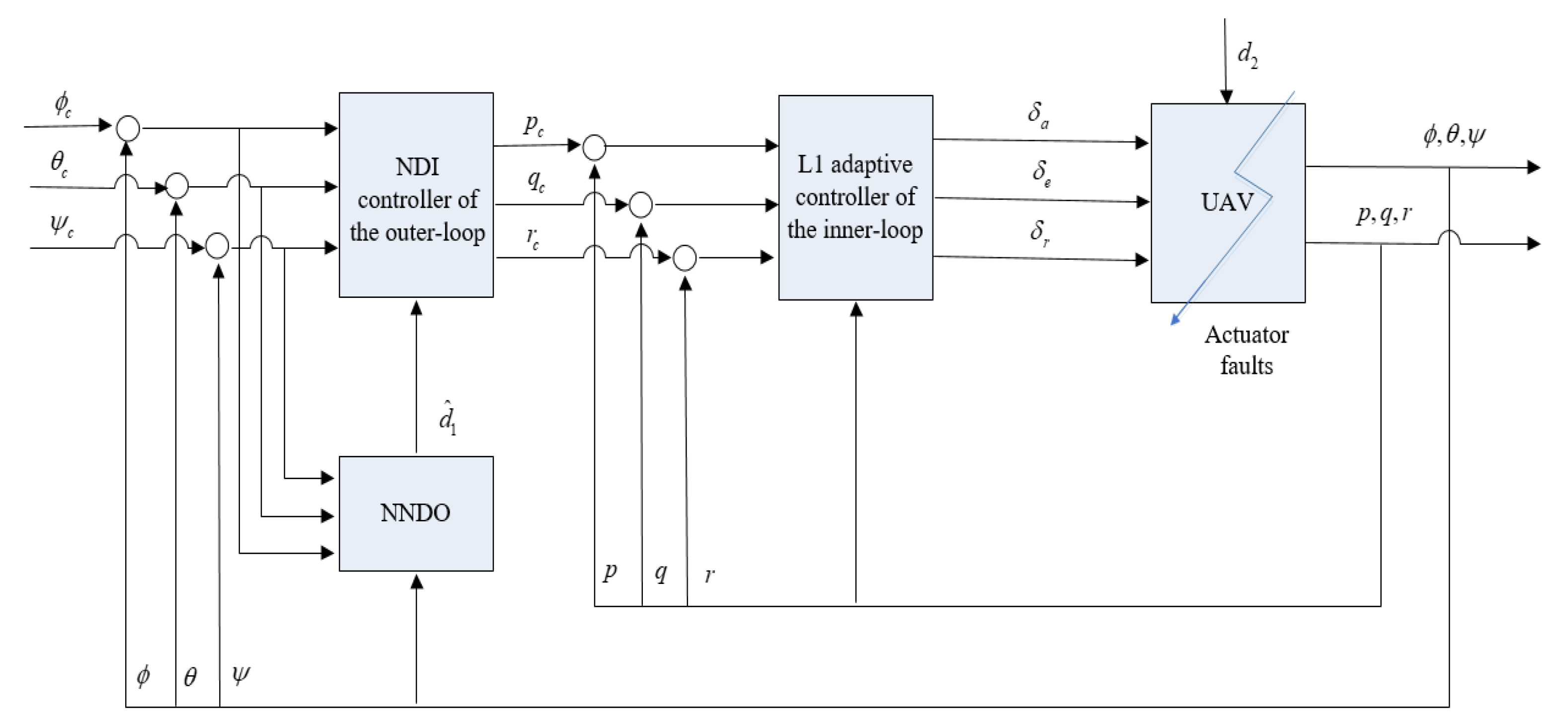
Figure 1. Overall block diagram of the proposed fault-tolerant controller.
Actuators 14 00437 g001
Figure 2. The response curves for s a t ( v 2 ) and h ( v 2 ) .
Actuators 14 00437 g002
Figure 3. Tracking performance of NNDONDI-L1 controller. (a) Tracking curves of roll angle; (b) tracking curves of pitch angle; (c) tracking curves of yaw angle.
Actuators 14 00437 g003aActuators 14 00437 g003b
Figure 4. Control output curves of NNDONDI-L1 controller. (a) Control outputs of the outer loop without input saturation; (b) control outputs of the outer loop with input saturation; (c) control outputs of the inner loop without input saturation; (d) control outputs of the inner loop with input saturation.
Actuators 14 00437 g004
Figure 5. Disturbance estimation curves of NNDONDI-L1 controller. (a) Disturbance estimations for the outer loop without input saturation; (b) disturbance estimations for the outer loop with input saturation; (c) lumped disturbance estimations for the inner loop without input saturation; (d) lumped disturbance estimations for the inner loop with input saturation.
Actuators 14 00437 g005
Figure 6. Tracking performance in scenario 2. (a) Tracking curves of roll angle; (b) tracking curves of pitch angle; (c) tracking curves of yaw angle.
Actuators 14 00437 g006
Figure 7. Control output curves in scenario 2. (a) Control outputs of the outer loop of the proposed NNDONDI-L1 controller; (b) control outputs of the inner loop of the proposed NNDONDI-L1 controller; (c) control outputs of the outer loop of NNDONDI-MRAC controller; (d) control outputs of the inner loop of NNDONDI-MRAC controller.
Actuators 14 00437 g007
Figure 8. Disturbance estimation curves in scenario 2. (a) Disturbance estimations for the outer loop of the proposed NNDONDI-L1 controller; (b) disturbance estimations for the inner loop of the proposed NNDONDI-L1 controller; (c) disturbance estimations for the outer loop of NNDONDI-MRAC controller; (d) disturbance estimations for the inner loop of NNDONDI-MRAC controller.
Actuators 14 00437 g008
Figure 9. Tracking performance in scenario 3. (a) Tracking curves of roll angle; (b) tracking curves of pitch angle; (c) tracking curves of yaw angle.
Actuators 14 00437 g009
Figure 10. Control output curves in scenario 3. (a) Control outputs of the outer loop of the proposed NNDONDI-L1 controller; (b) control outputs of the inner loop of the proposed NNDONDI-L1 controller; (c) control outputs of the outer loop of NNDONDI-MRAC controller; (d) control outputs of the inner loop of NNDONDI-MRAC controller.
Actuators 14 00437 g010
Figure 11. Disturbance estimation curves in scenario 3. (a) Disturbance estimations for the outer loop of the proposed NNDONDI-L1 controller; (b) disturbance estimations for the inner loop of the proposed NNDONDI-L1 controller; (c) disturbance estimations for the outer loop of NNDONDI-MRAC controller; (d) disturbance estimations for the inner loop of NNDONDI-MRAC controller.
Actuators 14 00437 g011
Table 1. Parameters and their descriptions of UAVs.
System ParametersDescriptions
ϕ , θ , ψ attitude angles of roll, pitch, and yaw
p , q , r attitude angle velocities of roll, pitch, and yaw
L , M , N moments of roll, pitch, and yaw
c 1 to   c 9 coefficients
Q dynamic pressure
S w reference area of the wing
b span of the wing
c A mean geometric chord length of the wing
α angle of attack
β angle of sideslip
C l , C m , C n aerodynamic coefficients
δ a , δ e , δ r deflection angles of aileron, elevator, and rudder
Table 2. Performance indicators of attitude angles in scenario 1.
Attitude AnglesIndicatorsWithout Input SaturationWith Input Saturation
Roll anglesteady-state error0.00050.0006
convergence time9.15259.153
IAE0.16850.1684
ISE0.00630.0064
ITAE0.4260.4203
ITSE0.00640.0064
Pitch anglesteady-state error0.00010.0001
convergence time6.93087.1491
IAE0.17170.1719
ISE0.00820.0082
ITAE0.29250.3047
ITSE0.00750.0076
Yaw anglesteady-state error0.00040.0002
convergence time4.67114.3802
IAE0.1690.1726
ISE0.01030.0103
ITAE0.22880.2416
ITSE0.00890.0089
Table 3. Performance indicators of attitude angles in scenario 2.
Attitude AnglesIndicatorsNNDONDI-L1NDI-L1NNDONDI-MRAC
Roll anglesteady-state error0.00060.00090.2853
convergence time10.628112.1248
IAE0.16830.17080.2014
ISE0.00640.00770.0072
ITAE0.41930.42480.9848
ITSE0.00640.00730.0093
Pitch anglesteady-state error0.00010.00110.0181
convergence time9.78711.10288.8169
IAE0.1720.26790.1948
ISE0.00810.01490.0087
ITAE0.30730.67480.5653
ITSE0.00760.02060.0083
Yaw anglesteady-state error0.00010.00140.248
convergence time10.013510.8314
IAE0.17360.20290.2389
ISE0.01030.01160.0112
ITAE0.24610.37241.129
ITSE0.00890.01160.0119
Table 4. Comparative analysis of performance indicators in scenario 2.
Attitude AnglesIndicatorsAnalysis
Roll angleIAEMinimum IAE: 0.1683(NNDONDI-L1), 1.5% lower than NDI-L1, 16.4% lower than NNDONDI-MRAC
ISEMinimum ISE: 0.0064(NNDONDI-L1), 16.9% lower than NDI-L1, 11.1% lower than NNDONDI-MRAC
ITAEMinimum ITAE: 0.4193(NNDONDI-L1), 1.3% lower than NDI-L1, 57.4% lower than NNDONDI-MRAC
ITSEMinimum ITSE: 0.0064(NNDONDI-L1), 12.3% lower than NDI-L1, 31.2% lower than NNDONDI-MRAC
Pitch angleIAEMinimum IAE: 0.172(NNDONDI-L1), 35.8% lower than NDI-L1, 11.7% lower than NNDONDI-MRAC
ISEMinimum ISE: 0.0081(NNDONDI-L1), 45.6% lower than NDI-L1, 6.9% lower than NNDONDI-MRAC
ITAEMinimum ITAE: 0.3073(NNDONDI-L1), 54.5% lower than NDI-L1, 45.6% lower than NNDONDI-MRAC
ITSEMinimum ITSE: 0.0076(NNDONDI-L1), 63.1% lower than NDI-L1, 8.4% lower than NNDONDI-MRAC
Yaw angleIAEMinimum IAE: 0.1736(NNDONDI-L1), 14.4% lower than NDI-L1, 27.3% lower than NNDONDI-MRAC
ISEMinimum ISE: 0.0103(NNDONDI-L1), 11.2% lower than NDI-L1, 8% lower than NNDONDI-MRAC
ITAEMinimum ITAE: 0.2461(NNDONDI-L1), 33.9% lower than NDI-L1, 78.2% lower than NNDONDI-MRAC
ITSEMinimum ITSE: 0.0089(NNDONDI-L1), 23.3% lower than NDI-L1, 25.2% lower than NNDONDI-MRAC
Table 5. Performance indicators of attitude angles in scenario 3.
Attitude AnglesIndicatorsNNDONDI-L1NDI-L1NNDONDI-MRAC
Roll anglesteady-state error0.00130.00140.2974
convergence time10.610210.6123
IAE0.17220.18550.23
ISE0.00640.0080.0071
ITAE0.46740.56341.338
ITSE0.00650.01040.0185
Pitch anglesteady-state error0.00650.00680.089
convergence time15.937415.942
IAE0.19260.27910.2135
ISE0.00810.01530.0087
ITAE0.56850.72010.779
ITSE0.00830.02560.0282
Yaw anglesteady-state error0.01860.02180.253
convergence time17.239918.3102
IAE0.20830.24320.2509
ISE0.01050.01180.0181
ITAE0.68930.88261.276
ITSE0.01090.01450.0212
Table 6. Comparative analysis of performance indicators in scenario 3.
Attitude AnglesIndicatorsAnalysis
Roll angleIAEMinimum IAE: 0.1722(NNDONDI-L1), 7.2% lower than NDI-L1, 25.1% lower than NNDONDI-MRAC
ISEMinimum ISE: 0.0064(NNDONDI-L1), 20% lower than NDI-L1, 9.9% lower than NNDONDI-MRAC
ITAEMinimum ITAE: 0.4674(NNDONDI-L1), 17% lower than NDI-L1, 65.1% lower than NNDONDI-MRAC
ITSEMinimum ITSE: 0.0065(NNDONDI-L1), 37.5% lower than NDI-L1, 64.9% lower than NNDONDI-MRAC
Pitch angleIAEMinimum IAE: 0.1926(NNDONDI-L1), 30.1% lower than NDI-L1, 9.8% lower than NNDONDI-MRAC
ISEMinimum ISE: 0.0081(NNDONDI-L1), 47.1% lower than NDI-L1, 6.9% lower than NNDONDI-MRAC
ITAEMinimum ITAE: 0.5685(NNDONDI-L1), 21.1% lower than NDI-L1, 27% lower than NNDONDI-MRAC
ITSEMinimum ITSE: 0.0083(NNDONDI-L1), 67.6% lower than NDI-L1, 70.6% lower than NNDONDI-MRAC
Yaw angleIAEMinimum IAE: 0.2083(NNDONDI-L1), 14.4% lower than NDI-L1, 17% lower than NNDONDI-MRAC
ISEMinimum ISE: 0.0105(NNDONDI-L1), 11% lower than NDI-L1, 42% lower than NNDONDI-MRAC
ITAEMinimum ITAE: 0.6893(NNDONDI-L1), 21.9% lower than NDI-L1, 46% lower than NNDONDI-MRAC
ITSEMinimum ITSE: 0.0109(NNDONDI-L1), 24.8% lower than NDI-L1, 48.6% lower than NNDONDI-MRAC
Disclaimer/Publisher’s Note: The statements, opinions and data contained in all publications are solely those of the individual author(s) and contributor(s) and not of MDPI and/or the editor(s). MDPI and/or the editor(s) disclaim responsibility for any injury to people or property resulting from any ideas, methods, instructions or products referred to in the content.