Article

Multibody Dynamics Simulation of Upper Extremity Rehabilitation Exoskeleton During Task-Oriented Exercises

by
Piotr Falkowski
* and
Krzysztof Zawalski
Łukasiewicz Research Network—Industrial Research Institute for Automation and Measurements PIAP, 02-486 Warsaw, Poland
*
Author to whom correspondence should be addressed.
Actuators 2025, 14(9), 426; https://doi.org/10.3390/act14090426
Submission received: 18 July 2025 / Revised: 26 August 2025 / Accepted: 28 August 2025 / Published: 30 August 2025
(This article belongs to the Special Issue Advances in Intelligent Control of Actuator Systems)

Abstract

Population aging intensifies the demand for rehabilitation services, which are already suffering from staff shortages. In response to this challenge, the implementation of new technologies in physiotherapy is needed. For such a task, rehabilitation exoskeletons can be used. While designing such tools, their functionality and safety must be ensured. Therefore, simulations of their strength and kinematics must meet set criteria. This paper aims to present a methodology for simulating the dynamics of rehabilitation exoskeletons during activities of daily living and determining the reactions in the construction’s joints, as well as the required driving torques. The methodology is applied to the SmartEx-Home exoskeleton. Two versions of a multibody model were developed in the Matlab/Simulink environment—a rigid-only version and one with deformable components. The kinematic chain of construction was reflected with the driven rotational joints and modeled passive sliding open bearings. The simulation outputs include the driving torques and joint reaction forces and the torques for various input trajectories registered using IMU sensors on human participants. The results obtained in the investigation show that in general, to mobilize shoulder flexion/extension or abduction/adduction, around 30 Nm of torque is required in such a lightweight exoskeleton. For elbow flexion/extension, around 10 Nm of torque is needed. All of the reactions are presented in tables for all of the characteristic points on the passive and active joints, as well as the attachments of the extremities. This methodology provides realistic load estimations and can be universally used for similar structures. The presented numerical results can be used as the basis for a strength analysis and motor or force sensor selection. They will be directly implemented for the process of mass minimization of the SmartEx-Home exoskeleton based on computational optimization.

1. Introduction

It is estimated that the number of people over the age of 65 will double and reach approximately 1.6 billion by 2050 [1]. This increased life expectancy results from improved quality of healthcare, sanitation conditions, and general socio-economic development. Part of this growth is a consequence of rising survival rates in early life, significantly impacting the demographic structure of societies in individual countries worldwide [1]. Moreover, the risk of chronic diseases will increase directly in proportion to the average age. As a result, the demand for healthcare services will increase [2], while healthcare systems suffer from staff shortages [3].
The development of new technologies and their introduction into active use will be crucial for the quality and quantity of healthcare services provided [4]. Intelligent medical devices have the potential to improve the quality of healthcare significantly. With modern functionalities, they can monitor patients’ health in real time, reducing the time of hospitalization [5]. One example of such devices, dedicated to physiotherapy, is rehabilitation robots. These can be used by patients with neurological injuries such as stroke, spinal cord damage, and cerebral palsy [6].
Assistive technologies must meet functional requirements in order to achieve their task—increasing the independent social participation of treated patients, involving support in activities of daily living (ADLs) [7,8]. ADLs are fundamental in the rehabilitation of individuals with various functional limitations. These include basic tasks such as eating (snacking and sipping), dressing, grooming, mobility, and managing one’s daily responsibilities (also related to work) [9,10,11]. The assessment of ADLs is also important for specialists, as it provides information about the challenges faced by individuals with mobility or cognitive limitations [12]. This information enables more precise customization support and interventions into the changing needs of patients based on potential compensations or non-functional motion patterns [13]. ADLs performed as exercises are applicable for kinesiotherapy, particularly in task-oriented treatment [14]. Such a process can be realised with the use of rehabilitation robots [15,16].
Rehabilitation robots for the upper extremities are already used in medical practice. They differ mainly in terms of their kinematic structure, their capacity for relocation, and the type of therapy they enable [15,17]. This can include passive support or resistance, active assistance, and even more complex approaches, such as error enhancement [18] and the generation of personalized motion perturbations [19]. Moreover, they are likely to be connected with additional technologies supporting therapy—virtual reality and teleoperation tools, among others [20]. New approaches to therapy and robot designs are continuously being developed, which proves that they are an emerging trend for future physiotherapy [15,21,22]. Nevertheless, using simulations based on real-life registered motion within the design process is not common yet [23].
Among rehabilitation robots, exoskeletons are effective for multijoint task-oriented therapy, as they are capable of mobilizing and monitoring multiple degrees of freedom (DOFs) correlated with the real motion of segments of the body [13]. They can guide a limb in a precisely planned manner, replicating the natural movement and resultant loads at characteristic points, such as attachments of the extremities or modeled centers of the joints [24]. Thanks to their mechanical structure, exoskeletons effectively support users in performing rehabilitation exercises [25], assist in regaining the ability to move independently [26], and aid in functioning with limited mobility, thereby improving quality of life [27].
As wearables, exoskeletons benefit from minimizing their mass while meeting functional criteria [28]. Therefore, within the design process, complex simulations are used to confirm the sufficient strength of a design while performing real-life motions under real-life loads. So far, a simulation-based approach involving multibody dynamic models has mainly been used with exoskeletons for gait treatment [29]. The gait process is already well modeled [30]; on the contrary, the activities of daily living performed using the upper extremities differ significantly [13]. Therefore, designing an exoskeleton for task-oriented physiotherapy for the upper extremities requires simulations that are strongly dependent on the selected motions to be supported.
This paper aims to present a universal low-cost methodology for simulating the motion of a rehabilitation exoskeleton for the upper extremities based on the real-life therapeutic ADLs. This includes an analysis of the internal loads at characteristic points, which can be used to perform a strength analysis and numerically optimize the structure of the construction, along with determining the required driving torques. The methodology can be used universally for different exoskeletons, while the constructed multibody dynamics (MBD) models can also be reused for treatment planning [31]. Moreover, the results of simulations are applicable to the universal design of lightweight exoskeletons for the upper extremities as the reference loads and torques.
This paper is structured into five sections. Section 2 presents the methodology of the investigations, including the desired outputs, the workflow of the experiments, the kinematic structure of a simulated exoskeleton, and the tools used for the simulation and analyses. Section 3 describes the multibody model constructed with real-life registered input signals, the model setup, the presentation of the selected submodel, the structures and joints used, the method for creating deformable bodies, and computation of the simulation outputs. Section 4 refers to results in terms of the required actuating torques and critical reaction loads and a comparison of non-deformable and partially flexible models. The last section is focused on the conclusions drawn and the potential applicability of the presented methodology to broader research.

2. Methodology

Simulations were performed to compute two types of output based on real-life motion. The outputs included
  • The torque values required to achieve the desired dynamics during the execution of planned movements;
  • The actual internal loads within the joints of the structure.
To acquire them, the following steps were performed:
  • Recording real-life ADLs, used in the simulations as the input trajectories (described in the complementary paper [13]);
  • Constructing a rigid multibody model that reflects the designed structure;
  • Performing simulations to compute the outputs;
  • Selecting extreme combinations of loads in the structures and extreme driving torques;
  • Preparing “.rom” (Reduced Order Model) files and meshes for key structural elements, which enable the deformations in these elements within the motion to be computed;
  • Constructing a flexible multibody model for selected components and analyzing the impact of deformations on the mechanical structure.
This section presents a real-life representation of the model constructed in the presented case study and the tools used for the complex simulation. As the key element of the investigation, the construction of the multibody model will be presented in the following section.

2.1. The Exoskeleton

All of the simulations were performed for the exoskeleton of the upper extremities SmartEx-Home [13]. Only the exoskeleton itself, without its mobile platform, was considered within the investigation. This device is suitable for users ranging from the 5th female percentile to the 95th male percentile of the Polish population [32]. The structure includes five anatomical degrees of freedom (DOFs)—three active and two passive (shoulder and elbow external/internal rotations). Additionally, two length adjustments were implemented to align with the lengths of the arm and the forearm. The maximum ranges of motion for the DOFs correspond to the actual anatomical ranges of motion, as shown in the Table 1. The main bodies of the device are made of Aluminium 6061, mostly 3D-printed. Only the sliding bearings are manufactured from polymers. The upper extremity can be attached to the exoskeleton using two elastic straps in the arm and forearm regions. Figure 1 presents the exoskeleton design used to build the simulation model, while Table 2 contains descriptions of the subcomponents.
Body 1 serves as the attachment point for the structure to a specialized mounting frame. It is connected with Body 2 by a rotational joint driven by an electric motor. Likewise, Bodies 2 and 3 are connected with the same type of joint. They provide shoulder flexion/extension, combined with abduction/adduction. A passive degree of freedom connecting Bodies 3 and 4 is responsible for the internal/external rotation of the shoulder joint. Together, these three DOFs cover the full range of motion of the shoulder joint.
The movements in the elbow joint are enabled by the next two joints. Bodies 5 and 6 are connected by the rotational joint, which enables elbow flexion/extension. The second passive degree of freedom, connecting Bodies 6 and 7, enables the last anatomical movement considered—external/internal rotation of the elbow. The interfaces of Body 4 with Body 5 and Body 7 with Body 8 enable linear adjustment of the exoskeleton’s structure. Thanks to them, it can be adapted to a user’s individual anatomy.
As mentioned, a patient’s extremity is attached to the exoskeleton using two elastic straps. These can be offset with the distance blocks to align the axes of the real-life upper extremity with the exoskeleton’s operational axis. All of the joints, length adjustments, and points of attachment of the extremity to the exoskeleton are the characteristic points of the model. For each of them, the reaction loads are determined.
For the simulations, it was assumed that the exoskeleton axes perfectly aligned with the axes of the extremity (as in theory, such an adjustment is possible) and that the shoulder and elbow joints were ball and hinge joints. Additionally, single-DOF rotation of the forearm is assumed. The wrist joint remained moving freely, as it was not attached to the exoskeleton. All of the exercise trajectories used with the exoskeleton were recorded by physiotherapists applying the therapeutic motions used in practice.

2.2. Tools

To perform the tasks described in this section, the following tools were involved:
  • Movella DOT—Measurement units and software used for data collection;
  • Autodesk Inventor 2021—CAD software for preparing the exoskeleton design;
  • Matlab 2024a—Engineering software used to create the simulation model;
  • Simulink—The block diagram environment for model-based design within MATLAB;
  • Simscape—A tool for modeling and simulating physical systems;
  • Simscape Multibody—A specialized toolbox within Simscape, designed for modeling and simulating the mechanics of 3D systems;
  • Signal Processing Toolbox—A package that provides tools for analyzing, designing, and simulating signal processing systems;
  • Robotic System Toolbox—Enables the design, simulation, and control of robotics systems;
  • Partial Differential Equation Toolbox—Provides functions for solving partial differential equations, utilized for “.rom” file generation.

3. The Model

3.1. Model Inputs

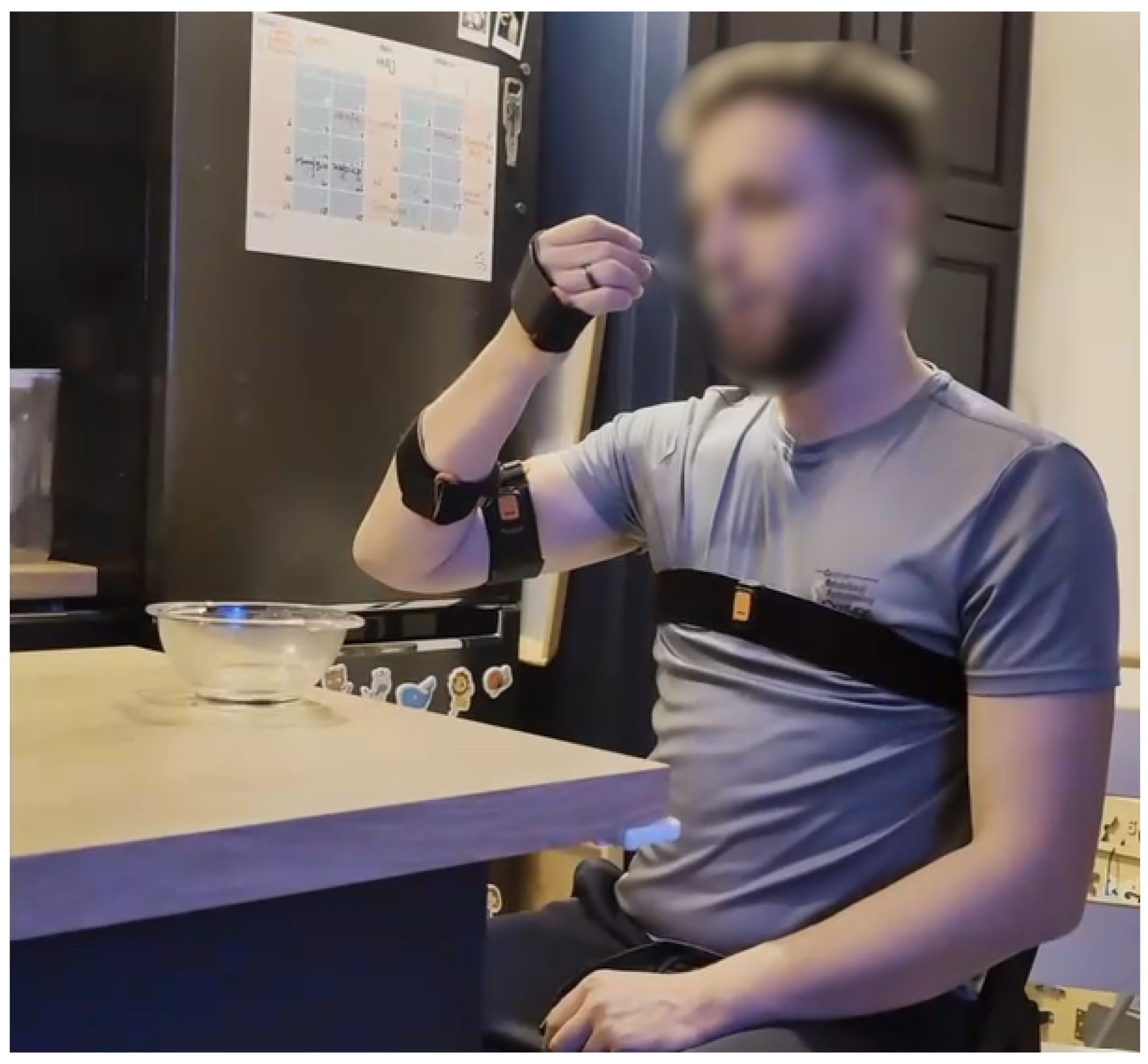
The model in the simulation moves based on the joint trajectories imposed on the exoskeleton’s joints. To obtain them, measurements of real-life movements were performed. Twenty-two ADLs were selected for the data collection process. The recording process and the list of motions are presented in the complementary paper [13]. The particular motions were chosen as the most frequently and repetitively performed ADLs by healthy individuals and those with mobility impairments. Figure 2 exhibits the exemplary measurement process for the trajectory “Eating with a spoon”.
The recorded data were then processed into trajectories corresponding to human joints using the original software described in the complementary paper [13]. The result of this process is a set of joint trajectories for the five rotational joints of the exoskeleton. Figure 3 shows an example of the joint trajectories for the movement of taking an object out of a drawer (only part of the time series is visualised to increase clarity).
Trajectory control required processing the input time series with the use of the Polynomial Trajectory block and the Clock block for synchronization. The B-spline method generated continuous trajectories based on the discrete time series for specified time intervals.
Thanks to the use of the actual trajectories, it was possible to achieve realistic and precise results, which increased the effectiveness of the simulation and allowed actual upper limb movements to be mimicked in the model.

3.2. Model Initialization

Upon the launch of the simulation, scripts are automatically executed, delivering the variables used by the model into the working environment and enabling user interaction with the model. The executed scripts are
  • A script that enables the selection of a recorded trajectory from each patient to be used in the simulation.
  • A script importing a mechanical model—the paths to the files representing the mechanical components are automatically adjusted to the location of the main folder where the simulation file “.slx” and all other data regarding the 43 solid models of all of the exoskeleton design subcomponents are stored.
  • A script that processes and loads the trajectories as the input to the system. First, the trajectory is read from the “.csv” file, followed by splitting it into appropriate vectors and matrices to ensure dimensional consistency of the variables for the correct operation of the model with each trajectory used. The variable defining the duration of the simulation is also defined here by reading the maximum value from the time column.
  • An optional script used for deformable simulations, which assigns the deformable elements to the model.

3.3. Model Configuration

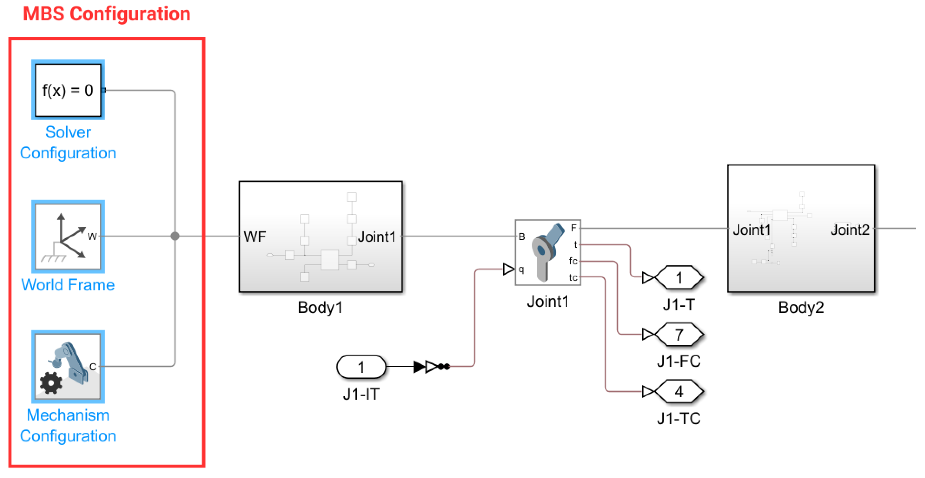
The simulation begins with three blocks that define the Solver Configuration, the world frame, and the Mechanism Configuration (see Figure 4).
The first block allows the appropriate solver settings used for the simulation to be configured. This includes the accuracy, the type of equation-solving method applied, and the buffer size for delays.
The second block provides access to the global, unique, stationary, orthogonal, right-handed coordinate system. The global coordinate system serves as the basis for all reference frame networks in the model. In the case of multiple global drainage system blocks, all refer to a single point in space.
The third block sets the mechanical and simulation parameters that apply to the entire machine to which the block is connected. Among others, it defines uniform gravitational acceleration for the entire mechanism.

3.4. The Subsystem Structure

Every simulation starts from the same base configuration, reflecting the extremity’s configuration at the beginning of recording the ADLs. Figure 5 shows the rigid version of the simulation at time t = 0 , in a configuration adjusted to a user corresponding to the 95th percentile of the Polish male population [32], as the most impactful on the internal loads and driving torques [23].
The simulations presented in this paper were performed before mass minimization, held as the continuation of research. To compute the dynamics, the masses of the parts in the models were sourced from CAD models and the anatomical models of the extremity [33]. These were based on anthropometric dimensional and mass data [32] and the relationship between these and the inertia parameters [34]. They were assigned to the model subcomponents in the modeled centers of mass. The masses of the particular components of the simulation model (corresponding to selected exoskeleton parts and segments of the user’s extremity) are presented in Table 3. The total mass of the simulated system (including extremity) is 11.85 kg.
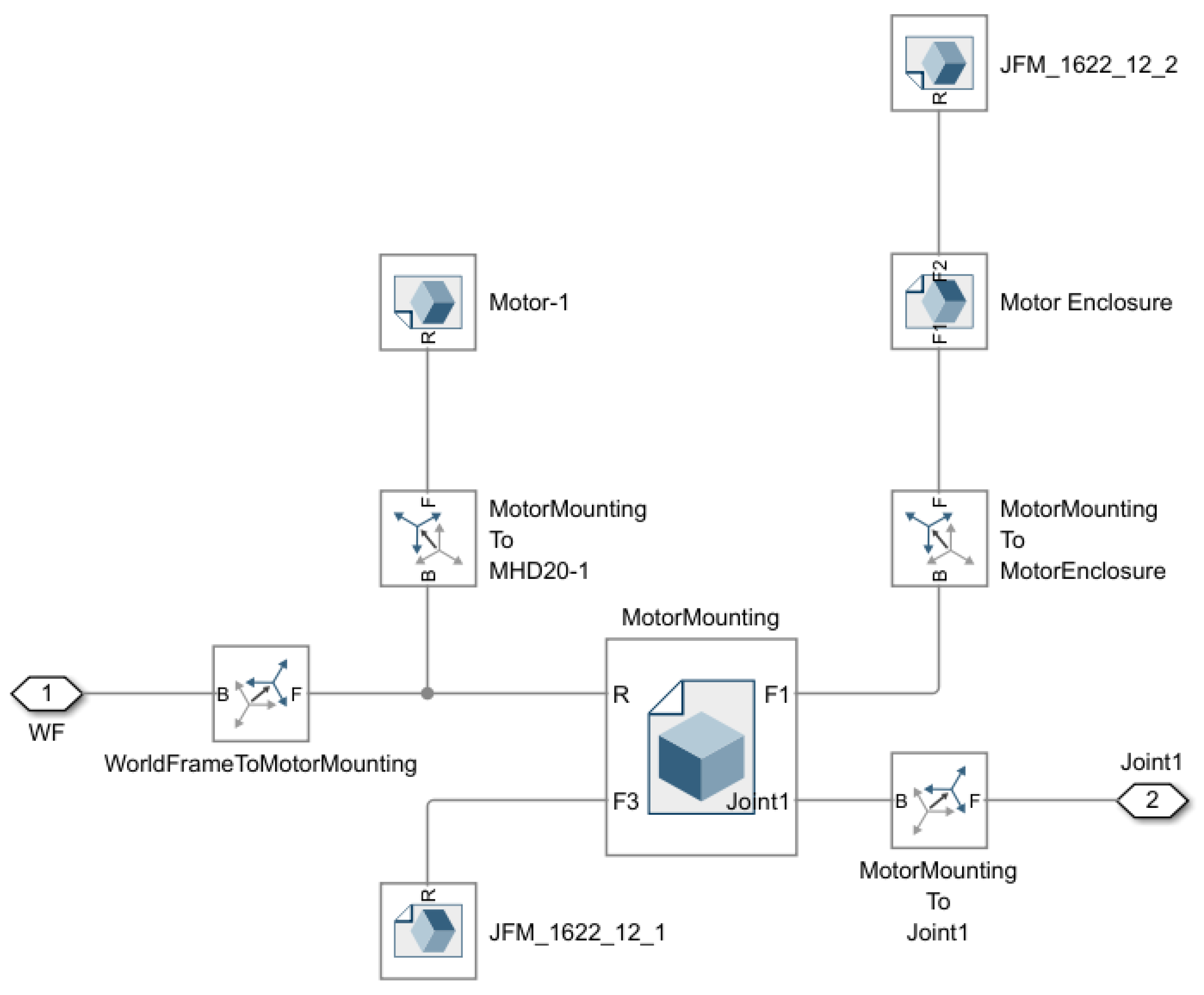
The following blocks of the simulated mechanism are connected to those previously described. Manipulation of the position of individual mechanical parts that make up the model is carried out through the “Rigid Transform” blocks [30]. The solids are represented by “File Solid” blocks. The geometry, material properties, mechanical properties, and coordinate systems are sourced from the CAD file. Every part of the model (mentioned in Table 3) is connected either to the world frame or to another part with a joint. Therefore, each of them is wrapped in a subsystem—an example of such is illustrated in Figure 6.

3.5. Joint Structure

Rotational joints of the exoskeleton are modeled using “Revolute Joint” blocks. The stiffness and damping coefficients of the internal spring-damper force law for the joint primitive were experimentally chosen so that the degree of freedom applied reflected reality, taking into account inaccuracies and energy losses due to friction. In order to select the appropriate values for the coefficients, a mathematical pendulum was modeled using the “Revolute Joint” block. Then, the trajectory results were compared with the experimental results [35].
The chosen method of actuation assumes position as the input value to the simulation. The driving torque is calculated and exported as one of the system’s outputs. In Figure 4, the port J1-IT (Joint 1—Input Trajectory) delivers the driving trajectory to the joint, and through the port J1-T (Joint 1—Torque), the required driving torque is exported.
The remaining two measurements read from the joint are the reaction forces and torques acting upon the joint during the system’s operation. These are also the simulated system outputs. They are exported via the ports J1-FC (Joint 1—Force Constraint) and J1-TC (Joint 1—Torque Constraint).
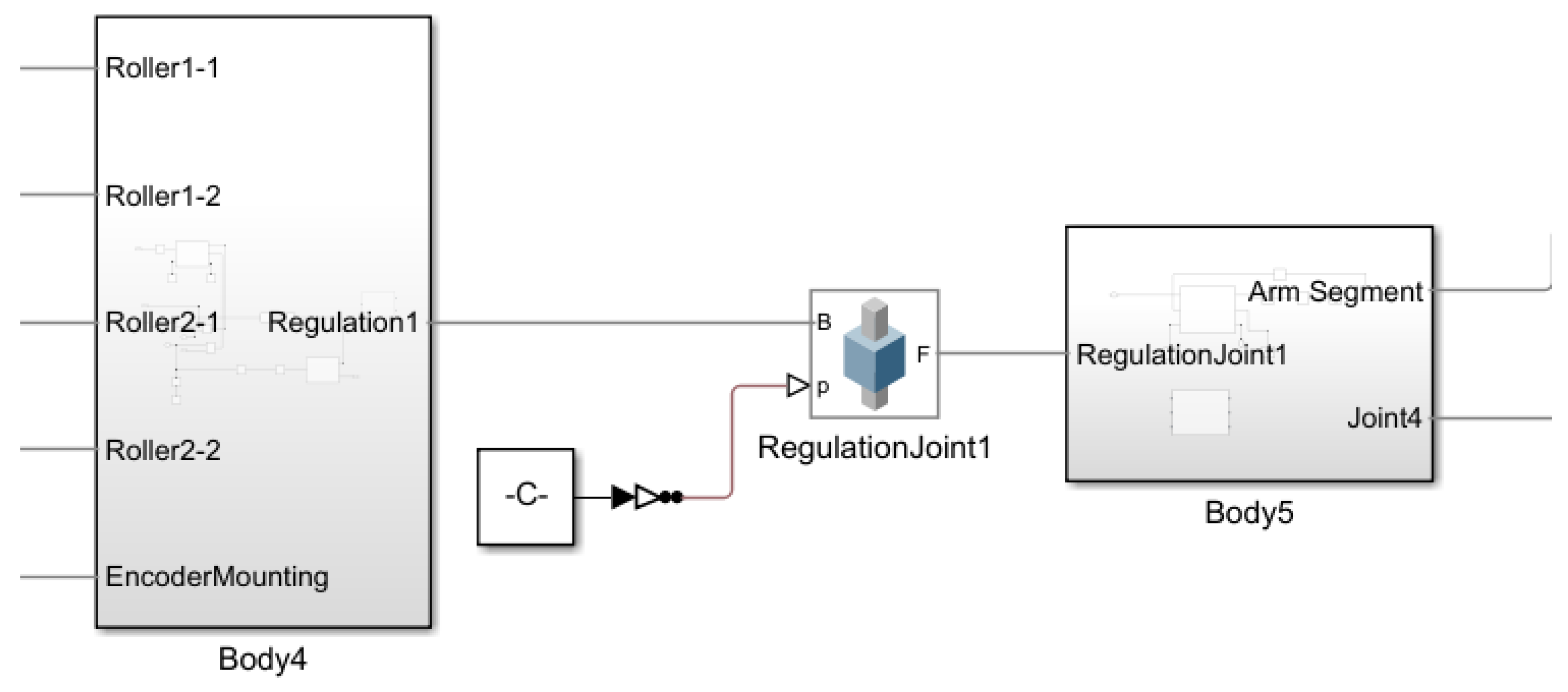
Linear adjustments are modeled using the “Prismatic Joint” blocks. The input values to these joints are set as constants for the whole simulation and are variable based on the user’s anatomy. An example of such a joint is presented in Figure 7.

3.5.1. Extremity Attachment

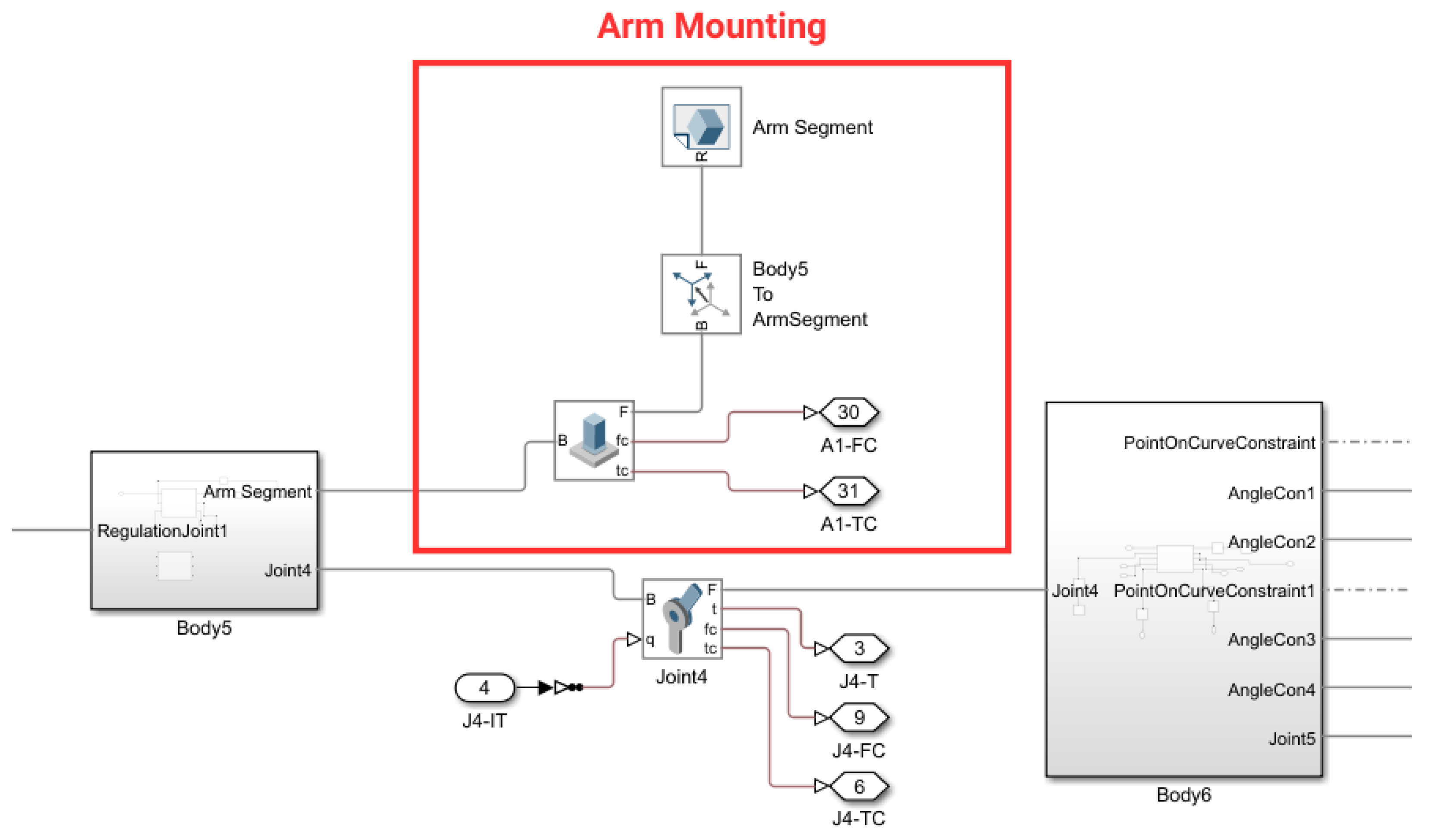
The simulated system also includes an upper extremity model imposing the actual loads resulting from inertia during the exercises. Figure 8 shows the connection to the exoskeleton structure. A “Welded Joint” block was used to simulate the attachment of the extremity to the elastic straps. The mounting points of these fixed joints correspond to the actual location of the parts responsible for attaching the upper limb to the structure. Additional transformation blocks were used to correctly position the upper limb model regarding the attached segment. An example of such a structure used to attach an arm to Body 5 is visualized in Figure 8.

3.5.2. Free Sliding Bearings

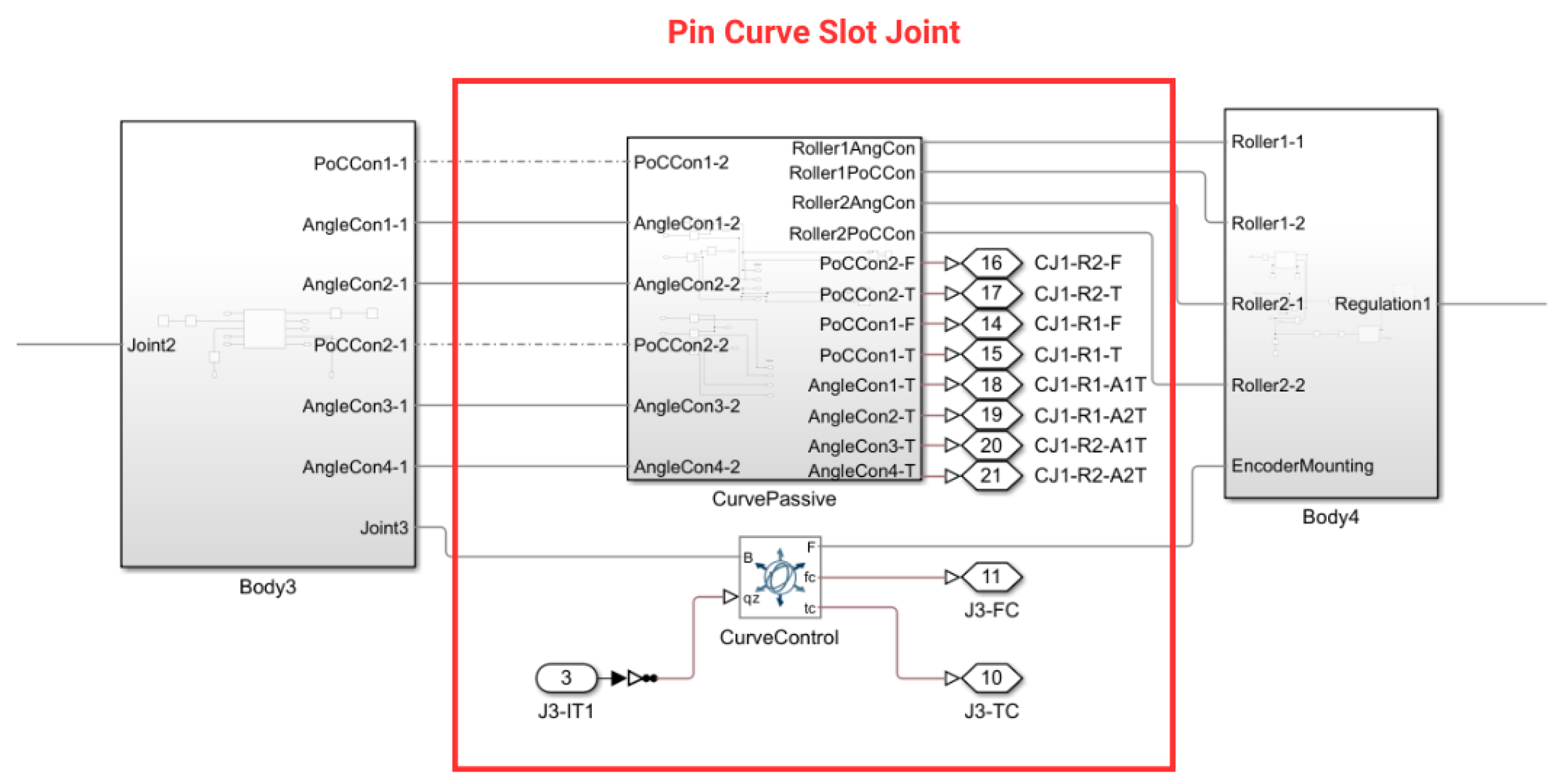
As part of the project, free sliding bearings (passive joints) were modeled using a pin curve slot mechanism driven by rotations exerted by a user intentionally. In this submodel (presented in Figure 9), the curves along which each roller moves are semicircles, defined as two separate splines.
The following constraints were applied separately to each roller to achieve the proper effect:
  • PointOnCurveConstraint—This enforces the movement of the assigned coordinate system of the roller along the curve. The forces and reaction torques resulting from maintaining the specified point on the defined curve are measured.
  • Angle Constraint 1—This enforces the maintenance of a particular angle within the range of ( 0 ; 180 ) degrees between the Z-axes of the base and the follower coordinate systems. In this case, the movement around the X-axis of the coordinate system is restricted, and the angle is set to 90 degrees. The only value measured is the reaction torque resulting from the applied constraint.
  • Angle Constraint 2—Similarly, this enforces the maintenance of the angle value between the Z-axes. In this case, the movement around the Y-axis of the coordinate system is restricted. The measured quantity is the same as that in Angle Constraint 1, but the reaction torque is measured around a different axis.
After applying the described constraints, the rollers move freely along the curve. Connecting them to the next part restricts their movement relative to each other. Rotational degrees of freedom have been implemented at the connection points to give the attached part the desired mobility, thereby enabling internal/external rotations of the shoulder and elbow joints.
To enable control of the mechanism, a “6 DOF Joint” block has been implemented between the connected parts. Thus, no additional constraints are added; instead, a control method is enabled, similar to the case of revolute joints. The input trajectory is provided in the same way as that for revolute joints.

3.6. Deformable Bodies

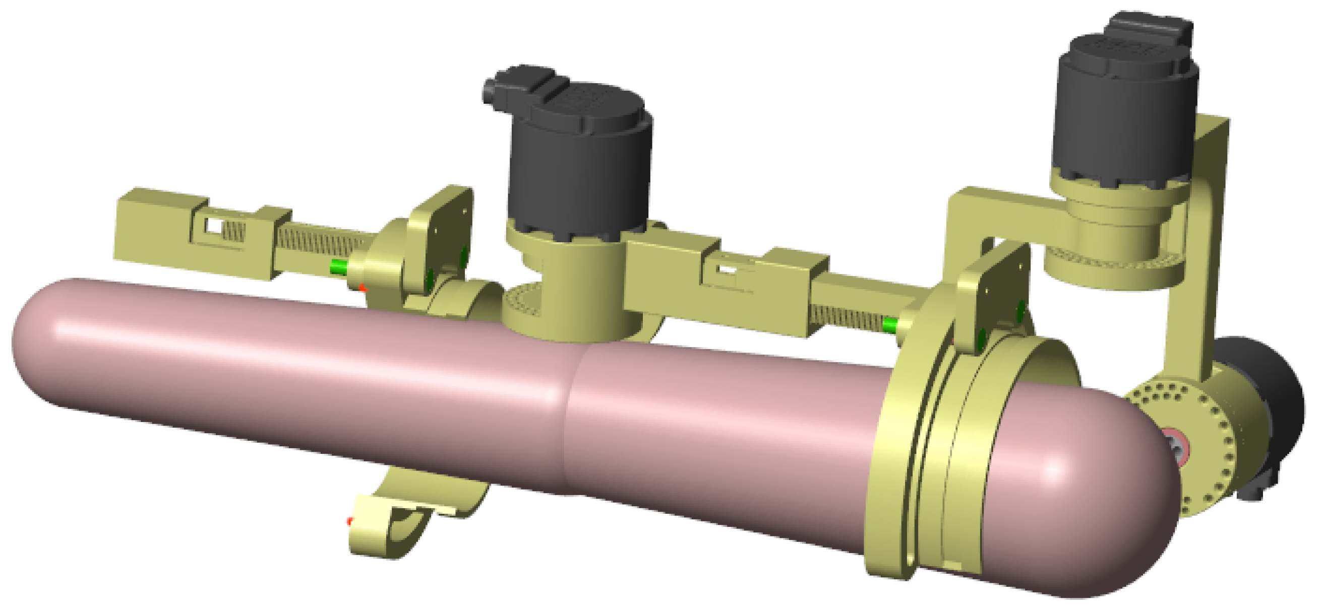
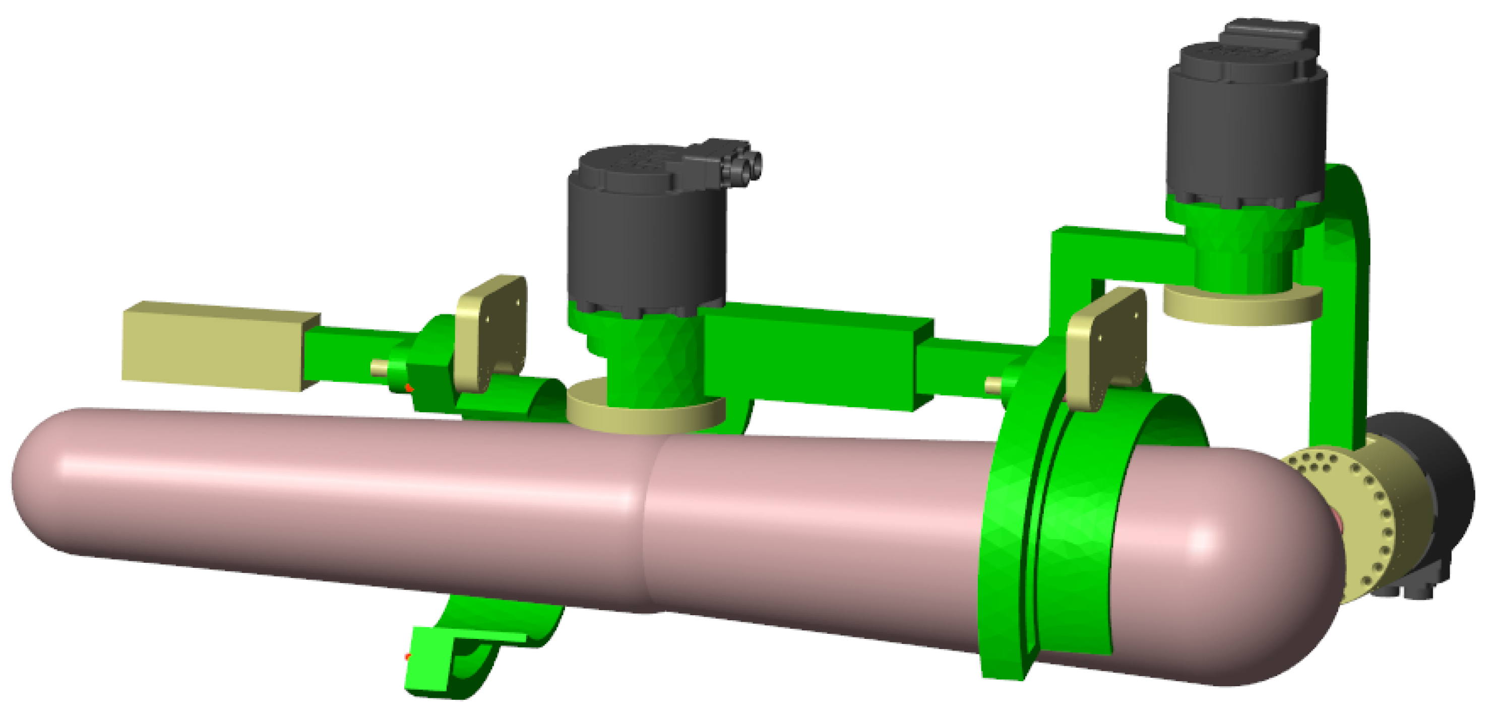
An alternative simulation was developed involving the elasticity of the main structural bodies (marked in green in Figure 10). Reduced Order Model (ROM) files were created for these parts based on imported .stp files, the defined material parameters, and boundary conditions. Then, the mesh was generated with the setting of an element size in the range of 0.1 mm ; 5 mm and geometrical simplifications typical for the finite element method regarding small faces with irregular edge geometries [36]. As a result, a ROM file with the matrix of the coordinate systems and their spatial orientation, the stiffness matrix, and the mass matrix was created.
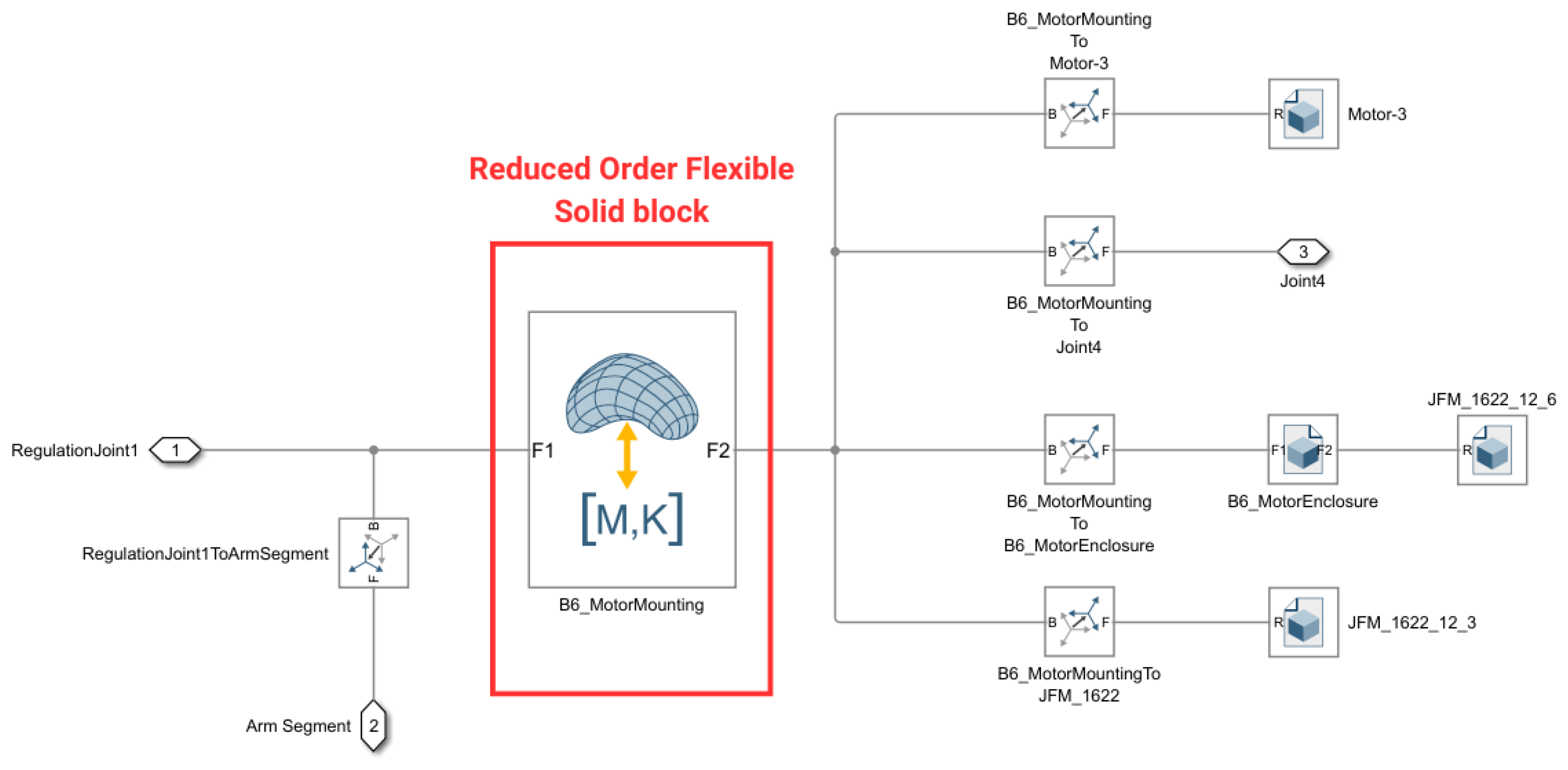
Compared to the original simulation, the selected File Solid blocks are replaced by the corresponding Reduced Order Flexible Solid blocks. An example of such a block in a submodel is visualized in Figure 11.
For the flexible bodies, sets of ordinary differential equations were solved using the ode15s solver [37,38].

3.7. Model Outputs

The exported outputs of the simulation system include
  • The required drive torques for all three active joints;
  • The reaction forces and torques at all five joints;
  • The reaction forces and torques at two points of attachment of the extremity;
  • The reaction forces and torques at two length adjustments.
One of the analysis’s objectives is to identify the maximum loads acting upon the exoskeleton components during task-oriented exercises. The selection process has been simplified, so instead of stresses and deformations, reaction forces and torques are considered. The analysis involves evaluating the reaction forces and torques at the joints of the subsequent mechanism parts. Identifying critical loading conditions is performed independently for each joint.
A critical loading set was defined as the set in which the reaction forces and torques simultaneously attained their maximum possible values regarding the L 2 norm. The selection process begins with calculating the absolute values of the forces and torques at the individual joints. These are then smoothed using a moving average method with a window of 0.5 s (effectively referring to 10 samples), which mitigates the effects of recording artifacts and simulation-induced peaks. The previously computed profiles are normalized in subsequent steps to the range [ 0 , 1 ] in a unitless space regarding the maximum force and torque value occurring at each point. This normalization aims to eliminate the units from the force and torque characteristics, facilitating further calculations.
The coefficient p C i ( t ) does not represent a physical quantity and is an aggregation operator [39] used only to numerically detect the moment of the extreme loads combined. It reflects that the criticality of the loads at the i-th characteristic point on the structure, and it is computed according to Formula (1), where F C i ( t ) stands for the normalized force and τ C i ( t ) stands for the normalized torque at this time. The searched configuration appears at the timestamp t when p C i ( t ) reaches its maximum value.
p C i ( t ) = F C i ( t ) · τ C i ( t )
The maximum p C i ( t ) coefficient is determined for each trajectory corresponding to male and female users, as the input trajectories are visibly gender-related.

4. Results and Discussion

4.1. The Required Actuating Torques

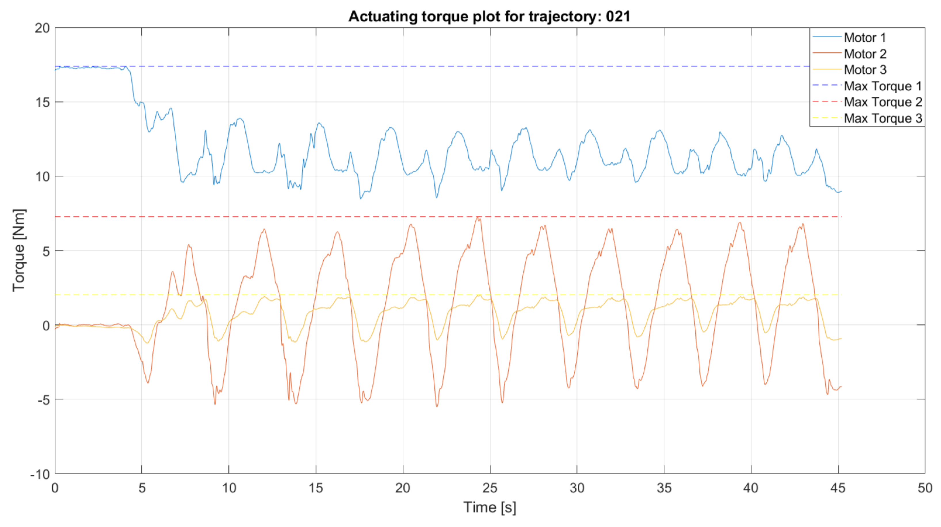
The actuating torques for the exoskeleton were computed based on multiple repetitions of the same exercise trajectories (see Figure 12). The torque trajectories were continuous and could have negative values, depending on the direction of the performed motion. Independent of the dimensions and mass of the model, simulations were performed on the sets of the trajectories recorded with male and female participants, as the use of particular degrees of freedom for the extremity varies depending on gender. Nevertheless, extreme values for the required motor torques were observed for the trajectories recorded for the male participants. Table 4 presents the results of selecting the maximum torque enabling the execution of all of the recorded ADLs. Therefore, motors with such torque parameters are applicable to lightweight rehabilitation exoskeletons with a similar construction for task-oriented treatment. In general, torques around 30 Nm can be treated as required to effectively abduct/adduct and flex/extend the shoulder, while a torque of around 10 Nm can be treated as required to effectively flex/extend the elbow.

4.2. Critical Reaction Loads

Table 5 presents the critical load set selected for all of the analyzed trajectories. Each row refers to the combination of loads potentially deforming the medial segment acting upon the selected load point. Moreover, the forces and torques of the presented values act simultaneously at at least one moment of the simulated exercises. The loads are highlighted in the active joints and passive joints (for each of the rollers) and at the attachment points of the extremity to the exoskeleton structure. The components of the reaction forces and torques are shown for each joint. Apart from the reactions at the extremity attachment points, the reaction torques along the Z-axis are zero because the other joints have mobility on those axes.
Active Joint 1 works under significant reaction forces along the X- and Y-axes. In contrast, Active Joint 2 exhibits forces of a similar magnitude in the opposite directions. On the contrary, Active Joint 3 is significantly less loaded compared to the previous two.
The passive joints, including Passive Joint 1 Roller 1, Passive Joint 1 Roller 2, Passive Joint 2 Roller 1, and Passive Joint 2 Roller 2, display a broad range of forces and torques. The forces on the X- and Y-axes vary from -250.20 N to 1058.88 N along the X-axis and from 22.89 N to 716.81 N along the Y-axis. Nevertheless, the strength of each roller must be capable of working under extreme loads, as their structure is the same.
The joint reactions will be further used for the strength analysis and the mass minimization performed as a continuation of this research. The Extremity Mounting 1 forces, on the other hand, will be used to select multiaxial force sensors to be placed between the main construction of the device and the elastic strap. These will be responsible for sensing the motion intentions of users during active treatment [40].

4.3. Deformability

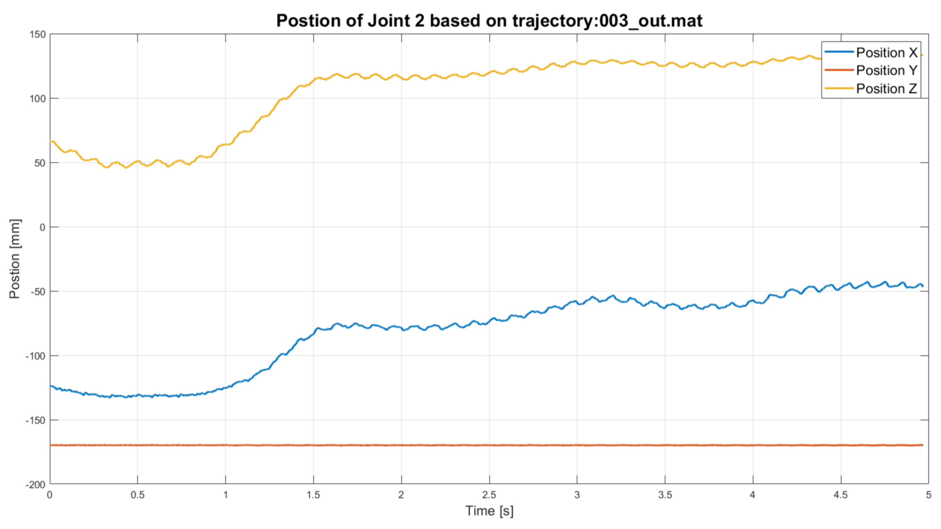
Compared to the rigid models, the deformability implemented into the model caused the positions of the characteristic points to oscillate. This was not only due to the deformations of the main components of the exoskeleton but also due to problems with position control over the model upon dynamically changing the inertial reactions from the distal parts of the device. An example of the resultant trajectory of a characteristic point is illustrated in Figure 13. Even though inaccuracies at the observed level are acceptable for biomechanical applications, these accumulate with the serial kinematic chain.
The results for extreme cases presented a temporary deviation between the intended gripping point and the performed gripping point of up to 15 cm. The value is significantly too high and can prevent ADL-based exercises from being performed, as it misses the key functionality. Nevertheless, the simulation results with deformable components suffer from accumulating inaccuracies coming from the significant impact of changing the inertial reactions in joint position control. The predicted inaccuracies were not observed in the real-life setup. Validation in Matlab Model Report resulted in the observation of 48 additional degrees of freedom caused by implementing six flexible bodies. Due to this, the total number of degrees of freedom of the system exceeded the number of constraints and position constraint equations, making the system redundant. The solver might have searched for different solutions within the following timestamps, which could have caused the observed oscillations. For this reason, the strength analysis was performed separately in the finite element environment as a structural static analysis with the substitute loads and constraints applied and then included in the kinematics analysis. The results of this strength analysis will be published as a separate paper.

5. Conclusions

Within the presented investigation, a multibody system for a rehabilitation exoskeleton of an upper extremity was built using rigid and deformable elements. Both of the models were used to compute the required driving torques and reactions at characteristic points while performing recorded ADLs. Thanks to this, a device capable of performing real-life task-oriented physiotherapy could be designed. The main conclusions of the investigation are the computed required driving torques, enabling task-oriented passive exercise using the exoskeleton, and the reaction loads appearing at the device’s joints.
In general, it can be assumed that driving a lightweight exoskeleton requires motors with a torque of around 30 Nm for the shoulder joint and around 10 Nm for the elbow joint. Due to the construction of the SmartEx-Home exoskeleton, internal/external rotations were not considered in these assumptions. For the requirements mentioned, it is possible to select lightweight drives with up to 1 kg of mass each [23].
The second part of the analysis was focused on the reaction forces and torques occurring at the device’s characteristic points. The designated values could be used further to perform a strength analysis or optimize the construction [41]. The values regarding the extremity attachment points could additionally be used to select multiaxial force sensors useful for active therapy.
Due to the relatively high oscillations in the deformable model identified in the presented environment, it was compared with the real-life device. These artifacts were not observed. Therefore, the strength analysis was separated from the multibody dynamics analysis in the Matlab/Simulink environment. This is the main limitation of the conducted study. Simultaneous iteration finite element method strength simulations will be repeated and used to analyze the kinematics of the system. This will be the subject of the continuation of this investigation. Due to the mentioned problems, it is not advised to include multiple flexible elements in simulated serial robots driven using joint position trajectories.
The developed simulation model will also be integrated with a module for automatic drive selection [23]. This would create a unified framework allowing for the automatic selection of drive sets based on the specified construction needs, without the need for the constructor’s intervention.
The presented methodology for building a multibody dynamics model could universally be used for similar lightweight exoskeletons based on trajectories gathered using IMU sensors or motion capture. Moreover, the numerical results of the presented investigation could be used to quickly validate similar designs for similar applications in terms of their strength without the need to perform a whole simulation. In terms of the presented design, these will be the basis for further strength validation and computational optimization of the SmartEx-Home exoskeleton’s construction to reduce its mass while meeting the strength and functional criteria.

6. Patents

The work described in this paper was used for the development of the design of an invention submitted to the protection of the Polish Patent Office under number P.452142.

Author Contributions

Conceptualization: P.F.; methodology: K.Z. and P.F.; software: K.Z.; validation: P.F.; formal analysis: K.Z. and P.F.; investigation: K.Z. and P.F.; resources: P.F.; data curation: K.Z.; writing—original draft preparation: K.Z. and P.F.; writing—review and editing: P.F.; visualization: K.Z.; supervision: P.F.; project administration: P.F.; funding acquisition: P.F. All authors have read and agreed to the published version of the manuscript.

Funding

This paper is based on the results of the “Development of a universal and lightweight construction of rehabilitation exoskeleton with a control algorithm dedicated to remote, home and task-oriented rehabilitation” SmartEx-Home project, financed in 2024-2026 (1,793,900 PLN), within the scope of scientific research and development works by the National Center for Research and Development (LIDER XIV, contract number LIDER14/0196/2023).

Institutional Review Board Statement

These experiments were carried out under the KB/132/2024 approval of the Bioethical Committee of the Medical University of Warsaw.

Informed Consent Statement

Informed consent was obtained from all of the subjects involved in this study.

Data Availability Statement

The medical data gathered for the simulations have not been made available. The remaining data can be shared upon request.

Conflicts of Interest

The authors declare no conflicts of interest.

References

  1. United Nations Department of Economic and Social Affairs. World Social Report: Leaving No One Behind in an Ageing World; United Nations: New York, NY, USA, 2023. [Google Scholar]
  2. de Meijer, C.; Wouterse, B.; Polder, J.; Koopmanschap, M. The effect of population aging on health expenditure growth: A critical review. Eur. J. Ageing 2013, 10, 353–361. [Google Scholar] [CrossRef]
  3. Kovner, C.T.; Mezey, M.; Harrington, C. Who cares for older adults? Workforce implications of an aging society. Health Aff. 2002, 21, 78–89. [Google Scholar] [CrossRef]
  4. World Health Organization; World Trade Organization. Promoting Access to Medical Technologies and Innovation: Intersections Between Public Health, Intellectual Property and Trade; World Health Organization and World Trade Organization: Geneva, Switzerland, 2020. [Google Scholar]
  5. Li, X.; You, K. Real-time tracking and detection of patient conditions in the intelligent m-Health monitoring system. Front. Public Health 2022, 10, 922718. [Google Scholar] [CrossRef]
  6. Payedimarri, A.B.; Ratti, M.; Rescinito, R.; Vanhaecht, K.; Panella, M. Effectiveness of Platform-Based Robot-Assisted Rehabilitation for Musculoskeletal or Neurologic Injuries: A Systematic Review. Bioengineering 2022, 9, 129. [Google Scholar] [CrossRef]
  7. Desmond, D.; Layton, N.; Bentley, J.; Boot, F.H.; Borg, J.; Dhungana, B.M.; Gallagher, P.; Gitlow, L.; Gowran, R.J.; Groce, N.; et al. Assistive technology and people: A position paper from the first global research, innovation and education on assistive technology (GREAT) summit. Disabil. Rehabil. Assist. Technol. 2018, 13, 437–444. [Google Scholar] [CrossRef] [PubMed]
  8. Olatunji, S.A.; Nguyen, V.; Cakmak, M.; Edsinger, A.; Kemp, C.C.; Rogers, W.A.; Mahajan, H.P. Immersive participatory design of assistive robots to support older adults. Ergonomics 2024, 67, 717–731. [Google Scholar] [CrossRef] [PubMed]
  9. Thøgersen, M.; Gull, M.A.; Kobbelgaard, F.V.; Mohammadi, M.; Bengtson, S.H.; Struijk, L.N.A. Exotic-a discreet user-based 5 dof upper-limb exoskeleton for individuals with tetraplegia. In Proceedings of the 2020 3rd International Conference on Mechatronics, Robotics and Automation (ICMRA), Shanghai, China, 16–18 October 2020; pp. 79–83. [Google Scholar]
  10. Huang, J.; Ji, J.R.; Liang, C.; Zhang, Y.Z.; Sun, H.C.; Yan, Y.H.; Xing, X.B. Effects of physical therapy-based rehabilitation on recovery of upper limb motor function after stroke in adults: A systematic review and meta-analysis of randomized controlled trials. Ann. Palliat. Med. 2022, 11, 521–531. [Google Scholar] [CrossRef] [PubMed]
  11. Eraifej, J.; Clark, W.; France, B.; Desando, S.; Moore, D. Effectiveness of upper limb functional electrical stimulation after stroke for the improvement of activities of daily living and motor function: A systematic review and meta-analysis. Syst. Rev. 2017, 6, 40. [Google Scholar] [CrossRef]
  12. Osiak, T.; Osiak, N.; Falkowksi, P.; Aktan, M.E.; Czerechowicz, P.; Ömürlü, V.E. Literature-based analysis of lower extremity kinematics and dynamics during task-oriented physiotherapy for rehabilitation robot design. In Lecture Notes in Networks and Systems; Springer: Berlin/Heidelberg, Germany, 2024. [Google Scholar]
  13. Falkowski, P.; Pikuliński, M.; Osiak, T.; Jeznach, K.; Zawalski, K.; Kołodziejski, P.; Zakręcki, A.; Oleksiuk, J.; Śliż, D.; Osiak, N. Similarity Analysis of Upper Extremity’s Trajectories in Activities of Daily Living for Use in an Intelligent Control System of a Rehabilitation Exoskeleton. Actuators 2025, 14, 324. [Google Scholar] [CrossRef]
  14. Alsubiheen, A.M.; Choi, W.; Yu, W.; Lee, H. The effect of task-oriented activities training on upper-limb function, daily activities, and quality of life in chronic stroke patients: A randomized controlled trial. Int. J. Environ. Res. Public Health 2022, 19, 14125. [Google Scholar] [CrossRef]
  15. Falkowski, P.; Rzymkowski, C.; Pilat, Z. Analysis of rehabilitation systems in regards to requirements towards remote home rehabilitation devices. J. Autom. Mob. Robot. Intell. Syst. 2023, 17, 61–73. [Google Scholar] [CrossRef]
  16. Falkowski, P.; Zawalski, K.; Oleksiuk, J.; Leczkowski, B.; Pilat, Z.; Aktan, M.E.; Akdogan, E.; Niedbalski, P.; Ömürlü, V.E.; Jarek, M.; et al. Systematic review of mechanical designs of rehabilitation exoskeletons for lower-extremity. Arch. Mech. Eng. 2024, 71, 621–644. [Google Scholar] [CrossRef]
  17. Fareh, R.; Elsabe, A.; Baziyad, M.; Kawser, T.; Brahmi, B.; Rahman, M.H. Will your next therapist be a robot?—A review of the advancements in robotic upper extremity rehabilitation. Sensors 2023, 23, 5054. [Google Scholar] [CrossRef]
  18. Coremans, M.; Carmeli, E.; De Bauw, I.; Essers, B.; Lemmens, R.; Verheyden, G. Error Enhancement for Upper Limb Rehabilitation in the Chronic Phase after Stroke: A 5-Day Pre-Post Intervention Study. Sensors 2024, 24, 471. [Google Scholar] [CrossRef]
  19. Borghi, B.; Aghamohammadi, N.R.; Cancrini, A.; Ramirez, A.; Celian, C.; Patton, J. Personalized robotic training on a planar reaching task. In Proceedings of the 2025 International Conference On Rehabilitation Robotics (ICORR), Chicago, IL, USA, 12–16 May 2025; pp. 1493–1499. [Google Scholar]
  20. Moulaei, K.; Bahaadinbeigy, K.; Haghdoostd, A.A.; Nezhad, M.S.; Sheikhtaheri, A. Overview of the role of robots in upper limb disabilities rehabilitation: A scoping review. Arch. Public Health 2023, 81, 84. [Google Scholar] [CrossRef]
  21. Hasan, S.K.; Bhujel, S.B.; Niemiec, G.S. Emerging trends in human upper extremity rehabilitation robot. Cogn. Robot. 2024, 4, 174–190. [Google Scholar] [CrossRef]
  22. Khalid, S.; Alnajjar, F.; Gochoo, M.; Renawi, A.; Shimoda, S. Robotic assistive and rehabilitation devices leading to motor recovery in upper limb: A systematic review. Disabil. Rehabil. Assist. Technol. 2023, 18, 658–672. [Google Scholar] [CrossRef]
  23. Falkowski, P.; Mohammadi, M.; Andreasen Struijk, L.N.; Rzymkowski, C.; Pilat, Z. Optimising a driving mechanism mechanical design of EXOTIC exoskeleton—A review on upper limb exoskeletons driving systems and a case study. Multibody Syst. Dyn. 2025, 1–24. [Google Scholar] [CrossRef]
  24. Calafiore, D.; Negrini, F.; Tottoli, N.; Ferraro, F.; Ozyemisci-Taskiran, O.; de Sire, A. Efficacy of robotic exoskeleton for gait rehabilitation in patients with subacute stroke: A systematic review. Eur. J. Phys. Rehabil. Med. 2022, 58, 1–8. [Google Scholar] [CrossRef] [PubMed]
  25. Rose, C.G.; Deshpande, A.D.; Carducci, J.; Brown, J.D. The road forward for upper-extremity rehabilitation robotics. Curr. Opin. Biomed. Eng. 2021, 19, 100291. [Google Scholar] [CrossRef]
  26. Kapsalyamov, A.; Hussain, S.; Jamwal, P.K. State-of-the-art assistive powered upper limb exoskeletons for elderly. IEEE Access 2020, 8, 178991–179001. [Google Scholar] [CrossRef]
  27. Siviy, C.; Baker, L.M.; Quinlivan, B.T.; Porciuncula, F.; Swaminathan, K.; Awad, L.N.; Walsh, C.J. Opportunities and challenges in the development of exoskeletons for locomotor assistance. Nat. Biomed. Eng. 2023, 7, 456–472. [Google Scholar] [CrossRef]
  28. Falkowski, P. A numerical algorithm for optimal selection of the driving mechanisms for ExoReha exoskeleton. In Proceedings of the 2024 10th International Conference on Mechatronics and Robotics Engineering (ICMRE), Milan, Italy, 27–29 February 2024; pp. 149–154. [Google Scholar]
  29. Firouzi, V.; Seyfarth, A.; Song, S.; von Stryk, O.; Ahmad Sharbafi, M. Biomechanical models in the lower-limb exoskeletons development: A review. J. NeuroEng. Rehabil. 2025, 22, 12. [Google Scholar] [CrossRef]
  30. Ren, B.; Liu, J.; Chen, J. Simulating human–machine coupled model for gait trajectory optimization of the lower limb exoskeleton system based on genetic algorithm. Int. J. Adv. Robot. Syst. 2020, 17, 1729881419893493. [Google Scholar] [CrossRef]
  31. Fregly, B.J. Design of Optimal Treatments for Neuromusculoskeletal Disorders using Patient-Specific Multibody Dynamic Models. Int. J. Comput. Vis. Biomech. 2009, 2, 145–155. [Google Scholar]
  32. Gedliczka, A.; Pochopień, P. Atlas Miar Człowieka: Dane do Projektowania i Oceny Ergonomicznej: Antropometria, Biomechanika, Przestrzeń Pracy, Wymiary Bezpieczeństwa; CIOP: Warsaw, Poland, 2001. [Google Scholar]
  33. Falkowski, P. Predicting dynamics of a rehabilitation exoskeleton with free degrees of freedom. In Proceedings of the Conference on Automation; Springer: Berlin/Heidelberg, Germany, 2022; pp. 223–232. [Google Scholar]
  34. McConville, J.T. Anthropometric Relationships of Body and Body Segment Moments of Inertia; Air Force Aerospace Medical Research Laboratory, Aerospace Medical Division: Dayton, OH, USA, 1981; Volume 32.
  35. Torzo, G.; Paolo, P. The real pendulum: Theory, simulation, experiment. Lat.-Am. J. Phys. Educ. 2009, 3, 221–228. [Google Scholar]
  36. Park, G.; Kim, C.; Lee, M.; Choi, C. Building geometry simplification for improving mesh quality of numerical analysis model. Appl. Sci. 2020, 10, 5425. [Google Scholar] [CrossRef]
  37. Rong, B.; Rui, X.; Tao, L.; Wang, G. Theoretical modeling and numerical solution methods for flexible multibody system dynamics. Nonlinear Dyn. 2019, 98, 1519–1553. [Google Scholar] [CrossRef]
  38. Vande Wouwer, A.; Saucez, P.; Vilas, C. Simulation of ODE/PDE Models with MATLAB®, OCTAVE and SCILAB. In Scientific and Engineering Applications; Springer International Publishing: Cham, Switzerland, 2014. [Google Scholar]
  39. Zahedi Khameneh, A.; Kilicman, A. Some construction methods of aggregation operators in decision-making problems: An overview. Symmetry 2020, 12, 694. [Google Scholar] [CrossRef]
  40. Falkowski, P.; Jeznach, K. Simulation of a control method for active kinesiotherapy with an upper extremity rehabilitation exoskeleton without force sensor. J. NeuroEng. Rehabil. 2024, 21, 22. [Google Scholar] [CrossRef] [PubMed]
  41. Falkowski, P. Light exoskeleton design with topology optimisation and fem simulations for fff technology. J. Autom. Mob. Robot. Intell. Syst. 2021, 15, 14–19. [Google Scholar] [CrossRef]
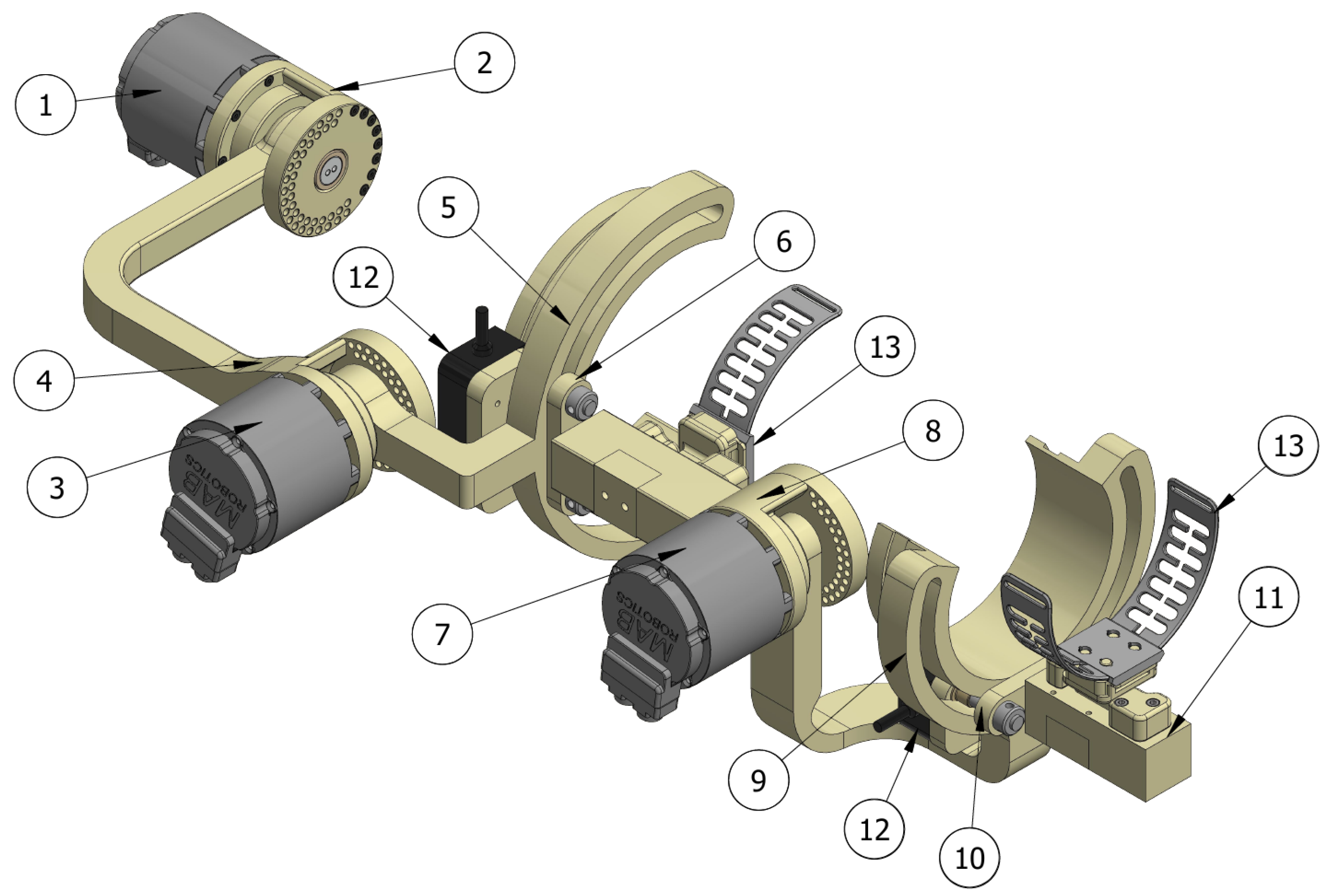
Figure 1. The exoskeleton structure with the main parts marked (labeled in Table 2).
Actuators 14 00426 g001
Figure 2. An example figure illustrating the measurement process.
Actuators 14 00426 g002
Figure 3. An example of the input trajectories used for the model.
Actuators 14 00426 g003
Figure 4. The application of a revolute joint between Body 1 and Body 2.
Actuators 14 00426 g004
Figure 5. A rigid version of a simulation model in its initial configuration.
Actuators 14 00426 g005
Figure 6. Construction of the Part 1 subsystem (connected to world frame-WF and joint 1).
Actuators 14 00426 g006
Figure 7. The application of a Prismatic Joint block to achieving an adjustment joint in the exoskeleton.
Actuators 14 00426 g007
Figure 8. The application of aWelded Joint block to attaching the extremity to the exoskeleton.
Actuators 14 00426 g008
Figure 9. A passive joint in the exoskeleton modeled as a pin curve slot mechanism.
Actuators 14 00426 g009
Figure 10. A deformable version of a simulation model in its initial configuration (deformable bodies marked in green).
Actuators 14 00426 g010
Figure 11. Construction of the Body 6 subsystem with a deformable part.
Actuators 14 00426 g011
Figure 12. An example plot of the actuating torque in driven joints for one of the ADLs.
Actuators 14 00426 g012
Figure 13. An example of the trajectory for Joint 2 center relative to the global reference frame for a fully deformable model.
Actuators 14 00426 g013
Table 1. Anatomical ranges of motion in exoskeleton joints—correlated with shoulder (1–3) and elbow (4–5).
JointAnatomical Range of Motion
1 0 ° 170 °
2 60 ° 180 °
3 70 ° 90 °
4 0 ° 145 °
5 77 85
Table 2. A list of the main exoskeleton components.
No.Part of the Exoskeleton
1Motor 1
2Body 1
3Motor 2
4Body 2
5Body 3/passive shoulder joint
6Body 4 with linear adjustment
7Motor 3
8Body 5
9Body 6
10Body 7 with linear adjustment
11Body 8
12Magnetic encoders
13Extremity mounting elastic straps
Table 3. Model part masses.
No.PartsMass [kg]
1Body 1 + Motor 11.18
2Body 2 + Motor 21.54
3Body 30.95
4Body 40.16
5Body 5 + Motor 31.42
6Body 61.08
7Body 70.13
8Body 80.14
9Arm3.15
10Forearm + hand2.1
Table 4. Maximum possible torque values for each motor regarding all simulated trajectories.
MotorMax. Torque [Nm]
129.44
230.83
39.94
Table 5. The selected critical set of reaction loads (AJ—active joint; PJ—passive joint; EM—extremity mount; Z—axis of joint rotation or an axis perpendicular to the attachment surface).
Load PointConstraint Force [N]Constraint Torque [Nm]
X Y Z X Y Z
AJ 1−500.18−472.41−329.70−243.31160.210.00
AJ 2345.29475.38−516.26−94.39−143.730.00
AJ 379.8632.57−7.55−2.15−4.320.00
PJ 1 Roller 11058.88−369.57−68.79−71.51−64.220.00
PJ 1 Roller 2−250.20716.81−68.44−67.26−61.570.00
PJ 2 Roller 1−52.8822.89−3.90−0.231.450.00
PJ 2 Roller 2−23.9555.32−30.15−0.721.220.00
EM 130.856.6817.64−0.363.030.04
EM 257.25−4.0922.88−2.541.644.62
Disclaimer/Publisher’s Note: The statements, opinions and data contained in all publications are solely those of the individual author(s) and contributor(s) and not of MDPI and/or the editor(s). MDPI and/or the editor(s) disclaim responsibility for any injury to people or property resulting from any ideas, methods, instructions or products referred to in the content.