1. Introduction
Low-speed, high-torque actuators are essential in industries like mining, metallurgy, and shipbuilding, with a prime example being the drive motor for scraper conveyors in mines [
1]. Permanent magnet synchronous motors (PMSMs) are frequently used in these applications because of their compact design, high load-bearing capacity, simple structure, and reliable performance [
2].
For tasks like large astronomical telescopes, radar systems, and robotic joints, PMSMs are often paired with traditional transmission methods, such as worm gears or gearboxes. However, as the size of the application grows, either the motor diameter must increase, or multiple motors need to be synchronized. Larger motor diameters complicate manufacturing, while coordinating multiple motors adds complexity to control systems [
3].
An alternative is the permanent magnet arc motor (PMAM), which uses a segmented structure with multiple stator units. This design offers high-precision positioning and significant torque, enabling direct drives for large telescopes, radar systems, and tank gun control mechanisms [
4]. While Proportional–Integral (PI) control is commonly used for PMSMs, it struggles to maintain high performance in the presence of nonlinearities, uncertainties, and disturbances [
5]. Moreover, the segmented stator structure in PMAMs can lead to magnetic permeability variations and phase imbalances, causing periodic torque pulsations [
6]. To address these issues, advanced control strategies like model predictive control [
7,
8], active disturbance rejection control [
9,
10,
11], adaptive control [
12,
13], and sliding mode control (SMC) have been developed to enhance performance and stability.
SMC has been extensively studied for enhancing the disturbance rejection and robustness of permanent magnet (PM) motor systems [
14]. The key advantage of SMC lies in its ability to drive the system’s state towards a predefined sliding surface, where the system exhibits robustness against disturbances, parameter variations, and model uncertainties. This characteristic is highly desirable in motor control applications, especially when dealing with unpredictable external forces or mechanical imperfections.
However, traditional SMC, which typically employs linear sliding surfaces, faces several limitations when applied to complex systems such as PM motors [
15]. One major drawback is its reliance on asymptotic convergence, meaning the system state only reaches the desired equilibrium after an infinite amount of time. While this ensures stability, the convergence speed is often too slow for applications that require fast and precise responses, such as high-speed or high-performance motor systems.
The integral sliding surface, which removes the need for the reaching phase, provides excellent robustness, making it well-suited for precise control applications. However, it may face challenges such as integral saturation, leading to increased overshoot [
16]. In contrast, the terminal sliding surface facilitates rapid convergence of the system state in finite time, ensuring robust performance and high control precision, all while maintaining a smooth control process and avoiding chattering [
17]. The application of fractional-order integral sliding surfaces, based on fractional-order calculus principles, has been explored in permanent magnet synchronous motors. This approach reduces the influence of past errors and increases sensitivity to current errors, thus effectively mitigating integral saturation [
18]. In [
19], a higher-order, non-singular terminal sliding surface was introduced, incorporating multiple terminal terms to establish a connection between the sliding surface and feedback currents. This innovation enabled the combined control of motor position, speed, and current, significantly enhancing both the system’s robustness and its steady-state and dynamic performance. To overcome large overshoot and chattering, ref. [
20] developed a novel non-singular terminal sliding surface with an integral terminal factor, resulting in improved dynamic response.
In [
21], a super-twisting integral terminal sliding mode control (TSMC) is introduced for controlling the speed of a synchronous motor, integrating an extreme learning machine to enhance performance. Similarly, in [
22], a novel SMC based on the homogeneous property is proposed for servo systems, demonstrating finite-time convergence irrespective of initial conditions. In this approach, the speed error is chosen as the sliding mode surface to avoid issues related to the singularity of its derivative. However, achieving simultaneous convergence of both the speed error and its derivative remains a challenge, potentially leading to speed overshoot, as discussed in [
23].
Traditional sliding mode control often faces the issue of chattering, where the control signal fluctuates rapidly between different values. This oscillation can cause unwanted vibrations and even lead to mechanical degradation in motor components. As such, chattering severely limits the practical implementation of traditional SMC in real-world applications, particularly where smooth and precise operation is essential.
To address this, a terminal switching gain term is incorporated into the traditional exponential reaching law, and the switching function is replaced with a saturation function, as proposed in [
24]. This modification significantly enhances robustness against system uncertainties. Adaptive switching gain adjustments using power and exponential functions are explored in [
25,
26,
27], respectively. Additionally, an innovative adaptive law for switching gains is presented for both slow and fast subsystems in flexible joint robots (FJRs), eliminating the need for prior knowledge of disturbance bounds and ensuring asymptotic convergence to zero [
28]. Furthermore, a practical adaptive FTSMC is developed for enhanced tracking performance in servo motor systems, utilizing a state observer and a bidirectional adaptive law [
29]. Professor Andrey Polyakov proposed a fixed-time sliding mode algorithm [
30]. It has been used in the control of robotic systems, allowing for adjusting a guaranteed convergence time of system trajectories into a prespecified neighborhood of the origin independently of initial conditions [
31,
32,
33].
In this paper, a fast TSMC based on a novel variable exponent sliding surface for PMAM is proposed. The contribution lies in the introduction of a new fast-converging sliding surface that can converge to the origin in finite time, regardless of the initial state. Additionally, this sliding surface possesses robustness similar to that of an integral sliding surface, meaning it can help the state variables converge to the origin even if they are not on the sliding surface. The paper also adopts a fast terminal reaching law, which combines terminal attraction factors and linear convergence terms to achieve global fast convergence of the reaching law. A strict Lyapunov stability proof is provided, and the theoretical proof demonstrates the ability of the terminal attraction factor and linear convergence terms in disturbance rejection.
The remainder of this paper is organized as follows:
Section 2 introduces the mathematical model of PMAM.
Section 3 details the design of the fast FTSMC based on a novel variable exponent sliding surface.
Section 4 verifies the efficacy of the proposed control approach through experiments, and
Section 5 concludes this paper.
2. Mathematical Model of PMAM
The stator winding is considered to be a balanced three-phase configuration, with the impacts of magnetic saturation, eddy currents, and hysteresis losses disregarded. By applying the field-oriented control strategy and accounting for lumped disturbances, the mathematical representation of the PMAM in the d-q axis synchronous reference frame is formulated as
where
J is the moment of inertia,
is the mechanical velocity,
is the number of pole pairs,
is the flux linkage,
is the viscous coefficient,
is the speed-loop lumped disturbance,
is bounded by
, where
D is the upper bound of
, and
id,
iq,
ud,
uq,
Ld, and
Lq are d-axis current, q-axis current, d-axis voltage, q-axis voltage, d-axis inductance, and q-axis inductance, respectively.
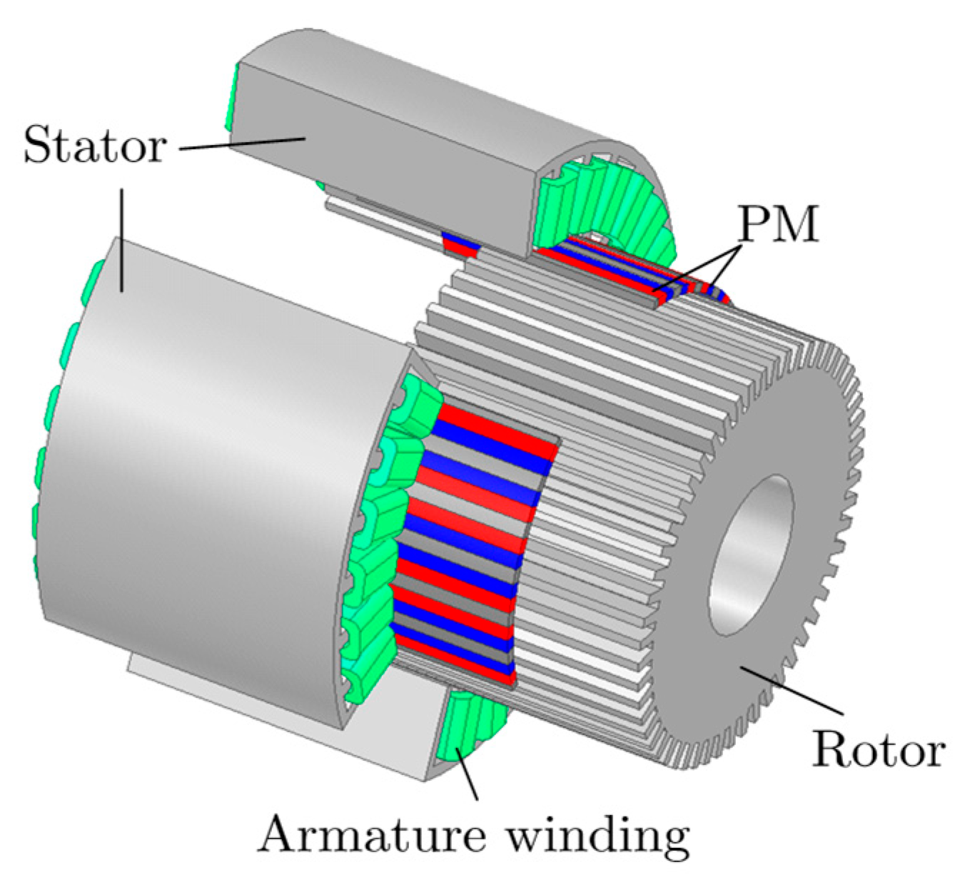
PMAM is derived from the permanent magnet (PM) rotating motor. It begins by slicing the rotating motor radially, transforming the stator and rotor into the primary and secondary structures of a flat linear motor. These structures are then bent at a specific angle to create the PM arc motor, as shown in
Figure 1.
The operational principle of the PMAM resembles that of a switched reluctance motor. The magnetic field generated by the PMs modifies the reluctance of the air gap, interacting with the armature windings. The rotor core operates on the principle of minimum reluctance, ensuring that magnetic flux follows the path of least reluctance and aligns with the magnetic field axis.
The PMAM features an arc-shaped rotor and stator design, optimizing magnetic flux utilization, while the PMSM employs a cylindrical rotor configuration that can result in larger dimensions for high-torque applications. In contrast, the axial-flux PMSM utilizes a disk-shaped configuration, allowing for a shorter axial length and a higher torque-to-weight ratio. Regarding cooling, the PMAM design facilitates effective heat dissipation through its exposed surfaces, whereas the PMSM may require additional cooling methods. The axial-flux PMSM benefits from improved cooling characteristics due to its flat geometry, which allows for better airflow or liquid cooling options. In terms of performance, the PMAM offers high-torque capabilities and efficiency due to its optimized design. The conventional PMSM is generally efficient but may face limitations related to geometry and thermal management. On the other hand, the axial-flux PMSM is recognized for its high power density and efficiency, often outpacing traditional designs. Overall, each motor type has its unique advantages, making them suitable for different applications based on performance requirements and design constraints. The comparison of PMAM, PMSM, and axial-flux PMSM is listed in
Table 1.
PMAMs are affected by main disturbances such as end torque, cogging torque, and magnetic flux harmonics. The segmented stator structure, typical in PMAMs, creates interruptions in the magnetic circuit continuity, causing local fluctuations in the flux density. These fluctuations lead to the generation of end torque components, which can be described as
where
,
,
, and
are rotor position,
n-order harmonic component of end torque, polar pitch, and phase difference in the forces on both sides, respectively.
The presence of tooth gaps alters the distribution of the magnetic field within the air gap, subsequently affecting the magnetic permeability of the air gap and leading to torque fluctuations. The cogging torque can be represented as
where
represents the
nth-order harmonic component of cogging torque, and
N is the least common multiple between stator slots and poles.
The torque, considering flux harmonics, can be written as
where
is the fundamental component, and
is the 6th-order harmonic component of the torque caused by flux harmonics.
3. Design of the New Control Strategy
Lemma 1 ([
34])
. For system , where x is the system state, and y is known, if there exists a continuously differentiable positive definite radially unbounded function such thatwhere , , , and , then the system will converge to the origin in a fixed time. The neighborhood and the settling time satisfy 3.1. Problem of Conventional SMC
Sliding mode control offers advantages such as insensitivity to disturbances and parameters, as well as fast response speed. The design of sliding mode control involves two processes: the approaching mode and the sliding mode. Correspondingly, the design of sliding mode control must satisfy the reachability condition of the sliding surface, which means that any point of motion outside the sliding surface will reach the surface within a finite time. On the other hand, it is also necessary to ensure the stability of the sliding motion, which guarantees that the system state can slide along the sliding surface and eventually converge to the origin.
The motion equation of PMAM can be rewritten as
where
d is the lumped disturbance including viscous torque. The viscous torque can be included in the lumped disturbance to be suppressed by the proposed controller.
d is bounded by
, where
is a known positive constant.
The constant reaching law can be written as
where
s is the sliding surface to be designed, and
is the constant speed approach coefficient,
, which ensures that
s approaches zero while maintaining the same gain.
The sliding surface is typically designed as
where
is the reference velocity, and
c is the positive constant.
By deriving the sliding surface
s above and integrating it with the rotor motion equation, one can have
Then, the designed control input can be simplified as
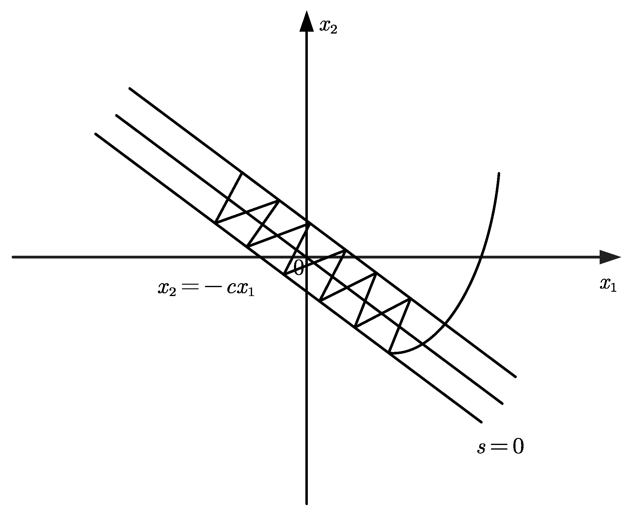
Figure 2 shows the two motion phases of traditional sliding mode control. Although the traditional design scheme of SMC has strong robustness, it has two significant drawbacks. On the one hand, in order to fully suppress external disturbances and ensure system stability, the value of
needs to be large, which results in considerable chattering in the control system even when the current external disturbances are small. On the other hand, the linear sliding surface can only guarantee the asymptotic convergence of the state variables, with a slow convergence rate, making it difficult to ensure fast performance. Specifically, when s
s converges to 0, one can have
Solving the differential equation yields
It can be observed that asymptotically converges to the origin.
3.2. Proposed Terminal Sliding Mode Control Based on Fixed-Time Sliding Surface
To mitigate the impact of chattering induced by the switching function on control performance, the introduction of a terminal attraction factor and a linear term allows for adaptive adjustment of the convergence rate based on the error magnitude. The newly designed global fast convergence approach can be expressed as
where
,
, and
are the positive constants of the reaching law.
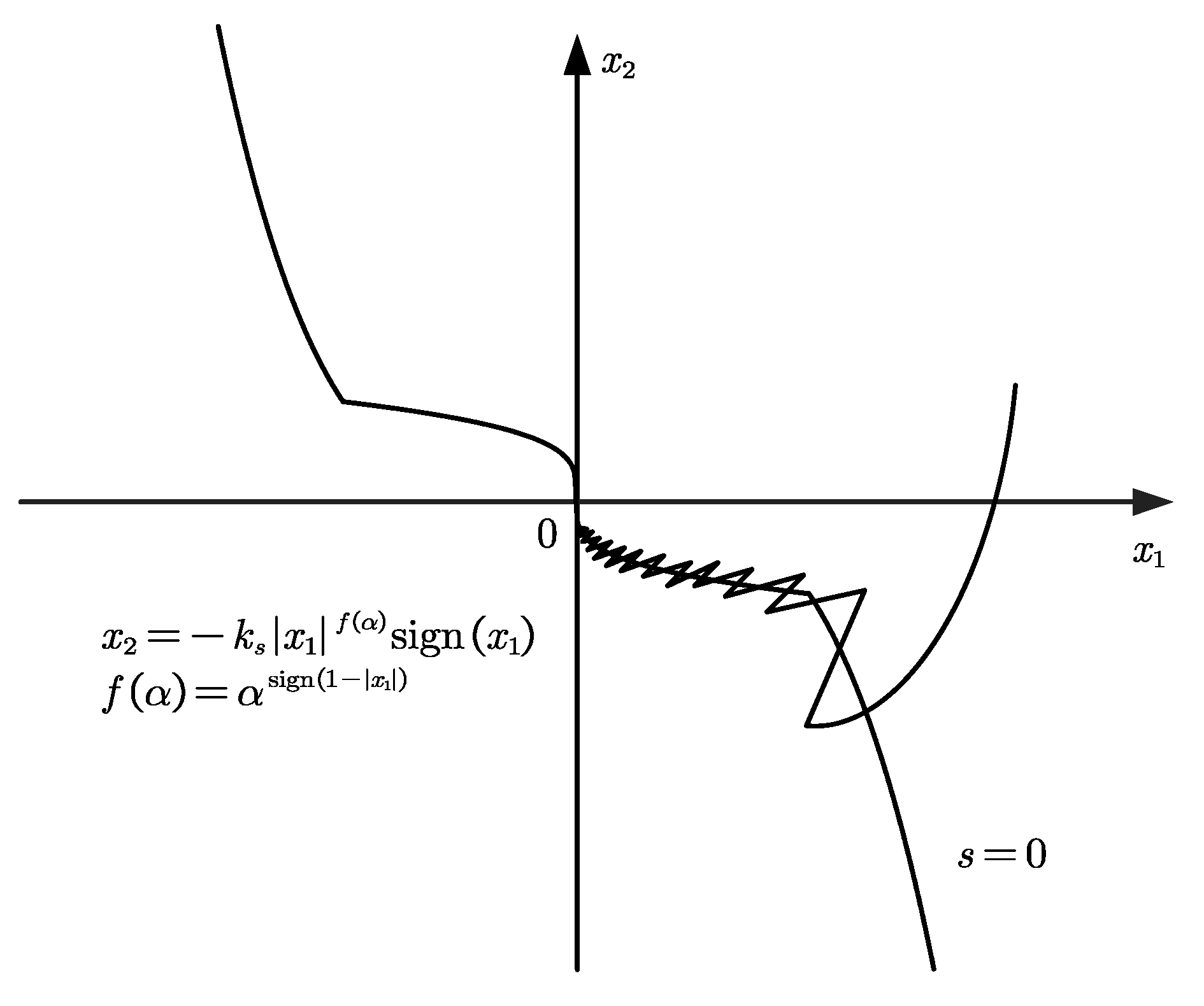
To improve the asymptotic convergence characteristics of the linear sliding mode surface, a novel fixed-time converging sliding mode surface is proposed. The key feature of this sliding mode surface lies in its robustness; even if s
s does not converge to zero,
x1 and
x2 can still converge to the vicinity of the origin under the influence of the designed sliding mode surface. Another important characteristic is that it maintains a consistently fast convergence rate throughout the entire convergence process in an adaptive manner. Moreover, the fixed convergence time for
x1 and
x2 is independent of the initial conditions. The proposed fixed-time sliding mode surface is written as
where
,
is a known positive constant,
is the positive constant of the sliding mode surface, and
is the variable exponent function.
Figure 3 shows the two motion phases of the proposed sliding mode control.
The parameters include the reaching law and the sliding surface. The reaching law, denoted by Equation (15), enhances robustness by quickly bringing the system state back to the sliding surface. To ensure the system’s disturbance tolerance and stability, the sum of , , and must be greater than the upper bound of the system disturbance . Increasing , , and accelerates the reaching process, stabilizing the state near the sliding surface. However, excessive values of and can cause overshoot and significant chattering near the surface. Excessive values of will lead to chattering. Therefore, it is recommended to gradually increase , , and while keeping relatively small, ensuring that stability is maintained.
After reaching the sliding surface, the system state converges to the equilibrium point along the surface. The larger the values of and α, the stronger the disturbance rejection capability and the faster the convergence rates of x1 and x2. However, this also makes it more likely to cause overshooting. Therefore, the sliding surface parameters should balance convergence speed and overshoot.
The designed sliding mode surface satisfies
This ensures that the convergence speed of the designed sliding mode surface is always superior to , , , and .
To further analyze the advantages of the proposed sliding mode surface as guided by [
32,
33], we theoretically examined its superiority. When the system moves onto the sliding mode surface,
x1 and
x2 will move along the sliding mode surface, and one can have
,
,
,
, and
; then, the sliding speed on the sliding mode surface will depend on
x2. According to Equation (17), one can have
and
Then, according to Equations (18) and (19), it can be theoretically proven that the superiority of the proposed sliding mode surface holds true, whether x1 is greater than 1 or less than 1, as the proposed sliding mode surface exhibits a faster convergence rate in both cases.
By deriving the proposed sliding surface
s above and integrating it with the rotor motion equation, one can have
Then, the proposed designed control input can be simplified as
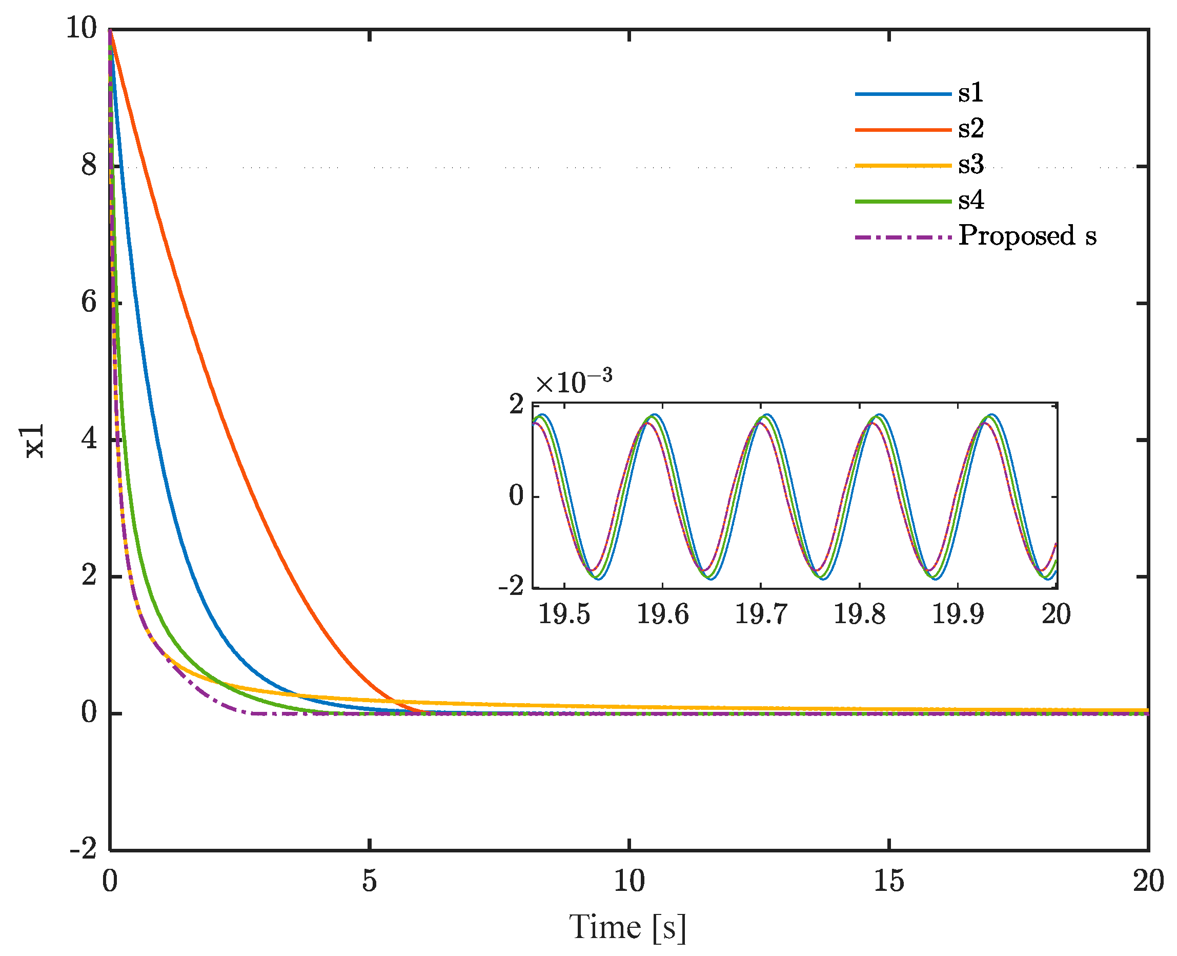
Figure 3 shows the convergence performance of different sliding mode surfaces. The initial value of
under the five different sliding mode surfaces is set to 10. A sinusoidal disturbance with an amplitude of 0.1 and a frequency of 55 rad/s is applied to all sliding surfaces.
is set to 0.5, and
is set to 1. As shown in
Figure 4, both the convergence speed and disturbance rejection ability of the proposed sliding surface are superior to the other four sliding surfaces.
3.3. Stability Analysis
To verify the stability of the proposed SMC system, we introduce the general Lyapunov function:
Differentiating
V(
t), one can have
If
, then one can have
If
, where
, then
is defined as an arbitrarily small positive constant, and one can have
Then, will converge to the set {V ≤ 1} in a finite time , where denotes positive constants. In this case, the impact of on the convergence speed is much greater than that of and .
If
, then one can have
According to the proof in [
34],
s will stabilize in region
in finite time
, where
denotes positive constants.
Here, is a small positive number.
After s converges to the region
, one can have
Without loss of generality, let
, where
is in the region
. By setting
and according to Equation (27), one can obtain
. To demonstrate the stability of the sliding surface, we introduce a new Lyapunov function:
The derivative of
V2 can be written as
Then, considering the inequality in Equation (17),
can be rewritten as
According to Lemma 1,
will converge to a small region
bounded by
The settling time
satisfies
In conclusion, the stability of the proposed SMC has been proven.
4. Experimental Results
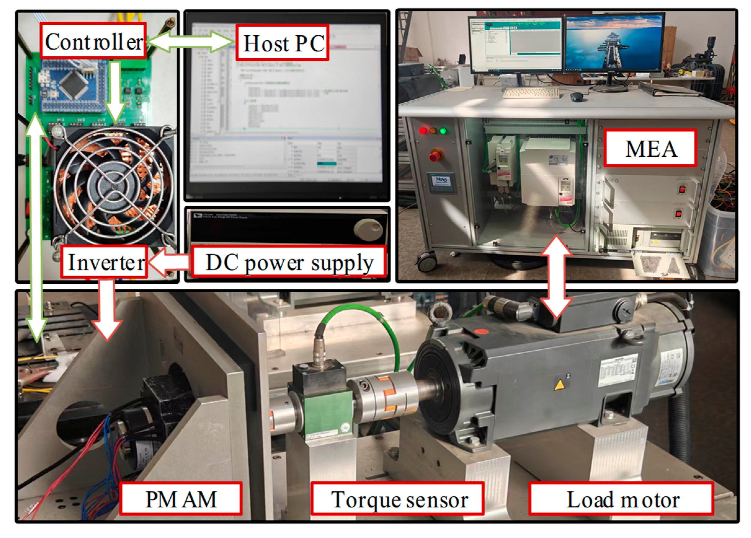
In this section, an experimental platform is established, and a surface-mounted PMAM is chosen as a prototype for control experiments to validate the effectiveness of the proposed algorithm. The experimental platform is depicted in
Figure 5, while the PMAM data are summarized in
Table 2. The inductance and resistance of the motor model are measured using an LCR meter. Flux linkage is identified through no-load back EMF measurement. The motor’s moment of inertia and viscous damping coefficient are tested using the method described in [
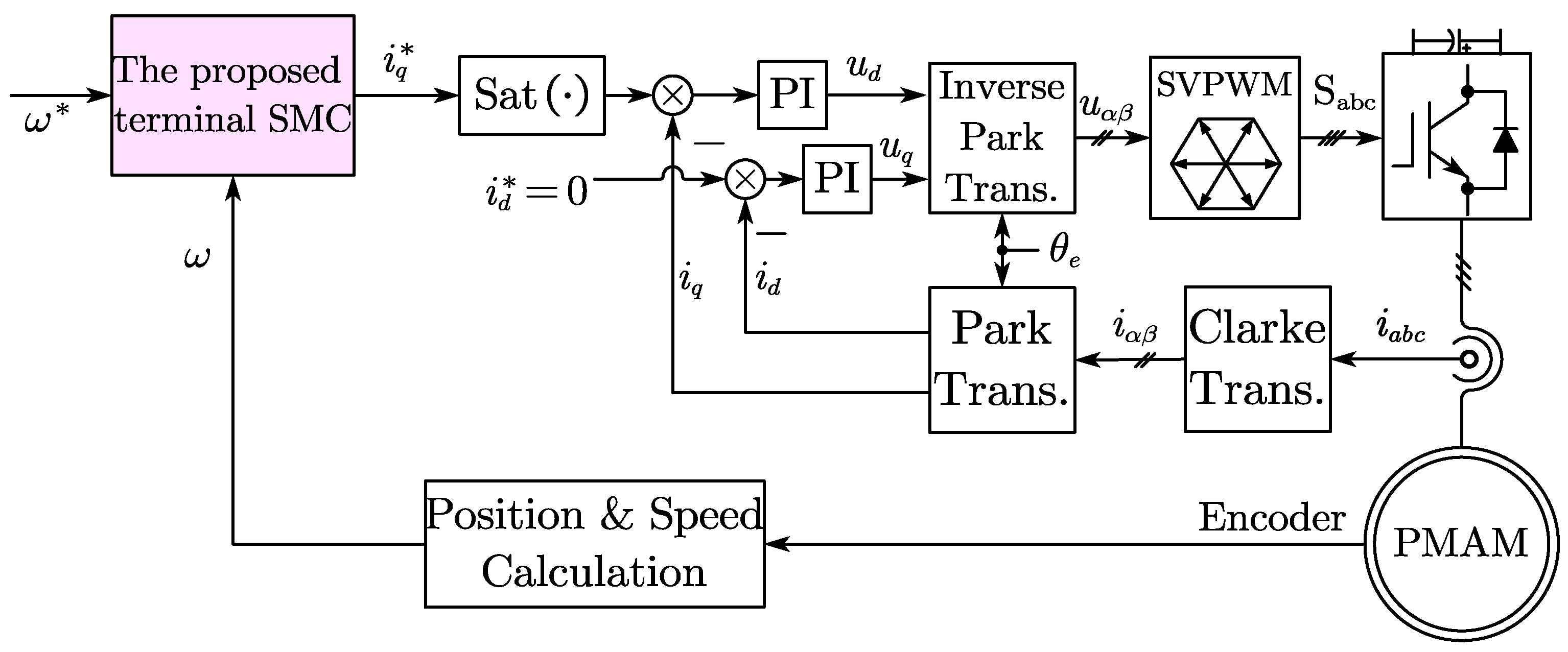
35]. A diagram illustrating the proposed strategy is provided in
Figure 6.
The motor’s drive system is designed, and the control algorithm is implemented using STM32 code. The program is written in the C language and developed with the Keil software (Keil uVision5). The circuit design in this article primarily utilizes an Intelligent Power Module (IPM), with Mitsubishi Electric’s PSS15S92F6 module employed as the three-phase inverter. For control, the STM32F407VET chip, based on ARM’s Cortex-M4 processor core, was used.
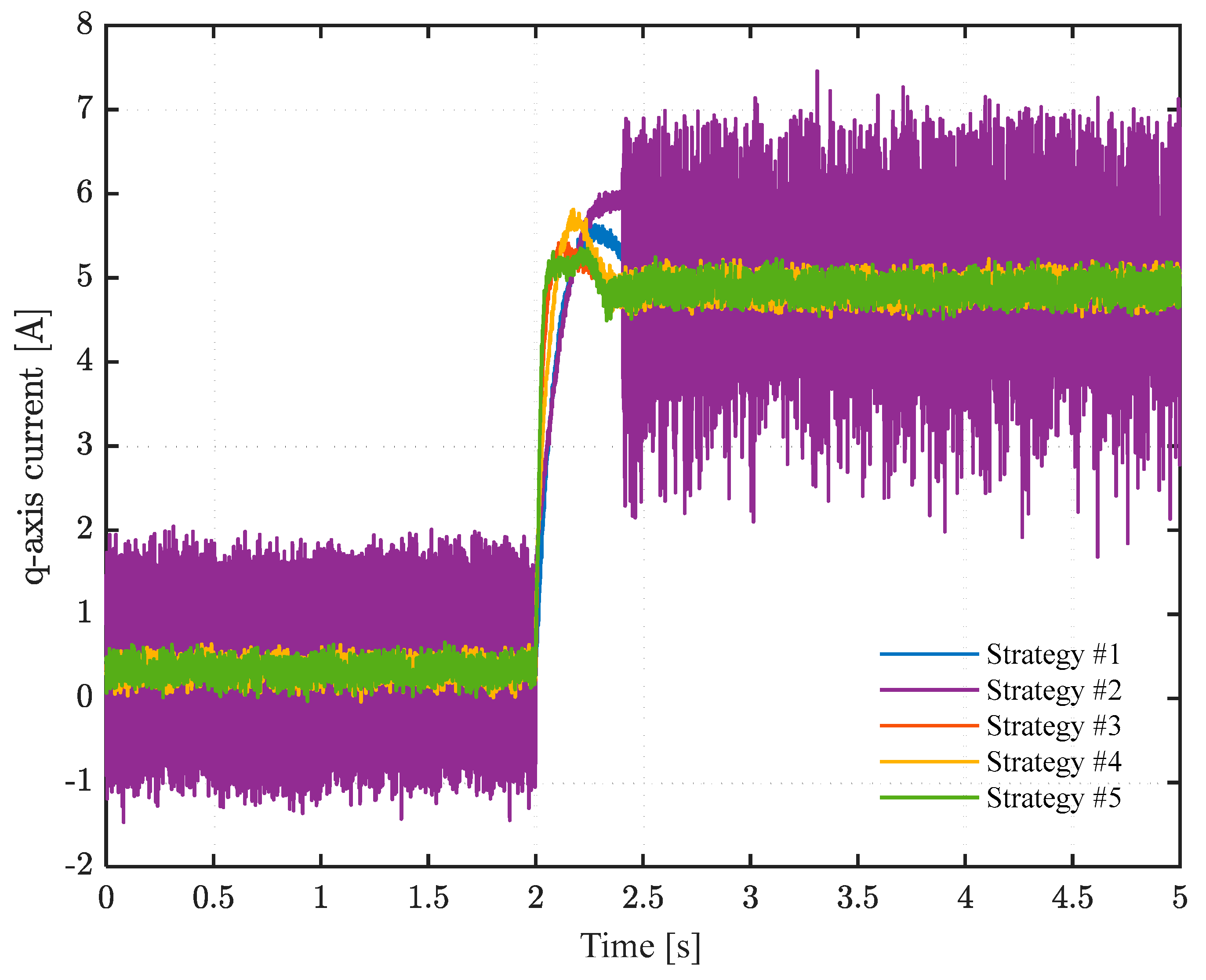
To validate the effectiveness of the proposed terminal sliding mode control (SMC) based on a fixed-time sliding surface, traditional PI control tagged with strategy #1, conventional SMC is tagged with strategy #2, TSMC based on linear sliding surface
s1 tagged with strategy #3, TSMC based on terminal sliding surface
s2 tagged with strategy #4, and the proposed TSMC based on fixed-time sliding surface tagged with strategy #5 are all used in different experimental cases. The parameters of the four strategies are listed in
Table 3, where the ‘#’ denotes the number notation.
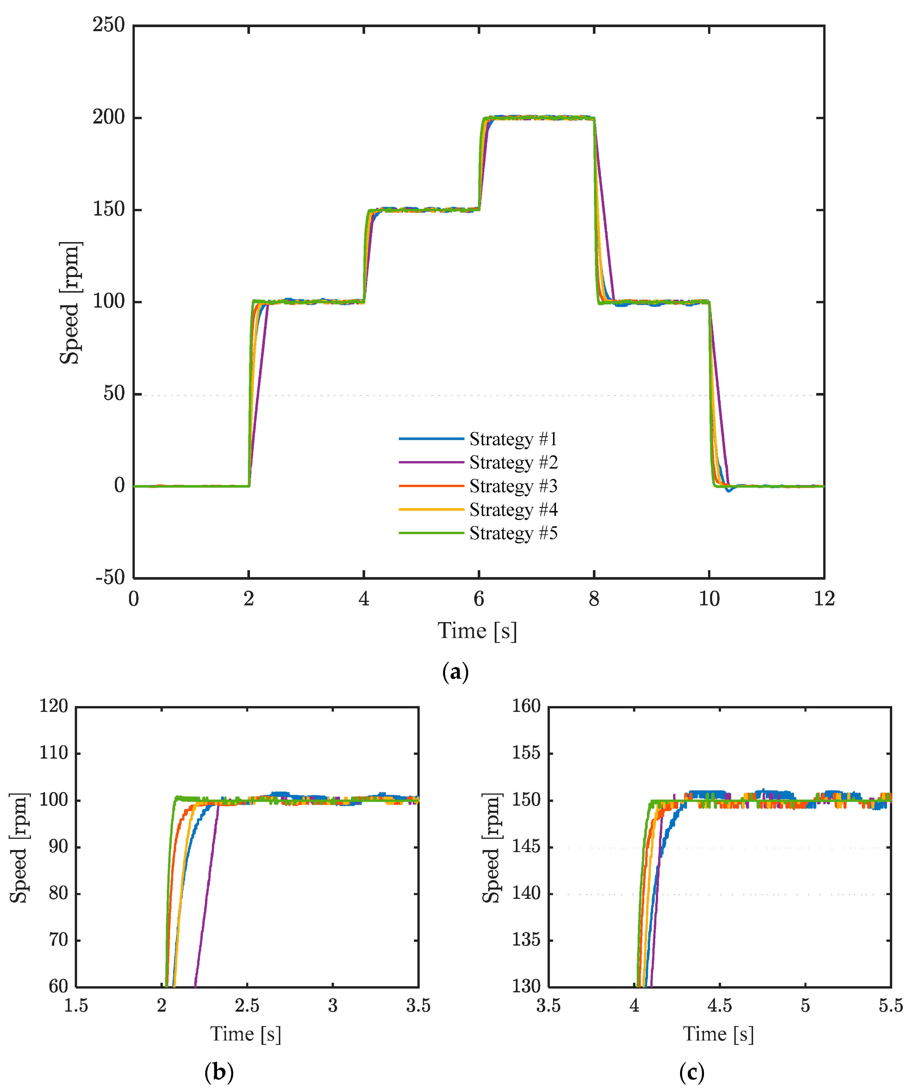
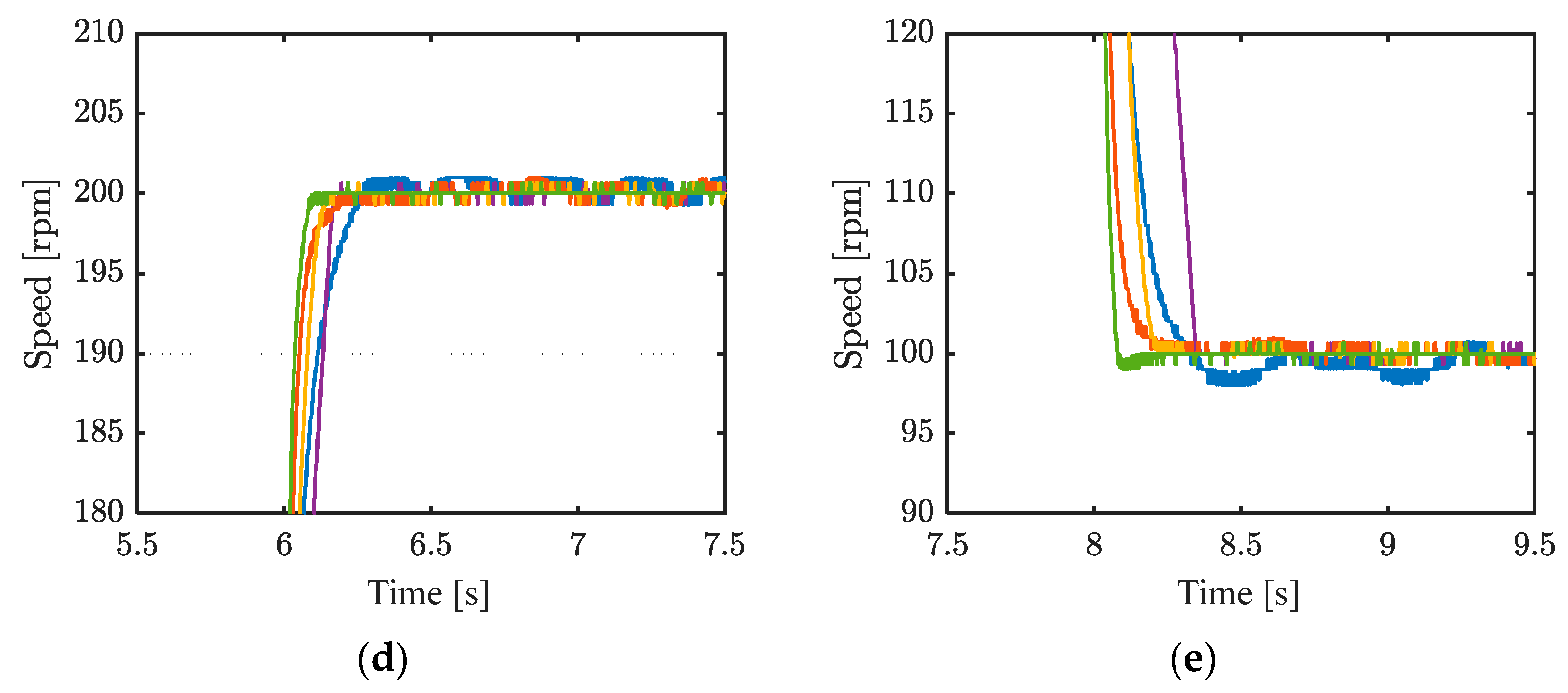
Figure 7 shows the speed response and local enlarged views. Starting from 2 s, the reference speed is set to 100 rpm, 150 rpm at 4 s, 200 rpm at 6 s, 100 rpm at 8 s, and 0 rpm at 10 s.
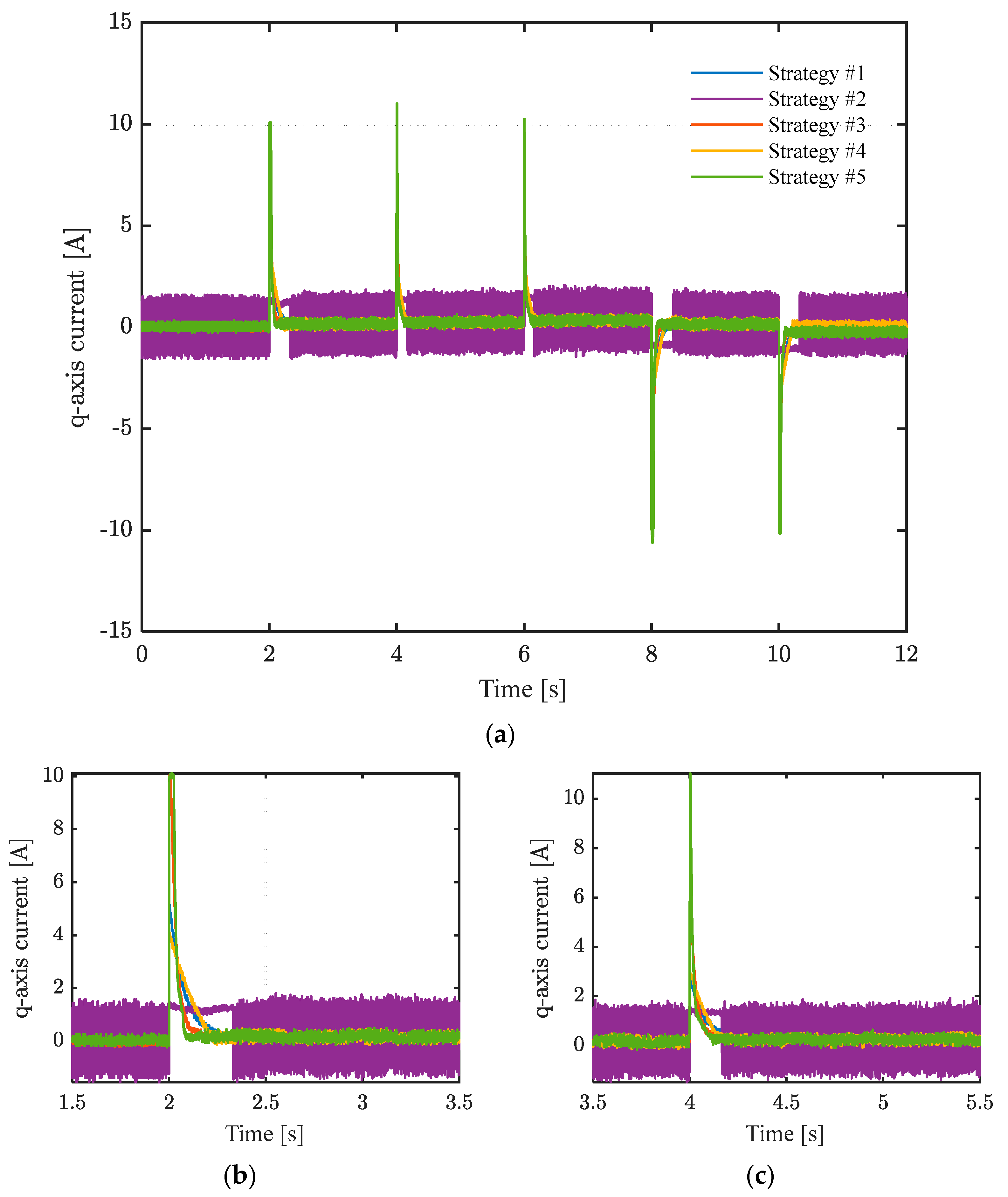
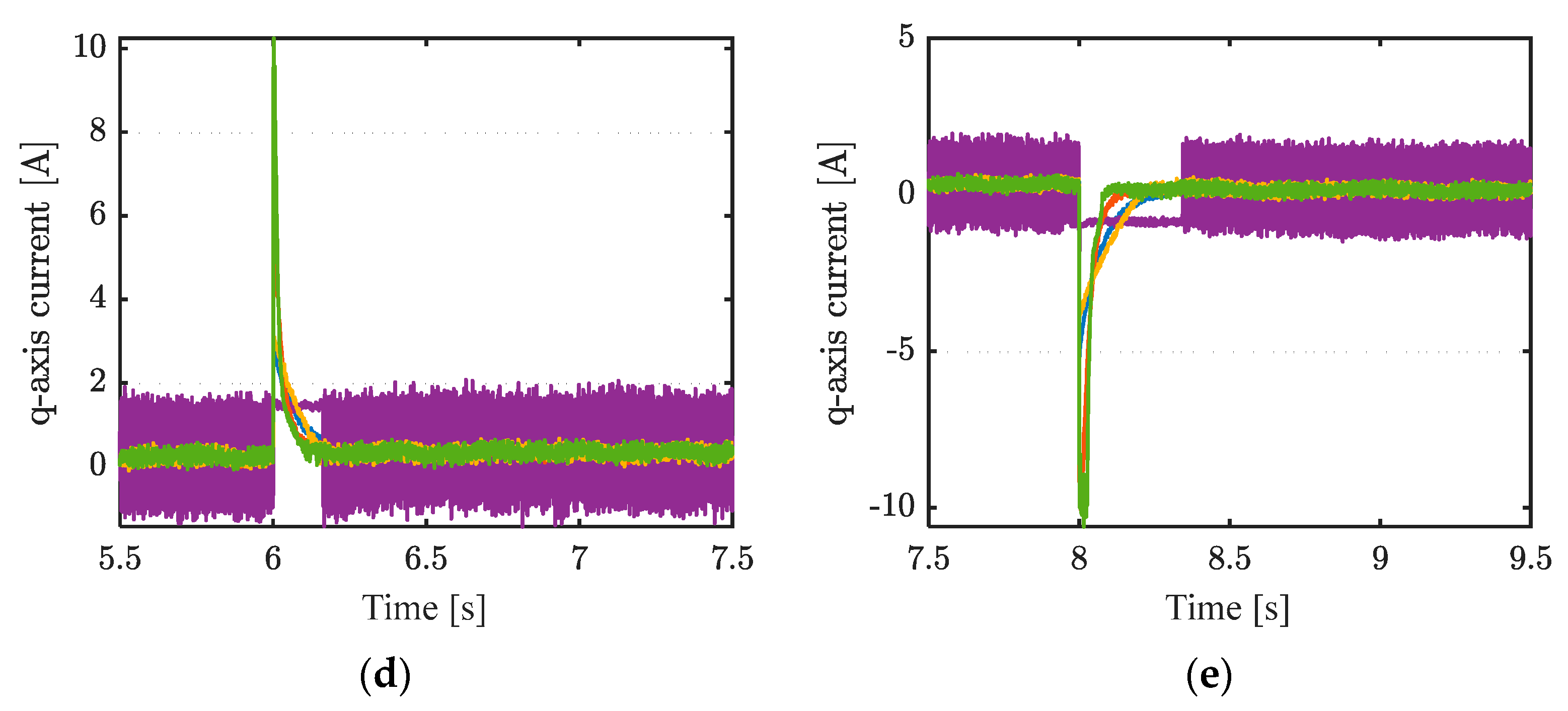
Figure 8 shows the current of the q-axis and local enlarged views. As can be seen, in a steady state, strategy #5 also has the smallest fluctuation.
The PI control-based strategy #1 not only has a longer tracking time and exhibits significant overshoot that is difficult to suppress, but its steady-state control accuracy is also far inferior to that of the sliding mode control-based strategies #2, #3, #4, and #5. The performance of strategy #2 is slightly better than that of strategy #1. Strategy #4, which uses the terminal sliding mode surface, and strategy #3, which uses the linear sliding mode, show that when the tracking error is relatively large, strategy #3 has a faster convergence speed. However, once the tracking error converges to a smaller range, the convergence speed of strategy #4 will be faster than that of strategy #3. Strategy #5 consistently maintains the fastest reference command response speed with almost no overshoot.
The integrated time absolute errors (ITAEs) of the five strategies are listed in
Table 4. Strategy #5 shows the smallest ITAE in all five time periods, with reductions of 61.6%, 50.4%, 50.6%, 60.1%, and 61.8% compared to strategy #4 in the respective time periods.
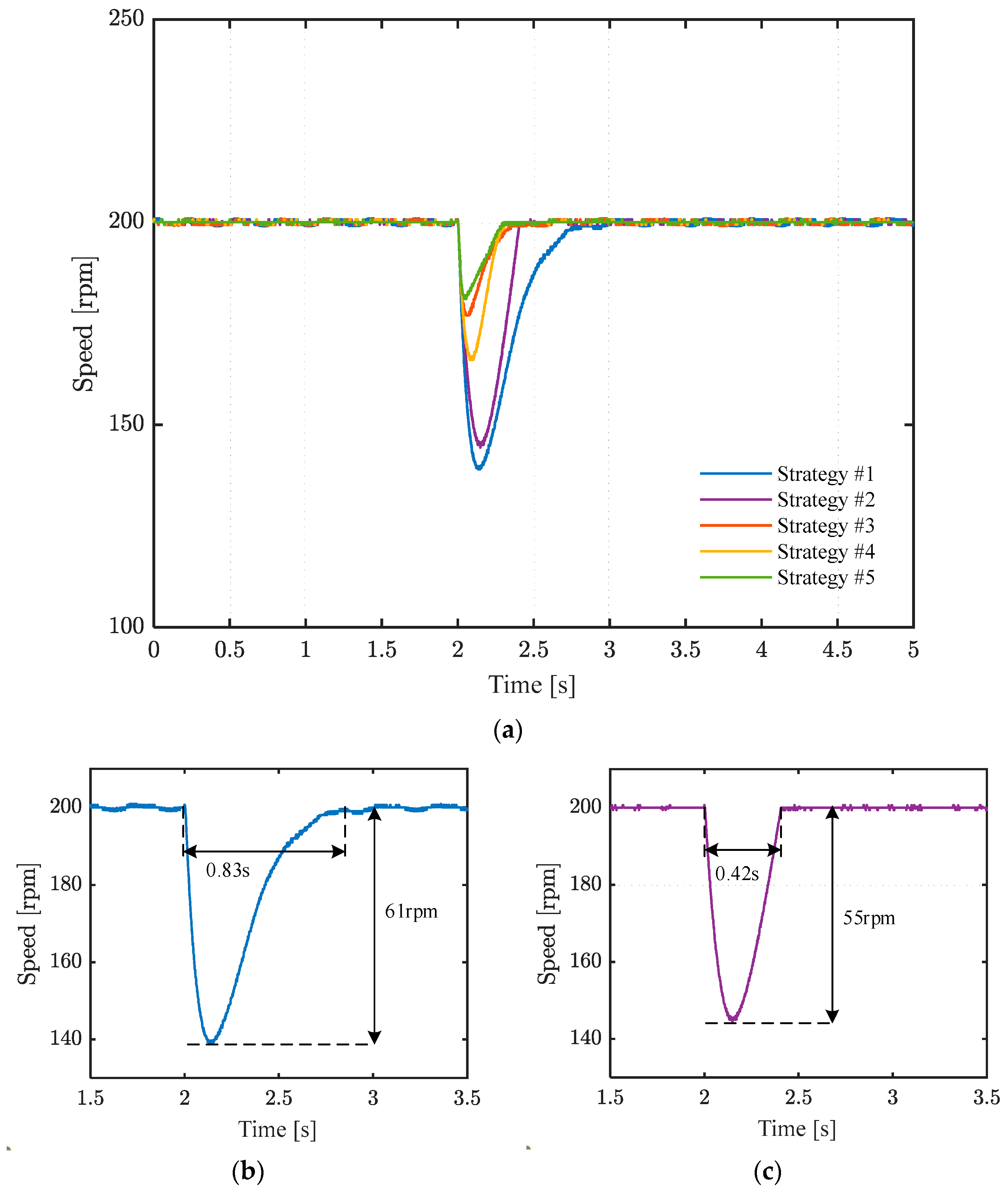
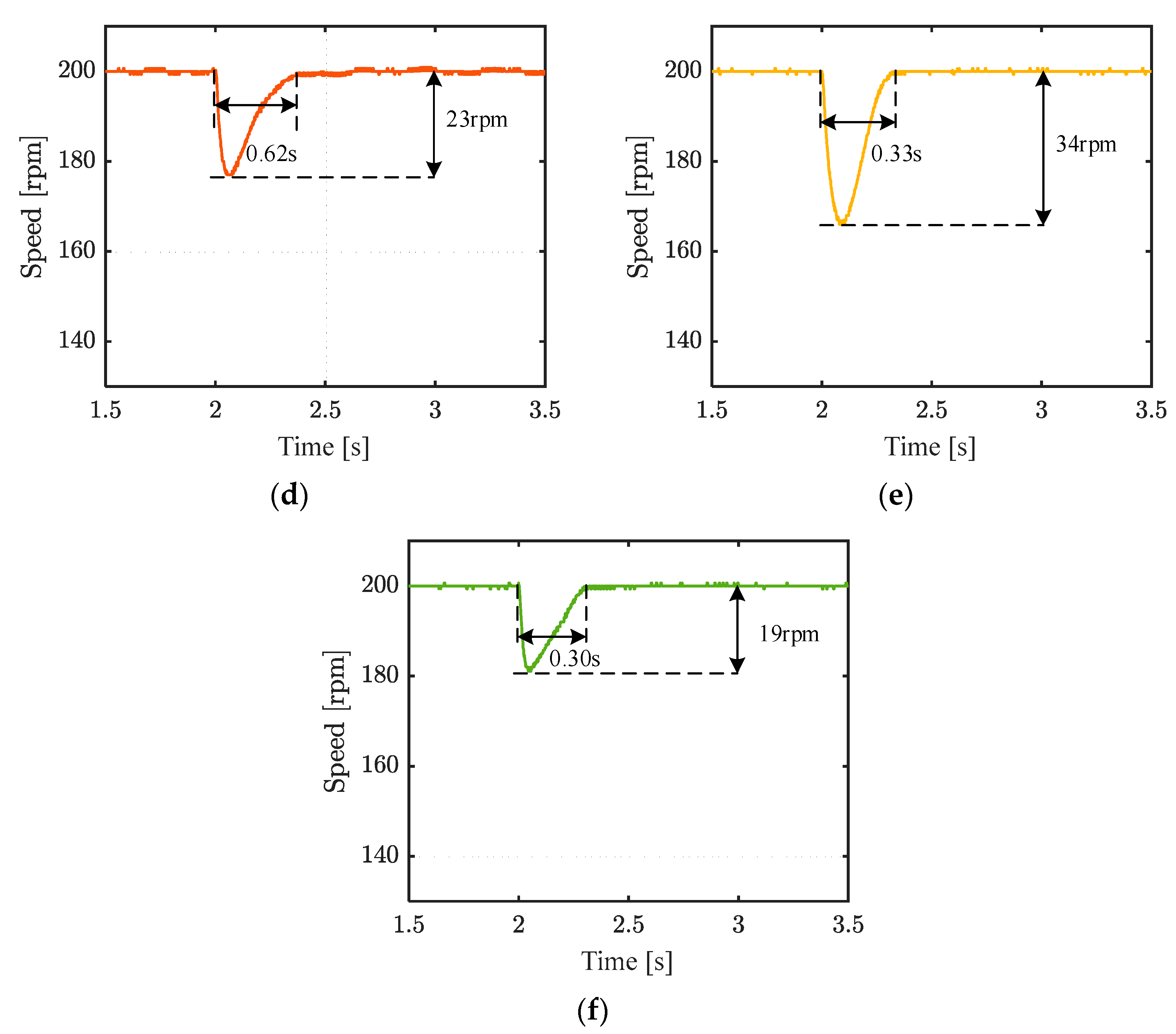
Figure 9 shows the speed of the five strategies under 200 rpm, and a 1 Nm load is applied at 2 s.
Figure 10 shows the q-axis currents of the five strategies under 200 rpm. Strategy #5 has the smallest speed drop at 19 rpm and the fastest recovery time at 0.3 s. The speed drops of the five strategies are 61 rpm, 55 rpm, 23 rpm, 34 rpm, and 19 rpm, respectively. The ITAEs of the four strategies are 50.8, 31.18, 10.7, 12.6, and 6.9, respectively. Strategy #1, using PI control, has the longest recovery time of approximately 0.83 s. The speed drop in strategy #2, which uses the traditional sliding mode control, is slightly smaller than that in strategy #1. The recovery time of strategy #2 is nearly 0.42 s. The speed drop in strategy #3 is slightly smaller than that in strategy #4, but its recovery time is nearly twice that of strategy #4. This is because the linear term provides higher gain when the speed tracking error is large compared to the terminal term, while it performs worse than the terminal term when the error is small. This is in line with the asymptotic convergence characteristic of the linear sliding mode surface and the finite-time convergence characteristic of the terminal sliding mode surface. Regardless of steady-state fluctuations, dynamic disturbance rejection, speed drop, or recovery time, the proposed strategy #5 shows the best performance. In terms of complexity, the proposed strategy, due to the incorporation of a switching mechanism, does not significantly increase the complexity compared to strategies #1–#4, demonstrating good performance.
