1. Introduction
The field of robotics faces a significant challenge in creating adaptable and flexible end-effectors, particularly in the context of modern manufacturing evolution. Industry 4.0, or the fourth industrial revolution, represents the next developmental stage in organizing the entire value chain process in the manufacturing industry [
1]. Among the nine pillars of Industry 4.0 identified by Suleiman et al., including autonomous robots, simulation, and additive manufacturing, three are particularly relevant to addressing current manufacturing limitations [
2].
Current robotic systems are predominantly implemented at an automated stage where the working environment is structured, object shapes and orientations are predetermined, and system adaptability is minimal [
1]. Consequently, existing robot end-effector combinations do not readily facilitate flexible manufacturing processes. This limitation creates a clear need for more adaptive robotic solutions.
Soft robotics, specifically soft robotic end-effectors, offer an innovative solution to these challenges. Fluid elastomeric actuators (FEAs) are commonly employed in soft robotic end-effectors due to their inherent adaptability [
3,
4,
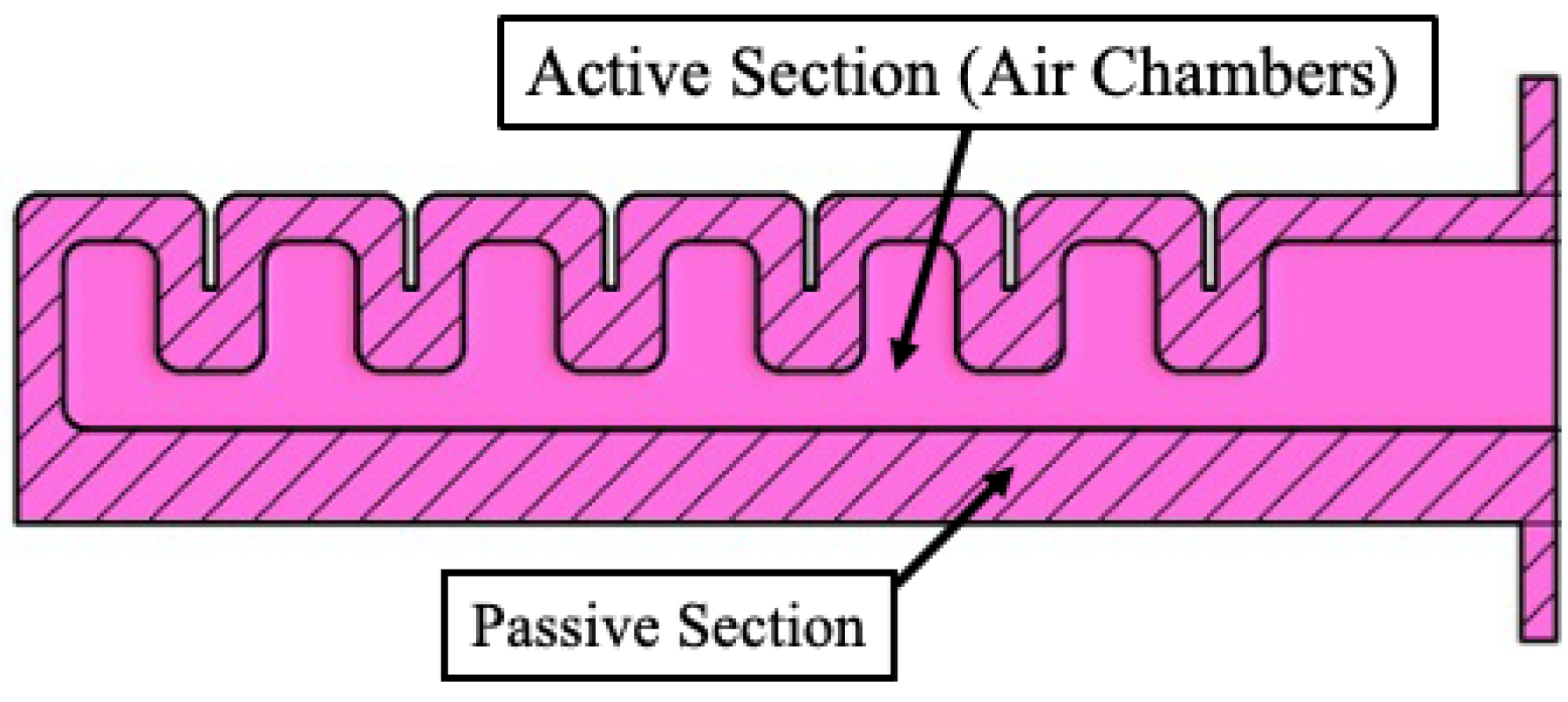
5]. These actuators consist of two fundamental sections: an active section typically manufactured from more elastic material and a passive section made from less elastic material [
6], as illustrated in
Figure 1. FEAs contain internal air chambers within their active sections, and when positive air pressure is applied, differential expansion rates between the sections create controlled bending toward the passive section due to the resulting eccentricity.
The design optimization of FEAs involves several critical considerations that directly influence their performance. Previous research has examined how air chamber shape affects performance, comparing triangular, trapezoidal, rectangular, and U-shaped configurations. Additionally, adjusting wall thicknesses alters section stiffness and flexibility, significantly impacting actuator performance. Understanding these design relationships is essential for developing application-specific solutions.
This paper presents a framework that combines systematic design parameter investigation with stress analysis for practical implementation. While individual design parameters have been studied previously, this work integrates stress distribution analysis alongside deformation performance to address actuator durability for industrial applications. The study demonstrates a FEM simulation methodology and concludes by proposing practical design guidelines for developing application-specific fluid elastomeric actuators. The study evaluates the use of Finite Element Method (FEM) simulations for optimizing FEA performance and concludes by proposing practical design guidelines for developing application-specific fluid elastomeric actuators.
2. Literature Review
2.1. Overview of Soft Robotics and FEAs
Soft robotics employs compliant materials to create adaptive robotic structures [
3,
4,
5,
7] that excel in unstructured environments due to their material composition. End-effectors incorporating soft actuators offer improved safety in human–robot interactions and require less precise grasp planning for component handling [
8].
While FEAs represent one approach to soft actuation [
3,
4,
5], alternative technologies offer different advantages and trade-offs. Fiber-reinforced actuators provide enhanced directional control and higher force output through embedded reinforcing fibers, enabling precise trajectory control and improved load-bearing capacity [
9,
10,
11]. However, these systems require more complex manufacturing processes and may exhibit reduced compliance compared to non-reinforced alternatives.
Origami-based soft actuators leverage geometric folding patterns to achieve complex motions with minimal material usage, offering lightweight solutions with predictable kinematics [
12,
13,
14]. Nevertheless, they typically provide limited force generation compared to pneumatic systems due to their reliance on geometric constraints rather than material expansion.
Jamming-enabled actuators utilize granular materials that transition between fluid and solid states under vacuum, providing variable stiffness capabilities and universal grasping adaptability [
15,
16,
17]. While these systems offer tunable compliance, they require additional vacuum infrastructure and may exhibit slower response times.
Each technology presents specific benefits for particular applications. However, FEAs maintain advantages in manufacturing simplicity, predictable pneumatic control, and the ability to achieve both sufficiently high force output and compliant interaction through straightforward material selection and geometric optimization.
2.2. Key Design Considerations
Four primary design considerations govern FEA development: the shape, size, number of air chambers, and the wall thickness of both active and passive sections [
3,
4,
5]. These parameters directly influence expansion performance, bending capability, and output force.
Previous research has examined how air chamber shape affects performance, comparing triangular, trapezoidal, rectangular, and U-shaped configurations. Rectangular chambers demonstrate the greatest expansion potential, while triangular chambers exhibit the least [
18]. Increasing air chamber size expands the inner surface area, potentially increasing output force. Additionally, adjusting wall thicknesses alters section stiffness and flexibility, significantly impacting actuator performance.
2.3. Challenges in FEA Design
Developing FEAs involves an iterative process where even minor design changes require mold modifications, making physical testing resource-intensive and time-consuming [
6]. Simulation software can accelerate this process, though modeling soft actuators presents challenges due to material non-linearity and complex geometries [
6,
19,
20,
21].
Elastomeric materials used in FEAs are hyperelastic, allowing for large deformations with minimal plastic deformation. This property results in complex mechanical behavior that linear elastic theory cannot adequately describe. Accurate modeling requires determining appropriate strain energy density function coefficients that match experimental data, necessitating the evaluation of multiple strain energy functions to identify the simplest model with sufficient accuracy.
FEM software enables researchers to develop hyperelastic material models that accelerate soft actuator design while reducing resource requirements for iterative testing and development.
Beyond material modeling challenges, FEA development faces additional complexities in control, sensing, and long-term performance. The non-linearity, complex geometries, and continuum nature of soft robots increase the difficulty and complexity of measuring and controlling these robotic structures [
22,
23]. Control strategies applicable to conventional robots are not necessarily relevant to soft robots, as traditional robots consist of rigid links and discrete joints [
22]. Hysteresis effects and sensor drift present significant challenges in dynamic applications, where sensor readings may not remain accurate over extended operation periods [
24]. Additionally, open-loop control strategies commonly used for FEAs are insufficient for accurately controlling the desired bending angles [
25]. Data-driven control techniques offer promising approaches that generate control strategies from physical motion data rather than predetermined models [
22], potentially addressing the inherent non-linearities in soft robotic systems.
3. Finite Element Method Approach
3.1. Purpose of FEM Simulations
The use of FEM simulations enables researchers to predict actuator performance without relying solely on physical prototypes. Thereby reducing resource consumption such as material and time. The purpose of this section is to investigate how selected FEM software can simulate the design considerations identified in
Section 2.2 and whether these simulations can optimize the design process of FEAs.
3.2. FEM Model Setup
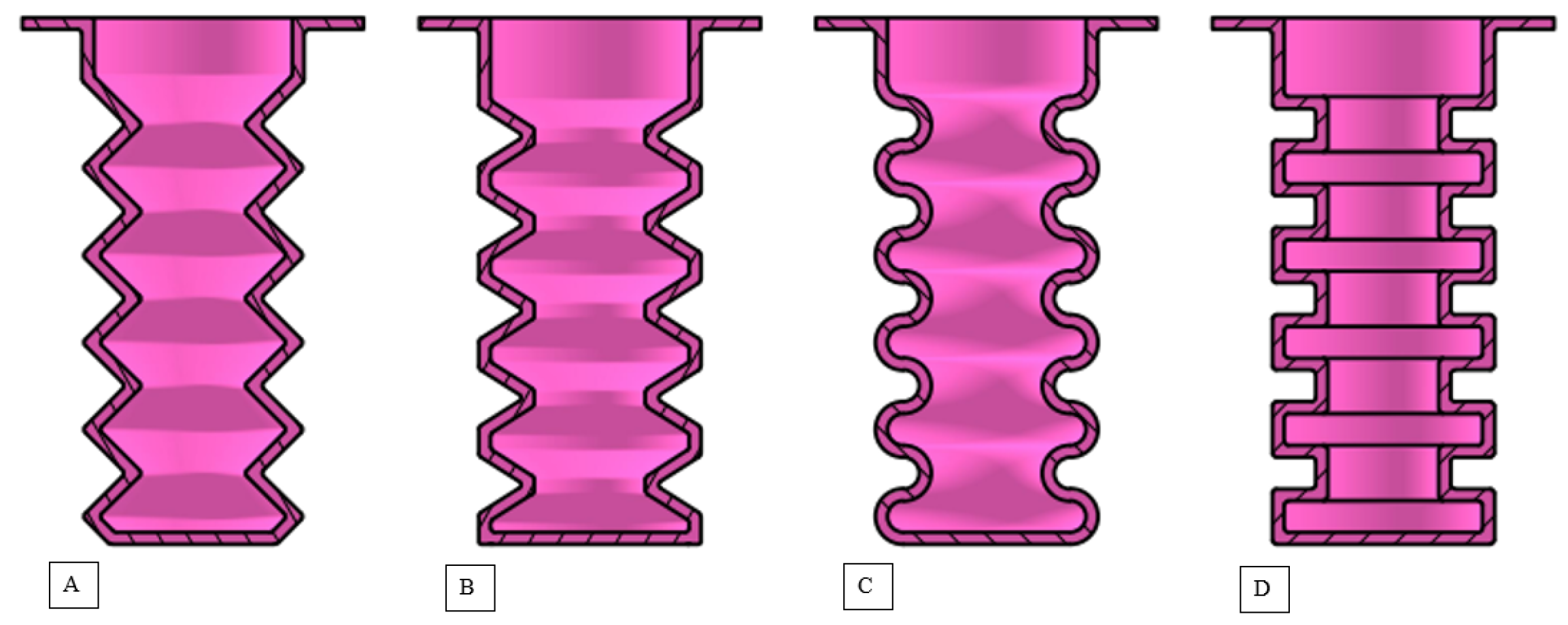
The FEM model was developed using ANSYS 2024 R1 software, with geometry based on the symmetric FEA Computer-Aided Design (CAD) models. Symmetric FEAs were developed to isolate the impact of each of the identified design considerations on the expansion performance of FEAs. To ensure controlled comparisons, all actuators were manufactured with identical baseline parameters except for the specific variable under investigation. All geometric studies utilized symmetric fluid elastomeric actuators with consistent wall thickness (3 mm), identical material properties (Mold Max 20), and the same overall actuator length. The primary performance metric evaluated was percentage expansion relative to the actuator’s unstrained position, measured as the vertical elongation when pressurized.
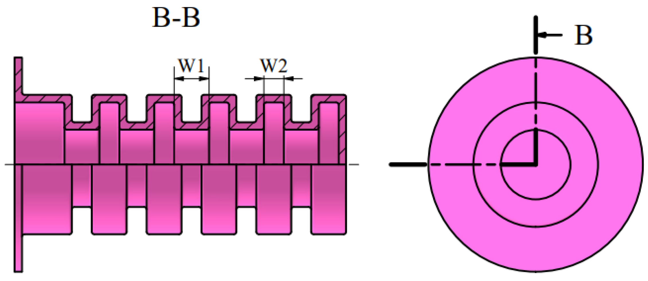
Figure 2 illustrates a sectional view of the FEAs developed to test the influence of air chamber shape.
A hyperelastic material model was developed based on uni-axial tension test data. The uni-axial tension tests were performed according to the ASTM D412 test standard, which covers the procedures used to determine the tensile properties of vulcanized rubber and thermoplastic elastomers [
26]. The ASTM D412 test standard is the same testing standard used by [
27] to develop a database of hyperelastic materials commonly used in soft robotics.
The elastomer used to manufacture the developed FEAs is known as Mold Max 20. This elastomer has a Shore A hardness of 20, a mixed viscosity of 25,000 centipoise, an elongation-at-break of approximately 512%, a tensile strength of 3.82 MPa, and a cure time of 20 h [
28]. Five ASTM D412 Type C tensile samples were cut from a ±2.3 mm thick sheet of Mold Max 20 elastomer.
The uni-axial tension tests were performed on a Zwick/Roell Z010 power-driven machine (ZwickRoell GmbH & Co. KG, Ulm, Germany) at an extension rate of 500 ± 50 mm/min. A 10 kN load cell measured the load with a sensitivity of 2 mV/V while a contact extensometer measured the elongation.
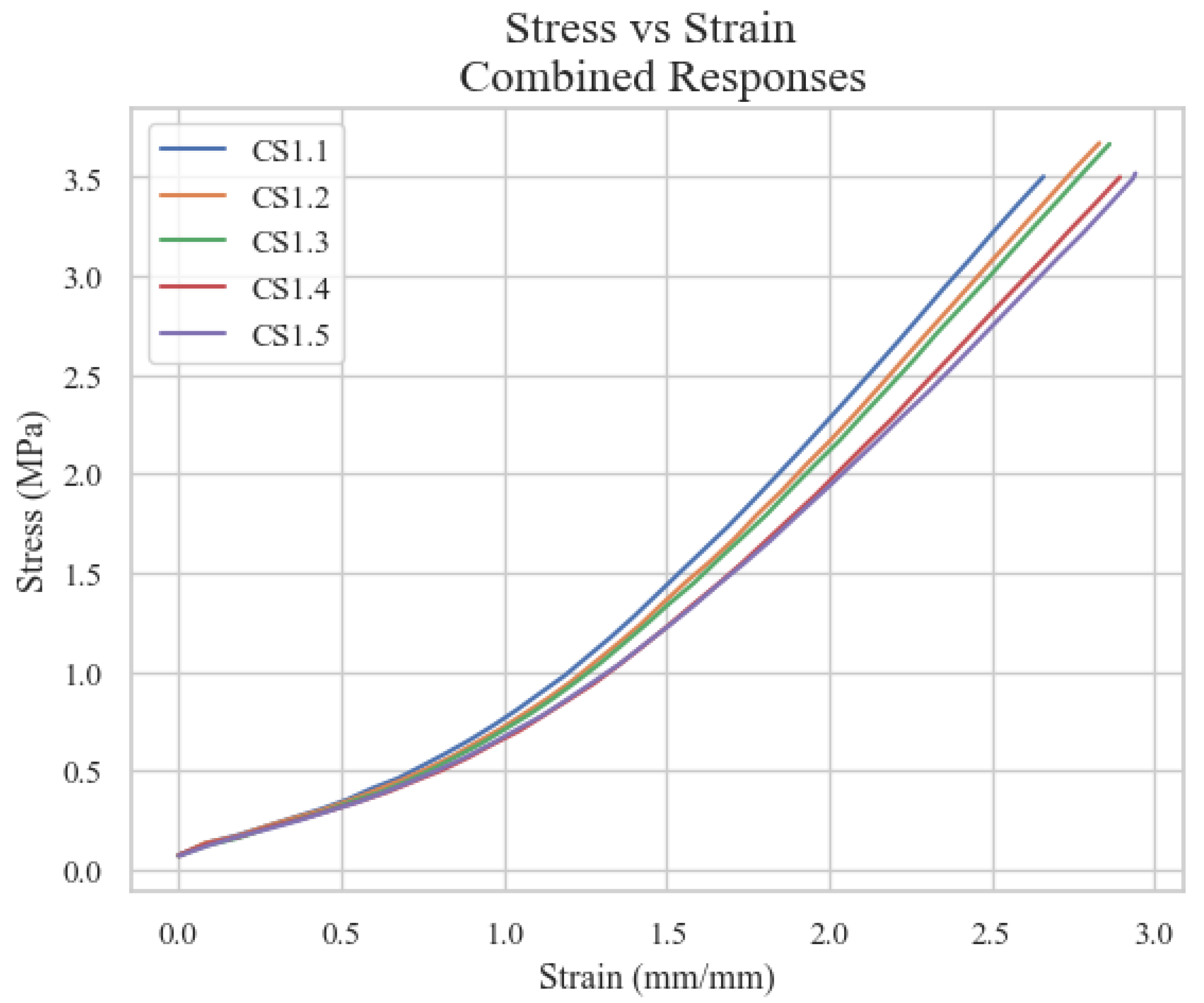
Figure 3 illustrates the tensile stress vs. strain data obtained from the uni-axial tension tests.
The results presented in
Figure 3 are then entered into ANSYS to determine the coefficients of the simplest hyperelastic material model providing adequate accuracy. Testing determined that the most accurate and stable hyperelastic models were the Yeoh Third Order and Yeoh Second Order models. These models could predict the stress–strain behavior of Mold Max 20 in different deformation modes from only uni-axial tension data, as suggested by [
29]. It has also been reported that these models are the most accurate for large-strain problems [
30,
31].
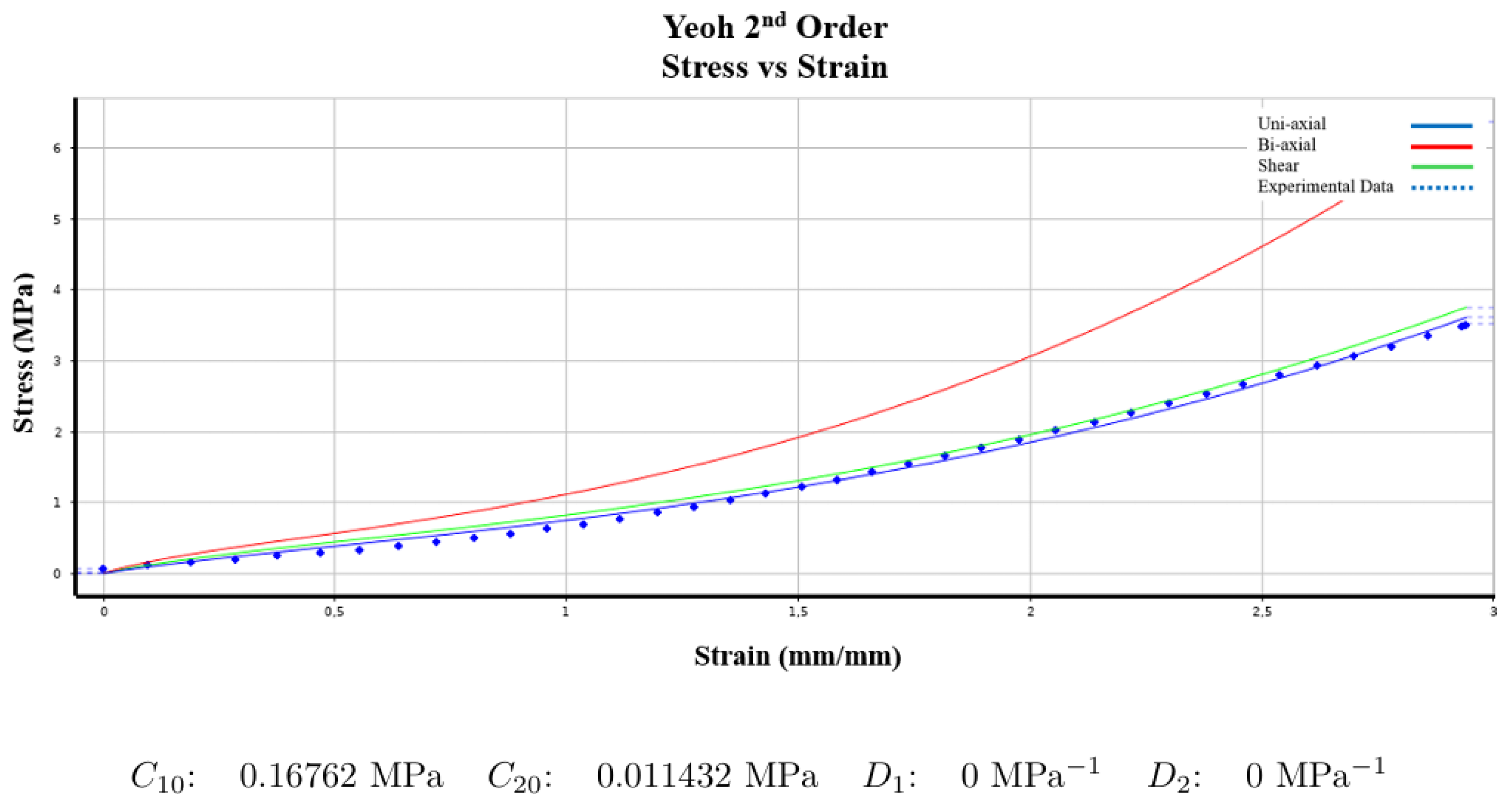
The Third Order Yeoh model achieved a normalized error value of 12,356, slightly lower than the Second Order model’s error value of 12,465. The Second Order Yeoh model was selected for simulating the design considerations identified in the literature because it has fewer parameters than the Third Order model while maintaining similar accuracy.
Figure 4 illustrates the experimental data for Specimen CS
1.5 alongside the Second Order Yeoh model and its coefficients.
3.3. Simulation Process
The FEM simulation followed a structured approach aligned with the methodology outlined by [
31]. Initially, CAD models were developed to address the previously identified key design considerations. A Static Structural study was established in ANSYS, implementing a hyperelastic material defined using the Second Order Yeoh model. After importing the CAD models into Design Modeler, the defined material properties were assigned and named selections were created for the inner and outer walls of the actuator. The mesh configuration utilized Non-linear Mechanical Physics Preference with Quadratic Element Order and a coarse mesh size of 0.3 m. Analysis settings incorporated auto time stepping (initial: 0.1 s, minimum: 0.0001 s, maximum: 1 s) with large deflections enabled. For boundary conditions, the top end of each actuator was fixed while gravity and a ramped internal pressure were applied to the inner walls. Additionally, a frictionless self-contact set was implemented on the outer walls. The 12 kPa pressure level was selected based on preliminary testing to ensure safe operation well below the material’s stress limits while providing sufficient deformation for comparative analysis. For the final application design, 40 kPa was chosen to meet the force requirements for automotive assembly applications while maintaining stress levels below 25% of the material’s tensile strength (3.82 MPa), ensuring durability for continuous industrial operation. The simulations evaluated total deformation, equivalent elastic strain, and equivalent stress. Upon solution completion in ANSYS, the results were prepared for further analysis.
4. Simulation Results
This section evaluates how FEM simulations can effectively model and optimize the key design parameters identified in
Section 2.2: air chamber shape, size, number, and wall thickness variations.
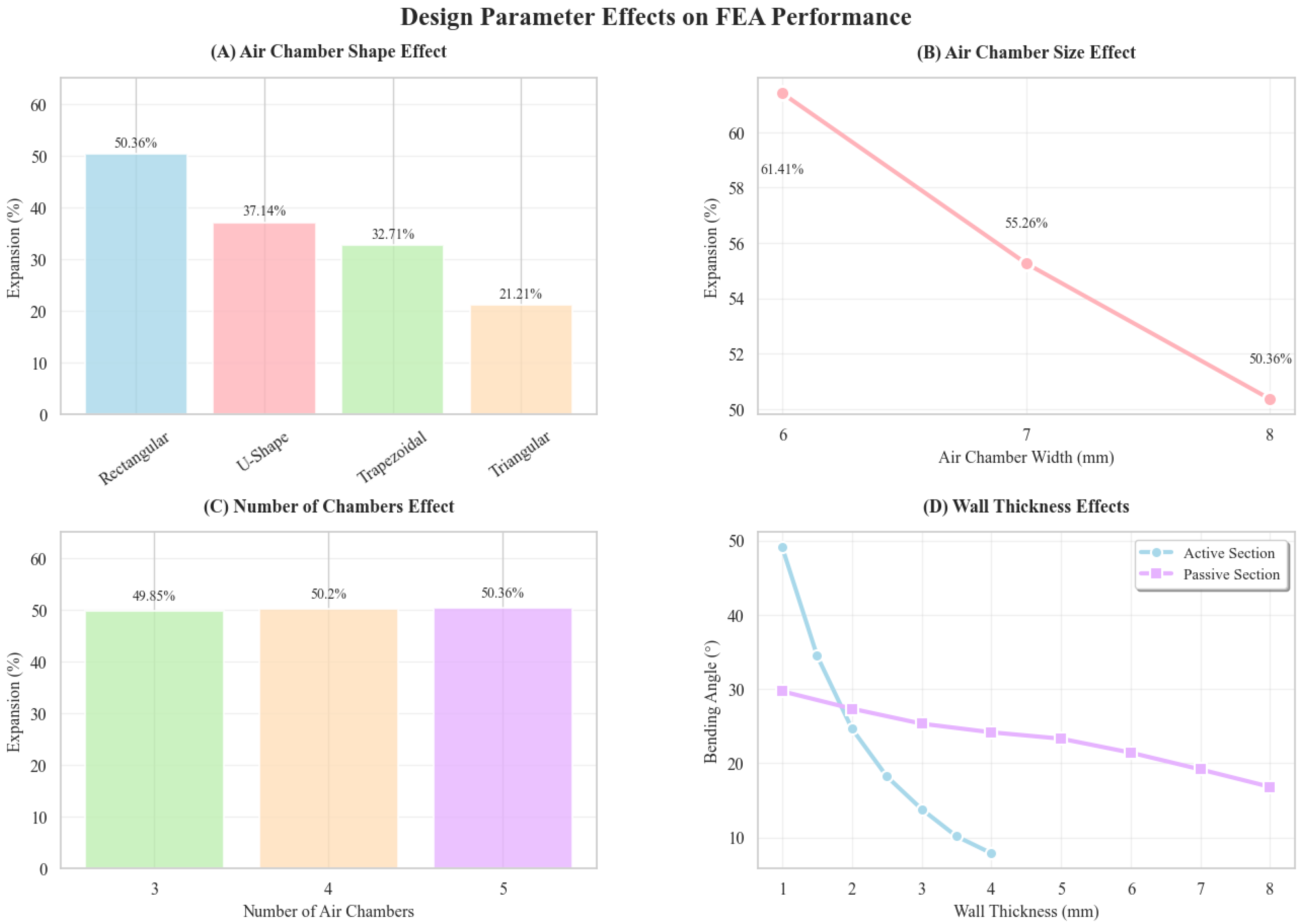
Figure 5 provides an overview of the key findings, with detailed numerical results presented in
Table A1,
Table A2,
Table A3,
Table A4 and
Table A5 in the
appendix. For shape comparison studies, all actuators maintained identical wall thickness, material properties, and number of air chambers (5), with only the air chamber geometry varying between triangular, trapezoidal, U-shaped, and rectangular configurations. For size variation studies, actuator shape, wall thickness, and material remained constant while only air chamber width was systematically altered. While overall actuator length and wall thickness remained consistent across comparisons, internal air chamber volume varied as intended, since volume changes are fundamental to the expansion performance being investigated. Note that this investigation focuses on reviewing the accuracy of the models created in this work, not the simulation software itself.
4.1. Geometric Variation
Four air chamber shapes were examined: triangular, trapezoidal, U-shaped, and rectangular. The results (
Table A1) show rectangular chambers achieve the greatest expansion (50.36%), while triangular chambers exhibit the lowest (21.21%). All configurations maintained stress levels well below the 3.82 MPa tensile strength of Mold Max 20, indicating safe operation under the applied pressure. Rectangular chambers are optimal for maximum deformation applications, while other shapes offer different balances of expansion and stress distribution.
4.2. Size Variation
The impact of air chamber width on performance was analyzed by decreasing chamber width from 8 mm to 6 mm in 1 mm increments (
Figure 6). As shown in
Table A2, smaller chambers achieved higher expansion percentages (61.41% at 6 mm vs. 50.36% at 8 mm), establishing an inverse relationship between chamber width and expansion capability. While stress levels increased slightly with smaller chambers, all designs remained within safe operational limits, highlighting a clear trade-off between maximizing expansion and managing stress.
4.3. Varying Number of Chambers
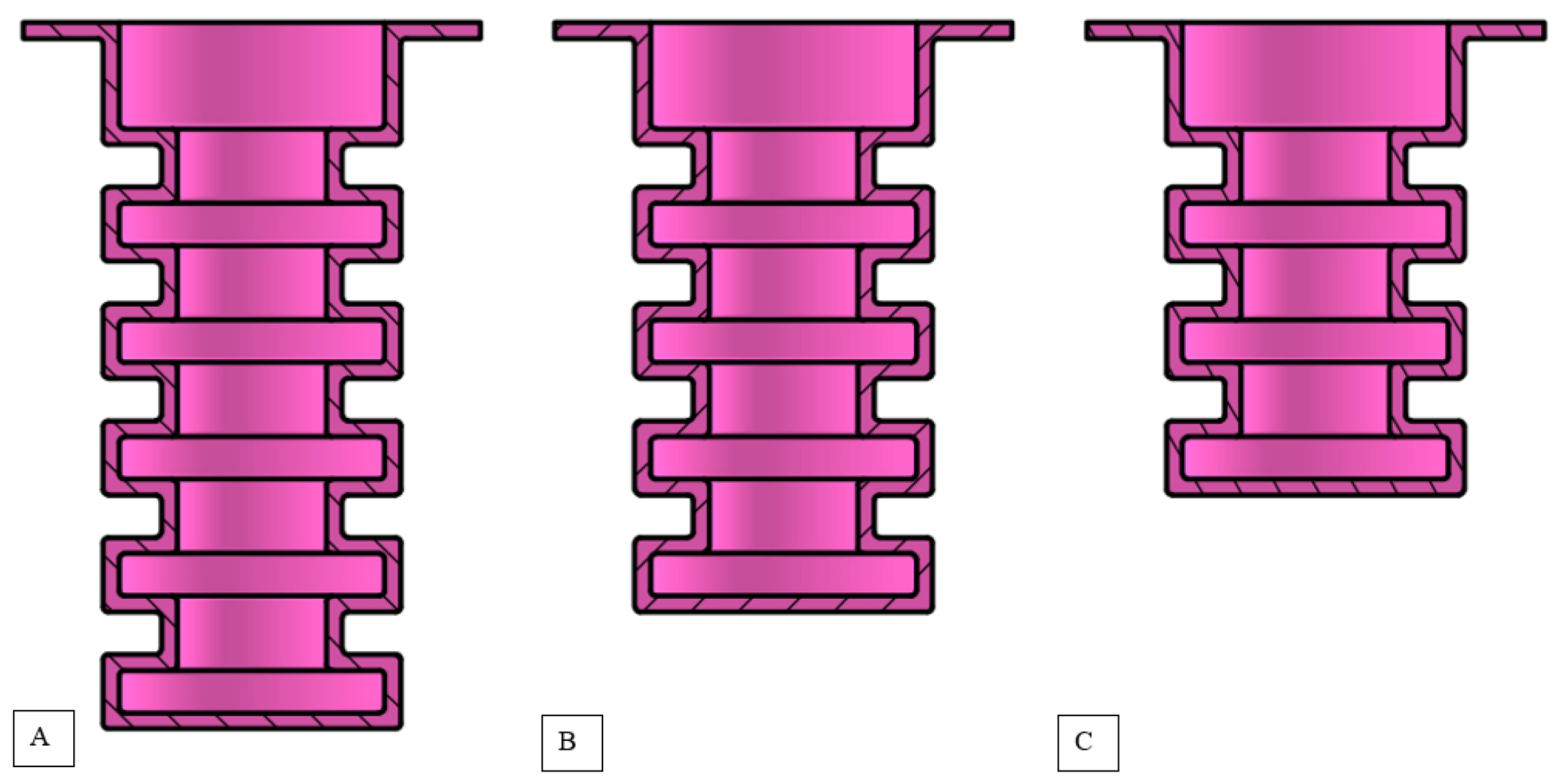
To examine the effect of the number of air chambers in an actuator, two additional symmetric FEAs were designed with varying numbers of air chambers, as shown in
Figure 7.
Table A3 illustrates the results obtained from the FEM simulations developed using the CAD models depicted in
Figure 7.
The results show a slight increase in the expansion percentage as the number of air chambers increases, indicating a directly proportional relationship between the number of air chambers and the achievable expansion. On average, the expansion percentage increases by 0.26% for each additional air chamber.
Actuators with three air chambers experience the highest stress, approximately 0.202 MPa, while those with four air chambers experience the lowest stress, around 0.201 MPa. Interestingly, even though the expansion percentage slightly increases with more air chambers, the variation in stress among the different configurations is minimal. This suggests that changing the number of air chambers in the actuator does not significantly affect the structural integrity of a symmetric fluid elastomeric actuator.
4.4. Varying Wall Thickness
The final key design consideration identified in
Section 2.2 is the impact of the wall thickness of the active and passive sections of FEAs. Following a methodology similar to that of [
18], the thickness of each section is varied independently. One section’s thickness is adjusted while keeping the other constant, and the process is then repeated with the roles reversed. This approach allows for a systematic evaluation of how the wall thickness of an actuator’s active and passive sections influences actuator performance.
The findings from investigating the impact of altering an actuator’s shape, size, and number of air chambers served as a guideline for designing a basic FEA, which could be used to investigate the fourth key design consideration.
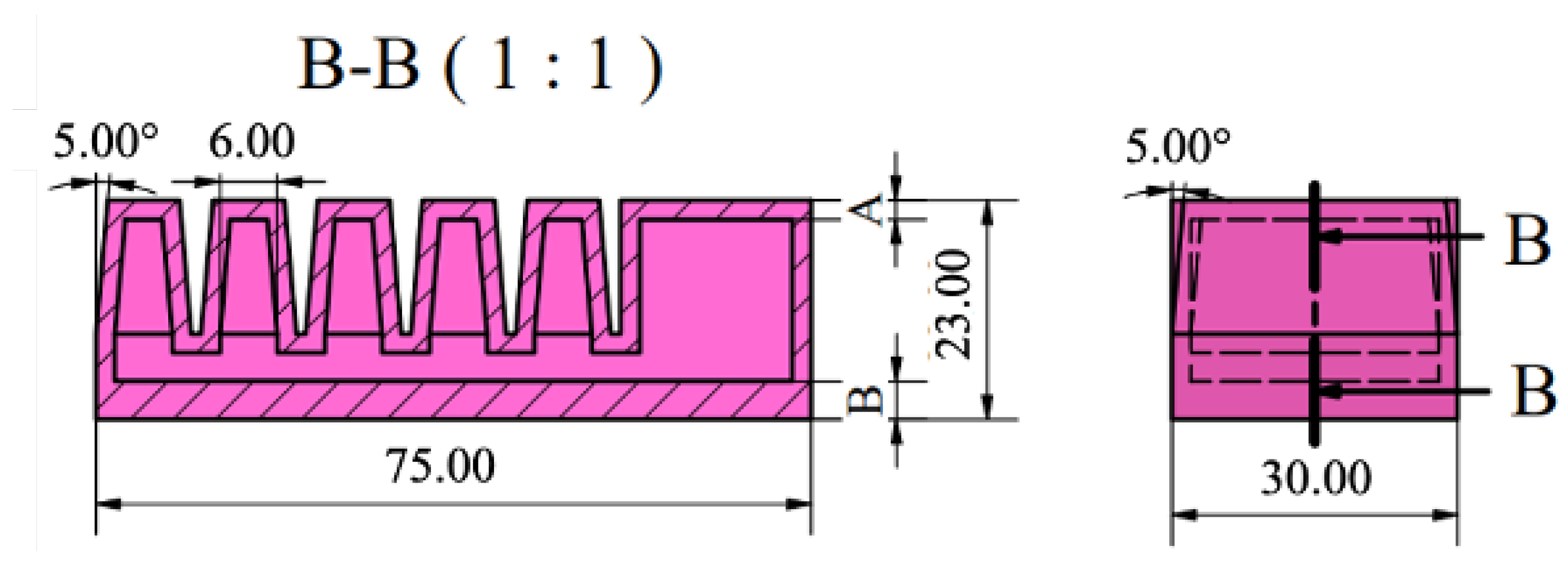
Figure 8 illustrates the designed FEA, with the active and passive section wall thickness denoted by A and B.
The designed actuator has a total length of 75 mm, a height of 23 mm, and a thickness of 30 mm. It includes five air chambers, each with a width of 6 mm. The rectangular-shaped air chambers have also been incorporated with a draft angle of 5 degrees to facilitate the manufacturing process and reduce the likelihood of errors during demolding.
4.4.1. Varying Active Section Wall Thickness
The predicted bending angles for different active section wall thicknesses, as determined through FEM simulation, are presented in
Table A4.
The data presented in
Table A4 indicate that increasing the wall thickness of an actuator’s active section reduces its bending angle. As a result, higher input pressure is required to achieve the same level of deformation. This trend is consistent with findings from the existing literature [
31,
32].
Moreover, as wall thickness increases, the equivalent stress decreases significantly, dropping from 0.600 MPa at a thickness of 1 mm to 0.092 MPa at 4 mm. This reduction can be attributed to the increased material resistance provided by thicker walls, which helps to distribute pressure more evenly and minimize stress concentrations.
These results support the notion that greater wall thickness enhances actuators’ resistance to bending. Therefore, designers must find a balance between performance—specifically, achieving a greater bending angle—and durability when developing FEAs for various applications.
4.4.2. Varying Passive Section Wall Thickness
Table A5 shows the results obtained from varying the wall thickness of the actuator’s passive section while maintaining a constant active section wall thickness of 2 mm.
The results presented in
Table A5 show a consistent decrease in the bending angle as the wall thickness of the passive section increases. Similar findings have been reported in the literature [
31,
32,
33]. Researchers attribute this trend to the increased stiffness of the actuator that occurs with thicker passive sections, which restricts its bending ability.
The stress values in
Table A5 illustrate slight fluctuations as the passive section thickness increases. However, there is a general trend of decreasing stress with greater thickness. This stress reduction suggests that thicker passive sections help distribute the applied pressure more evenly, thereby minimizing localized stress concentrations that could lead to material fatigue or failure. These findings imply that thinner passive sections may be more suitable for applications requiring higher bending angles and flexibility. In comparison, thicker passive sections may be more appropriate for applications prioritizing durability.
Table 1 summarizes the effects of key design parameters on actuator performance based on the FEM analysis results.
5. Application of Design Guidelines
Using the design insights from
Section 4, a flexible and adaptable soft robotic end-effector was developed specifically for automotive assembly applications where components with irregular shapes and burrs are common. The design prioritized both durability and sufficient bending capability for industrial environments.
For the actuator design, rectangular air chambers were selected based on their superior expansion performance (
Table A1). Five chambers were incorporated to enhance bending capability while maintaining structural integrity. The fifth chamber features a nearly triangular shape to improve handling of varied component geometries. A 1 mm spacing between chambers was implemented to minimize stress and prevent self-contact during operation.
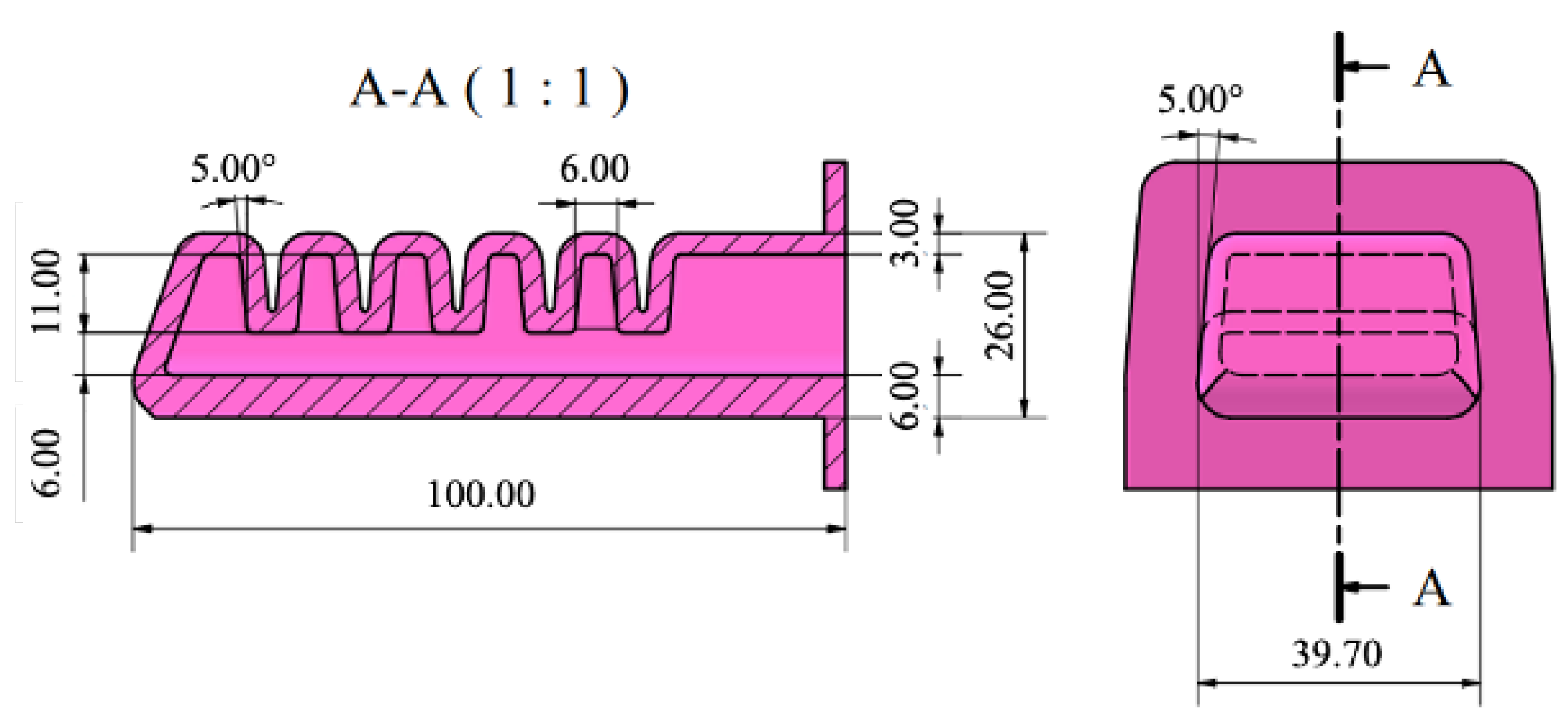
To ensure robustness for components with burrs, a passive section thickness of 6 mm was selected, accepting the associated reduction in bending angle. This was counterbalanced by using a thinner 3 mm active section wall to enhance bending performance while still providing adequate durability for continuous industrial operation. The air chambers were designed with a 6 mm width and a 5-degree draft angle to facilitate manufacturing and demolding.
The resulting actuator (
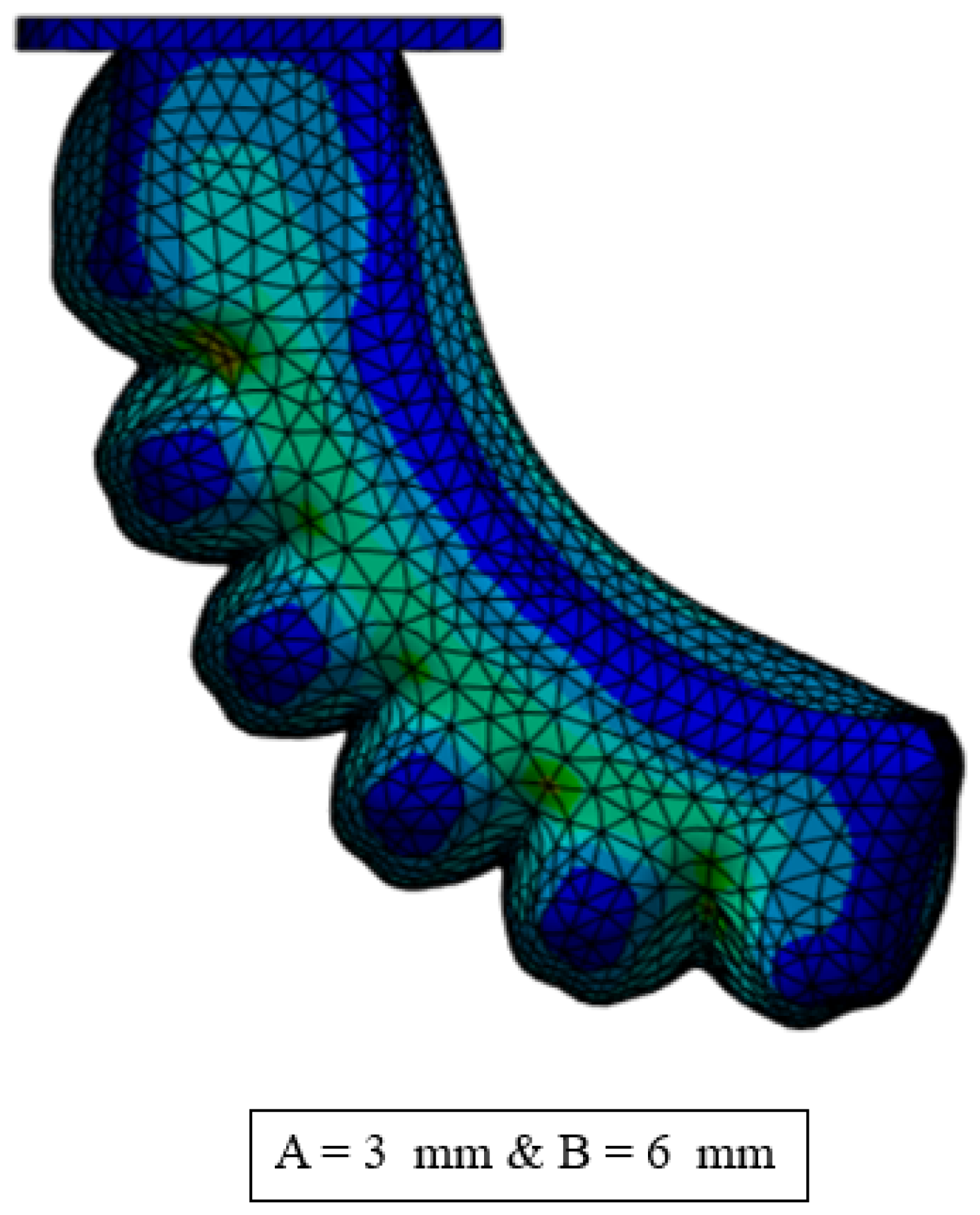
Figure 9) measures 100 mm in length, 39.70 mm in width, and 26 mm in height, with a rectangular cross-section at the base to facilitate pneumatic system connection. FEM simulations (
Figure 10) confirmed that the design could achieve the required bending performance under operating pressures while maintaining stress levels well below material limits.
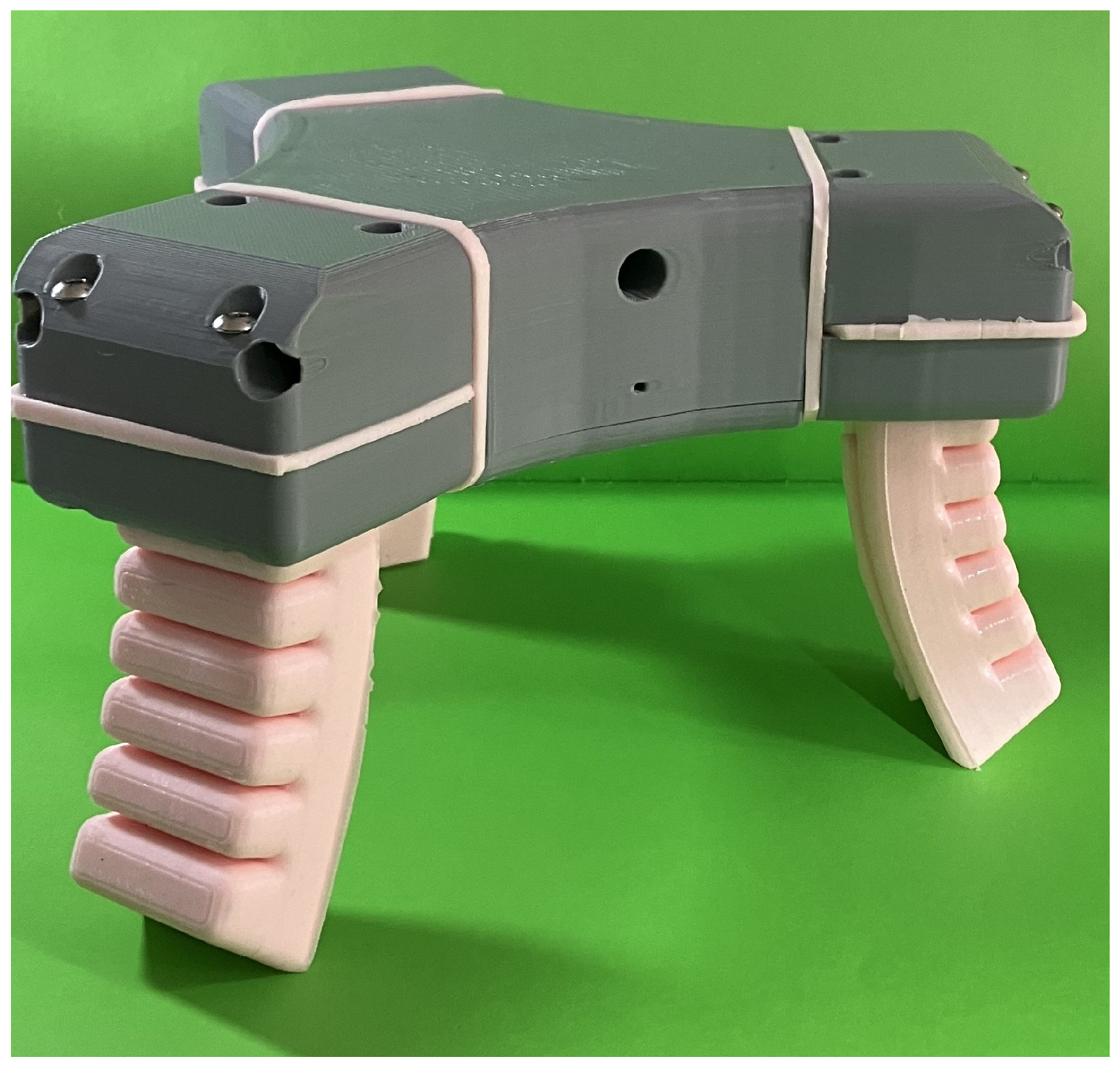
The final soft robotic end-effector assembly incorporating these optimized FEAs is shown in
Figure 11, demonstrating the practical application of our design principles in a functional gripper configuration for industrial use.
6. Conclusions
This study investigated fluid elastomeric actuators (FEAs) for soft robotic applications through a systematic analysis of key design parameters. FEM simulations revealed critical design trade-offs that inform actuator development: rectangular air chambers maximize expansion (50.36%) compared to triangular chambers (21.21%), while smaller chamber widths significantly increase expansion performance (61.41% at 6 mm vs. 50.36% at 8 mm). Increasing the number of air chambers offers marginal improvements in expansion capability (approximately 0.26% per additional chamber) without substantially affecting structural integrity.
Wall thickness analysis demonstrated a consistent inverse relationship between thickness and bending angle in both active and passive sections, with active section thickness having a more pronounced effect. The proposed actuator with 3 mm active and 6 mm passive section thicknesses balances flexibility and durability requirements for industrial applications, achieving sufficient bending performance while withstanding operational stresses.
While FEM simulations provide valuable design insights, real-world performance may diverge from simulations due to material variations and environmental factors.
This work contributes the following: (1) a combined deformation- and stress-based design approach for improved durability assessment, (2) systematic FEM methodology that can reduce the need for extensive physical prototyping, and (3) practical design guidelines derived from both performance and stress considerations for industrial applications such as automotive assembly.
Future work should focus on experimental validation of simulated designs and development of standard testing protocols for soft actuator performance. Additionally, integrating machine learning techniques with FEM simulations could enable automated optimization of actuator geometry for specific application requirements.
Author Contributions
Conceptualization, D.E. and T.v.N.; methodology, D.E.; software, D.E.; validation, D.E.; formal analysis, D.E. and T.v.N.; investigation, D.E.; writing—original draft preparation, D.E. and J.W.; writing—review and editing, J.W. and P.M.; visualization, D.E. and J.W.; supervision, T.v.N.; project administration, T.v.N.; funding acquisition, T.v.N. and P.M. All authors have read and agreed to the published version of the manuscript.
Funding
This research was funded by the Automotive Industry Development Centre Eastern Cape, (South Africa), and the Nelson Mandela University Postgraduate Research Scholarship.
Data Availability Statement
The original contributions presented in this study are included in the article. Further inquiries can be directed to the corresponding author.
Acknowledgments
During the preparation of this manuscript/study, the authors used Claude, Sonnet 4, for the purposes of language editing. The authors have reviewed and edited the output and take full responsibility for the content of this publication.
Conflicts of Interest
The authors declare no conflicts of interest.
Abbreviations
The following abbreviations are used in this manuscript:
| FEA | Fluid Elastomeric Actuators |
| FEM | Finite Element Method |
| CAD | Computer-Aided Design |
Appendix A. Detailed FEM Simulation Results
This appendix provides the detailed numerical results from the FEM simulations discussed in
Section 4.
Table A1.
Influence of changing the shape of an actuator’s air chambers FEM results (12 kPa).
Table A1.
Influence of changing the shape of an actuator’s air chambers FEM results (12 kPa).
Air Chamber
Shape | Expansion (%) | Simulation Results
Strain (mm/mm) | Stress (Pa) |
|---|
| Rectangular | | | |
| U-Shape | | | |
| Trapezoidal | | | |
| Triangular | | | |
Table A2.
Influence of changing the size of an actuator’s air chambers FEM results (12 kPa).
Table A2.
Influence of changing the size of an actuator’s air chambers FEM results (12 kPa).
Air Chamber
Size | Expansion (%) | Simulation Results
Strain (mm/mm) | Stress (Pa) |
|---|
| Size1 (8 mm) | 50.36 | 0.17632 | |
| Size2 (7 mm) | 55.26 | 0.1805 | |
| Size3 (6 mm) | 61.41 | 0.19127 | |
Table A3.
Influence of changing the number of air chambers in an actuator FEM results (12 kPa).
Table A3.
Influence of changing the number of air chambers in an actuator FEM results (12 kPa).
Number of Air
Chambers | Expansion (%) | Simulation Results
Strain (mm/mm) | Stress (Pa) |
|---|
| 5 Air Chambers | | | |
| 4 Air Chambers | | | |
| 3 Air Chambers | | | |
Table A4.
Predicted bending angle achieved for varying active section wall thicknesses while keeping passive section constant at 3 mm (12 kPa).
Table A4.
Predicted bending angle achieved for varying active section wall thicknesses while keeping passive section constant at 3 mm (12 kPa).
| Actuator Models | Simulation Results |
|---|
| Active Wall Thickness (mm) | Bending Angle | Stress (Pa) |
|---|
| Model 1.1 | 1 | | |
| Model 1.2 | 1.5 | | |
| Model 1.3 | 2 | | |
| Model 1.4 | 2.5 | | |
| Model 1.5 | 3 | | |
| Model 1.6 | 3.5 | | |
| Model 1.7 | 4 | | |
Table A5.
Predicted bending angle achieved for varying passive section wall thicknesses while keeping active section constant at 2 mm (12 kPa).
Table A5.
Predicted bending angle achieved for varying passive section wall thicknesses while keeping active section constant at 2 mm (12 kPa).
| Actuator Models | Simulation Results |
|---|
| Passive Wall Thickness (mm) | Bending Angle | Stress (Pa) |
|---|
| Model 1.1 | 1 | | |
| Model 1.2 | 2 | | |
| Model 1.3 | 3 | | |
| Model 1.4 | 4 | | |
| Model 1.5 | 5 | | |
| Model 1.6 | 6 | | |
| Model 1.7 | 7 | | |
| Model 1.8 | 8 | | |
References
- Pillay, K. Industry 4.0: Is Africa Ready for Digital Transformation? Tech. Rep.; Deloitte: Johannesburg, South Africa, 2016. [Google Scholar]
- Suleiman, Z.; Shaiholla, S.; Dikhanbayeva, D.; Shehab, E.; Turkyilmaz, A. Industry 4.0: Clustering of concepts and characteristics. Cogent Eng. 2022, 9, 2034264. [Google Scholar] [CrossRef]
- Zhang, H.; Liu, W.; Yu, M.-F.; Hou, Y. Design, fabrication, and performance test of a new type of soft-robotic gripper for grasping. Sensors 2022, 22, 5221. [Google Scholar] [CrossRef]
- Dang, H.M.; Vo, C.T.; Trong, N.T.; Nguyen, V.D.; Phung, V.B. Design and development of the soft robotic gripper used for the food packaging system. J. Mech. Eng. Res. Dev. 2021, 44, 334–345. [Google Scholar]
- Yap, H.K.; Ng, H.; Yeow, R.C.-H. High-force soft printable pneumatics for soft robotic applications. Soft Robot. 2016, 3, 144–158. [Google Scholar] [CrossRef]
- Els, D.; McLaren, J.; van Niekerk, T.; Phillips, R. Design, fabrication and analysis of a soft robotic gripper using fluid elastomeric actuators. In Proceedings of the 2023 14th International Conference on Mechanical and Intelligent Manufacturing Technologies (ICMIMT), Cape Town, South Africa, 26–28 May 2023; pp. 1–7. [Google Scholar]
- Walker, J.; Zidek, T.; Harbel, C.; Yoon, S.; Strickland, F.S.; Kumar, S.; Shin, M. Soft Robotics: A Review of Recent Developments of Pneumatic Soft Actuators. Actuators 2020, 9, 3. [Google Scholar] [CrossRef]
- Crowley, G.B.; Zeng, X.; Su, H. A 3D printed soft robotic gripper with a variable stiffness enabled by a novel positive pressure layer jamming technology. IEEE Robot. Autom. Lett. 2022, 7, 5477–5482. [Google Scholar] [CrossRef]
- Connolly, F.; Walsh, C.J.; Bertoldi, K. Automatic design of fiber-reinforced soft actuators for trajectory matching. Proc. Natl. Acad. Sci. USA 2017, 114, 51–56. [Google Scholar] [CrossRef]
- Polygerinos, P.; Correll, N.; Morin, S.A.; Mosadegh, B.; Onal, C.D.; Petersen, K.; Cianchetti, M.; Tolley, M.T.; Shepherd, R.F. Soft robotics: Review of fluid-driven intrinsically soft devices; manufacturing, sensing, control, and applications in human-robot interaction. Adv. Eng. Mater. 2017, 19, 1700016. [Google Scholar] [CrossRef]
- Hoque, M.A.; Petersen, E.; Fang, X. Effect of Material Properties on Fiber-Shaped Pneumatic Actuators Performance. Actuators 2023, 12, 129. [Google Scholar] [CrossRef]
- Li, S.; Vogt, D.M.; Rus, D.; Wood, R.J. Fluid-driven origami-inspired artificial muscles. Proc. Natl. Acad. Sci. USA 2017, 114, 13132–13137. [Google Scholar] [CrossRef] [PubMed]
- Paez, L.; Agarwal, G.; Paik, J. Design and analysis of a soft pneumatic actuator with origami shell reinforcement. Soft Robot. 2016, 3, 109–119. [Google Scholar] [CrossRef]
- Zaghloul, A.; Bone, G.M. Origami-Inspired Soft Pneumatic Actuators: Generalization and Design Optimization. Actuators 2023, 12, 72. [Google Scholar] [CrossRef]
- Brown, E.; Rodenberg, N.; Amend, J.; Mozeika, A.; Steltz, E.; Zakin, M.R.; Lipson, H.; Jaeger, H.M. Universal robotic gripper based on the jamming of granular material. Proc. Natl. Acad. Sci. USA 2010, 107, 18809–18814. [Google Scholar] [CrossRef]
- Amend, J.R.; Brown, E.; Rodenberg, N.; Jaeger, H.M.; Lipson, H. A positive pressure universal gripper based on the jamming of granular material. IEEE Trans. Robot. 2012, 28, 341–350. [Google Scholar] [CrossRef]
- Caro, F.; Carmichael, M.G. A Review of Mechanisms to Vary the Stiffness of Laminar Jamming Structures and Their Applications in Robotics. Actuators 2024, 13, 64. [Google Scholar] [CrossRef]
- Udupa, G.; Sreedharan, P.; Parvathaneni, P.S.D.; Kim, D. Asymmetric bellow flexible pneumatic actuator for miniature robotic soft gripper. J. Robot. 2014, 2014, 902625. [Google Scholar] [CrossRef]
- Pozzi, M.; Miguel, E.; Deimel, R.; Malvezzi, M.; Bickel, B.; Brock, O.; Prattichizzo, D. Efficient FEM-based simulation of soft robots modeled as kinematic chains. In Proceedings of the 2018 IEEE International Conference on Robotics and Automation (ICRA), Brisbane, Australia, 21–25 May 2018; pp. 4206–4213. [Google Scholar]
- Ding, L.; Niu, L.; Su, Y.; Yang, H.; Liu, G.; Gao, H.; Deng, Z. Dynamic finite element modeling and simulation of soft robots. Chin. J. Mech. Eng. 2022, 35, 24. [Google Scholar] [CrossRef]
- Suzumori, K.; Endo, S.; Kanda, T.; Kato, N.; Suzuki, H. A bending pneumatic rubber actuator realizing soft-bodied manta swimming robot. In Proceedings of the 2007 IEEE International Conference on Robotics and Automation (ICRA), Roma, Italy, 10–14 April 2007; pp. 4975–4980. [Google Scholar]
- Yasa, O.; Toshimitsu, Y.; Michelis, M.Y.; Jones, L.S.; Filippi, M.; Buchner, T.; Katzschmann, R.K. An overview of soft robotics. Annu. Rev. Control Robot. Auton. Syst. 2023, 6, 1–29. [Google Scholar] [CrossRef]
- García-Samartín, J.F.; Rieker, A.; Barrientos, A. Design, Manufacturing, and Open-Loop Control of a Soft Pneumatic Arm. Actuators 2024, 13, 36. [Google Scholar] [CrossRef]
- Elgeneidy, K.; Neumann, G.; Jackson, M.; Lohse, N. Directly printable flexible strain sensors for bending and contact feedback of soft actuators. Front. Robot. AI 2018, 5, 2. [Google Scholar] [CrossRef]
- Marchese, A.D.; Katzschmann, R.K.; Rus, D. A recipe for soft fluidic elastomer robots. Soft Robot. 2015, 2, 7–25. [Google Scholar] [CrossRef] [PubMed]
- ASTM D412-98a; Standard Test Methods for Vulcanised Rubber and Thermoplastic Elastomers: Tension. ASTM: West Conshohocken, PA, USA, 2002.
- Marechal, L.; Balland, P.; Lindenroth, L.; Petrou, F.; Kontovounisios, C.; Bello, F. Toward a common framework and database of materials for soft robotics. Soft Robot. 2021, 8, 284–297. [Google Scholar] [CrossRef]
- Smooth-On. Mold Max Series Condensation Cure Silicone Rubber Compounds; Smooth-On, Inc.: Macungie, PA, USA, 2024. [Google Scholar]
- Ali, A.; Hosseini, M.; Sahari, B. A review of constitutive models for rubber-like materials. Am. J. Eng. Appl. Sci. 2010, 3, 232–239. [Google Scholar] [CrossRef]
- Moseley, P.; Florez, J.M.; Sonar, H.A.; Agarwal, G.; Curtin, W.; Paik, J. Modeling, design, and development of soft pneumatic actuators with finite element method. Adv. Eng. Mater. 2015, 18, 978–988. [Google Scholar] [CrossRef]
- Xavier, M.S.; Fleming, A.J.; Yong, Y.K. Finite element modeling of soft fluidic actuators: Overview and recent developments. Adv. Intell. Syst. 2021, 3, 2000187. [Google Scholar] [CrossRef]
- Hu, W.; Mutlu, R.; Li, W.; Alici, G. A structural optimisation method for a soft pneumatic actuator. Robotics 2018, 7, 24. [Google Scholar] [CrossRef]
- Zhu, Y.; Feng, K.; Hua, C.; Wang, X.; Hu, Z.; Wang, H.; Su, H. Model analysis and experimental investigation of soft pneumatic manipulator for fruit grasping. Sensors 2022, 22, 4532. [Google Scholar] [CrossRef]
| Disclaimer/Publisher’s Note: The statements, opinions and data contained in all publications are solely those of the individual author(s) and contributor(s) and not of MDPI and/or the editor(s). MDPI and/or the editor(s) disclaim responsibility for any injury to people or property resulting from any ideas, methods, instructions or products referred to in the content. |
© 2025 by the authors. Licensee MDPI, Basel, Switzerland. This article is an open access article distributed under the terms and conditions of the Creative Commons Attribution (CC BY) license (https://creativecommons.org/licenses/by/4.0/).
