Abstract
Currently, soft robots face challenges such as low motion efficiency, susceptibility to damage in traditional silicone materials, and difficulty in achieving reproducible manufacturing. To address these issues, we integrate flexible film materials with modular design principles and apply them to soft robotics. Based on the concept of modularity, this study simplifies and decomposes the robot’s motion into three fundamental modules: a thin-film elongation actuator module, a thin-film deflection actuator module, and a connection module. Inspired by the Miura-fold origami technique and traditional lantern contraction, the elongation actuator is designed to produce axial extension of varying lengths under different air pressures. The deflection actuator is modeled after the head expansion mechanism of the pelican eel, enabling deflection movement. The connection module integrates the elongation and deflection modules into a unified structure. The research results show that the elongation actuator achieves an extension length of 118 mm under 50 kPa and can pull a 500 g load during horizontal contraction. The two-layer deflection actuator achieves a deflection angle of 56° at 40 kPa, while the three-layer version reaches 98°. For further demonstration, we subsequently conducted peristaltic soft robot experiments and obstacle avoidance experiments. This study holds significant potential for the development of next-generation multifunctional soft robots.
1. Introduction
Soft robots, a new class of robots, are typically fabricated from flexible materials with Young’s moduli ranging from 104 to 109 Pa [1,2], drawing inspiration from soft-bodied organisms in nature. Compared to conventional rigid robots, soft robots demonstrate superior environmental adaptability and enhanced human–robot interaction capabilities, enabling large deformations and high degrees of freedom [3,4,5,6,7]. Their ability to absorb most collision energy during motion significantly enhances operational safety [8,9]. Currently, most soft robots are constructed from silicone rubber, which presents challenges such as weight, bulkiness, manufacturing complexity, and sensitivity to environmental conditions such as temperature and humidity. These limitations result in reduced reliability, poor motion repeatability, and material aging, hindering the transition of soft robots from experimental settings to practical, real-world applications.
With the ongoing advancement of soft robotics, thin-film soft robots have demonstrated remarkable performance. Compared to conventional silicone-based soft robots, thin-film variants offer distinct advantages for practical applications, including greater deformability, enhanced environmental adaptability, lightweight and readily available materials, improved performance stability, and simpler motion planning and control.
In previous research on soft actuators, Jiachen Li et al. manufactured artificial muscles and structurally complex soft grippers by 3D printing. These soft actuators made from silicone elastomers can exhibit significant deformations and adapt to various complex environments [10]. In recent years, research on fabricating soft robots from various flexible film materials has grown significantly. Flexible films, widely used commercially for years, offer established reliability, safety, manufacturing infrastructure [11], and low cost, facilitating the transition of soft robots from laboratory prototypes to practical applications. Integrating flexible films with modular design in soft robotics holds substantial research significance. For instance, Rainier Natividad et al. from the National University of Singapore developed a reconfigurable pneumatic bending soft actuator [12]. This actuator consists of detachable airbag modules mounted on an elastic backing. By varying the number and type of airbags, the actuator achieves diverse bending angles. Cyclic testing confirmed its high reliability and consistency. Guoying Gu’s team created a thin-film pneumatic artificial muscle featuring a high contraction ratio and output force [13]. Comprising 15 load units, it can lift loads 250 times its own weight and achieve up to 87.5% contraction under a 200 g load. When arranged on a skeletal model, these muscles enabled rapid motions, such as throwing table tennis balls, showcasing the actuator’s fast response and explosive power. Reconfiguring actuator units also enabled versatile object grasping, demonstrating the superior kinematic performance of thin-film actuators.
In this study, we propose integrating the concept of modular design into the design of thin-film soft robots while drawing inspiration from the Miura-ori folding method and the expansion characteristics of the pelican eel’s head for biomimetic design [14,15]. The soft robot’s motion is decomposed into three core modules: a thin-film elongation actuator, a thin-film deflection actuator, and a connection module. The remainder of this paper is organized as follows: Section 2 describes the design and manufacture of each module; Section 3 demonstrates the performance of each actuator; Section 4 introduces the control module of the soft robot; and Section 5 verifies the feasibility of the overall design through peristaltic soft robot experiments and plane obstacle avoidance experiments. Finally, the content of this study is summarized.
2. Design of the Thin-Film Actuators
2.1. Design of the Thin-Film Elongation Actuators
Origami, the traditional art of folding flat paper into intricate two- or three-dimensional forms, has inspired numerous design strategies in soft robotics. It facilitates transitions between distinct folding states through external actuation. Common crease patterns, such as Miura-ori, Resch, and Kresling, have been widely applied in this field [16,17,18].
To achieve controllable axial elongation and linear motion in thin-film soft robots, this study introduces a design approach inspired by the Miura-ori folding pattern. Mimicking the traditional folding lantern, a thin-film elongation actuator was developed. As illustrated in Figure 1A, the actuator consists of square-shaped, single-layer TPU airbag modules connected in series, with a total side length of L and a variable number of layers denoted by n. Each pair of airbags is joined by a connector cavity centered within the actuator’s outer contour, sized a × b. Two cross-arranged vertical stiffeners (width s) are integrated to enhance expansion stability and contraction efficiency. The welding widths at the connector and outer edge are denoted by δ1 and δ2, respectively.
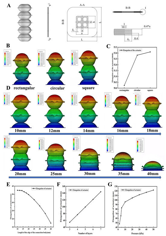
Figure 1.
The design and simulation optimization of the thin-film elongation actuators. (A) The design diagram of the thin-film elongation actuator. (B) The simulation cloud diagrams of different connector shapes. (C) The relationship between connector shapes and elongations. (D) The simulation cloud diagrams of different side sizes. (E) The connector edge length–elongation relationship curves. (F) The relationship curve between the number of layers and the elongation amount. (G) The relationship curve between air pressure and the elongation amount.
The primary performance metric is axial elongation, which is influenced by the connector shape, the connector dimensions, and the number of airbag layers (n).
We evaluated three connector geometries—square, rectangular, and circular—while keeping all other variables constant (i.e., n = 3, rib width = 3 mm, pressure = 30 kPa, equal cavity area). The square connector (12 × 12 mm) produced 53.1 mm elongation, the rectangular one (8 × 18 mm) yielded 50.23 mm elongation, and the circular connector (⌀13.5 mm) reached 52.82 mm elongation. These results (Figure 1B,C) indicate that the square connector provides the most efficient elongation, making it the focus of subsequent analysis.
Using square connectors, we tested side lengths from 10 mm to 40 mm (at 3 mm rib width, 3 layers, 30 kPa). The results (Figure 1D,E) show that elongation decreases as connector size increases, with the rate of decrease accelerating beyond 14 mm. Below 14 mm, deformation becomes unstable, particularly at 12 mm. Thus, 14 mm was chosen as the optimal size, balancing elongation and structural stability.
With a fixed connector size (14 mm) and rib width (3 mm), we simulated actuators with 3–7 layers under 30 kPa. The results (Figure 1F) show a consistent increase of approximately 22.4 mm elongation per added layer, with minimal error (<0.15 mm). A 5-layer actuator achieved 99.23 mm elongation, providing a balance of performance and flexibility for modular integration. Simulations fixing only a 14 × 14 mm base area show that elongation increases with air pressure, though the growth rate tapers off. At 50 kPa, elongation reaches 121.9 mm (Figure 1G), confirming that the actuator meets the design objectives. These findings offer theoretical support for further applications.
Based on the results of the comparative analysis and optimization of the simulation mentioned above, the specific design parameters for the film-type elongation actuator are presented in Table 1. During manufacturing, the thermal bonding widths δ1 and δ2 at the connection body and around the external profile are both set to 2 mm, in accordance with the actual process standards and mold design manufacturing capabilities.

Table 1.
Design parameters for the sizes of thin-film elongation actuators.
As illustrated in Figure 2 below, molds for the thin-film elongation actuators have been designed and manufactured, and the manufacturing process has been scheduled. The detailed Manufacturing Process Flow can be found in the Supplementary Materials.
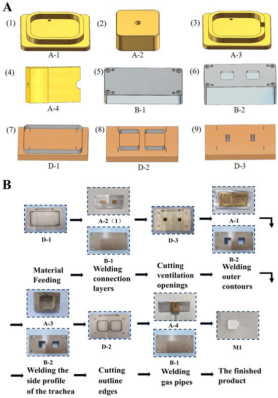
Figure 2.
The planning and manufacturing process of the thin-film elongation actuators. (A) The manufacturing molds for the thin-film elongation actuators: (1) the outer contour mold; (2) the intermediate connector mold; (3) the air tube side outer contour welding mold; (4) the air tube connection welding mold; (5) the positioning lower mold; (6) the positioning hollow lower mold 1; (7) the material cutting die; (8) the module outer contour cutting die; (9) the connector cutting die. (B) The manufacturing process of the thin-film elongation actuators.
2.2. Design of the Thin-Film Deflection Actuators
Traditional deflection motion typically refers to the rotation of an object around a single axis, as seen in everyday mechanisms like hinges, in nature (e.g., scallop shells), and in the human body (e.g., finger joints) [19]. This study presents a bioinspired design based on the head expansion mechanism of the pelican eel, which involves both the axial rotation of the mouth’s outer contour and the expansion of its flexible skin [15]. This dual-mode deformation significantly enhances its prey-capturing efficiency.
Inspired by this mechanism, a thin-film deflection actuator was developed. It operates by constraining one side of the actuator while leaving the opposite side free. Upon inflation, a displacement differential is created between the two sides, causing the upper surface to rotate relatively to the fixed lower surface, resulting in deflection around a fixed edge.
As illustrated in Figure 3A, the actuator has a square outer contour with side length (L) and consists of multiple interconnected single-layer TPU film airbags. The number of airbag layers is denoted by n, with the deflection angle increasing as n increases. One side of the actuator is welded and fixed over an area of size c × f. Between every two airbags lies a connector cavity, located at a distance d from the fixed edge, with dimensions a × b. Two perpendicularly crossed stiffeners (width s) are incorporated to enhance mechanical integrity. The hot-pressed welding widths at the connector and outer contour are denoted by δ1 and δ2, respectively.
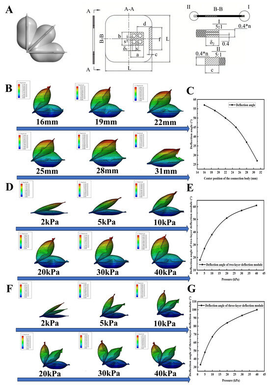
Figure 3.
The design and simulation optimization of the thin-film deflection actuators. (A) The design diagram of the film-type deflection actuator. (B) The simulation cloud diagrams of the connector position. (C) The relationship curve between connector position and deflection angle. (D) The simulation cloud diagrams of the two-layer deflection module with variations in air pressure. (E) The relationship between air pressure and deflection angle for the two-layer deflection module. (F) The simulation cloud diagrams of the three-layer deflection module with variations in air pressure. (G) The relationship between air pressure and deflection angle for the three-layer deflection module.
The key performance metric is the deflection angle between the actuator’s upper and lower surfaces. Using a two-layer actuator model, simulations were conducted under an input pressure of 30 kPa to evaluate the effect of connector position. The connector’s center was placed at distances of 16 mm, 19 mm, 22 mm, 25 mm, 28 mm, and 31 mm from the fixed edge. All other variables were held constant. As shown in Figure 3B,C, the deflection angle is maximized when the connector is positioned 16 mm from the fixed edge, with the angle progressively decreasing as this distance increases.
Based on these findings, a connector placement of 16 mm was selected for further optimization. Simulations were then conducted for two-layer and three-layer actuators under varying air pressures ranging from 2 kPa to 40 kPa, and their corresponding deflection angles were recorded. As shown in Figure 3D–G, deflection angle increases with pressure, though the rate of increase diminishes at higher pressures. At 40 kPa, the two-layer actuator achieves a deflection angle of 61°, while the three-layer actuator reaches 100°.
These results suggest that the two-layer design is more suitable for small-angle, fine-controlled deflection tasks. In contrast, the three-layer version enables larger deformations with lower pressure input, though its precision at small angles is reduced. Understanding these characteristics through simulation enables better actuator design and task-specific deployment.
During the manufacturing process, the hot-press welding widths at the connectors and the surrounding outer profile, δ1 and δ2, are both set to 2 mm based on actual process standards and the molding design and manufacturing capabilities. The outer profile length L is 50 mm, the connector shape is square with a side length of 14 mm, and the width of the reinforcing rib(s) is 3 mm. These parameters are consistent with the relevant parameters of the elongation module, aiming to achieve a larger expansion volume and greater deformation. Based on the results of the aforementioned simulation optimization study, the remaining core design parameters of the thin-film deflection actuator are shown in Table 2 below.

Table 2.
Design parameters for the sizes of thin-film deflection actuators.
As illustrated in Figure 4 below, molds for the thin-film deflection actuators have been designed and manufactured, and the manufacturing process has been scheduled. The detailed Manufacturing Process Flow can be found in the Supplementary Materials.
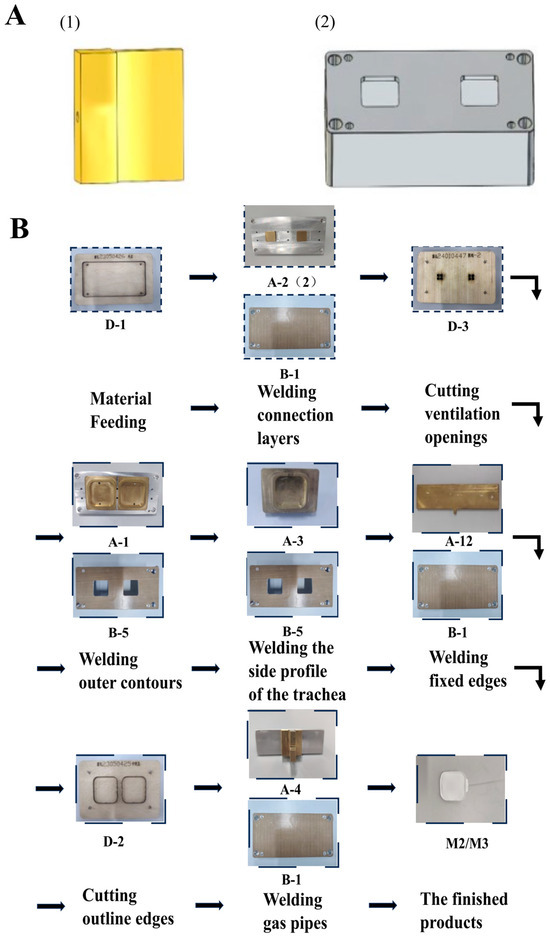
Figure 4.
The planning and manufacturing process of the thin-film deflection actuators. (A) The manufacturing molds for the deflection modules: (1) the side-fixed welding mold; (2) the positioning hollow lower mold 2. (B) The manufacturing process of the thin-film deflection actuators.
2.3. Design of the Connection and Disconnection Modules
The connector base for the square foam has Velcro on all six sides, with the Velcro size matching the surface area of the square foam as shown in Figure 5A. Each thin-film actuator is connected at the center of the connection surface with Velcro, which is sized to match the dimensions of the module’s central connection body (14 mm × 14 mm). This design minimizes the impact of deformation on the expansion of the connection body. To enhance the soft robot’s operational flexibility, this study investigates the separation of the connection module. By connecting a single layer of airbags to both sides of the connection body, the two modules can be separated by controlling the inflation of the central airbags. For the separation needs of the airbag design verification, tensile experiments were conducted (Figure 5B,C). The results show that, when the Velcro gap reaches 6 mm, peeling occurs. Given the 14 mm × 14 mm size of the Velcro connection, a cavity of 16 mm × 16 mm is required for the separation mechanism (Figure 5D). The connection method between the connecting module and the separation airbags is illustrated in Figure 5E. The contact stress between the two airbags is shown in Figure 5F. Simulation results indicate that, when 40 kPa of pressure is applied, the two single-layer airbags can create a displacement of 9.4 mm, allowing the module to separate (Figure 5G).
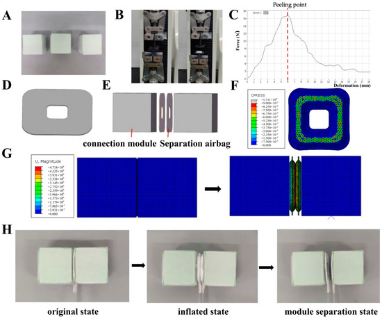
Figure 5.
The design of the connection and disconnection modules. (A) The connection module. (B) The Velcro tensile experiment. (C) The tensile curve. (D) The single-layer airbag model. (E) The exploded diagram of the assembly method. (F) The stress diagram of the contact surface of the inflated separation airbag. (G) The simulation cloud diagrams of expansion separation. (H) The connection module segmentation experiment.
Subsequent experimental validation (Figure 5H) confirms that the separation of the two connected modules can be achieved using two single-layer airbags. This provides feasible support for the subsequent self-reorganizing segmentation motion of the thin-film modular soft robot.
3. Performance Testing of the Thin-Film Actuators
3.1. Performance Testing of the Thin-Film Elongation Actuator
This article focuses on performance testing aimed at evaluating whether the actual elongation of actuator modules aligns with the simulation trends. A simple elongation testing platform was constructed, as shown in Figure 6A. This platform consists of the following components: (1) a fixed platform with a contact surface fitted with Velcro to adhere and secure the thin-film elongation actuator, simulating the primary fixation method during operational processes; (2) a measuring instrument—a ruler; (3) a pneumatic control box to control and adjust the input air pressure; and (4) an air pump to provide the air source. During the experiment, the input air pressure for the elongation actuator was sequentially increased from 2 kPa to 50 kPa (as shown in Figure 6C), recording its elongation. This process was repeated ten times to obtain an average value, with the standard deviation of the measured data approximately 1 mm. From the experiment and the measured data, it can be observed that, during pressurization expansion, the multilayer airbags of the thin-film elongation actuator expand almost synchronously, and the elongation increases with the rising air pressure. When the input air pressure is below 10 kPa, the rate of elongation growth is relatively high; however, when the air pressure exceeds 30 kPa, the growth rate of elongation decreases significantly. Ultimately, when the input air pressure increases to 50 kPa, the elongation of the thin-film actuator reaches 118 mm, approximately 59 times its original length. Through empirical comparisons, it can be seen that the actual state of the thin-film elongation actuator under different input air pressures maintains general consistency with the simulation results in terms of expansion trend, expansion shape, and changes in elongation (see Figure 6B). Subsequently, by positioning the actuator’s motion direction perpendicular to the direction of gravity with a flat support at the bottom, the load capacity during negative pressure contraction was tested. The negative pressure vacuum pump was operated in parallel with the positive pressure pump, where, after inflating to 50 kPa, a pressure of −30 kPa was applied. In this operational environment, the thin-film elongation actuator was able to drag a 500 g weight and successfully contract back to its original position (see Figure 6D). Upon calculation, the maximum output force can be roughly estimated to be 5 N, the specific force is about 25 N/kg, and the actuator’s own weight is about 200 g.
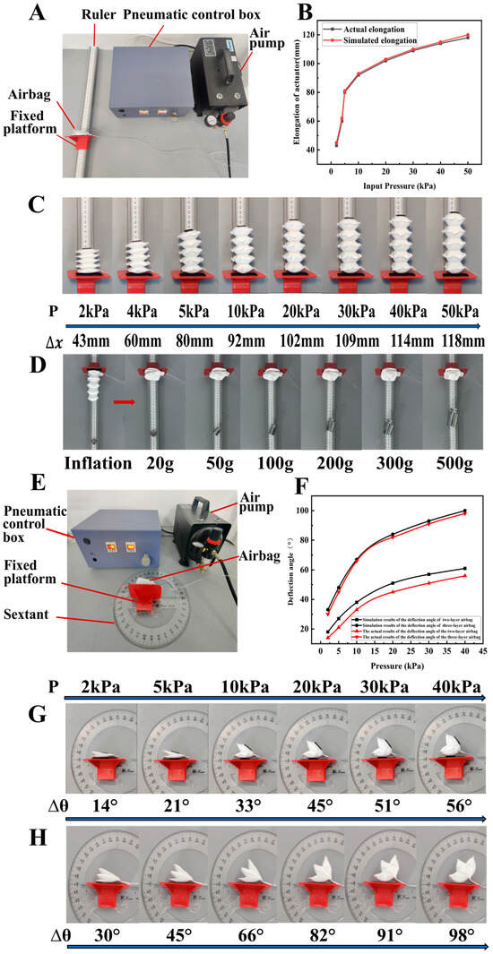
Figure 6.
The performance testing of thin-film elongation actuator and deflection actuator. (A,E) The testing platform. (B) The comparison curve of testing results and simulation. (C,G,H) The testing process. (D) The experimental study of horizontal plane contraction load capacity. (F) The comparison curve between test results and simulation.
3.2. Performance Testing of the Thin-Film Deflection Actuator
This article presents the results of performance tests on two-layer and three-layer thin-film deflection actuators, focusing on the actual deflection angle of the upper surface of the deflection actuators in comparison to the fixed base after pressurized expansion. A simple deflection angle testing platform was established (Figure 6E), consisting of the following components: (1) a fixed platform with Velcro on the contact surface for adhesive fixation of the deflection module; (2) a measuring instrument—a full-circle protractor; (3) a pneumatic control box used to regulate the input air pressure; and (4) an air pump to provide the air source. During the experiments, the input air pressure of the thin-film deflection actuator was sequentially increased from 2 kPa to 40 kPa (Figure 6F–H), and the deflection angles were recorded. The process was repeated ten times to obtain an average value. The experimental results indicate that, when the input air pressure ranges from 2 kPa to 40 kPa, the controllable deflection angle range of the two-layer deflection module is from 14° to 56°, while the controllable deflection angle range of the three-layer deflection module is from 30° to 98°. This range satisfies the movement requirements of most soft robots, with the deflection angle increasing as air pressure rises. The rate of increase in deflection angle decreases as air pressure increases. For instance, the deflection angle of the three-layer deflection module is approximately 30° at 2 kPa, about 45° at 5 kPa, and around 91° at 30 kPa. In contrast, the deflection angle of the two-layer deflection module is approximately 45° at 20 kPa. The deflection angle data obtained are typical for practical applications, providing experimental support for subsequent design combinations. The experiments show that the deflection behavior of the deflection module closely matches the simulation results in terms of expansion trend, shape, and deflection angle.
4. The Control System
This article presents a pneumatic control scheme designed to meet the demands of modular soft robotic systems with multi-module parallel movement, primarily consisting of two components: pneumatic actuation and hardware control, as illustrated in Figure 7A below.
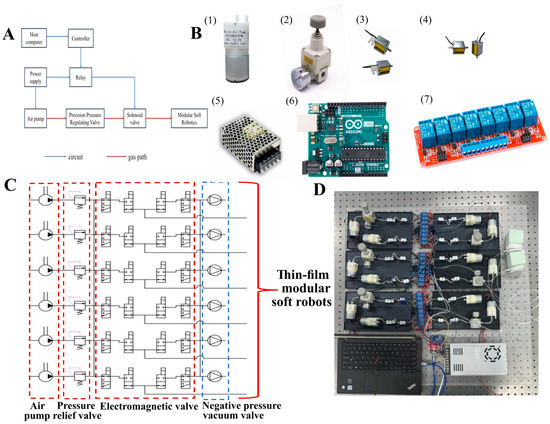
Figure 7.
The control system. (A) The pneumatic control system design scheme for modular soft robots. (B) The hardware components for the pneumatic control system of the modular soft robot: (1) the air pump; (2) the regulator; (3) the two-position three-way solenoid valve; (4) the two-position two-way solenoid valve; (5) the power supply; (6) the Arduino Uno development board; (7) the relay. (C) The pneumatic schematic diagram. (D) The control module object.
The hardware control section includes a power supply, microcontroller, relay, solenoid valve, and pressure sensor. Based on the predetermined program set by the upper computer, the microcontroller sends commands to the relay, which, upon receiving the signal, controls the switching of the solenoid valve, thereby regulating the motion state of each module in the thin-film modular soft robot. The constant-pressure driving air circuit is primarily composed of an air pump, precision pressure regulator, and solenoid valve. The air pump can provide either positive or negative pressure at a certain pressure level, which is then adjusted to the required driving air pressure for each module’s motion plan through the precision pressure regulator, while the solenoid valve controls whether to drive each module based on its switching state.
According to the pneumatic control principles described above, the hardware required for each complete pressure control air circuit (shown in Figure 7B) includes two micro-air pumps, one precision pressure regulating valve, two two-position two-way solenoid valves, and two two-position three-way solenoid valves. This air circuit configuration allows for positive pressure driving and negative pressure restoration of the thin-film modular soft robot actuators. Additionally, the hardware for the control circuit includes a DC power supply, a microcontroller board, and relays.
This article presents a physical model based on the drive control principles for modular soft robotics and the hardware selection described previously. Adhering to the concept of modularization, each complete air pathway is assembled as a movable and modular fixed unit, allowing each air pathway module to be arranged in parallel and independently set to different driving pressure levels. The number of modules can then be selected to connect circuits according to the needs of combinatorial experiments. Figure 7C,D illustrate the circuit design and physical representation of the pneumatic driving system for the thin-film modular soft robot.
5. Experimental Study of the Thin-Film Modular Soft Robots
5.1. Peristaltic Soft Robot Experiments
In this paper, two square connectors and three thin-film elongation actuators are used to design a soft-body robot mimicking earthworm peristalsis, as shown in Figure 8A below. The three thin-film elongation actuator modules are labeled M11, M12, and M13, in that order. First, the movement mode of peristalsis is studied, with the movement occurring on a rubberized floor. Each movement mode is repeated 10 times to obtain an average value for comparison. The following movement modes are compared (Figure 8B): (1) M11, M12, and M13 inflate and inhale simultaneously, moving approximately 15.4 mm per cycle; (2) M11 and M12 inflate → M11 and M12 inhale, followed by M13 inflating → M13 inhales, moving approximately 41.6 mm per cycle; (3) M11 inflates → M11 inhales, M12 and M13 inflate → M12 and M13 inhale, moving approximately 50.3 mm per cycle; (4) M11 inflates → M11 inhales, M12 inflates → M12 inhales, M13 inflates → M13 inhales, moving approximately 65.6 mm per cycle.
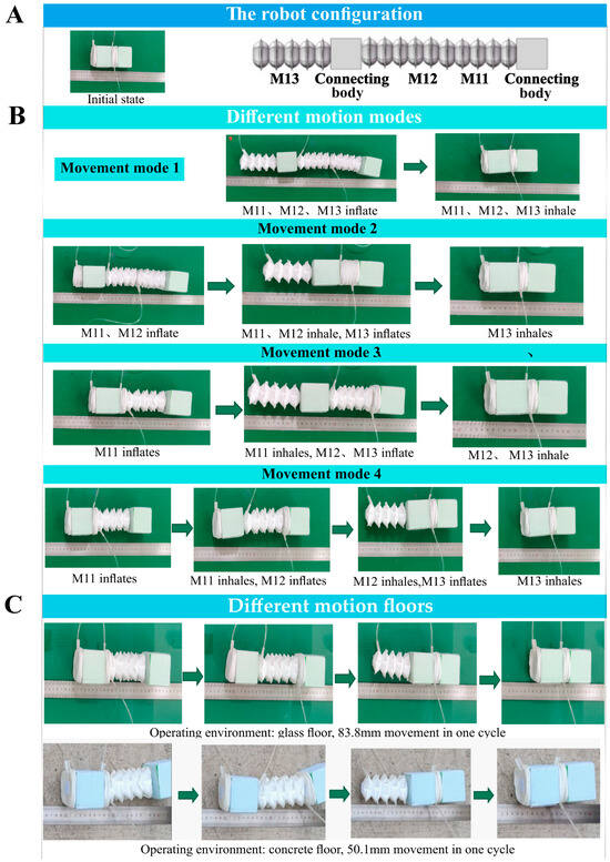
Figure 8.
The peristaltic soft robot experiments. (A) The robot configuration. (B) Different motion modes. (C) Different motion floors.
Using the displacement from the largest movement mode (Mode 4), peristaltic crawling experiments were conducted in different operating environments (Figure 8C). The same method was used to perform 10 cycles and calculate the average for comparison. The experimental results show that, when the peristaltic soft robot crawls on a glass surface, it moves approximately 83.8 mm per cycle. When tested on a cement surface, the movement was slightly different. The results suggest that, when the friction of the ground is lower, the peristaltic movement rate increases. However, this type of movement lacks a fixed module and is influenced by inertia, causing the elongation actuator’s forward motion to also produce a backward displacement, resulting in a relatively lower overall movement rate.
5.2. Obstacle Avoidance Experiments of the Planar Crawling Soft Robot
This paper utilizes 10 three-layer thin-film deflection actuators, two connection modules, and one thin-film elongation actuator to construct a planar crawling soft robot, as shown in Figure 9A(1). The robot is capable of performing various movement modes, such as straight movement, deflection avoidance, and obstacle climbing. The two ends of the robot consist of fixed modules, each constructed from one connection module and four deflection modules. During movement, the deflection structures on either side of the connection module expand and compress against the ground to increase friction. This allows one end of the modular planar crawling soft robot to be fixed in place, making its movement more controllable and efficient. The following describes the movement processes for several operation modes, with red representing the inflated state and blue representing the uninflated state.
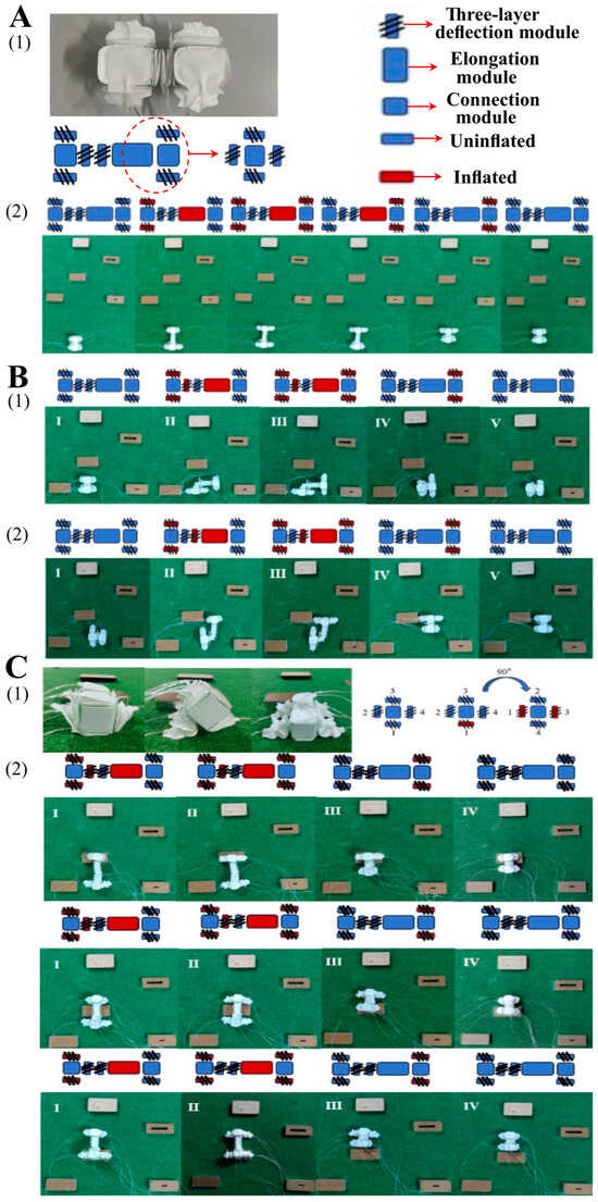
Figure 9.
The experiments related to the planar crawling soft robot. (A) The planar crawling soft robot experiments: (1) the module combination approach; (2) the straightforward motion steps. (B) The deflection and obstacle avoidance motion process of the planar crawling soft robot: (1) right turning motion; (2) left turning motion. (C) The obstacle-crossing process: (1) motion modal transformation; (2) the flowchart of the obstacle-crossing motion.
First, the robot performs planar straight motion (as shown in Figure 9A(2)), and each motion cycle consists of five steps: (1) apply 40 kPa of air pressure to the deflection modules on both sides of the rear fixed module and apply 50 kPa to the elongation module; (2) while maintaining the aforementioned air pressures, apply 40 kPa to the deflection modules on both sides of the front fixed module; (3) the deflection modules on both sides of the rear fixed module inhale; (4) the elongation module inhales; (5) the deflection modules on both sides of the front fixed module inhale. After one cycle, the modular soft robot moves approximately 110 mm in a straight line, with an average crawling speed of 55 mm/s. The robot then repeats this motion cycle until it encounters an obstacle. When faced with an obstacle, two movement modes are available: planar deflection obstacle avoidance and climbing over the obstacle.
As shown in Figure 9B, the robot performs an obstacle avoidance maneuver by deflection, starting with a right turn. This is completed in five steps: (1) apply 40 kPa to the deflection modules on both sides of the rear fixed module; (2) while maintaining the aforementioned air pressure, apply 30 kPa to the right-turn deflection module and 50 kPa to the elongation module; (3) while maintaining the air pressures, apply 40 kPa to the deflection modules on both sides of the front fixed module; (4) inhale the deflection modules on both sides of the rear fixed module, along with the right-turn deflection module and the elongation module; (5) the front fixed module inhales. A left turn is performed similarly, with adjustments made to the deflection modules receiving air pressure.
The modular soft robot designed in this paper can switch between motion modes, specifically between lateral and vertical deflection movements. When encountering obstacles, the robot can switch to an alternative movement modality to overcome them, in addition to traditional deflection movements for obstacle avoidance. As shown in Figure 9C(1), the robot’s fixed module is identified, with the first deflection module (Module 1) starting from the ground and numbered sequentially from 1 to 4 in a clockwise direction. When the first deflection modules of the front and rear fixed modules are inflated to 40 kPa simultaneously, the robot can rotate 90° along its horizontal central axis, changing its movement mode. Climbing and crawling movements are performed as shown in Figure 9C(2), consisting of four steps: (1) apply 40 kPa to the deflection modules on both sides of the rear fixed module, 30 kPa to the upward deflection module, and 50 kPa to the elongation module; (2) apply 40 kPa to the deflection modules on both sides of the front fixed module; (3) ensure the deflection modules on both sides of the rear fixed module, the upward deflection module, and the elongation module inhale; (4) the front fixed module inhales to return to the uninflated state. The above cycle is repeated once more, at which point the crawling soft robot begins its downward movement. Due to the influence of its own gravity, a natural descending motion is initiated. As a result, during the third cycle, only the elongation module requires a pressure of 50 kPa, while the deflection modules remain unpressurized. After completing these three cycles, the robot successfully climbs over an obstacle with a width of 80 mm and a height of 30 mm. This experiment demonstrates the application potential of modular soft robots in planar inspection and obstacle avoidance tasks, confirming their multifunctional performance.
6. Discussion
Regarding the issue of the relatively low overall movement rate of the peristaltic soft robot, we propose two possible solutions. Firstly, we could utilize anisotropic properties to inhibit backward sliding, such as a biomimetic structure where the front end is smooth and the rear end has barbed ring patterns, resembling an earthworm. Secondly, we could actively counter backward inertial forces through additional power, for example, by incorporating a lightweight mass block that can slide within the robot, controlled by micro-actuators. During the elongation phase, the mass block moves forward rapidly, creating a forward inertial force that counters the overall backward inertia of the body; during the contraction phase, the mass block returns to the rear without affecting the overall contraction. With respect to the obstacle avoidance capability of planar crawling robots, this modular soft robot is lightweight and compact, enabling it to maneuver in confined spaces while avoiding obstacles. Moreover, it can be assembled with various functional components to adapt to diverse environments. However, the complexity of its external pneumatic circuit somewhat limits the robot’s range of motion. Future developments may focus on optimizing the control system towards greater integration and wireless functionality.
7. Conclusions
This study proposes incorporating modular concepts and thin-film materials into soft robot design and realizing the robot’s peristalsis and obstacle avoidance functions through two thin-film actuators and connection modules. The use of highly flexible, lightweight, and stable TPU film materials in the manufacture of soft robotic actuators addresses the limitations of movement forms, poor durability, and instability commonly associated with silicone rubber-based soft robots. By employing modular design concepts, we simplify the development of two types of soft actuators for motion, creating combinations optimized for planar peristalsis and planar obstacle avoidance scenarios. Moreover, we have developed high-performance thin-film actuators produced with exceptional efficiency and precision. The elongation actuator reaches an extension length of 118 mm under 50 kPa of input pressure—approximately 59 times its original length—and is capable of pulling a 500 g load during horizontal contraction. The two-layer deflection actuator achieves a deflection angle of 56° at 40 kPa, while the three-layer version reaches up to 98°. The design of combination modules and driving strategies broadens the motion modalities and application scenarios of thin-film modular soft robots. Moreover, preliminary research on self-reconfiguration capabilities has improved operational efficiency and flexibility, providing valuable insights for the study of thin-film modular soft robots.
Supplementary Materials
The following supporting information can be downloaded at: https://www.mdpi.com/article/10.3390/act14090418/s1.
Author Contributions
Conceptualization, A.G.; methodology, A.G.; software, Z.J.; validation, A.G., Z.J. and G.J.; formal analysis, Z.J.; investigation and resources, S.Y., W.X. and X.H.; data curation, A.G.; writing—original draft preparation, A.G. and Z.J.; writing—review and editing, A.G. and Z.J.; visualization, Z.J.; supervision, G.J.; funding acquisition, G.J. All authors have read and agreed to the published version of the manuscript.
Funding
This work was supported by Key Project of the National Natural Science Foundation Joint Fund of China (Grant No. U22B2089). Date: January 2023–December 2026.
Data Availability Statement
The original contributions presented in this study are included in the article. Further inquiries can be directed to the corresponding author.
Conflicts of Interest
The authors declare no conflicts of interest.
Correction Statement
This article has been republished with a minor correction to the Data Availability Statement. This change does not affect the scientific content of the article.
References
- Marechal, L.; Balland, P.; Lindenroth, L.; Petrou, F.; Kontovounisios, C.; Bello, F. Toward a common framework and database of materials for soft robotics. Soft Robot. 2021, 8, 284–297. [Google Scholar] [CrossRef] [PubMed]
- Elango, N.; Faudzi, A.A.M. A review article: Investigations on soft materials for soft robot manipulations. Int. J. Adv. Manuf. Technol. 2015, 80, 1027–1037. [Google Scholar] [CrossRef]
- Whitesides, G.M. Soft robotics. Angew. Chem. Int. Ed. 2018, 57, 4258–4273. [Google Scholar] [CrossRef] [PubMed]
- Lee, C.; Kim, M.; Kim, Y.J.; Hong, N.; Ryu, S.; Kim, H.J.; Kim, S. Soft robot review. Int. J. Control Autom. Syst. 2017, 15, 3–15. [Google Scholar] [CrossRef]
- Ahmed, F.; Waqas, M.; Jawed, B.; Soomro, A.M.; Kumar, S.; Hina, A.; Khan, U.; Kim, K.H.; Choi, K.H. Decade of bio-inspired soft robots: A review. Smart Mater. Struct. 2022, 31, 073002. [Google Scholar] [CrossRef]
- Zaidi, S.; Maselli, M.; Laschi, C.; Cianchetti, M. Actuation technologies for soft robot grippers and manipulators: A review. Curr. Robot. Rep. 2021, 2, 355–369. [Google Scholar] [CrossRef]
- Shintake, J.; Cacucciolo, V.; Floreano, D.; Shea, H. Soft robotic grippers. Adv. Mater. 2018, 30, e1707035. [Google Scholar] [CrossRef] [PubMed]
- Tauber, F.; Desmulliez, M.; Piccin, O.; Stokes, A.A. Perspective for soft robotics: The field’s past and future. Bioinspir. Biomim. 2023, 18, 035001. [Google Scholar] [CrossRef] [PubMed]
- Shi, Y.; Dong, W.; Lin, W.; Gao, Y. Soft wearable robots: Development status and technical challenges. Sensors 2022, 22, 7584. [Google Scholar] [CrossRef] [PubMed]
- Li, J.; Wu, S.; Zhang, W.; Ma, K.; Jin, G. 3D Printing of Silicone Elastomers for Soft Actuators. Actuators 2022, 11, 200. [Google Scholar] [CrossRef]
- Yang, H.D.; Asbeck, A.T. A layered manufacturing approach for soft and soft-rigid hybrid robots. Soft Robot. 2020, 7, 218–232. [Google Scholar] [CrossRef] [PubMed]
- Natividad, R.; Del Rosario, M.; Chen, P.C.Y.; Yeow, C.-H. A reconfigurable pneumatic bending actuator with replaceable inflation modules. Soft Robot. 2018, 5, 304–317. [Google Scholar] [CrossRef] [PubMed]
- Yang, D.; Feng, M.; Gu, G. High-stroke, high-output force, fabric-lattice artificial muscles for soft robots. Adv. Mater. 2024, 36, 2306928. [Google Scholar] [CrossRef] [PubMed]
- Yu, M.; Yang, W.; Yu, Y.; Cheng, X.; Jiao, Z. A crawling soft robot driven by pneumatic foldable actuators based on Miura-Ori. Actuators 2020, 9, 26. [Google Scholar] [CrossRef]
- Kim, W.; Byun, J.; Kim, J.K.; Choi, W.Y.; Jakobsen, K.; Jakobsen, J.; Lee, D.Y.; Cho, K.J. Bioinspired dual-morphing stretchable origami. Sci. Robot. 2019, 4, eaay3493. [Google Scholar] [CrossRef]
- Ma, J.; Chai, S.; Chen, Y. Geometric design, deformation mode, and energy absorption of patterned thin-walled structures. Mech. Mater. 2022, 168, 104269. [Google Scholar] [CrossRef]
- Cui, J.; Poblete, F.R.; Zhu, Y. Origami/Kirigami-guided morphing of composite sheets. Adv. Funct. Mater. 2018, 28, 1802768. [Google Scholar] [CrossRef]
- Feng, F.; Plucinsky, P.; James, R.D. Helical Miura origami. Phys. Rev. E 2020, 101, 033002. [Google Scholar] [CrossRef] [PubMed]
- Wang, Y.; Pang, S.; Jin, H.; Xu, M.; Sun, S.; Li, W.; Zhang, S. Development of a biomimetic scallop robot capable of jet propulsion. Bioinspir. Biomim. 2020, 15, 036008. [Google Scholar] [CrossRef]
Disclaimer/Publisher’s Note: The statements, opinions and data contained in all publications are solely those of the individual author(s) and contributor(s) and not of MDPI and/or the editor(s). MDPI and/or the editor(s) disclaim responsibility for any injury to people or property resulting from any ideas, methods, instructions or products referred to in the content. |
© 2025 by the authors. Licensee MDPI, Basel, Switzerland. This article is an open access article distributed under the terms and conditions of the Creative Commons Attribution (CC BY) license (https://creativecommons.org/licenses/by/4.0/).