1. Introduction
Two-axis coupled electromechanical actuation systems (TCEAS) have become indispensable components in a wide range of industrial applications, including aerospace, robotics, and weapon aiming [
1,
2,
3]. These systems are responsible for precisely controlling the bidirectional movement and positioning of mechanical components, which directly impacts the overall performance and efficiency of the equipment. For instance, in aerospace applications, accurate control of two-axis actuators ensures the stable operation of aircraft control surfaces and satellite pointing mechanisms [
4]; in robotics, they enable robots to perform complex tasks with high precision [
5]; in weapon aiming, they can ensure that the firing system maintains precise aiming in terms of orientation and pitch during movement [
6]. However, the performance of TCEAS is significantly compromised by several challenges. Complex nonlinear friction within the system, such as static friction, coulomb friction, and viscous friction, leads to tracking errors, limit cycles, and even system instability [
7]. Parameter uncertainties, arising from manufacturing tolerances, component wear, and environmental changes, further degrade the control accuracy [
8]. Additionally, the strong coupling effects between the two axes lead to the relative complexity of achieving excellent robust control of each axis, posing a significant obstacle to realizing high-performance tracking [
9].
Over the years, numerous control strategies have been proposed to address these issues. Traditional control methods, such as PID control, have been extensively applied because of their simplicity and ease of implementation [
10]. However, PID controllers often struggle to handle complex nonlinearities and uncertainties, resulting in limited control performance. Advanced control techniques, including sliding mode control [
11], backstepping control [
12], and model predictive control [
13], have shown better adaptability to nonlinear systems. Sliding mode control drives motion trajectory for electromechanical actuation systems to the predetermined sliding surface and keeps it stable. It is used to enhance the robustness, enabling accurate tracking of the given expected motion trajectory even when confronted with external force impacts or load changes [
14]. However, sliding mode control not only creates unwanted vibrations, but also causes wear and tear on mechanical components such as gears and bearings. This can reduce the life of the equipment and introduce additional errors in the control system that can affect overall performance and stability. Backstepping control decomposes a complex nonlinear system into a series of simpler subsystems and designs Lyapunov functions for each subsystem, guaranteeing overall stability. In the control of multi-axis servo systems, backstepping control has been successfully used to achieve coordinated control of multiple axes [
15]. However, as the complexity and order of the system increase, the design process of backstepping control becomes extremely tedious. The design of the controller is both time-consuming and error-prone due to the need to design multiple Lyapunov functions with an ever-increasing number of intermediate variables and computations. Model predictive control predicts the behavior of the controlled object in future finite time domain by solving an optimization problem at each sampling moment [
16]. The electromechanical actuation system based on two-axis coupling achieves better tracking performance by optimizing future control actions [
17]. However, its control performance depends on the accuracy of the system model. An inaccurate model may lead to poor control effects. In practical engineering, uncertain factors such as nonlinear friction, component wear, and unmodeled dynamics can all affect the modeling of the system.
Furthermore, in the context of developing various high-performance control strategies, many researchers are dedicated to using friction models to suppress the influence of friction nonlinearity in electromechanical actuation systems [
18,
19], thereby enhancing the controllability effect. Some studies have employed the Dahl friction model [
20], LuGre friction model [
21], and Stribeck friction model [
22] to describe the friction behavior. Although these models can capture certain characteristics of friction, they may not fully represent the complex friction phenomena in TCEAS. Moreover, most existing control methods either focus on single-axis control or do not adequately consider the strong coupling effects between the two axes, limiting their effectiveness in practical TCEAS.
To bridge these gaps, this paper proposes an adaptive robust stable tracking control (ARSTC) method with friction compensation for TCEAS. We make the following contributions: (1) The smoothness property of the hyperbolic tangent function is employed to construct a continuously differentiable friction dynamic function to improve the characterization of friction nonlinearity. Unlike the LuGre model, which introduces internal state variables that complicate multi-axis extension, the proposed hyperbolic tangent-based model avoids such complexity while retaining key friction characteristics. (2) A mathematical dynamic model of the TCEAS considering friction nonlinearity and model uncertainty is established, providing a more realistic basis for controller design. (3) Unlike prior work, our method explicitly distinguishes adaptive and robust roles: adaptation mitigates parametric uncertainties, while robustness handles unmodeled dynamics. The value of the presented method has been rigorously validated through stability analysis and extensive comparisons of co-simulations.
Furthermore, the proposed method is not a simple extension of single-axis control. For a two-axis coupled system, it combines the coupling dynamic model of the mechanical interaction between the two axes and the cross-axis friction effect. This model is based on multi-body system dynamics rather than a simplified derivation based on a single-axis. Through a unified adaptive robust framework, it is used to estimate the coupling friction parameters and suppress the cross-axis interference, thereby solving the problem of mutual interference between the axes. Finally, the stability analysis of the coupled closed-loop system is conducted to ensure that all signals are bounded under the interaction of the two axes. These contributions are unique to TCEAS and cannot be reduced to the results of a single-axis.
The remainder of this paper is organized as follows:
Section 2 develops the complete dynamic model of the electromechanical actuation system, including electrical and mechanical subsystems with friction effects.
Section 3 presents the adaptive robust controller design with stability proofs.
Section 4 details the co-simulation results and comparative analyses.
Section 5 discusses practical implications and concludes with future research directions.
3. Adaptive Robust Stable Tracking Controller Design
This section first establishes the control objectives, then develops the parameter adaptation mechanism, followed by the complete controller design and stability analysis.
3.1. Control Objectives
The design objective of the controller for the TCEAS is as follows: Given the system reference motion angle signal qd(t) = x1d(t) = [x1dh(t), x1da(t)]T, we design a bounded control input u = [uh, ua]T. We therefore make the attitude output of the system x1 = [x1h, x1a]T = [qh, qa]T track the reference motion angle signal of the TCEAS as accurately as possible.
To successfully design the proposed control strategy, necessary assumptions consistent with engineering realities are demonstrated in advance.
Assumption 1. The given angular command x1d(t) = [x1dh(t), x1da(t)]T of the TCEAS satisfies x1dh(t) ∈ C3, x1da(t) ∈ C3.
Assumption 2. The upper and lower thresholds of unknown parameter of the TCEAS is known, i.e., , in which , .
Assumption 3. The magnitude and range of the unmodeled disturbance D(t) of the two-axis coupled electromechanical actuation system is known, i.e., , , in which , , and are known positive numbers.
3.2. Parameter Adaptive Control Mechanism
The
and
are set as the estimated values of the unknown friction coefficients
and
in the TCEAS, and let
and
denote the estimated errors of uncertain parameters. To achieve effective convergence of the subsequently derived parameter adaptive functions, the following discontinuous mapping mechanism equation is given [
25]:
where
denotes the maximum value of
and
denotes the minimum value of
, we have
j = 1, 2,
i = 1, 2, 3. The following controlled parameter adaptive law is used:
where
,
is a positive definite diagonal matrix which is the control gain matrix of the parameter adaptive function, and
is the parameter adaptive function.
Based on the above action of the discontinuous parameter adaptive mechanism, we have the following lemma: for any adaptive function
derived, it possesses the following mathematical properties [
25]:
In summary, the discontinuous mapping adaptive law (31) ensures parameter estimates are bounded within and avoid divergence. For coupled systems like TCEAS, due to cross-axis interactions and disturbances, estimates do not strictly converge to true values but stabilize in an effective range that supports friction compensation—this is sufficient to guarantee the controller’s performance.
3.3. Controller Design
Aiming at the friction nonlinearity, parameter uncertainty, and unmodeled disturbance existing in the TCEAS, the design of an ARSTC strategy is carried out.
First, the error variable function is characterized as follows:
where
z1 = [
z1h,
z1a]
T denotes the tracking error of the TCEAS, which is obtained by taking the derivative of time with respect to
z1:
Next, by characterizing
to represent the deviation between them, where
represents virtual control function for state
x2, the following is designed:
where
k1 = diag{
k1h,
k1a} is the non-negative control gain matrix. Thus, the derivative for
z1 is as follows:
It can be analyzed from (37) that the transfer function matrices , , and , are all asymptotically stable systems. When and approach zero, according to the stability theory, it can be concluded that and must also converge to zero. Further analysis shows that the transfer functions and simultaneously contain the position tracking error vector and the velocity tracking error vector, which are nonlinear mapping functions containing errors and their derivatives. If the control strategy design can ensure that and , then according to the Lyapunov stability theory, it can be deduced that the position error and velocity error tend to zero, thereby achieving the optimization of the system tracking performance.
Based on the above analysis, the subsequent controller design will take the asymptotic convergence of and as the core optimization objective, and achieve the dynamic global exponential stability of errors by constructing an adaptive robust control law.
From (30) and equation
, the following can be obtained:
Analyzing the structure of (38), we can design the ARSTC input
u for the TCEAS as follows:
where
k2 = diag{
k2h,
k2a} is the positive feedback control gain matrix,
um = [
umh,
uma]
T is the parametric adaptive model feedforward compensation control law to enhance the stability of the two-axis coupled system,
us refers to the robust control term for a two-axis coupled system,
us1 = [
us1h,
us1a]
T stands for the linear robust term, and
us2 = [
us2h,
us2a]
T stands for the nonlinear robust term used to suppress system uncertainty and unmodeled disturbances.
Substituting (39) into (38) yields the following:
In order to further improve the stability of the TCEAS,
us2 is designed to satisfy the following calming conditions:
where
ε1 denotes a positive adjustable value which is capable of being sufficiently small.
Therefore,
us2 can be designed as follows:
where the definition of Ψ
1 satisfies
,
,
k2s2 = diag{
k2sh,
k2sa} is the positive feedback nonlinear control gain matrix.
3.4. Performance Theorem and Stability Analysis
Theorem 1. By using the discontinuous mapping adaptive law (31), design an adaptive function and select sufficiently large feedback gains k1 and k2 to make the matrix Λ1, defined below as a positive definite matrix:
Then the presented ARSTC controller (39) from the TCEAS can be guaranteed to have the following performance: all signals in the closed-loop controller are bounded and defined as the following Lyapunov function:
this satisfies the following inequality:
where
,
is the minimum eigenvalue of the positive definite matrix.
Specific Proof Process: By combining (37) and (40), the derivative of
V1 can be obtained:
From (41) and (43), we have the following:
where
. Since the matrix is positively definite and combined with the definition of
, we can obtain the following:
By using the principle of contrast [
26], the following can be obtained:
Analyzing (49) shows that V1 is globally bounded, i.e., both and are bounded. Because the expected angle, angular velocity, and angular acceleration of the TCEAS are all bounded, , , , are also bounded. Combined with (33), the parameter estimation of the TCEAS is bounded, then um and us1 are bounded. Since is bounded, us2 is bounded, and ultimately the control input u of the design is known to be bounded. This completes the proof of Theorem 1.
Theorem 2. The TCEAS contains only parameter uncertainties, i.e., the unmodeled disturbance . The proposed control strategy not only yields the conclusion of Theorem 1, but also achieves the asymptotically stable tracking performance of the TCEAS, i.e., for .
Specific Proof Process: When the TCEAS only has parameter uncertainty, the following Lyapunov function is defined:
Combining (32), (37), (40) and the adaptive function
, the derivative of
V2 can be obtained:
It can be further obtained that
where
, which in combination with the designed ARSTC controller ensures that all signals of the TCEAS are bounded, it can be deduced that
. Therefore,
H is consistently continuous, according to Barbalat’s lemma [
27]; when time
, we have
. Furthermore, the characteristic of
when
is achieved, and the asymptotic control effect of the TCEAS is obtained. At this point, the derivation of Theorem 2 has been concluded.
4. Comparative Co-Simulation Numerical Calculations
In order to comprehensively verify the effectiveness of the nonlinear ARSTC strategy designed in this paper for a two-axis coupled electromechanical actuation system, an interface between RecurDyn and Matlab/Simulink is applied to realize the data exchange in the control system and two-axis coupled mechanical system to achieve the co-simulation numerical calculation. The mathematical equation of the controller and the motor system are established in Matlab/Simulink software, and the angular displacement and angular velocity from horizontal subsystem and vertical subsystem are read in real time through RecurDyn software, which are fed back to the Matlab/Simulink software to solve the output torque of the motor under the current state to drive the multi-body system model in RecurDyn software. The co-simulation principle of the TCEAS is shown in
Figure 3 [
28].
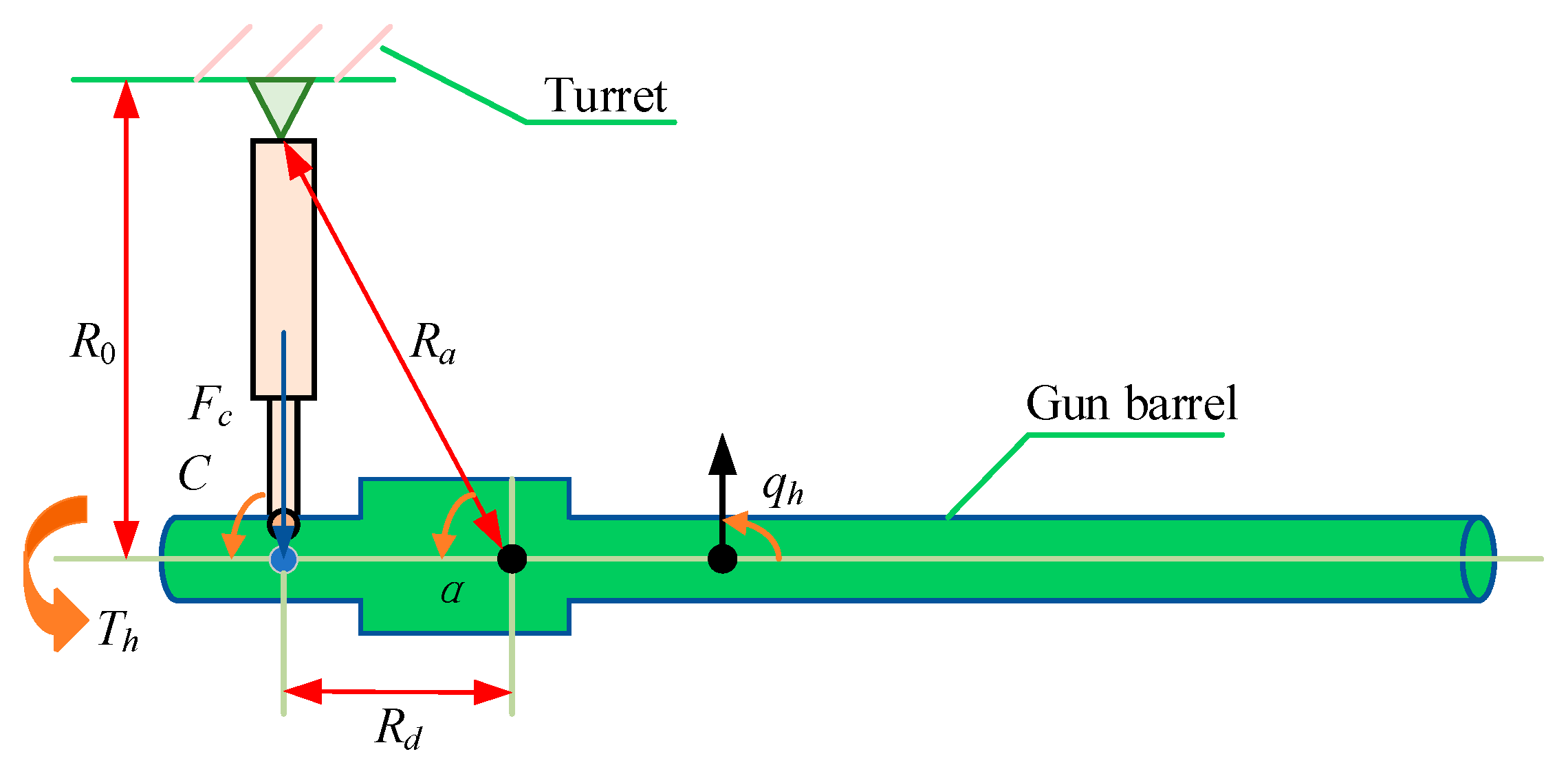
The following system parameters are set for the co-simulation numerical computation process: mh = 2100.00 kg, Lh = 5.15 m, g = 9.80 m/s2, ma = 5200.00 kg, La = 1.15 m, Jc = 0.0505 kg·m2, Jc,d = 0.0131 kg·m2, Bc = 0.0176 N·m·s/rad, Bc,d = 0.0066 N·m·s/rad, Kc = 3.75 N·m/V, Nc = 3, Lc = 0.02 m, Ra = 0.55 m, Rd = 0.44 m, R0 = 0.33 m, η = 0.8, α0 = arcsin(0.65), Js = 0.022 kg·m2, Bs = 0.0088 N·m·s/rad, Ns = 16, Ks = 3.35 N·m/V, Ks,e = 1.81 A·s/rad.
The friction parameters of the vertical subsystem in the co-simulation are set as fs1h = 42, fs2h = 110, fs3h = 0.5, fc1h = 23, fc2h = 30, and fb1h = 12, and the friction parameters of the horizontal subsystem in the co-simulation are set as fs1a = 90, fs2a = 300, fs3a = 85, fc1a = 20, fc2a = 160, and fb1a = 20. The friction parameters are determined based on two considerations: (1) Typical ranges of friction coefficients for electromechanical transmission systems (e.g., ball screws and servo motors) in engineering practice, where static friction-related parameters (e.g., fs1h, fs1a) are set to larger values to reflect the initial motion resistance, and viscous friction parameters (e.g., fb1h, fb1a) are calibrated to match the velocity-dependent damping characteristics of the transmission components; (2) Consistency with the continuously differentiable friction model structure (Equations (13) and (20)), where parameters such as fs2h, fs3h (vertical subsystem) and fs2a, fs3a = (horizontal subsystem) are adjusted to simulate the Stribeck effect, ensuring the model captures the transition from static to dynamic friction. These values are validated to induce noticeable friction nonlinearity in the system, which is necessary to test the compensation effectiveness of the ARSTC controller.
In addition, the harmonic superposition method is used to construct a stochastic road surface model as a disturbance to join the co-simulation process in this paper. The simulation adopts the Class E pavement excitation model referenced in [
23], which is a typical severe road condition with irregular bumps and vibrations. The driving speed is set to 30 km/h to simulate the dynamic disturbances transmitted to the TCEAS during vehicle movement. The magnitudes of these interferences ensure good consistency with engineering practice. We calibrate the interference range to match the measurement data of the on-board electromechanical system under Class E road conditions, ensuring that the interference can represent the real working environment.
The following three controllers are selected for comparison and validation by the co-simulation process.
- (1)
ARSTC: This is an adaptive robust stable tracking controller that considers the friction compensation proposed in this paper. The controller parameters are chosen as k1h = 5000, k2h = 1000, and k2sh = 1200 for the vertical subsystem and k1a = 8500, k2a = 1600, and k2sa = 2000 for the horizontal subsystem. The unknown parameter ranges of the system are θmax = [500, 200, 200, 1000, 500, 500]T, θmin = [0, 0, 0, 0, 0, 0, 0]T, and the parameter adaptive gain matrix Γ = diag{60, 0.5, 1.5, 110, 6.6, 4}.
- (2)
ARSC: This is an adaptive robust stable tracking controller without a friction compensation term. The comparison with this controller can verify the effectiveness of the continuous friction model in the ARSTC controller in compensating the friction nonlinearity of the two-axis coupled electromechanical actuation system. To ensure the fairness of the comparison, the parameters of this controller are consistent with the ARSTC controller.
- (3)
ARC: This is a general adaptive controller that does not take into account the role of the nonlinear robust control law, i.e., the parameters k2sh and k2sa are set to zero. The strong robustness of the nonlinear robust control law in the ARSTC controller can be verified by comparison with this controller. To ensure the fairness of the comparison, the rest of the control gains are consistent with the ARSTC controller.
The same gain setting ensures a fair comparison of control structures, and theoretical analysis of gain adjustments confirms the following: ARSC and ARC cannot achieve superior performance by simply increasing gains due to chattering and stability risks. ARSTC’s advantages stem from its integrated adaptive-friction and cross-coupling compensation, not gain tuning—strengthening the validity of its core contributions.
To quantitatively assess the tracking effectiveness of three controllers for the TCEAS, the statistical characteristic parameters of the tracking error are used as the evaluation indexes: the maximum value of the absolute value of the tracking error, Me, is selected to represent the deviation limit of the system under the extreme working conditions, the average value, Ae, reflects the average level of the overall tracking accuracy, and the standard deviation, Se, quantifies the degree of dispersion of the error sequence in order to measure the control stability.
Remark 1. To guarantee the effective use of the ARSTC controller in TCEAS, there are two methods that can usually be applied to determine the values of the design control parameters. The first approach is to mathematically compute the k1, k2, and k2s values such that the matrix Λ defined by (43) is a positive definite. Although this method is relatively rigorous, it suffers from additional cumbersome mathematical derivations that greatly increase the complexity of control parameter adjustment. This leads to limitations in engineering applications. For an alternative, a practicable method is to directly select larger values of k1, k2, and k2s without considering specific prerequisites. In our manuscript, we adopt the second method, which is convenient for online adjustment of control gain and requires less offline work. In the co-simulation, the control gains k1, k2, and k2s were carefully and cautiously adjusted, and then k1, k2, and k2s were gradually increased to ensure that the TCEAS obtains better stability performance; finally, the value of k1, k2, and k2s were appropriately increased to obtain the most satisfactory control effect.
4.1. Positioning Angle Signal Tracking
Given the reference motion angle signal of the vertical subsystem
, the reference motion angle signal of the horizontal subsystem
, the simulation time is set to 10 s. This desired tracking signal is able to check the steady state control quality and the positioning accuracy for TCEAS.
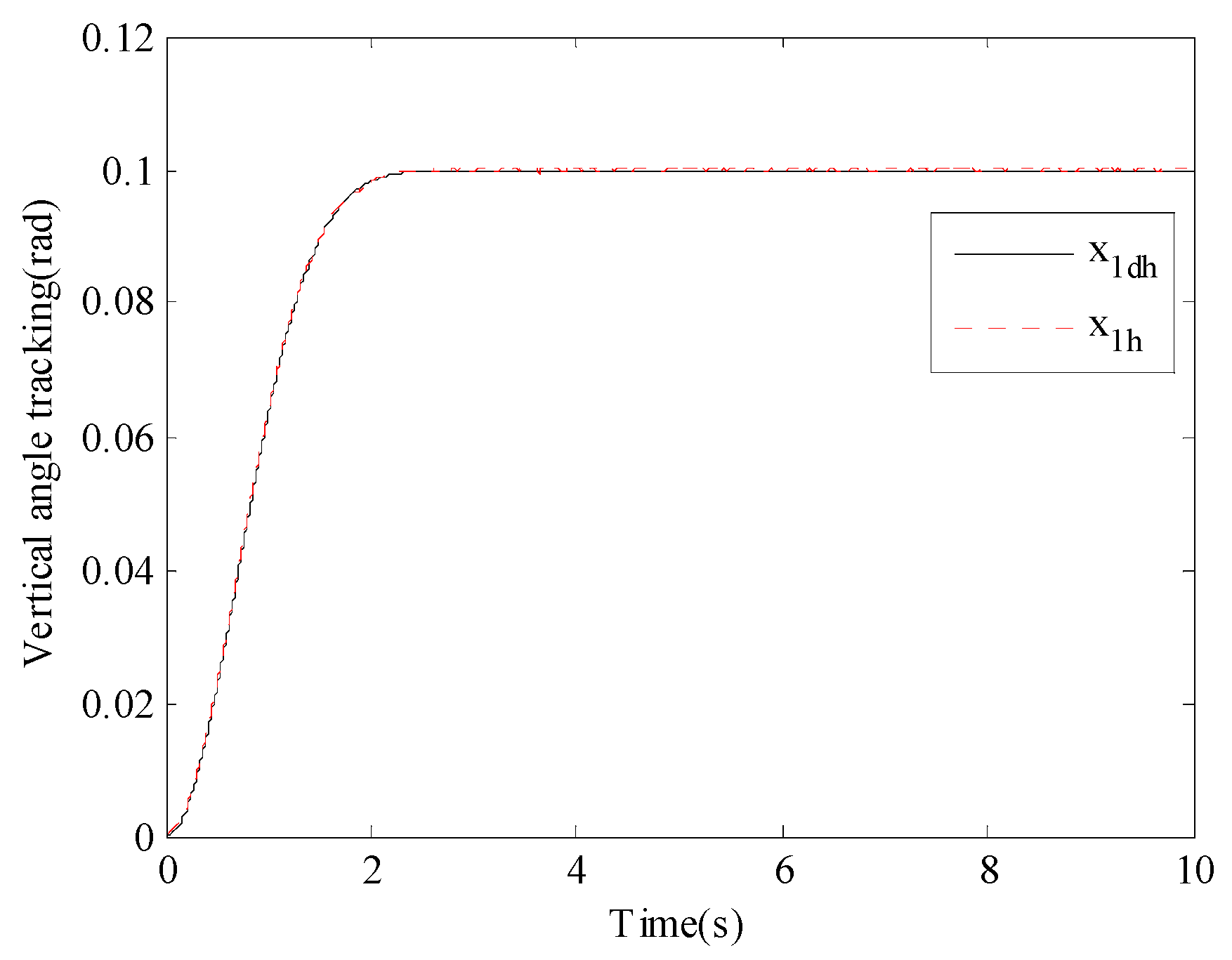
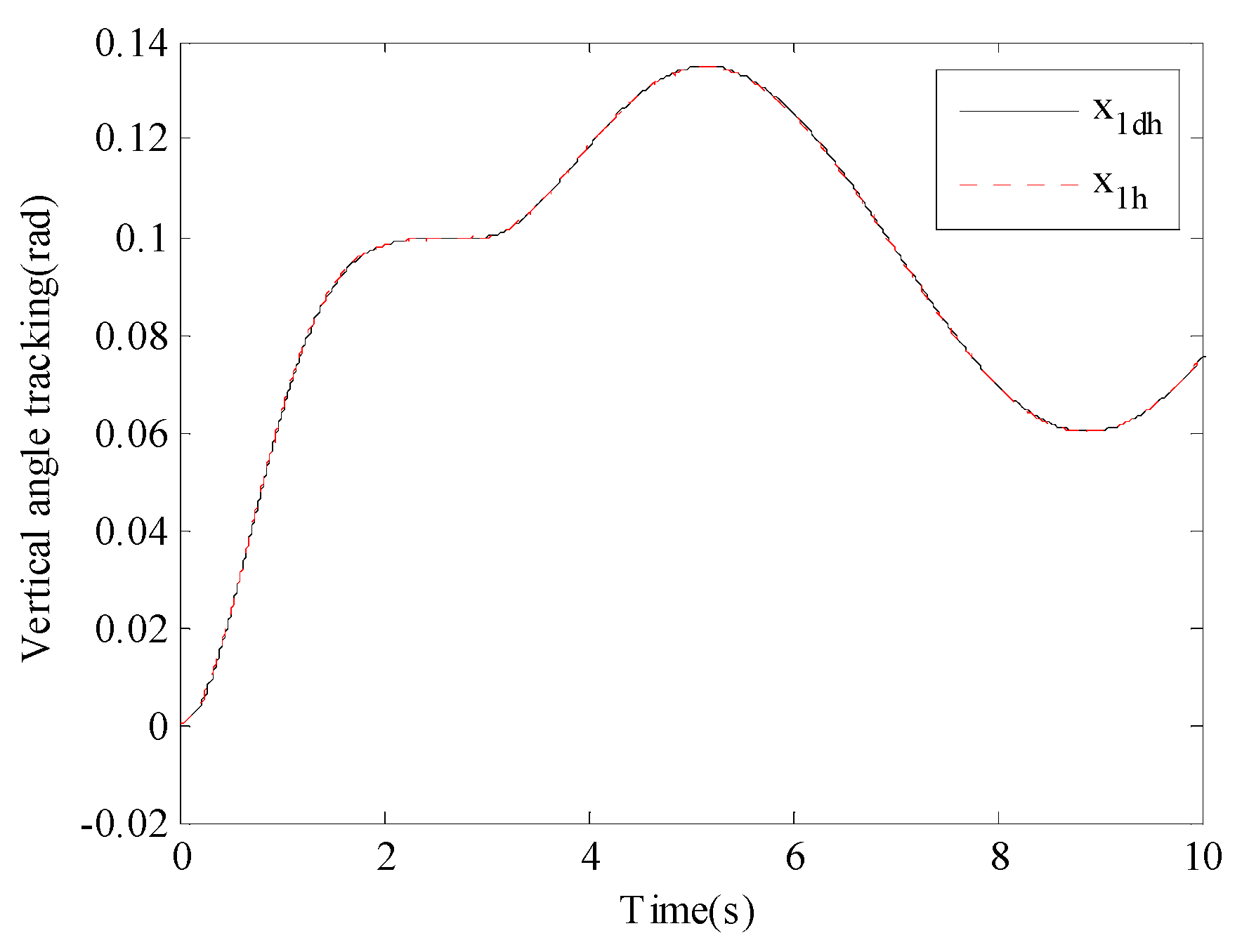
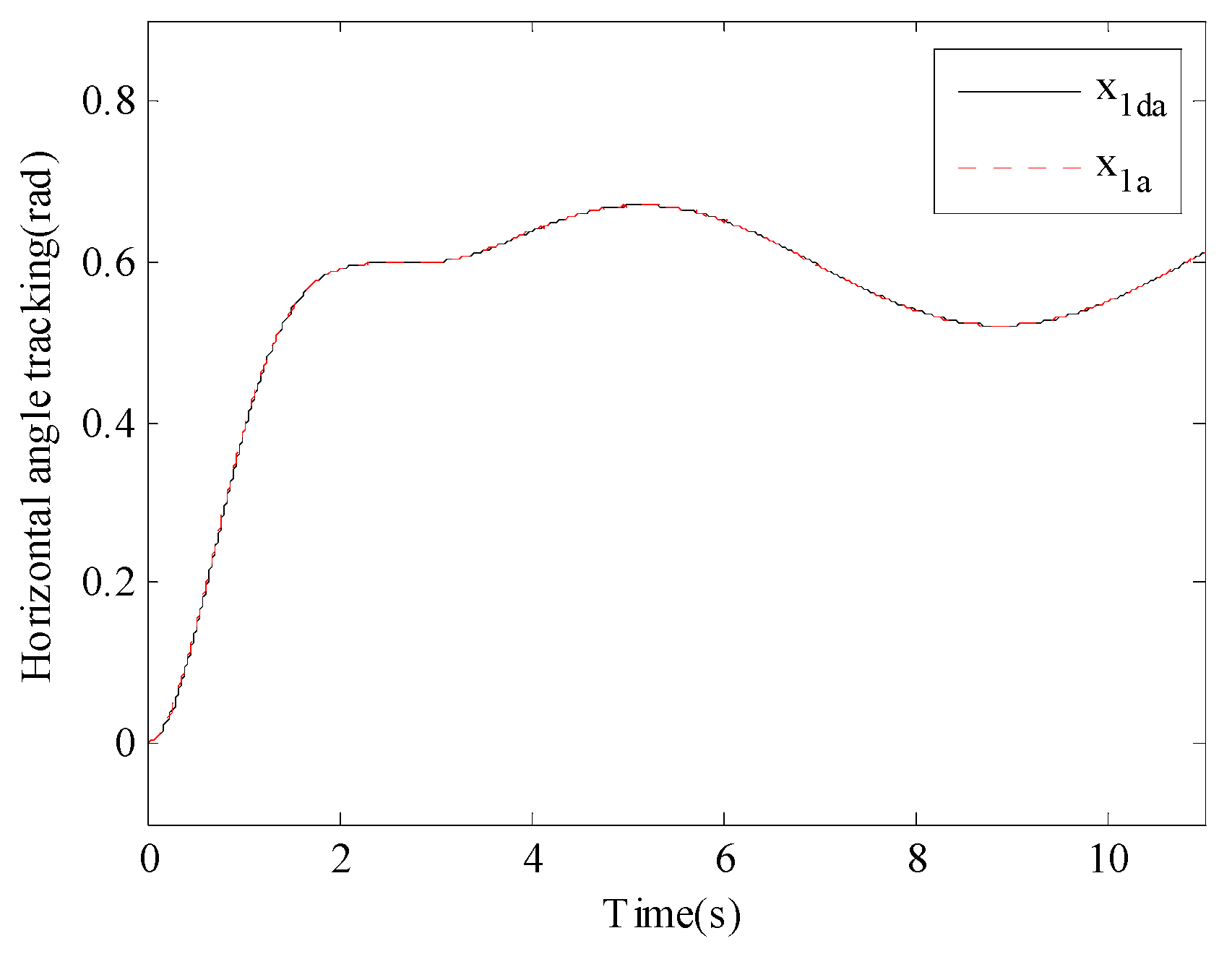
Figure 4 and
Figure 5 show the tracking process of the actual motion angle of the TCEAS to the reference motion angle command under the action of the ARSTC controller. The numerical calculation results show that the coincidence degrees of the tracking trajectories of the vertical subsystem and the horizontal subsystem with the reference curves both exceed 95%, verifying the superiority of the presented controller.
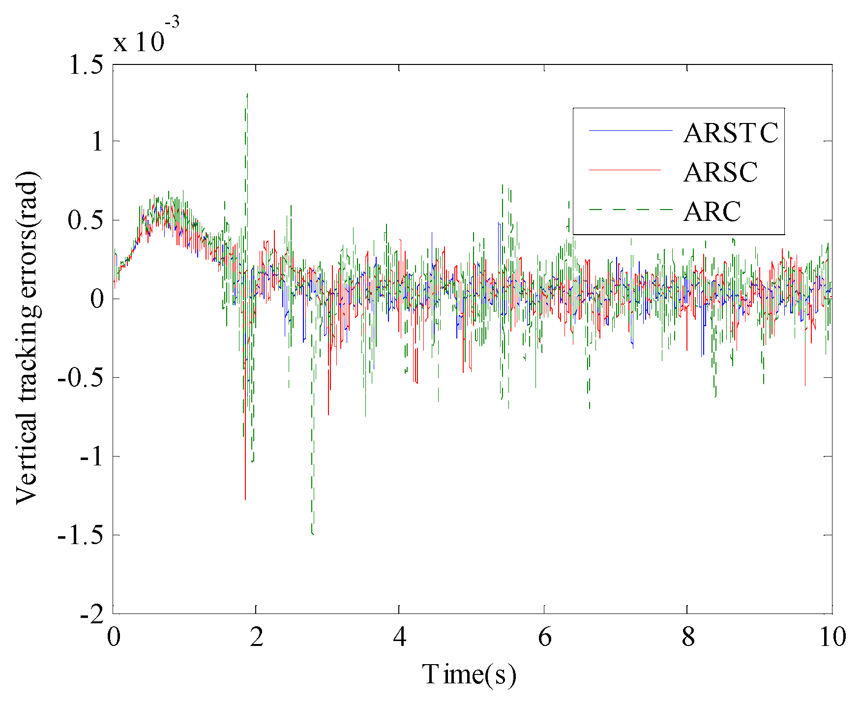
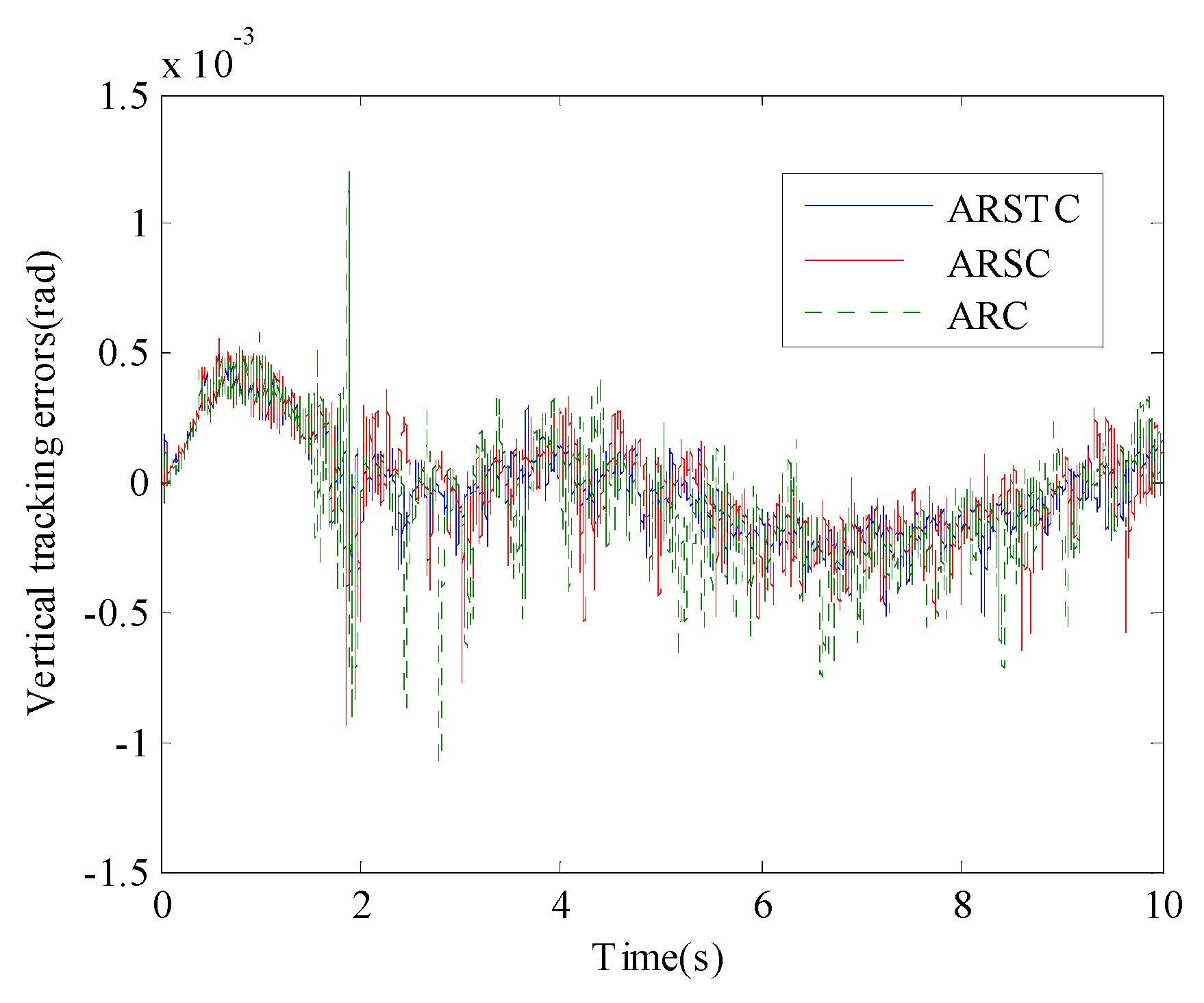
Figure 6 presents the comparison curves of tracking errors of the vertical subsystem under the three controllers of ARSTC, ARSC, and ARC. Even on the E-class road surface at 30 km/h, all three controllers can maintain the stability of the vertical subsystem. The positioning accuracy of the ARSTC controller for the vertical subsystem is better than that of the ARSC and ARC controllers because the ARSTC controller compensates for the unconsidered system friction by means of a smooth friction model in combination with an adaptive method, which greatly reduces the effect of friction nonlinearity and model uncertainty. Meanwhile, comparing with
Table 1, it can also be further found that the positioning accuracy of ARSTC is better than that of ARSC and ARC, which reflects the superiority of feed-forward compensation of friction characteristics and robust suppression of uncertainty.
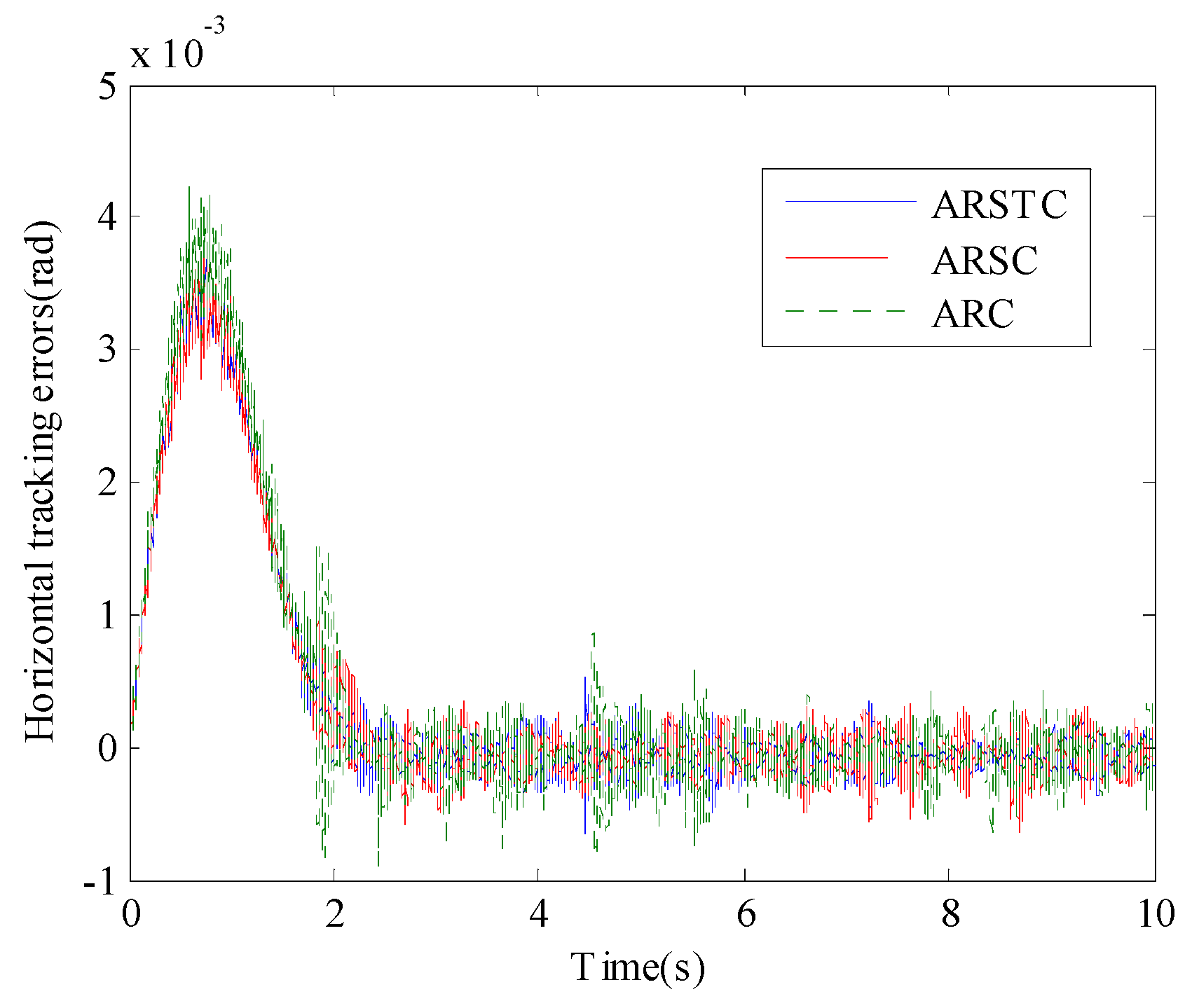
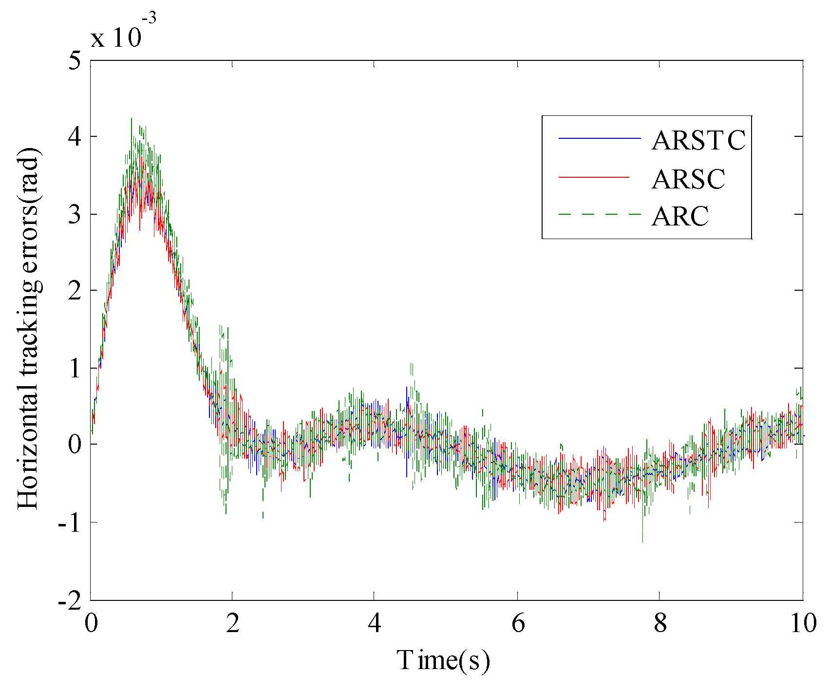
Figure 7 shows the comparative tracking error curves of the horizontal subsystem under the action of the three controllers ARSTC, ARSC, and ARC, and
Table 2 presents the steady-state performance indicators of the three controllers. The ARSTC control method also ensures that the horizontal subsystem achieves the best control result, once again demonstrating the feasibility of friction compensation and adaptive robust stable tracking control. Based on the current working conditions, although the external disturbances are intense, the proposed ARSTC controller can ensure the high-precision angular positioning of the TCEAS.
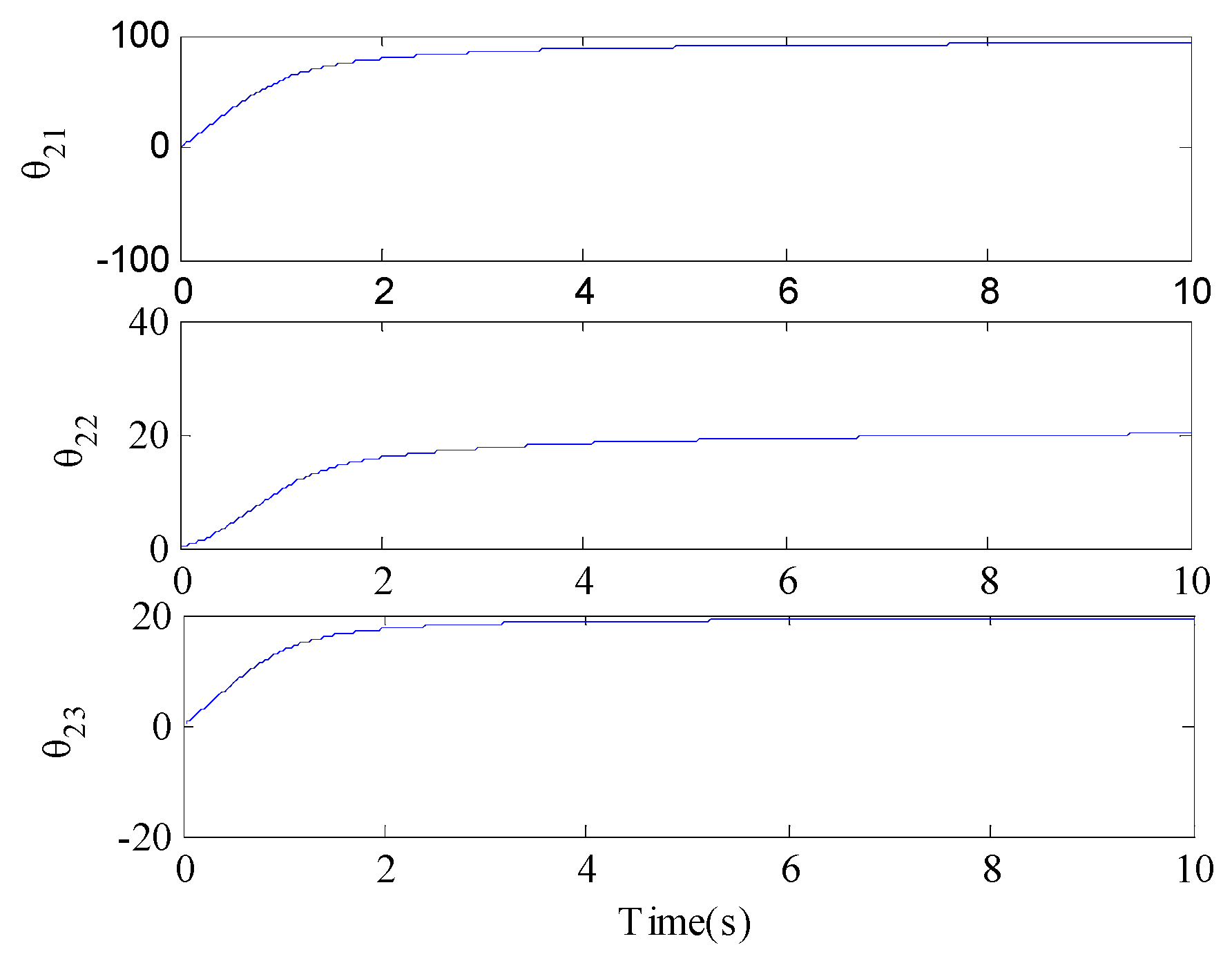
The parameter adaptive curves of the TCEAS under the action of the ARSTC controller are shown in
Figure 8 and
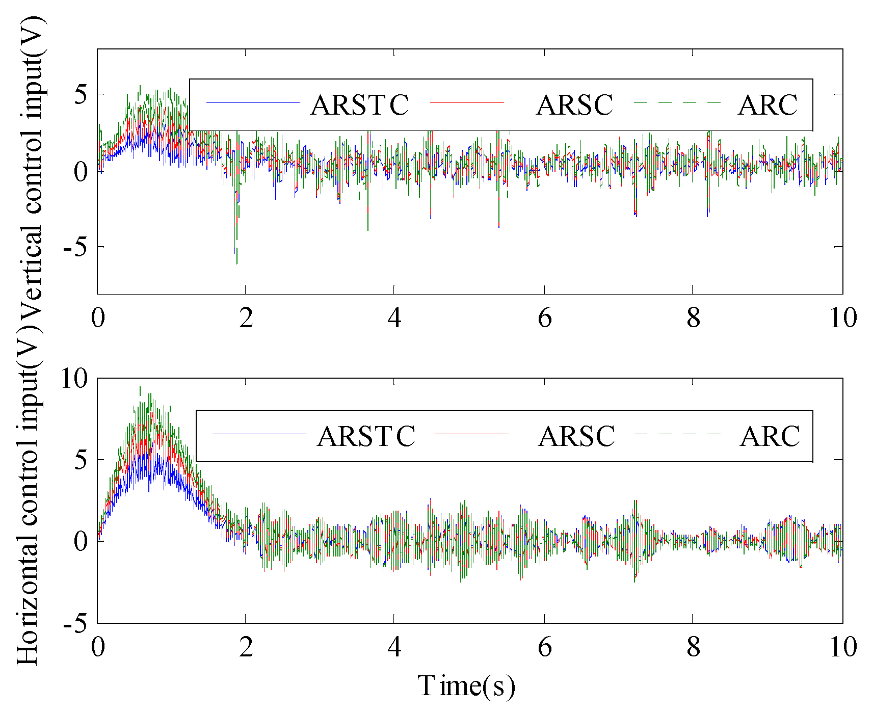
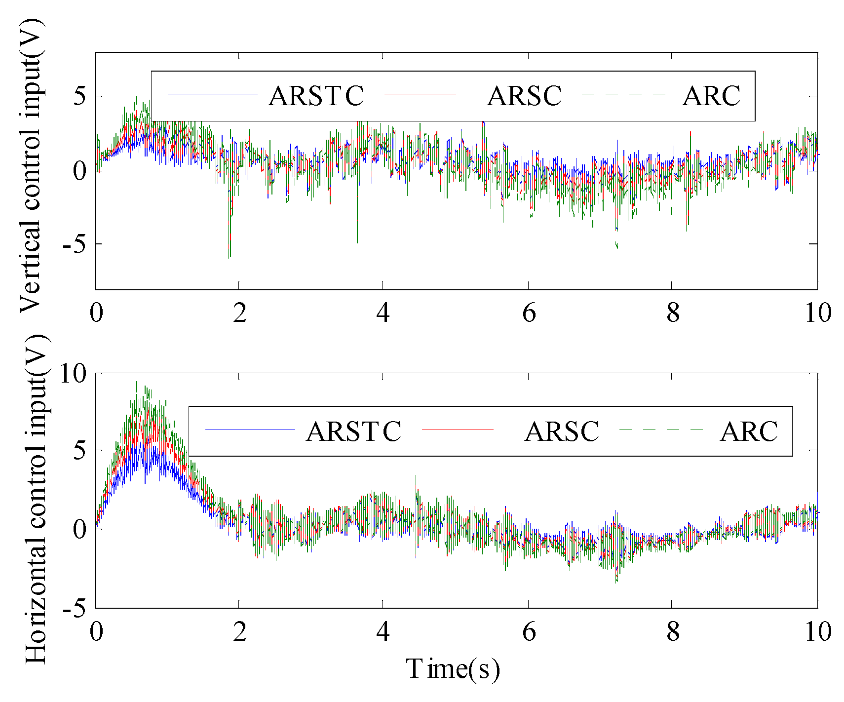
Figure 9, which prove the reliability for parameter adaptive function derived based on the Lyapunov function. The control input processes are presented in
Figure 10, and they are continuously bounded. The results in
Figure 10 show that the high frequency chattering of the control inputs of ARSTC is lower than that of ARSC for both vertical and horizontal subsystems, and the amplitude of the control inputs of ARC is the most drastic. This result shows the advantage of integrated friction compensation and nonlinear robustness of the proposed ARSTC controller, which has the lowest control cost.
4.2. Servo Angle Signal Tracking
We further verify the dynamic tracking performance of the TCEAS. Within the time range of 0 to 3 seconds, the reference motion angle signal of the vertical subsystem is , and the reference motion angle signal of the horizontal subsystem is . When the time is greater than 3 s, the vertical and horizontal subsystems switch to servo motion angle signals, respectively: and . The simulation time is set to 10 s. This design captures both extreme transitions (t = 3 s) and continuous tracking of the two key operational modes for military electromechanical systems. The given expected tracking angle signal can test the dynamic tracking effect and servo stability accuracy of the proposed control strategy.
From
Figure 11 and
Figure 12, it is clear that the ARSTC strategy still ensures the best tracking performance for TCEAS. Even when the angular command of follower tracking is completed under highly maneuverable driving environment, the stabilization accuracy of the vertical subsystem can still reach 0.1450 mrad, and the stabilization accuracy of the horizontal subsystem can reach 0.5482 mrad. The various indicators in
Table 3 and
Table 4 indicate that the control performance of ARSTC is superior to that of the ARSC controller. Furthermore, the control effect of the ARC controller, without considering the nonlinear robust control law, is still the worst. The above results indicate that in this paper, by combining the methods of friction feedforward compensation and parameter adaptation, the influence of friction in TCEAS is reduced.
By comparing
Figure 6,
Figure 7,
Figure 13 and
Figure 14 and
Table 1,
Table 2,
Table 3 and
Table 4, with the change in the tracking command, the stability performance of the TCEAS during sinusoidal servo angle tracking has decreased to a certain extent compared with that during positioning angle signal tracking. This indicates that the servo tracking process has a relatively obvious influence on the stability accuracy of the TCEAS, which reflects the importance of a high-performance stable tracking controller from the side. When tracking sinusoidal angle signals, the control inputs of the TCEAS are shown in
Figure 15, and they are also continuously bounded.
4.3. Discussion of Engineering Insights
The continuously differentiable friction model avoids discontinuity issues common in traditional piecewise models (e.g., Stribeck effect), making it more suitable for real-time control systems where smooth transitions are critical. The continuous differentiability also distinguishes it from the LuGre model, whose simplified discrete implementations may introduce velocity-dependent discontinuities in coupled systems. To specifically verify the effectiveness of friction compensation, ARSC (without friction compensation) is designed as a contrast. The consistent reduction in tracking errors (Me, Ae, Se) of ARSTC compared to ARSC under both positioning and servo tracking conditions (
Table 1,
Table 2,
Table 3 and
Table 4) directly reflects the role of friction compensation in mitigating nonlinear friction effects. Moreover, the smoother control inputs of ARSTC (
Figure 10 and
Figure 15) indicate that friction compensation reduces unnecessary control adjustments caused by friction disturbances, which is crucial for practical engineering applications. These results collectively confirm that friction compensation is not only a theoretical contribution but also brings measurable performance improvements.
The mathematical design of ARSTC—combining adaptive parameter estimation and robust disturbance suppression—directly addresses two conflicting engineering demands. One of these is the adaptive component: In practical applications, electromechanical systems may encounter the problem of gradual parameter drift, such as the coefficient of friction changing with temperature or component aging. The adaptive law enables the controller to “learn” these changes in real time, thus eliminating the need for frequent manual recalibration. The other is the robust component: Sudden disturbances cannot be predicted by adaptive mechanisms alone. Even under Class E road excitation, the nonlinear robust term limits peak positioning angle tracking errors to less than 0.5 mrad, ensuring that the system remains stable during vehicle movement. The bounded control inputs (
Figure 9 and
Figure 14) and stable parameter estimates (
Figure 7 and
Figure 8) confirm that ARSTC is implementable with off-the-shelf hardware.
Figure 8 and
Figure 9 show that parameter estimates stabilize in a bounded range (rather than diverging), which aligns with (31). Although they do not strictly match the true friction parameters, the significant reduction in tracking errors (compared to ARSC) confirms that these estimates are ‘functionally effective’ for friction compensation—a key practical goal for adaptive control in coupled electromechanical systems.
The mathematical framework is generalizable beyond two-axis systems. For example, the state-space formulation (Equation (30)) can be extended to 3+ axis systems (e.g., CNC machine tool spindles) by adding analogous friction and coupling terms, making the design a modular solution for complex actuation challenges.

