Article

A Hybrid Control Approach Integrating Model-Predictive Control and Fractional-Order Admittance Control for Automatic Internal Limiting Membrane Peeling Surgery

1
School of Mechanical Engineering, Xi’an Jiaotong University, No.28, Xianning West Road, Xi’an 710049, China
2
Key Laboratory of Education Ministry for Modern Design and Rotor-Bearing System, Xi’an Jiaotong University, Xianning West Road, Xi’an 710049, China
*
Author to whom correspondence should be addressed.
Actuators 2025, 14(7), 328; https://doi.org/10.3390/act14070328
Submission received: 30 May 2025 / Revised: 26 June 2025 / Accepted: 29 June 2025 / Published: 1 July 2025
(This article belongs to the Special Issue Motion Planning, Trajectory Prediction, and Control for Robotics)

Abstract

As the prevalence of related diseases continues to rise, a corresponding increase in the demand for internal limiting membrane (ILM) peeling surgery has been observed. However, significant challenges are encountered in ILM peeling surgery, including limited force feedback, inadequate depth perception, and surgeon hand tremors. Research on fully autonomous ILM peeling surgical robots has been conducted to address the imbalance between medical resource availability and patient demand while enhancing surgical safety. An automatic control framework for break initiation in ILM peeling is proposed in this study, which integrates model-predictive control with fractional-order admittance control. Additionally, a multi-vision task surgical scene perception method is introduced based on target detection, key point recognition, and sparse binocular matching. A surgical trajectory planning strategy for break initiation in ILM peeling aligned with operative specifications is proposed. Finally, validation experiments for automatic break initiation in ILM peeling were performed using eye phantoms. The results indicated that the positional error of the micro-forceps tip remained within 40 μm. At the same time, the contact force overshoot was limited to under 6%, thereby ensuring both the effectiveness and safety of break initiation during ILM peeling.

1. Introduction

Age-related macular degeneration (AMD) is one of the leading causes of central vision loss in the elderly population. Approximately 196 million people worldwide were affected by AMD in 2020, which is projected to increase to 288 million by 2040 [1]. Diabetic retinopathy (DR), a common complication of diabetes, represents one of the leading causes of blindness among the working-age population worldwide. In 2020, approximately 103 million adults worldwide were affected by DR, and this number is projected to increase to 160 million by 2045 [2]. With the aging population and rising prevalence of chronic diseases, the incidence of these ocular diseases has continued to rise, thereby seriously impacting quality of life and socioeconomic development globally.
Internal limiting membrane (ILM) peeling is a key surgical technique for treating retinal diseases, including macular holes, diabetic macular edema, and high myopic traction maculopathy. It has been demonstrated that ILM peeling can significantly improve the macular hole closure rate (>90%) and postoperative visual recovery by alleviating traction forces at the vitreous–retinal interface [3]. However, traditional surgical procedures require surgeons to possess highly advanced technical skills and extensive experience. Due to the delicate structure of the fundus and limited surgical workspace, even minimal inadvertence during the procedure can result in severe complications, including retinal tears, hemorrhage, or permanent visual impairment [4,5]. Furthermore, precise control of the force applied to the tissue during surgery is challenging, and the absence of a real-time feedback mechanism further increases the risk and complexity of the procedure.
In recent years, extensive research has been conducted to improve the safety and efficacy of microscopic ophthalmic surgeries, including ILM peeling, focusing on the intelligence and automation of micro-ophthalmic surgical robots. Accurate perception of surgical instruments and ocular tissues has become a core challenge for these robots’ trajectory planning and automatic control. Existing perception technologies are classified into optical coherence tomography (OCT)-based and vision-based methods. Zhou et al. [6] employed OCT three-dimensional (3D) point cloud matching with computer-aided design models to achieve six-degree-of-freedom (6-DOF) pose estimation of intraocular needles; however, the instrument model must be prestored and lacks generalizability. El-Haddad et al. [7] integrated binocular vision with active infrared markers in the iOCT system. Although the interactive guidance capability was improved, the multimodal system remained highly complex. This approach is limited by the narrow imaging range and inherent image acquisition delays of OCT, making it challenging to satisfy the real-time dynamic perception requirements during surgery.
Typical vision-based methods are generally classified into three categories as follows: (1) Active light source-assisted methods: Yang et al. [8] reconstructed the retinal surface through structural spot deformation, and Zhou et al. [9,10] utilized spotlight projection to infer instrument pose; however, both methods require modification of the instrument’s integrated light source. (2) Geometric feature analysis methods: Koyama et al. [11] employed the spatial relationship between the instrument tip and its shadow for positioning; however, this approach was sensitive to the light source angle. Ebrahimi et al. [12] optimized needle body positioning through Kalman filtering but could not perceive tissues. (3) Three-dimensional (3D) reconstruction methods: Probst et al. [13] achieved forceps and fundus reconstruction based on the Deep-Matching algorithm; however, failure occurred when the viewing angle varied significantly. Richa et al. [14] detected the proximity between the needle and retina through binocular parallax but could not quantify the spatial pose. The introduction of deep learning technology has enabled new approaches to visual perception. Laina et al. [15] employed a heat map regression network to predict instrument segmentation and two-dimensional pose simultaneously; however, limitations existed in depth estimation. Havlena et al. [16] constructed a retinal model based on preoperative stereo images; however, the reconstruction process was time-consuming and could not be updated intraoperatively. Martinez-Perez et al. [17] achieved retinal 3D reconstruction through vascular tree features but assumed that the eyeball-camera setup remained relatively fixed, thus limiting its clinical applicability.
OCT-based perception technology can provide high-precision tissue information through 3D imaging; however, it is constrained by equipment cost and real-time performance limitations. Uneven micro-surgical instrument surfaces, variable fundus lighting conditions, lack of texture, and suboptimal perception outcomes primarily limit vision-based perception methods. Therefore, the challenge of accurately perceiving surgical forceps pose and ocular tissue in micro-ophthalmic surgical scenarios must be addressed urgently.
For microscopic ophthalmic surgery, the primary types of robots currently employed include auxiliary [18], collaborative [19], remote operation [20,21], partially autonomous [22], and magnetic control types [23]. Due to limitations in surgical scene perception accuracy, trajectory planning and navigation technology development, and surgical safety concerns, the control of ophthalmic surgical robots is primarily focused on robot-assisted ophthalmic surgery. David et al. [24] compared ILM peeling assisted by the Preceyes surgical robot system with manual ILM peeling and found that robot assistance reduced macular retinal hemorrhage and eliminated retinal damage. These findings demonstrate that the application of robotic systems in ophthalmic surgery holds significant potential.
The proportional–integral–derivative (PID) controller is the most commonly employed control method for surgical robots. Uneri et al. [25] used a proportional force controller to adjust the tool tip force of a cooperatively controlled robot. Abedloo et al. [26] implemented a PD controller to achieve robot trajectory control. The standard PID controller serves as the primary controller of IRISS [22] and is utilized to generate commands for the servo motor torque in the IRISS surgical system. The PID controller does not require a model and demonstrates a certain degree of effectiveness in reducing surgical tremor. However, when confronted with internal and external disturbances, the tracking performance and robustness of the PID controller are insufficient and fail to meet the control requirements necessary for fully autonomous ophthalmic surgery.
Force control during contact between surgical instruments and ocular tissues is closely related to surgical safety, and considerable research has been conducted on this topic. Gholami et al. [27] proposed an observer-based adaptive impedance control method, and its effectiveness was demonstrated through simulation studies on the Stereotaxical Micro-telemanipulator for Ocular Surgery robot. Robert A et al. [28,29,30] applied impedance control to impose effective constraints on the movement of Micron handheld robots based solely on virtual visual fixtures; model verification demonstrated a 40–70% reduction in contact force. Wenlei Qin et al. [31,32] proposed a force feedback shared control framework based on a force constraint supervisory controller, significantly reducing the force constraint violation rate.
Model-predictive control (MPC) offers significant advantages in trajectory tracking. Accurate trajectory tracking is a prerequisite for ophthalmic surgical robots to perform surgical actions safely and robustly. Jasmeet et al. [33] proposed a force control method based on MPC to compensate for signal delays affecting surgical robots. The proposed MPC scheme for force control between master and slave stations demonstrates compensation for deterministic delays. Peiyao Zhang et al. [34] developed an autonomous needle navigation strategy for retinal microsurgery based on real-time geometry estimation and chance-constrained MPC, aiming to achieve precise operation, reduce end-to-end surgical time, and improve safety. In addition to its application in ophthalmic surgical robot control, MPC has also been utilized in other robot-assisted surgical procedures [35,36,37].
The development of high-precision, low-risk automated surgical control technology is considered highly significant for improving the safety and robustness of surgical procedures. This advancement helps reduce the incidence of surgical complications and enhances the standardization and reproducibility of procedures, thereby addressing the growing demand for ophthalmic surgery. In recent years, research on intelligent perception and control methods for robot-assisted vitreoretinal surgery has progressed, yet no reports have described fully autonomous navigation or autonomous ILM peeling. A surgical scene perception method based on microscopic binocular vision has been proposed to address challenges posed by the lack of texture in intraocular tissue and surgical instruments. This method combines target detection, keypoint recognition, and binocular sparse matching within a multitask framework to achieve recognition of surgical forceps pose, macula center positioning, and sparse 3D reconstruction of fundus tissue during surgery. The initiation of ILM peeling is considered the most significant challenge due to the absence of natural breaks or flaps in the intact ILM, which forceps can grasp. An automatic surgical trajectory planning method is proposed for initiating ILM breaks during surgery, as per established ILM peeling specifications. To satisfy the demand for high-precision compliant control of the contact force between surgical forceps and the ILM during surgery, an automatic control method combining MPC and fractional-order admittance control (FOAC) is proposed. The method constructs a model-predictive controller for the micro-forceps tip position based on the robot’s kinematic model and employs a fractional-order admittance model to accurately capture the compliance characteristics required during contact between the surgical robot and the ILM.
The main contributions of this paper are summarized as follows:
  • A multivision task surgical scene perception method based on microscopic binocular vision combined with target detection, key point recognition, and sparse 3D reconstruction is proposed.
  • An automatic surgical trajectory planning method for initiating breaks in the ILM during surgery is proposed.
  • An automatic control approach integrating MPC and FOAC is proposed to achieve more precise position and force control.
Section 2 details the control framework, the surgical scene perception method, the surgical trajectory planning method, and the hybrid control approach integrating MPC and FOAC. Section 3 demonstrates the superiority of MPC and FOAC through simulation. Section 4 evaluates the effectiveness and performance advantages of the proposed surgical framework and control method through ILM break initiation experiments. Section 5 summarizes the paper and discusses future research directions.

2. Methods

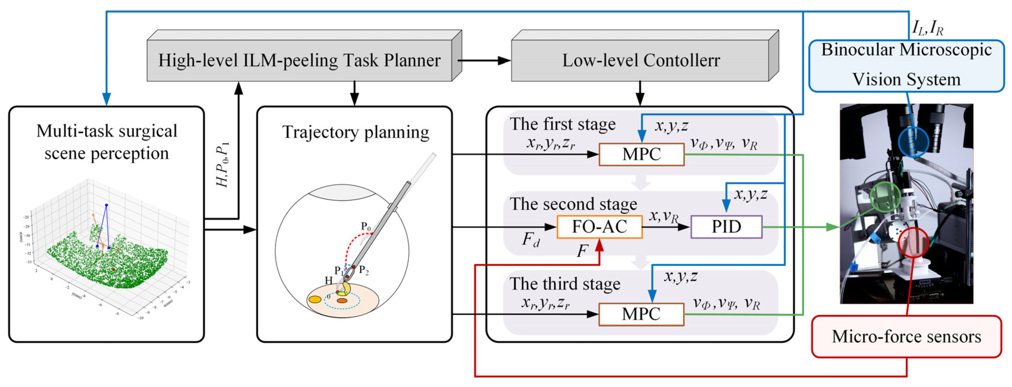
2.1. Control Framework for Automatic Break Initiation in ILM Peeling

The control framework of the automatic ILM peeling method proposed in this study is illustrated in Figure 1. First, left and right images captured by the microscopic binocular vision system are utilized to obtain sparse 3D reconstructions of the ILM, the micro-forceps’ pose, and the macular hole’s center via a multivision task surgical scene perception method. Then, the trajectory of the micro-forceps for operating is planned through the surgical trajectory planning method. Finally, break initiation in ILM peeling surgery is achieved through the proposed hybrid control approach integrating MPC and FOAC, leveraging real-time feedback of micro-forceps pose and contact force. As shown in Figure 1, visual feedback, contact force feedback, and control signals are represented by blue, red, and green arrows, respectively.
The entire surgical process is divided into three stages. In the first stage, the robot can reach the starting point of ILM peeling along a predetermined trajectory based on MPC using only position feedback. In the second stage, micro-forceps contact with the ILM is controlled using the FOAC method, allowing the contact force to smoothly reach a preset threshold, ensuring that the micro-forceps neither cause destructive contact with the fundus nor fail to clamp the internal limiting membrane. In the third stage, the micro-forceps are controlled using MPC to lift the ILM along a predetermined trajectory and to oscillate slightly left and right to initiate a break in the ILM. Finally, the micro-forceps are opened to complete the operation.

2.2. Hybrid MPC–FOAC Control Method

Robotic systems used in vitreoretinal surgery require stringent positional accuracy of the micro-forceps and precise regulation of their contact force with fundus tissue. These requirements are essential to ensure surgical safety. The MPC method explicitly incorporates system constraints into the control optimization process. By accounting for the operational workspace of the micro-forceps and the intraocular constraints present during ILM peeling, MPC confines the robot to a predefined safe operating range. Leveraging its rolling optimization mechanism, MPC can rapidly replan in response to minor intraoperative changes in the ocular environment, ensuring high-precision tracking of the reference trajectory. Compared to conventional admittance control, FOAC more accurately characterizes the system’s dynamic response, delivers smoother instrument–tissue interactions, minimizes contact-force overshoot, and thereby enhances operational safety. Therefore, a hybrid control strategy combining MPC and FOAC was employed for ILM peeling surgery.
This study is based on the Ophthalmic micro-Surgical Robot (OmSR), a 5-DOF robot for posterior segment eye microsurgery [38] previously studied by the team, to investigate the control of autonomous ILM peeling surgery. Since OmSR usually requires high-precision but low-speed operations, factors such as inertia and friction are considered to have a relatively minor impact; therefore, a prediction model within the MPC framework was constructed based on the robot’s kinematic model. According to the robot forward kinematic model [39], the speed of the micro-forceps tip of the OmSR is expressed as follows:
x ˙ = R ˙ cos ( Ψ ) + R sin ( Ψ ) Ψ ˙ y ˙ = R ˙ sin ( Φ ) + R cos ( Φ ) Φ ˙ z ˙ = R ˙ sin ( Ψ ) cos ( Φ ) R cos ( Ψ ) cos ( Φ ) Ψ ˙ + R sin ( Ψ ) sin ( Φ ) Φ ˙
among these, R, Φ, and Ψ represent the joint variables of the OmSR associated with the micro-forceps tip position. The micro-forceps tip position is chosen as the state variable and is defined as follows:
χ = [ x , y , z ] T .
The input is defined as the joint speed of the OmSR and is expressed as follows:
u = [ Φ ˙ , Ψ ˙ , R ˙ ] T .
By combining the forward and inverse kinematics models of the OmSR with Equation (2), the following differential equations governing the state variables are obtained:
χ ˙ = f ( χ , u ) = R ˙ x M v + Ψ ˙ M v 2 x 2 R ˙ y M v + Φ ˙ M v 2 y 2 R ˙ z M v + x Ψ ˙ M v 2 y 2 M v y z Φ ˙ M v M v 2 y 2
among these,
M v = ( x 2 + y 2 + z 2 + ( x 2 + y 2 + z 2 ) 2 4 x 2 y 2 ) / 2 .
Given a reference trajectory for the micro-forceps tip position, each point along the reference trajectory satisfies Equation (4). The nonlinear model represented by Equation (4) at the reference point is linearized using a Taylor expansion, with higher-order terms neglected. The linearized trajectory error model of the forceps tip point is subsequently obtained as follows:
χ ˜ = x ˙ x ˙ r y ˙ y ˙ r z ˙ z ˙ r = f ( χ , u ) χ x x r y y r z z r + f ( χ , u ) u Φ ˙ Φ ˙ r Ψ ˙ Ψ ˙ r R ˙ R ˙ r = a x x r y y r z z r + b Φ ˙ Φ ˙ r Ψ ˙ Ψ ˙ r R ˙ R ˙ r .
By applying forward Euler discretization and linearization to Equation (6), the state equation is obtained as follows:
χ ˜ ( k + 1 ) = ( T a + E ) χ ˜ ( k ) + T b u ˜ ( k ) = a ˜ χ ˜ ( k ) + b ˜ u ˜ ( k )
where T is the sampling time. The output equation is defined as
y ( k ) = c ˜ χ ˜ ( k ) .
Since the output is selected as a state variable, it follows that
c ˜ = E .
To address the steady-state error issue in basic MPC, incremental MPC is employed, and the new state variable at the current time step k is defined as
ξ ( k ) = χ ˜ ( k ) u ˜ ( k 1 ) .
The new state and output equations are given as follows:
ξ ( k + 1 ) = A ξ ( k ) + B Δ u ˜ ( k ) ,
η ( k ) = C ξ ( k ) .
Among these,
A = a ˜ b ˜ 0 m × n I m , B = b ˜ I m , C = I n 0 n × m ,
where n and m denote the dimensions of the state and control vectors, respectively. MPC employs a receding horizon optimization approach to compute the optimal control input at the current time step. The objective function is designed to ensure that the micro-forceps tip tracks the reference trajectory quickly and smoothly; therefore, terms penalizing system state deviation and control input are included. The state Equation (11) and output Equation (12) are derived through multiple steps, upon which the optimization objective function is constructed. Finally, the model predictive control problem is formulated as a standard quadratic programming problem as follows (see Appendix A for detailed derivation):
min Δ U J = 1 2 Δ U T H Δ U + g T Δ U s . t . A I Δ U t U max U t A I Δ U t U min + U t Δ U min Δ U Δ U max
During the ILM peeling procedure, precise control of the contact force between the micro-forceps and the ILM is required. Admittance control is a classical method for achieving contact force control between the robot and its environment, and fractional-order control theory has garnered considerable attention recently for its ability to characterize system dynamics accurately. To ensure smooth contact between the micro-forceps and fundus tissue, this study introduces a fractional-order admittance model based on the traditional admittance model to mitigate contact force overshoot and enhance operational safety. The fractional-order admittance model describing the contact between the micro-forceps and fundus tissue is constructed as follows:
F e F d = M f D α x D α x d + B f D β x D β x d + K f x x d
among these variables, Fd denotes the desired contact force. At the same time, Fe represents the externally applied force, i.e., the actual contact force sensed by the micro-force sensor at the end of the OmSR. Mf, Bf, and Kf are the inertia, damping, and stiffness coefficient matrices, respectively; α and β denote the differential orders corresponding to the expected inertia and damping; D represents the derivative operator; and x and xd represent the actual and desired displacements, respectively. Let Δx = xxd and ef = FeFd; then, Equation (15) can be rewritten as
e f = M f D α Δ x + B f D β Δ x + K f Δ x .
A Laplace transform is further applied to Equation (16) and rewritten in the form of a transfer function, yielding
H ( s ) = Δ X ( s ) E f ( s ) = 1 M f s α + B f s β + K f .
This study adopts the Grünwald–Letnikov definition of fractional calculus and employs the fractional-order operator fitting method using the Oustaloup filter to achieve integer-order approximation and discretization of the fractional-order admittance controller.
When the micro-forceps contact the ILM, the fundus tissue behaves like a spring, and thus the externally applied contact force can be expressed as
F e = K r ( x e x ) .
where Kr denotes the equivalent spring stiffness of the fundus tissue, and xe is the static position of the ILM.

2.3. Surgical Scene Perception Method Based on Multivision Tasks

To achieve automatic control of the OmSR and accomplish the surgical task of peeling the ILM, obtaining key information about the surgical scene through the microscopic binocular vision system is crucial for trajectory planning and navigation of the OmSR. In the surgical scene of ILM peeling, several challenges exist in perceiving the pose of the micro-forceps and the shape of the fundus tissue from visual information. First, the micro-forceps integrated on the end effector of the OmSR are metallic, lack sufficient texture, and easily produce highly reflective areas; second, the fundus tissue also lacks texture; third, the illumination area created by the fiber optic lamp during the operation exhibits uneven brightness.
In the wide-baseline microscopic binocular vision system previously studied by our team, obvious differences were found to exist in the perspectives of the micro-forceps captured in the left and right images. The conventional binocular matching method fails to identify valid matching points between the left and right images. Therefore, considering the inherent geometric structural characteristics of the micro-forceps, a keypoint recognition algorithm has been employed to identify three key points on the micro-forceps, including the two forceps tips and the central point where the forceps shaft meets the tip. Although the shape and size of the fovea of the fundus vary among patients, its texture and color are distinctly different from the surrounding area; therefore, a target detection method is utilized to estimate its position. Regarding the perception of the 3D shape of fundus tissue, due to the unclear texture of blood vessels and other fundus features under the lighting conditions of the operation, accurate dense binocular stereo matching cannot be achieved. Therefore, a sparse binocular matching method is adopted to perform sparse matching of the left and right fundus images.
YOLO11 [39], a state-of-the-art network capable of joint object detection and key-point localization, provides a favorable trade-off between inference speed and accuracy. Given the requirement for real-time visual navigation and feedback, YOLO11 was therefore selected. Accurate perception of fundus geometry relies on robust stereo correspondence; in data-scarce intraocular scenes, network generalization is a critical factor. The GIM [40] framework significantly improves the generalization performance of three leading matching models and is thus adopted for fundus-shape estimation. Based on the above analysis, a multivision task surgical scene perception method was proposed to perform target detection, keypoint recognition, and binocular sparse matching reconstruction utilizing YOLO11 and GIM. This method aims to obtain the 3D coordinates of the macular center, the 3D coordinates of three key points of the micro-forceps, and the sparse point cloud of the ILM. The pose of the micro-forceps is determined from the three identified key points. The pseudocode of the proposed multivision task surgical scene perception algorithm is provided in Algorithm 1.
Algorithm 1 Multivision-task-based Surgical Scene Perception
Input: Left image IL, Right image IR.
Output: Position of macular center Pmc, Position of the micro-forceps Pmf, sparse point cloud of ILM PointCloudILM, Pose of the micro-forceps Posemf.
1:
  (kpmf_L, kpmc_L, kpmf_R, kpmc_R) ← YOLO11_keypoint_detection(IL, IR);
2:
  (bboxmacular_L, bboxmacular_R) ← YOLO11_target_detection(IL, IR);
3:
  matchesILM ← DIM_SparseStereoMatching(IL, IR);
4:
  (MCL, MCR) ← MacularCenter (bboxmacular_L, bboxmacular_R);
5:
  Pmc ← Triangulate(MCL, MCR);
6:
  for i ← 1 to 3 do
7:
         Pmf [i] ← Triangulate(kpmf_L[i], kpmf_R[i]);
8:
  end
9:
  PointCloudILM ← Triangulate(matchesILM);
10:
Posemf ← CalculatePoseFrom3Keypoints(Pmf);
11:
return Pmc, Pmf, PointCloudILM, Posemf;

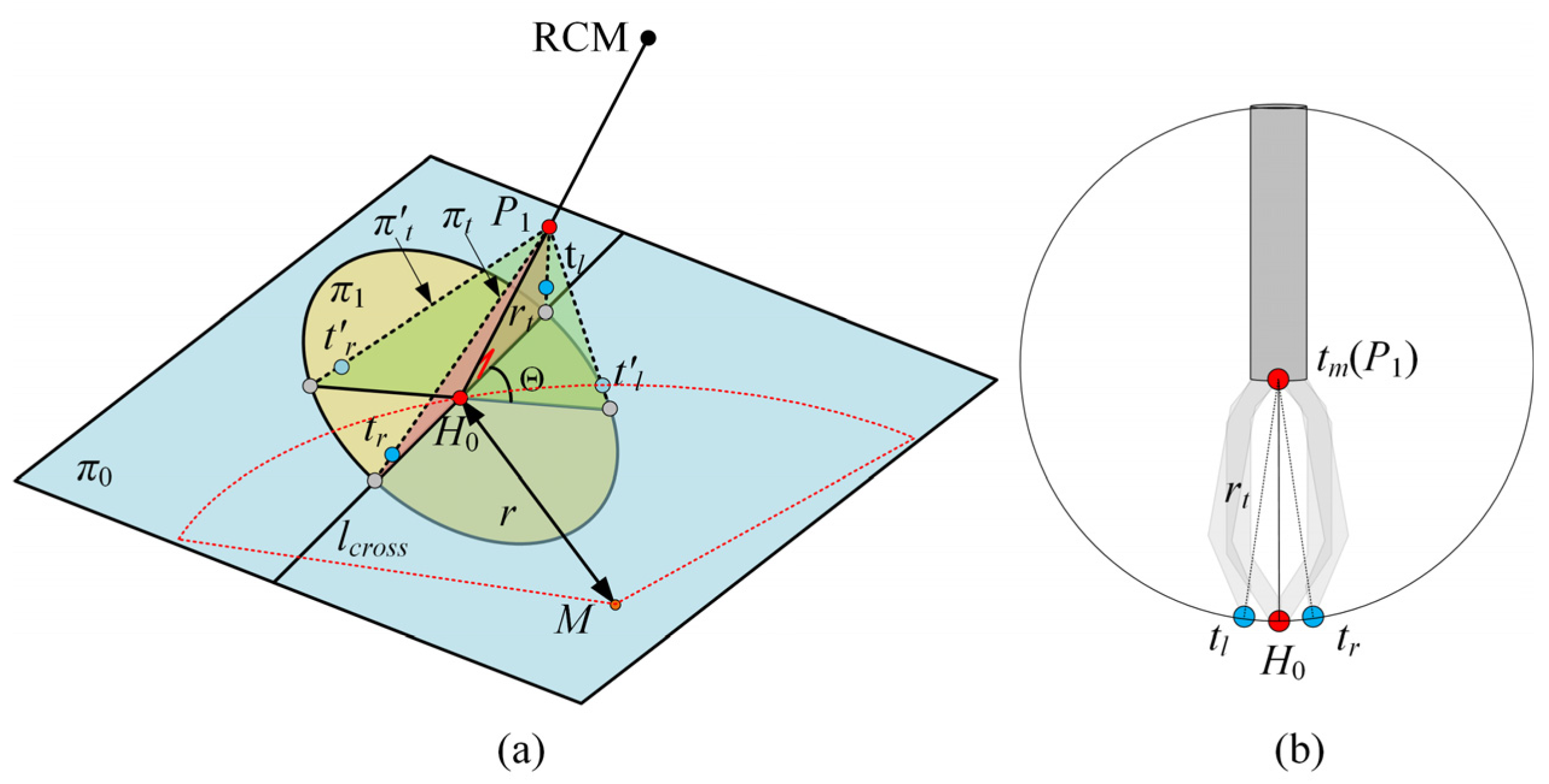
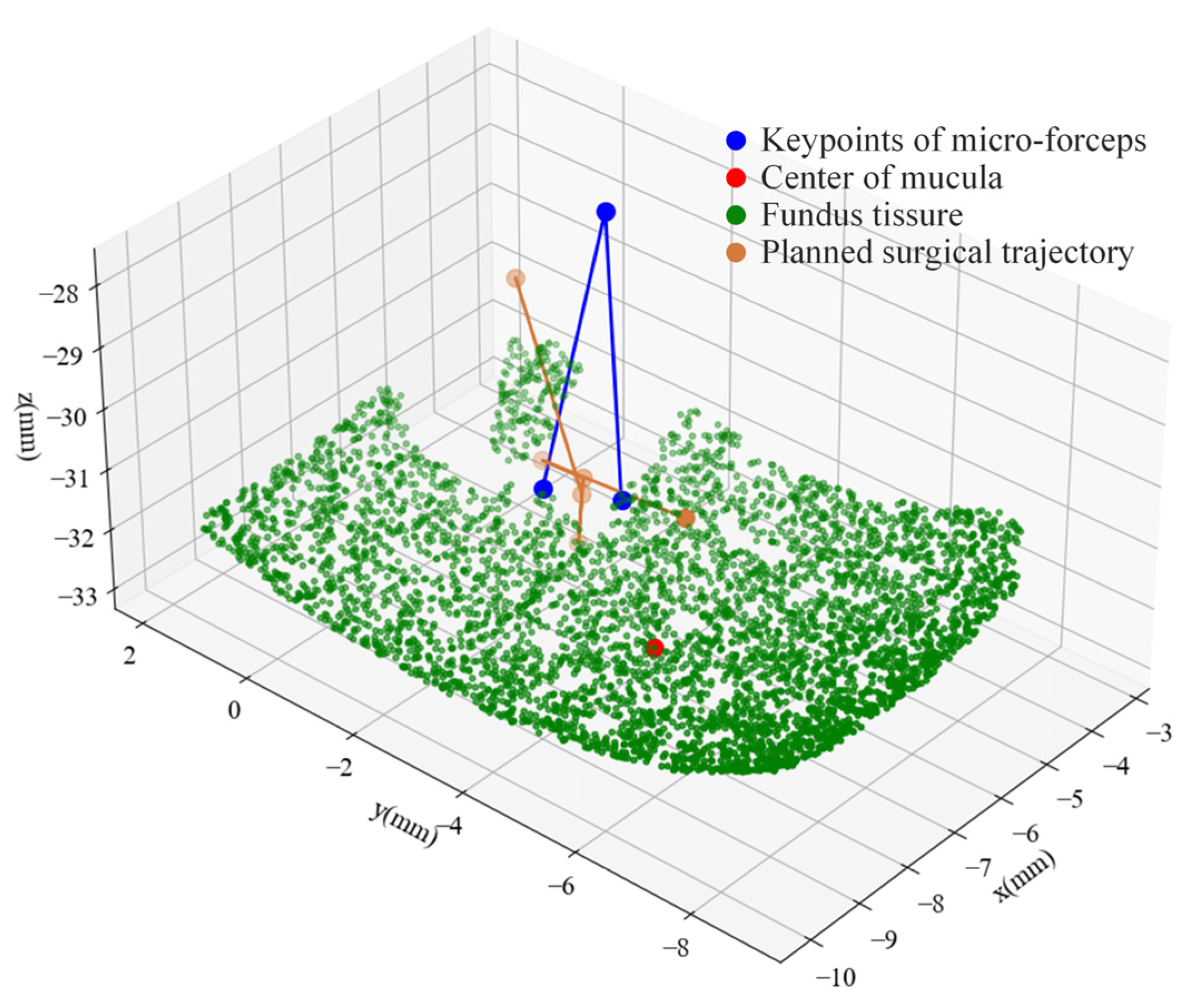
2.4. Automatic Surgical Trajectory Planning Method

The surgical process was divided into three stages based on surgical guidelines for ILM peeling [41], surgical videos [42], and expert advice from ophthalmic surgeons. This study focused on the automatic peeling of the ILM through multimodal integration of vision and tactile feedback. As illustrated in Figure 2, the first stage is defined as the transition of the micro-forceps from position P0 to P1. The axial endpoint of the forceps shaft near the tip defines the position of the micro-forceps. P0 is located at a safe distance from the fundus and within the field of view of the binocular microscope; P1 denotes the initial point for ILM peeling. Upon arrival of the micro-forceps at P1, the second stage is initiated. The OmSR control mode is switched from MPC-based position control to FOAC to enable smooth and safe motion along the R direction, guided by the expected contact force between the micro-forceps and the ILM. Once stable contact between the micro-forceps and the ILM is maintained for a sufficient duration, the position remains fixed, and the micro-forceps transitions from the open state FT(γ0) to the closed state FT(γ1), thereby grasping the ILM. Here, γ0 and γ1 represent the angles between the two jaws in the fully open and fully closed states. The planning of P1 is based on the grasping point H0, the geometric dimensions of the micro-forceps jaws, and the pose of the micro-forceps. The third stage involves moving the micro-forceps from P1 to P2 along the R direction to detach the ILM. To facilitate the break initiation of the ILM, a slight oscillatory motion of the micro-forceps along the Φ direction is required during the transition from P1 to P2, promoting ILM separation from the underlying fundus tissue.
The selection and determination of point P1 during the procedure are described below. As illustrated in Figure 3a, the ILM is peeled around the macular hole center (point M), forming an approximately circular area with a radius of r = 1.5–2 mm. To improve procedural efficiency, the initial clamping point H0 is selected as the point nearest to the Remote Center of Motion (RCM) of the OmSR on the boundary of the circular peeling area. As shown in Figure 3b, when the micro-forceps are engaged, the distance between the center of the forceps shaft endpoint (tm) and the clamping point (H0) is defined as rt. Accordingly, point P1 is selected along the line connecting the RCM and H0, which is located at a distance rt from H0.
The pose of the micro-forceps at point P1 significantly influences the effectiveness of grasping the ILM. An improper pose of the micro-forceps may fail to securely grasp the ILM. Therefore, proper planning of the micro-forceps pose at point P1 is essential. As illustrated in Figure 3a, a sparse point cloud within a 1 mm radius around the clamping point H0 is extracted to fit a local plane, denoted as π0. Plane π1 is defined to pass through H0 and be perpendicular to the line segment connecting P1 and H0. The intersection line of π0 and π1 is denoted as lcross. At point P1, the left and right jaws of the micro-forceps are expected to lie within a plane πt, defined by the intersection line lcross and the segment H0P1, ensuring smooth ILM grasping upon jaw closure. Only the rotational adjustment around the central axis of the micro-forceps is considered. Assuming that upon arrival at P1, the initial plane formed by the micro-forceps tips (tip_L′, tip_R′, P1) is denoted as πt′, the angle Θ between πt′ and the target plane πt represents the required micro-forceps rotation as follows:
Θ = arccos n t n t n t n t .
where nt and nt′ represent the normal vectors of the plane πt (tip_L, tip_R, P1) and the plane πt′ (tip_L′, tip_R′, P1), respectively.
The key to determining the plane πt (tip_L′, tip_R′, P1) lies in estimating the pose of the micro-forceps. Estimating the micro-forceps pose in the θ direction is performed by tracking the coordinates of two points at the micro-forceps’ tips. Based on the structural and kinematic characteristics of the OmSR [39], the relationship between its joint variables (Φ, Ψ) and the pose of the micro-forceps tip can be derived within the robot coordinate system. The transformation matrix between the initial and current poses of the micro-forceps is defined as follows:
tip _ L = R x ( Φ ) R y ( π 2 Ψ ) tip _ L tip _ R = R x ( Φ ) R y ( π 2 Ψ ) tip _ R .
where
tip _ L = 0 0.5 d i , tip _ R = 0 0.5 d i
R x ( Φ ) = 1 0 0 0 cos ( Φ ) sin ( Φ ) 0 sin ( Φ ) cos ( Φ ) , R y ( π 2 Ψ ) = cos ( π 2 Ψ ) 0 sin ( π 2 Ψ ) 0 1 0 sin ( π 2 Ψ ) 0 cos ( π 2 Ψ )

3. Simulation

3.1. Simulation and Analysis of MPC

For position control of the OmSR in this study, an MPC method based on its kinematic model was proposed. A simulation was conducted to evaluate trajectory tracking performance and to compare the proposed method with the classical proportional–integral–derivative (PID) control, sliding mode control (SMC), linear quadratic regulator (LQR), and backstepping control (BC) approach. In the PID, SMC, LQR, and BC, joint variables of the OmSR were directly used as control inputs. In contrast, the MPC method adopted joint velocities as inputs based on the predictive control model derived in Section 2.2. In the simulation, the PID controller employed proportional, integral, and derivative gains of Kp = 2, Ki = 0.1, and Kd = 0.05, respectively. The SMC controller used a switching-gain matrix KSMC = diag(0.2, 0.2, 0.2), a sliding-surface coefficient λSMC = diag(1, 1, 1), and a boundary-layer thickness of ϕSMC = 0.01. For the LQR, the state-weighting matrix was QLQR = diag(105, 105, 105) and the control-weighting matrix was RLQR = diag(100, 100, 100). The backstepping controller adopted a position-error gain matrix of KBC = diag(10, 10, 10). The prediction horizon of MPC was Np = 60, the control horizon was Nc = 10, and the weight coefficients were QMPC = 200 × INp and RMPC = INc. The time sampling interval during the control process was 0.05 s. The simulation study evaluated trajectory-tracking performance for three path types: straight lines, sinusoidal curves, and polylines. For each path type, three independent trajectory samples were generated. Figure 4 illustrates the tracking result for one sinusoidal-curve sample. The MPC controller converged to the reference path more rapidly than the alternative controllers and exhibited the closest overlap with the desired trajectory. Figure 5 presents the mean tracking error achieved by each control method across all sample trajectories. Across the entire trajectory set, the mean errors obtained with PID, SMC, LQR, BC, and MPC were 394.870 µm, 57.307 µm, 51.889 µm, 48.505 µm, and 24.473 µm, respectively. These findings confirm that the MPC based on the OmSR’s forward kinematics model yielded the highest trajectory-tracking accuracy among the methods evaluated.

3.2. Impact of Fractional Order on the Dynamic Characteristics of the Admittance Model

The impact of the fractional order on the dynamic characteristics of the admittance model was investigated through simulation. First, the effect of the expected fractional-differential-order α associated with the inertia coefficient was simulated and analyzed. The value of α varied from 1.5 to 2.1 in increments of 0.1. The expected parameters were set as follows: stiffness coefficient of Kf = 20 N·m−1, inertia coefficient of Mf = 10 kg, damping coefficient of Bf = 2·0.7·√KfMf = 19.7990 N·s·m−1, and a fractional differential order associated with the damping coefficient of β = 1. A step response simulation was performed on the fractional-order admittance model. The results are presented in Figure 6a. A decrease in the expected differential order of the inertia coefficient led to reduced overshoot and a shorter time to reach the steady state, while the steady-state value of the system remained unaffected.
Secondly, the effect of the fractional differential order β associated with the damping coefficient on the dynamic characteristics of the admittance control system was analyzed. The value of β varied from 0.5 to 1.1 in increments of 0.1. The stiffness coefficient of Kf = 20 N· m−1, damping coefficient of Bf = 2·0.7·√KfMf = 19.7990 N·s·m−1, and inertia coefficient of Mf = 10 kg were maintained as previously defined, and the α was set to 2. The results are presented in Figure 6b. An increase in β resulted in slower system response, reduced oscillation, and lower overshoot. Therefore, in subsequent experiments, the influence of α and β on response speed, overshoot, and system stability should be carefully considered during parameter selection.

4. Experimental Validation and Results

4.1. Experimental Setup

This study integrated a previously developed OmSR [38], an end-effector equipped with a micro-forceps incorporating integrated micro-force sensing [42], and a binocular microscopic vision system tailored for fundus surgery, forming a robotic system for ILM peeling. As illustrated in Figure 7, the robot possesses five degrees of freedom: three translational degrees (Φ, Ψ, R) for positioning the tip of the micro-forceps; one rotational degree (Θ) for adjusting the orientation; and one degree (γ) for opening and closing the micro-forceps. The binocular microscopic vision system comprises two microscopes and two industrial cameras. The force sensor, which utilizes fiber Bragg gratings (FBGs) as sensing elements, is demodulated by a central wavelength interrogator, and the feedback force is subsequently calculated by the host computer. During the experiment, the surgical field was illuminated using a fiber-optic light source. For the MPC, the prediction horizon was set to Np = 60 and the control horizon to Nc = 10; the associated weighting matrices were QMPC = 200×INp and RMPC = INc. The control loop was executed with a sampling period of 0.05 s. For FOAC, the control parameters were set as Kf = 600, Bf = 400, Mf = 1, α = 1.5, and β = 0.6.
The break initiation experiment in ILM peeling was conducted using four eye phantoms. Each eye phantom was fabricated from silicone and designed as a hemispherical shell with an inner diameter of 20 mm and an outer diameter of 22 mm. The fundus texture was derived from a real surgical video [43], as illustrated in Figure 8a. This pattern was transferred onto the silicone surface using a water-transfer printing technique. The thickness of the ILM ranged from approximately 0.4 μm at the peripheral macular region to about 1.4 μm near the central macula [44]. A polyethylene film with a thickness of 8 μm was selected to simulate the ILM. Because of its greater toughness and increased thickness compared to biological ILM, the polyethylene film was cut into strips and adhered to the simulated fundus to facilitate the simulation of grasping and peeling by micro-forceps. Additionally, the presence of a thin oil film on the silicone surface eliminated the need for additional adhesive, as the polyethylene film adhered naturally to the fundus of the eye phantom. The finished eye phantoms are shown in Figure 8b.

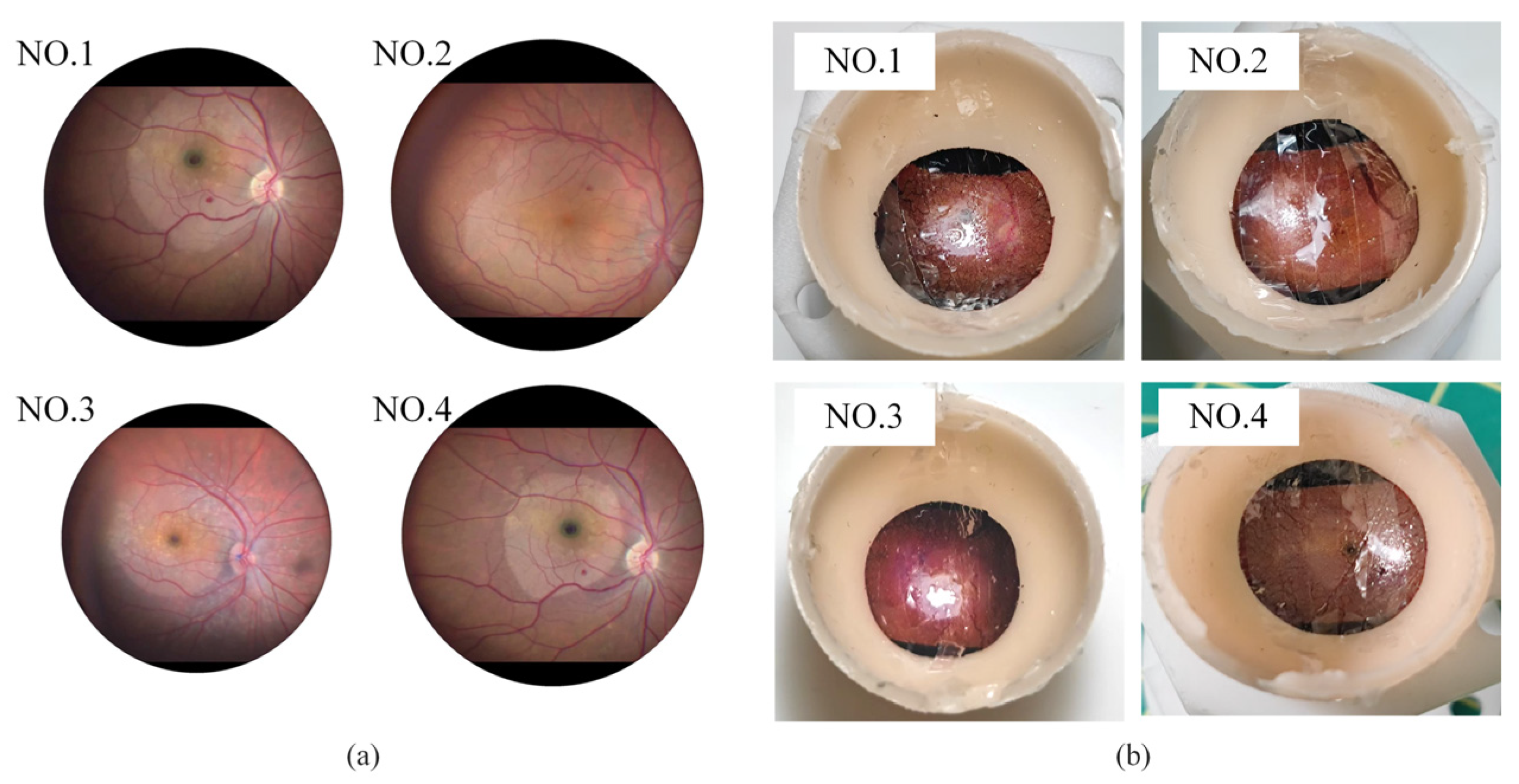
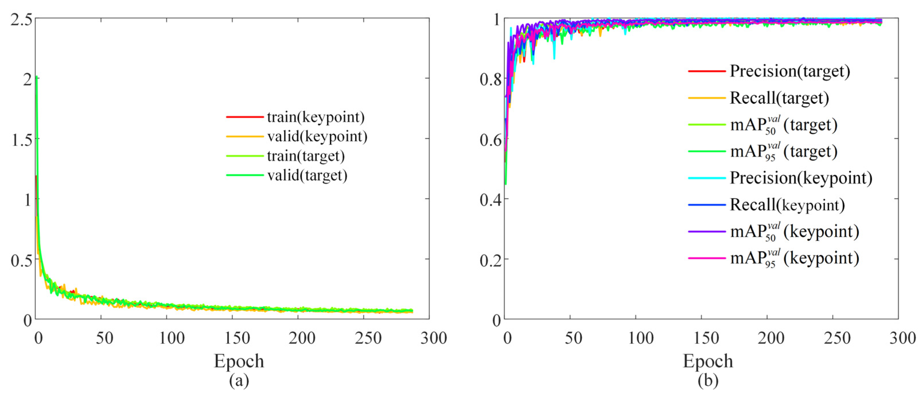
4.2. Surgical Scene Perception Network Training

During the experiment, pretrained target detection and keypoint recognition models based on YOLO11 were required to obtain the real-time coordinates of the micro-forceps key points and the center of the macula. Before the experiment, a total of 1018 images with a resolution of 1920 × 1080 were collected using eye phantoms as the subjects. The sample images are displayed in Figure 9. The collected images were divided into the training set, test set, and validation set at a ratio of 8:1:1. The trained network was based on YOLO11n-pose, and the loss function change curves for both training and validation are presented in Figure 10a. Each loss function converged quickly and continues to decrease throughout the subsequent training process, reaching its minimum value after 287 epochs. As shown in Figure 10b, the recall rates for object detection and keypoint recognition were close to 1 in both the training and validation sets. In the validation set, object detection accuracy was 99.6%, the mAP50 value was 99.5%, and the mAP95 value was 93.8%. The accuracy of keypoint recognition was 99.4%, with the mAP50 at 99.5% and the mAP95 at 97.8%. All metrics reached a relatively high level. The GIM algorithm for sparse binocular matching of the fundus directly utilized the pretrained model GIM-DKM [40].

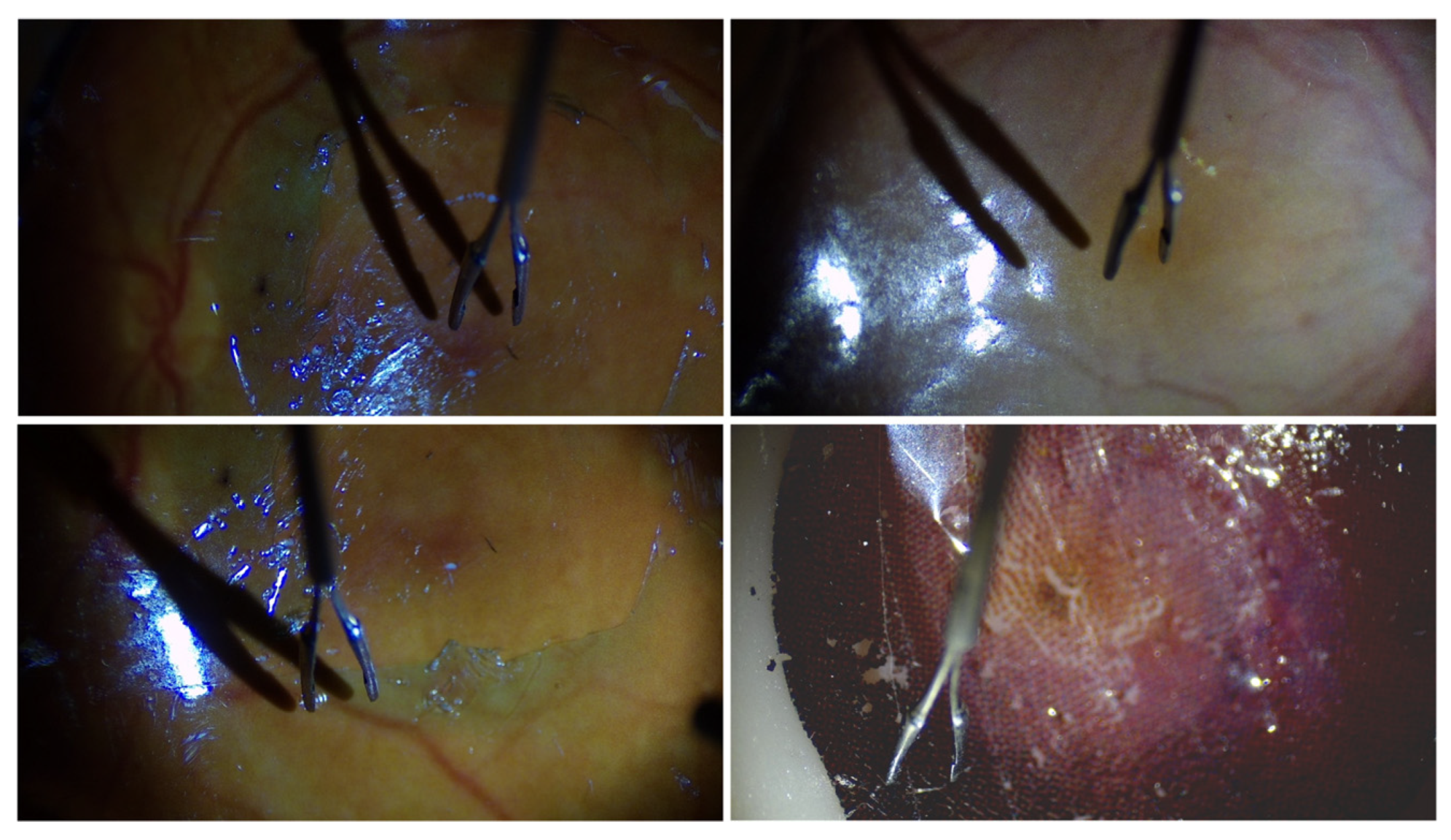
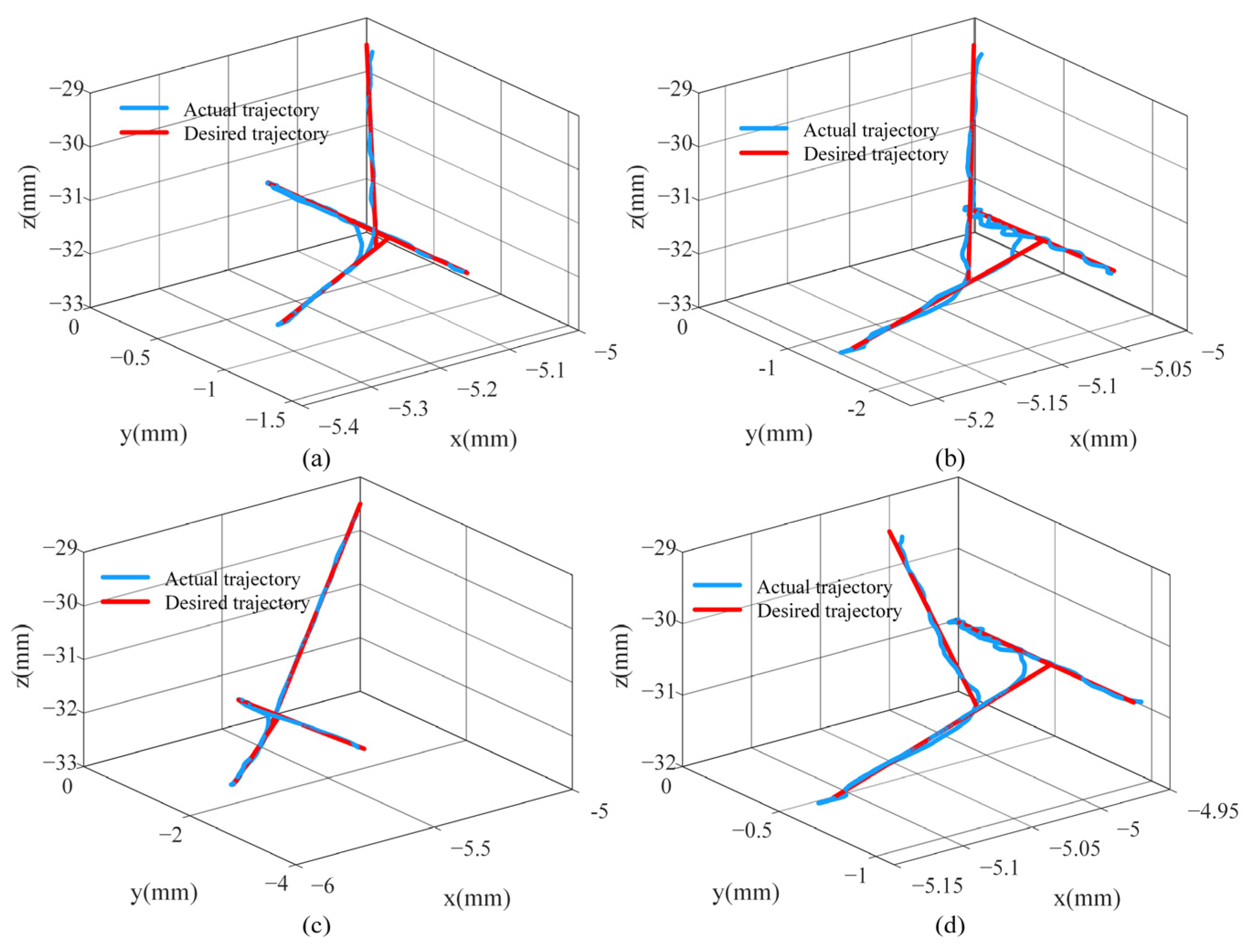
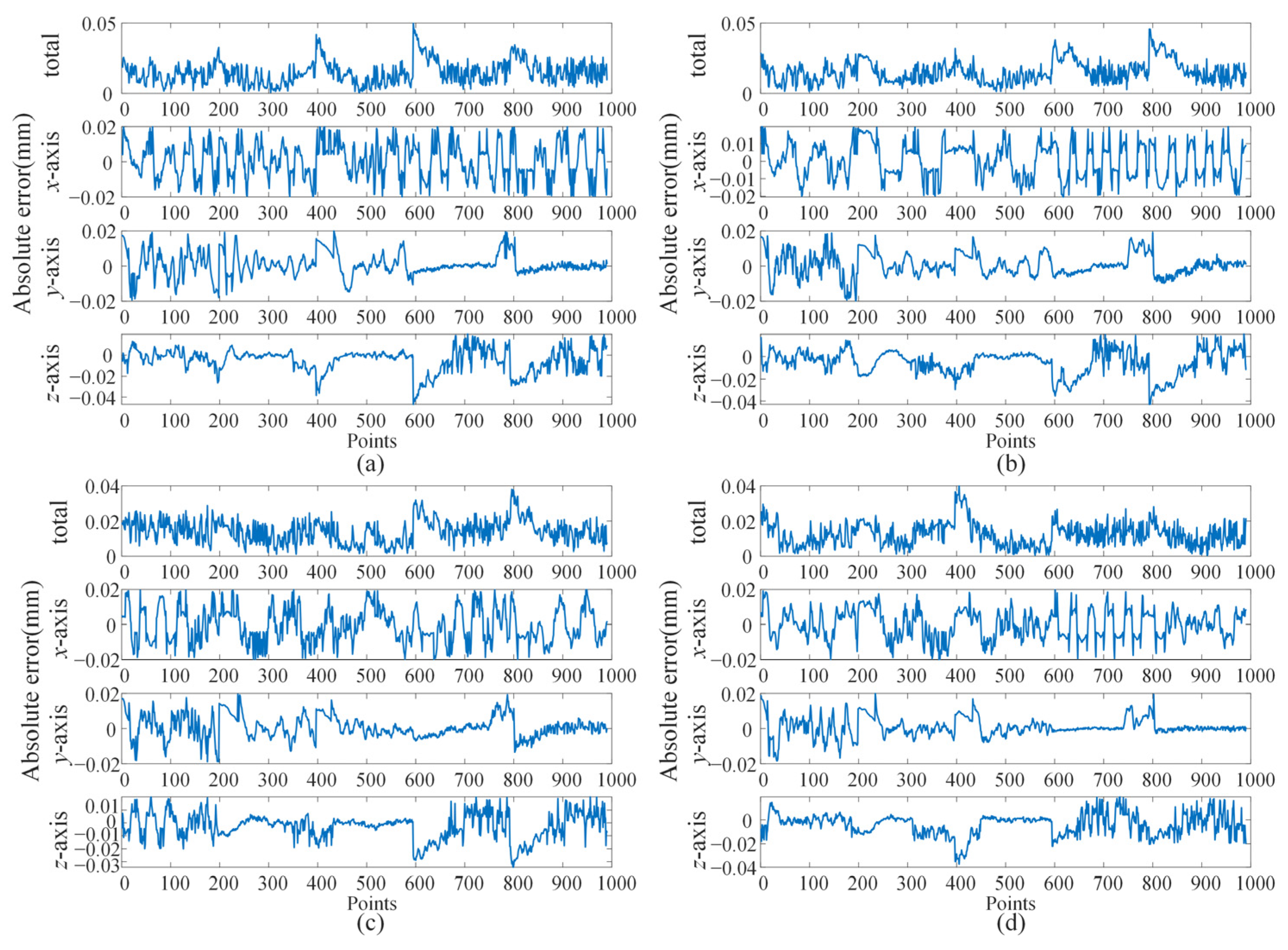
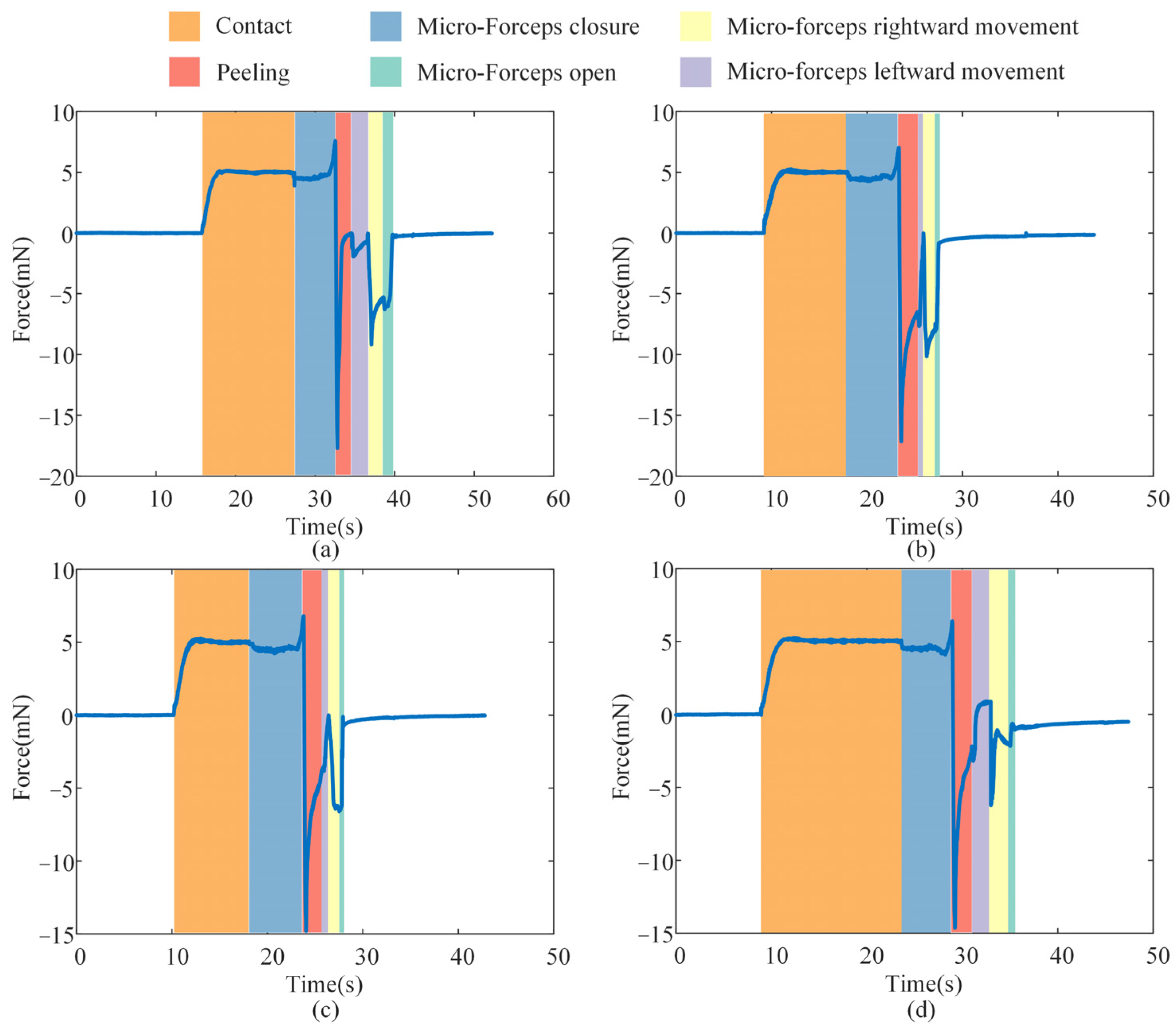
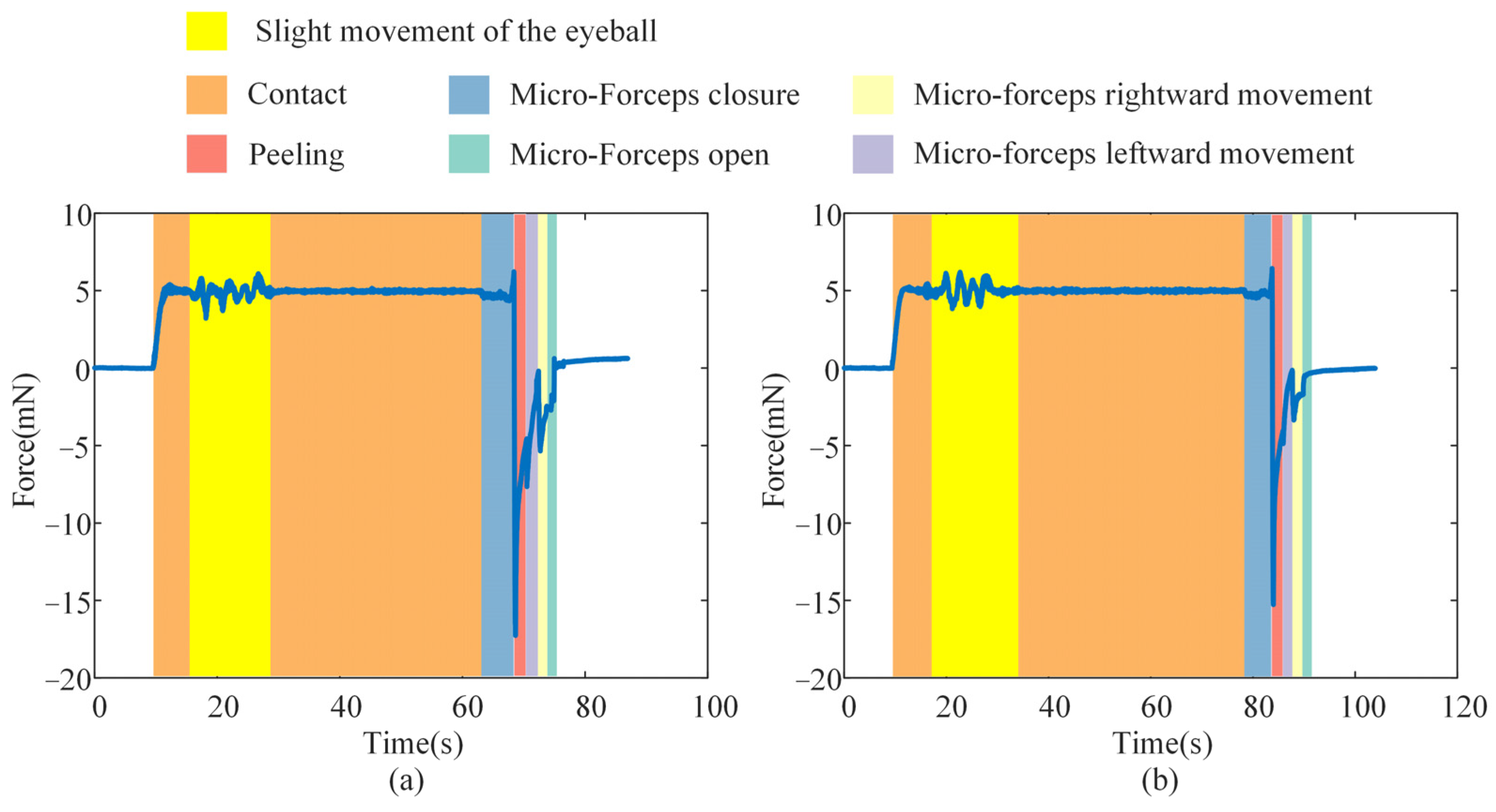
4.3. Break Initiation Experiment in ILM Peeling

The key points obtained by the trained YOLO11 model for the micro-forceps, the macular area, and the results of sparse binocular matching based on GIM are presented in Figure 11. The green points indicate the matched points between the left and right images. The surgical scene perception algorithm proposed above was further employed to reconstruct the surgical scene, including the micro-forceps pose, the macular center, and the fundus tissue. The results are presented in Figure 12. The red dot represents the center of the macular area, the blue dot represents the keypoints of the micro-forceps, and the reference trajectory, obtained according to the proposed ILM peeling surgical trajectory planning method, is shown by the yellow line.
Automatic break initiation experiments in ILM peeling were sequentially performed on four eye phantoms using the trajectory planning and control methods proposed above. As shown in Figure 13, the key surgical stages identified based on the automatic surgical trajectory planning method used during the experiment are presented. Figure 14 compares the planned trajectories with those actually executed in each experiment. Although both sets of curves followed the same overall path, slight mismatches were observed, which are largely attributable to comprehensive positioning errors of the micro-forceps. The micro-forceps pose was obtained via a microscopic binocular vision system, whose accuracy was limited by (i) calibration errors of the vision system, (ii) hand–eye calibration errors between the vision system and the robot, and (iii) keypoint detection errors in the vision algorithm. The trajectory error was more pronounced at the corners because the micro-forceps holding the internal limiting membrane experienced the highest lateral peeling forces in these areas. Owing to its slender structure, the micro-forceps underwent slight deformation under lateral forces, resulting in relatively significant positional errors at the corners. At the corners, the micro-forceps has already been withdrawn from the fundus tissue, mitigating potential safety concerns. Figure 15 depicts the corresponding trajectory tracking errors, and Table 1 summarizes the axial and overall tracking errors for all experiments. The mean absolute tracking errors—35.115 µm, 37.588 µm, 32.962 µm, and 33.762 µm—are each below the 40 µm accuracy threshold recommended for micro-forceps manipulation in vitreoretinal surgery [45]. Consequently, the proposed position control method satisfies the precision requirements for break initiation experiments in ILM peeling.
In clinical procedures, a lack of contact force feedback may cause the micro-forceps to pierce the fundus and result in accidental tissue damage inadvertently. Therefore, the analysis focused on the stage from the initial contact between the micro-forceps and the ILM to the point where the contact force reaches the predefined threshold. Figure 16 presents the contact force detected by the micro-force sensors during the ILM peeling process. Under the FOAC method applied in the second surgical stage, the contact force smoothly reached the preset threshold of 5 mN. The overshoot percentages of the contact force during the contact phase in the four experiments on eye phantom 1, 2, 3, and 4 were 2.72%, 5.24%, 5.13%, and 4.99%, respectively—which can all be considered low. Therefore, the proposed FOAC method can meet the precise contact force control requirements during ILM peeling. During the micro-forceps closure phase, a slight increase in contact force was observed as the micro-forceps moved closer to the ILM. In the four experiments on eye phantom 1, 2, 3, and 4, the increase in contact force values caused by micro-forceps closure were measured as 2.562 mN, 1.997 mN, 1.808 mN, and 1.389 mN, respectively. Therefore, this factor should be considered when setting the contact force threshold. During the ILM peeling phase, the direction of the peeling force was opposite to that of the contact force. The maximum absolute peeling forces observed in the four experiments on eye phantom 1, 2, 3, and 4 were 17.694 mN, 17.158 mN, 14.787 mN, and 14.628 mN, respectively.
To assess the stability of the proposed FOAC method in the presence of slight eyeball motion, we manually perturbed an eye phantom under the same conditions as the ILM-peeling experiment, thereby emulating inadvertent patient movement during surgery. This experiment was conducted twice, and the corresponding contact forces are presented in Figure 17. Slight movement of the eye phantom induced transient fluctuations in the contact force; however, the peak deviations in both trials remained within the safe range—2.870 mN and 2.358 mN, respectively. The contact force promptly returned to its predefined value once the motion ceased. Because involuntary patient movement during actual surgery is typically smaller than the hand-induced perturbations applied here, the resulting force variations in clinical practice are expected to be even lower. These findings indicate that the proposed contact-force control method can ensure safe interaction between the micro-forceps and the ILM.

5. Conclusions

This study addresses three key challenges in automatic ILM peeling using OmSR: inefficient and inaccurate perception of the surgical scene, lack of standardized quantitative trajectories, and imprecise control of the contact force between the micro-forceps and ILM. A multivision task surgical scene perception method was developed, incorporating target detection, keypoint recognition, and sparse binocular matching. A surgical trajectory planning method for break initiation in ILM peeling was formulated based on expert surgical advice and analysis of real ILM peeling videos. A hybrid control approach combining MPC and FOAC was proposed for break initiation in ILM peeling. Experiments verified that during break initiation in ILM peeling by the proposed automatic control framework, the trajectory control error of the surgical forceps remained below 40 μm, and the contact force overshoot was less than 6%, meeting the accuracy and safety requirements of autonomous robotic surgery.
Although silicone-based eye phantoms were employed to model ILM peeling surgery in this study, the fundus textures were reconstructed directly from clinical surgical videos, allowing the intra-operative vision system to perceive illumination, color, and texture distributions that closely resemble those of a real eye. This realistic, yet risk-free environment enabled a rigorous validation of the proposed perception and control methods, thereby providing a solid basis for subsequent experiments on ex vivo animal eyes.

Author Contributions

Conceptualization, X.Z. and H.L.; methodology, H.L.; software, H.L. and Y.W.; validation, H.L., Z.Z., and N.W.; writing—original draft preparation, H.L. and N.W.; writing—review and editing, H.L. and N.W. All authors have read and agreed to the published version of the manuscript.

Funding

This research was funded by the Key Research and Development Projects of Shaanxi Province, grant number 2024GX-ZDCYL-02-16, and the Science and Technology Project of Xi’an, Shaanxi Province, China, grant number 21RGZN0007.

Data Availability Statement

The data in this study are available from the corresponding author upon request. The data are not publicly available due to the existence of a laboratory confidentiality agreement with the collaborators on the project.

Conflicts of Interest

The authors declare no conflicts of interest.

Abbreviations

The following abbreviations are used in this manuscript:
AMDAge-related macular degeneration
DRDiabetic retinopathy
ILMInternal limiting membrane
3DThree-dimensional
OCTOptical coherence tomography
PIDProportional–integral–derivative
MPCModel=predictive control
FOACFractional-order admittance control

Appendix A

A detailed derivation of model predictive control reformulated as a quadratic optimization problem is presented below. Let the prediction horizon be Np and the control horizon Nc, where Np ≥ Nc. The corresponding state-space equation is given as follows:
ξ ( k + 1 ) = A ξ ( k ) + B Δ u ˜ ( k ) .
A multi-step derivation of Equation (A1) yields:
  ξ ( k + 1 ) = A ξ ( k ) + B Δ u ˜ ( k ) ξ ( k + 1 ) = A ξ ( k ) + B Δ u ˜ ( k ) ξ ( k + 2 ) = A ξ ( k + 1 ) + B Δ u ˜ ( k + 1 ) = A 2 ξ ( k ) + A B Δ u ˜ ( k ) + B Δ u ˜ ( k + 1 ) ξ ( k + 3 ) = A ξ ( k + 2 ) + B Δ u ˜ ( k + 2 ) = A 3 ξ ( k ) + A 2 B Δ u ˜ ( k ) + A B Δ u ˜ ( k + 1 ) + B Δ u ˜ ( k + 2 ) ξ ( k + N c ) = A N c ξ ( k ) + A N c 1 B Δ u ˜ ( k ) + A N c 2 B Δ u ˜ ( k + 1 ) + + A 0 B Δ u ˜ ( k + N c 1 ) ξ ( k + N p ) = A N p ξ ( k ) + A N p 1 B Δ u ˜ ( k ) + A N p 2 B Δ u ˜ ( k + 1 ) + + A 0 B Δ u ˜ ( k + N p 1 ) .
The new output equation is:
η ( k ) = C ξ ( k ) .
A multi-step derivation of Equation (A3) yields:
η ( k + 1 ) = C ξ ( k + 1 ) = C A ξ ( k ) + C B Δ u ˜ ( k ) η ( k + 2 ) = C A 2 ξ ( k ) + C A B Δ u ˜ ( k ) + C B Δ u ˜ ( k + 1 ) η ( k + 3 ) = C A 3 ξ ( k ) + C A 2 B Δ u ˜ ( k ) + C A B Δ u ˜ ( k + 1 ) + C B Δ u ˜ ( k + 2 ) η ( k + N c ) = C A N c ξ ( k ) + C A N c 1 B Δ u ˜ ( k ) + C A N c 2 B Δ u ˜ ( k + 1 ) + + C A 0 B Δ u ˜ ( k + N C 1 ) η ( k + N p ) = C A N p ξ ( k ) + C A N p 1 B Δ u ˜ ( k ) + C A N p 2 B Δ u ˜ ( k + 1 ) + + C A 0 B Δ u ˜ ( k + N p 1 ) .
Rewrite the output Equation (A4) into the following form:
Y = X ξ ( k ) + Θ Δ U ,
where,
Y = η ( k + 1 ) η ( k + 2 ) η ( k + N c ) η ( k + N p ) , X = C A C A 2 C A N c C A N p , Δ U = Δ u ˜ ( k ) Δ u ˜ ( k + 1 ) Δ u ˜ ( k + 2 ) Δ u ˜ ( k + N c 1 ) , Θ = C B 0 0 0 C A B C B 0 0 C A N c 1 B C A N c 2 B B C A N p 1 B C A N p 2 B C A N p N c B .
Define the reference output of the system as:
Y r = η r ( k + 1 ) η r ( k + 2 ) η r ( k + N c ) η r ( k + N p ) T = 0 0 0 0 T .
The optimization objective function is defined as:
J = Y ˜ T Q Q Y ˜ + Δ U T R R Δ U = ( Y Y r ) T Q Q ( Y Y r ) + Δ U T R R Δ U = ( X ξ ( k ) + Θ Δ U ) Y r T Q Q ( X ξ ( k ) + Θ Δ U ) Y r + Δ U T R R Δ U = Δ U T Θ T Q Q Θ + R R Δ U + 2 E T Q Q Θ Δ U + E T Q Q E Y r T Q Q Θ Δ U + Y r T Q Q Y 2 Y r T Q Q E ,
where,
E = X ξ ( k ) , Q Q = I N p Q , R R = I N p R .
where QQ is a positive semi-definite state weighting matrix, and RR is a positive definite control weighting matrix. Both matrices are typically assumed to be diagonal. Make the following substitution in Equation (A8):
H = Θ T Q Q Θ + R R , g = E T Q Q Θ .
Then Equation (A8) can be rewritten as:
min Δ U J = 2 1 2 Δ U T H Δ U + g T Δ U min Δ U J = 1 2 Δ U T H Δ U + g T Δ U .
The following recursive equation is employed to determine the control input during the actual operation of the surgical robot:
u ( k ) = u ( k 1 ) + Δ u ( k ) u ( k + 1 ) = u ( k ) + Δ u ( k + 1 ) = u ( k 1 ) + Δ u ( k ) + Δ u ( k + 1 ) u ( k + N c 1 ) = u ( k + N c 2 ) + Δ u ( k + N c 1 ) = u ( k 1 ) + Δ u ( k ) + Δ u ( k + 1 ) + + Δ u ( k + N c 1 ) .
Rewrite Equation (A12) as follows:
U = u ( k ) u ( k + 1 ) u ( k + 2 ) u ( k + N c 1 ) = u ( k 1 ) u ( k 1 ) u ( k 1 ) u ( k 1 ) + I 2 0 0 0 I 2 I 2 0 0 I 2 I 2 I 2 0 0 I 2 I 2 I 2 I 2 Δ u ( k ) Δ u ( k + 1 ) Δ u ( k + 2 ) Δ u ( k + N c 1 ) = U t + A I Δ U t .
Based on the upper and lower bounds of the control input, the following constraint is derived:
U min = u min u min u min u min u ( k ) u ( k + 1 ) u ( k + 2 ) u ( k + N c 1 ) u max u max u max u max = U max
By combining Equations (A13) and (A14), the following result is obtained:
U min U t + A I Δ U t U max A I Δ U t U max U t A I Δ U t U min + U t .
Based on the above derivation, the MPC is reformulated as a standard quadratic programming problem:
min Δ U J = 1 2 Δ U T H Δ U + g T Δ U s . t . A I Δ U t U max U t A I Δ U t U min + U t Δ U min Δ U Δ U max

References

  1. Zhou, Y.; Jia, W.; Song, J.; Li, M.; Dai, W.; Zou, J.; Zhou, J.; Chen, X.; Li, X. Burdens and trends of age-related macular degeneration at global, regional, and national levels, 1990–2021: Findings from the 2021 global burden of disease study. Eye 2025, 39, 1517–1525. [Google Scholar] [CrossRef]
  2. Teo, Z.L.; Tham, Y.; Yu, M.; Chee, M.L.; Rim, T.H.; Cheung, N.; Bikbov, M.M.; Wang, Y.X.; Tang, Y.; Lu, Y. Global prevalence of diabetic retinopathy and projection of burden through 2045: Systematic review and meta-analysis. Ophthalmology 2021, 128, 1580–1591. [Google Scholar] [CrossRef]
  3. Akhtar, S.M.M.; Saleem, S.Z.; Rizvi, S.A.A.; Fareed, A.; Mumtaz, M.; Saleem, S.; Bai, A.; Shaik, A.A.; Kirchoff, R.; Asghar, M.S. Critical analysis of macular hole repair techniques: A comprehensive systematic review and meta-analysis comparing internal limiting membrane flap and internal limiting membrane peeling for any size of macular hole. BMC Ophthalmol. 2025, 25, 174. [Google Scholar] [CrossRef] [PubMed]
  4. Michalewska, Z.; Bednarski, M.; Michalewski, J.; Jerzy, N. The role of ILM peeling in vitreous surgery for proliferative diabetic retinopathy complications. Ophthalmic Surg. Lasers Imaging Retin. 2013, 44, 238–242. [Google Scholar] [CrossRef] [PubMed]
  5. Asencio-Duran, M.; Manzano-Muñoz, B.; Vallejo-García, J.L.; García-Martínez, J. Complications of macular peeling. J. Ophthalmol. 2015, 2015, 467814. [Google Scholar] [CrossRef]
  6. Zhou, M.; Hao, X.; Eslami, A.; Huang, K.; Cai, C.; Lohmann, C.P.; Navab, N.; Knoll, A.; Nasseri, M.A. 6DOF needle pose estimation for robot-assisted vitreoretinal surgery. IEEE Access 2019, 7, 63113–63122. [Google Scholar] [CrossRef]
  7. El-Haddad, M.T.; Tao, Y.K. Automated stereo vision instrument tracking for intraoperative OCT guided anterior segment ophthalmic surgical maneuvers. Biomed. Opt. Express 2015, 6, 3014–3031. [Google Scholar] [CrossRef]
  8. Yang, S.; Martel, J.N.; Lobes Jr, L.A.; Riviere, C.N. Techniques for robot-aided intraocular surgery using monocular vision. Int. J. Robot. Res. 2018, 37, 931–952. [Google Scholar] [CrossRef] [PubMed]
  9. Zhou, M.; Hennerkes, F.; Liu, J.; Jiang, Z.; Wendler, T.; Nasseri, M.A.; Iordachita, I.; Navab, N. Theoretical error analysis of spotlight-based instrument localization for retinal surgery. Robotica 2023, 41, 1536–1549. [Google Scholar] [CrossRef]
  10. Zhou, M.; Wu, J.; Ebrahimi, A.; Patel, N.; He, C.; Gehlbach, P.; Taylor, R.H.; Knoll, A.; Nasseri, M.A.; Iordachita, I. Spotlight-based 3D instrument guidance for retinal surgery. In Proceedings of the 2020 International Symposium on Medical Robotics (ISMR), Atlanta, GA, USA, 18–20 November 2020; pp. 69–75. [Google Scholar]
  11. Koyama, Y.; Marinho, M.M.; Mitsuishi, M.; Harada, K. Autonomous coordinated control of the light guide for positioning in vitreoretinal surgery. IEEE Trans. Med. Robot. Bionics 2022, 4, 156–171. [Google Scholar] [CrossRef]
  12. Ebrahimi, A.; Alambeigi, F.; Sefati, S.; Patel, N.; He, C.; Gehlbach, P.; Iordachita, I. Stochastic force-based insertion depth and tip position estimations of flexible FBG-equipped instruments in robotic retinal surgery. IEEE/ASME Trans. Mechatron. 2020, 26, 1512–1523. [Google Scholar] [CrossRef] [PubMed]
  13. Probst, T.; Maninis, K.; Chhatkuli, A.; Ourak, M.; Vander Poorten, E.; Van Gool, L. Automatic tool landmark detection for stereo vision in robot-assisted retinal surgery. IEEE Robot. Autom. Let. 2017, 3, 612–619. [Google Scholar] [CrossRef]
  14. Richa, R.; Balicki, M.; Sznitman, R.; Meisner, E.; Taylor, R.; Hager, G. Vision-based proximity detection in retinal surgery. IEEE Trans. Bio-Med. Eng. 2012, 59, 2291–2301. [Google Scholar] [CrossRef]
  15. Laina, I.; Rieke, N.; Rupprecht, C.; Vizcaíno, J.P.; Eslami, A.; Tombari, F.; Navab, N. Concurrent segmentation and localization for tracking of surgical instruments. In Medical Image Computing and Computer-Assisted Intervention–MICCAI 2017, Proceedings of the 20th International Conference, Quebec City, QC, Canada, 11–13 September 2017; Proceedings, Part II 20, 2017; Springer: Berlin/Heidelberg, Germany, 2017; pp. 664–672. [Google Scholar]
  16. Havlena, M.; Maninis, K.; Bouget, D.; Vander Poorten, E.; Van Gool, L. 3D reconstruction of the retinal surface for robot-assisted eye surgery. In Proceedings of the Computer Assisted Radiology and Surgery, Heidelberg, Germany, 21–25 June 2016; pp. 112–113. [Google Scholar]
  17. Martinez-Perez, M.E.; Espinosa-Romero, A. Three-dimensional reconstruction of blood vessels extracted from retinal fundus images. Opt. Express 2012, 20, 11451–11465. [Google Scholar] [CrossRef]
  18. MacLachlan, R.A.; Becker, B.C.; Tabares, J.C.; Podnar, G.W.; Lobes, L.A.; Riviere, C.N. Micron: An actively stabilized handheld tool for microsurgery. IEEE Trans. Robot. 2011, 28, 195–212. [Google Scholar] [CrossRef] [PubMed]
  19. He, X.; Roppenecker, D.; Gierlach, D.; Balicki, M.; Olds, K.; Gehlbach, P.; Handa, J.; Taylor, R.; Iordachita, I. Toward clinically applicable steady-hand eye robot for vitreoretinal surgery. In Proceedings of the ASME International Mechanical Engineering Congress and Exposition, Houston, TX, USA, 9–15 November 2012; pp. 145–153. [Google Scholar]
  20. Edwards, T.L.; Xue, K.; Meenink, H.; Beelen, M.J.; Naus, G.; Simunovic, M.P.; Latasiewicz, M.; Farmery, A.D.; De Smet, M.D.; MacLaren, R.E. First-in-human study of the safety and viability of intraocular robotic surgery. Nat. Biomed. Eng. 2018, 2, 649–656. [Google Scholar] [CrossRef] [PubMed]
  21. Nasseri, M.A.; Eder, M.; Nair, S.; Dean, E.C.; Maier, M.; Zapp, D.; Lohmann, C.P.; Knoll, A. The introduction of a new robot for assistance in ophthalmic surgery. In Proceedings of the 2013 35th Annual International Conference of the IEEE Engineering in Medicine and Biology Society (EMBC), Osaka, Japan, 3–7 July 2013; pp. 5682–5685. [Google Scholar]
  22. Kummer, M.P.; Abbott, J.J.; Kratochvil, B.E.; Borer, R.; Sengul, A.; Nelson, B.J. OctoMag: An electromagnetic system for 5-DOF wireless micromanipulation. IEEE Trans. Robot. 2010, 26, 1006–1017. [Google Scholar] [CrossRef]
  23. Maberley, D.A.; Beelen, M.; Smit, J.; Meenink, T.; Naus, G.; Wagner, C.; de Smet, M.D. A comparison of robotic and manual surgery for internal limiting membrane peeling. Graefe’s Arch. Clin. Exp. Ophthalmol. 2020, 258, 773–778. [Google Scholar] [CrossRef]
  24. Üneri, A.; Balicki, M.A.; Handa, J.; Gehlbach, P.; Taylor, R.H.; Iordachita, I. New steady-hand eye robot with micro-force sensing for vitreoretinal surgery. In Proceedings of the 2010 3rd IEEE RAS & EMBS International Conference on Biomedical Robotics and Biomechatronics, Tokyo, Japan, 26–29 September 2010; pp. 814–819. [Google Scholar]
  25. Abedloo, E.; Gholami, S.; Taghirad, H.D. Eye-rhas manipulator: From kinematics to trajectory control. In Proceedings of the 2015 3rd RSI International Conference on Robotics and Mechatronics (ICROM), Tehran, Iran, 7–9 October 2015; pp. 61–66. [Google Scholar]
  26. Wilson, J.T.; Gerber, M.J.; Prince, S.W.; Chen, C.W.; Schwartz, S.D.; Hubschman, J.P.; Tsao, T.C. Intraocular robotic interventional surgical system (iriss): Mechanical design, evaluation, and master–slave manipulation. Int. J. Med. Robot. Comput. Assist. Surg. 2018, 14, e1842. [Google Scholar] [CrossRef]
  27. Gholami, S.; Arjmandi, A.; Taghirad, H.D. An observer-based adaptive impedance-control for robotic arms: Case study in smos robot. In Proceedings of the 2016 4th International Conference on Robotics and Mechatronics (ICROM), Tehran, Iran, 26–28 October 2016; pp. 49–54. [Google Scholar]
  28. Becker, B.C.; MacLachlan, R.A.; Lobes, L.A.; Riviere, C.N. Vision-based retinal membrane peeling with a handheld robot. In Proceedings of the 2012 IEEE International Conference on Robotics and Automation, St. Paul, MN, USA, 14–18 May 2012; pp. 1075–1080. [Google Scholar]
  29. Han, Y.; Routray, A.; Adeghate, J.O.; MacLachlan, R.A.; Martel, J.N.; Riviere, C.N. Monocular vision-based retinal membrane peeling with a handheld robot. J. Med. Devices 2021, 15, 031014. [Google Scholar] [CrossRef] [PubMed]
  30. Wells, T.S.; Yang, S.; MacLachlan, R.A.; Lobes Jr, L.A.; Martel, J.N.; Riviere, C.N. Hybrid position/force control of an active handheld micromanipulator for membrane peeling. Int. J. Med. Robot. Comput. Assist. Surg. 2016, 12, 85–95. [Google Scholar] [CrossRef] [PubMed]
  31. Qin, W.; Yi, H.; Fan, Z.; Zhao, J. Haptic Shared Control Framework with Interaction Force Constraint Based on Control Barrier Function for Teleoperation. Sensors 2025, 25, 405. [Google Scholar] [CrossRef] [PubMed]
  32. Qin, W.; Zhang, H.; Fan, Z.; Zhu, Y.; Zhao, J. A Shared Control Method for Teleoperated Robot Using Artificial Potential Field. Adv. Intell. Syst-Ger. 2024, 6, 2300814. [Google Scholar] [CrossRef]
  33. Ladoiye, J.S.; Necsulescu, D.S.; Sasiadek, J.Z. Force Control of Surgical Robot with Time Delay Using Model Predictive Control. In Proceedings of the 15th International Conference on Informatics in Control, Automation and Robotics, Portu, Portugal, 29–31 July 2018; pp. 202–210. [Google Scholar]
  34. Zhang, P.; Kim, J.W.; Gehlbach, P.; Iordachita, I.; Kobilarov, M. Autonomous needle navigation in retinal microsurgery: Evaluation in ex vivo porcine eyes. In Proceedings of the 2023 IEEE International Conference on Robotics and Automation (ICRA), London, UK, 29 May–2 June 2023; pp. 4661–4667. [Google Scholar]
  35. Dominici, M.; Cortesao, R. Model predictive control architectures with force feedback for robotic-assisted beating heart surgery. In Proceedings of the 2014 IEEE International Conference on Robotics and Automation (ICRA), Hong Kong, China, 31 May–7 June 2014; pp. 2276–2282. [Google Scholar]
  36. Gangloff, J.; Ginhoux, R.; de Mathelin, M.; Soler, L.; Marescaux, J. Model predictive control for compensation of cyclic organ motions in teleoperated laparoscopic surgery. IEEE Trans. Contr Syst. Trans. 2006, 14, 235–246. [Google Scholar] [CrossRef]
  37. Matschek, J.; Gonschorek, T.; Hanses, M.; Elkmann, N.; Ortmeier, F.; Findeisen, R. Learning references with Gaussian processes in model predictive control applied to robot assisted surgery. In Proceedings of the 2020 European Control Conference (ECC), Petersburg, Russia, 12–15 May 2020; pp. 362–367. [Google Scholar]
  38. Wang, N.; Zhang, X.; Li, M.; Zhang, H.; Stoyanov, D.; Stilli, A. A 5-DOFs robot for posterior segment eye microsurgery. IEEE Robot. Autom. Lett. 2022, 7, 10128–10135. [Google Scholar] [CrossRef]
  39. Jocher, G.; Qiu, J. Ultralytics YOLO11; GitHub: San Francisco, CA, USA, 2024. [Google Scholar]
  40. Shen, X.; Cai, Z.; Yin, W.; Müller, M.; Li, Z.; Wang, K.; Chen, X.; Wang, C. GIM: Learning Generalizable Image Matcher from Internet Videos. arXiv 2024, arXiv:2402.11095. [Google Scholar]
  41. Lee, J.E.; Byon, I.S.; Park, S.W. Internal Limiting Membrane Surgery; Springer: Berlin/Heidelberg, Germany, 2021. [Google Scholar]
  42. Zhang, X.; Liu, H.; Wang, Y.; Xiong, Y.; Niu, H. FBG-based three-dimensional micro-force sensor with axial force sensitivity-enhancing and temperature compensation for micro-forceps. Opt. Express 2023, 31, 40538–40556. [Google Scholar] [CrossRef]
  43. Ellabban, A. Retinal Surgery: Internal Limiting Membrane (ILM) Peel in Macular Hole Surgery. Available online: https://www.youtube.com/watch?v=7r1ES8YrlPk (accessed on 1 May 2025).
  44. Semeraro, F.; Morescalchi, F.; Duse, S.; Gambicorti, E.; Russo, A.; Costagliola, C. Current trends about inner limiting membrane peeling in surgery for epiretinal membranes. J. Ophthalmol. 2015, 2015, 671905. [Google Scholar] [CrossRef]
  45. Zhou, M.; Huang, K.; Eslami, A.; Roodaki, H.; Zapp, D.; Maier, M.; Lohmann, C.P.; Knoll, A.; Nasseri, M.A. Precision Needle Tip Localization using Optical Coherence Tomography Images for Subretinal Injection, to be appear. In Proceedings of the 2018 IEEE International Conference on Robotics and Automation (ICRA), Brisbane, Australia, 21–25 May 2018. [Google Scholar]
Figure 1. The control framework of the automatic break initiation in ILM peeling.
Actuators 14 00328 g001
Figure 2. The trajectory planning of the micro-forceps in ILM peeling surgery: (a) the first stage, (b) the second stage, (c) the third stage.
Actuators 14 00328 g002
Figure 3. (a) The pose planning of the micro-forceps. (b) The geometry of the micro-forceps.
Actuators 14 00328 g003
Figure 4. Trajectory of different control methods.
Actuators 14 00328 g004
Figure 5. Trajectory tracking error of different control methods.
Actuators 14 00328 g005
Figure 6. Impact of fractional differential orders (a) α and (b) β on the step response of the admittance model.
Actuators 14 00328 g006
Figure 7. The robotic system for ILM peeling.
Actuators 14 00328 g007
Figure 8. (a) Real fundus images. (b) Eye phantoms.
Actuators 14 00328 g008
Figure 9. Sample images in the datasets.
Actuators 14 00328 g009
Figure 10. Training results: (a) the variation curve of the loss function; (b) evaluation metrics.
Actuators 14 00328 g010
Figure 11. Results of micro-forceps keypoint recognition, macular region detection, and sparse binocular matching.
Actuators 14 00328 g011
Figure 12. Surgical scene reconstruction and micro-forceps trajectory planning.
Actuators 14 00328 g012
Figure 13. The key surgical stages for break initiation in ILM peeling.
Actuators 14 00328 g013
Figure 14. Comparison of the planned and actual trajectories of the micro-forceps: (a) eye phantom 1; (b) eye phantom 2; (c) eye phantom 3; (d) eye phantom 4.
Actuators 14 00328 g014
Figure 15. Trajectory tracking errors of the micro-forceps in four experiments: (a) eye phantom 1; (b) eye phantom 2; (c) eye phantom 3; (d) eye phantom 4.
Actuators 14 00328 g015
Figure 16. The contact force in the ILM peeling: (a) eye phantom 1; (b) eye phantom 2; (c) eye phantom 3; (d) eye phantoms 4.
Actuators 14 00328 g016
Figure 17. Effect of slight eyeball motion on contact force during ILM peeling: (a) Experiment 1. (b) Experiment 2.
Actuators 14 00328 g017
Table 1. Axis-wise and total trajectory tracking errors in four ILM peeling experiments.
ErrorEye Phantom 1Eye Phantom 2Eye Phantom 3Eye Phantom 4
x/μm18.27521.34518.33217.532
y/μm9.88010.62610.5478.876
z/μm21.92023.59819.24921.823
total/μm35.11537.58832.96233.762
Disclaimer/Publisher’s Note: The statements, opinions and data contained in all publications are solely those of the individual author(s) and contributor(s) and not of MDPI and/or the editor(s). MDPI and/or the editor(s) disclaim responsibility for any injury to people or property resulting from any ideas, methods, instructions or products referred to in the content.

