1. Introduction
With the continuous advancement of automation and intelligence in modern textile machinery, the demand for high-speed production and precise control in knitting machines has been increasing. In particular, operating conditions involving rapid switching and frequent start–stop cycles impose higher requirements on the response speed and reliability of actuating components [
1,
2,
3]. As a commonly used control component in textile machinery, electromagnetic valves offer advantages such as compact structure, fast response, and ease of integration. However, traditional electromagnetic valves often suffer from delays and limited reliability under high-speed switching [
4].
Current research addressing the limitations of traditional electromagnetic valves in high-speed switching applications primarily focuses on structural optimization and control strategies. In terms of physical structure analysis and optimization, Wang et al. proposed a multi-objective optimization strategy for the electromagnetic structure parameters based on a finite element simulation model of proportional solenoids, utilizing a genetic algorithm (GA) [
5]. Wang et al. further compared two-dimensional and three-dimensional finite element models with experimental measurements, validating the accuracy of the two-dimensional model. They analyzed solenoid shape effects and applied a GA-based multi-objective optimization using a 2D static magnetic model [
6,
7]. Additionally, Yu et al. conducted a sensitivity analysis of structural parameters, revealing that the armature displacement, the armature length, the armature radius, the width of the front section of the sleeve, and the angle of the magnetic isolation ring significantly influence electromagnetic force. Based on the simulation results, they optimized key structural parameters accordingly [
8]. In terms of solenoid structure reconfiguration, Bae et al. proposed a novel dual-magnet solenoid actuator that achieves nearly constant force output through antisymmetric force balancing, addressing force variation issues in conventional designs [
9]. Ebrahimi et al. conducted an optimization of solenoid-based soft actuators with a permanent magnet core, revealing that the proper coil geometry significantly enhances the magnetic field strength and output force [
10]. Moreover, they demonstrated that lateral deformation of the actuator, caused by transverse loading, can further amplify the magnetic field due to geometric distortion of the coil [
10]. Additionally, Liao et al. investigated unbalanced radial electromagnetic force in proportional electromagnets caused by armature eccentricity and proposed a spline-type armature to mitigate friction and improve control linearity [
11]. The reliability of finite element simulations in predicting electromagnetic valve behavior has been validated in prior studies. For example, Zhao et al. and Cai et al. confirmed the accuracy of simulated magnetic field distributions and static electromagnetic force [
12,
13], while Chen et al. and Meng et al. demonstrated excellent agreement between transient simulations and experimentally measured armature motion and release characteristics [
14,
15]. Regarding control and drive strategies, Zhong et al. introduced rapid discharge circuits and freewheeling suppression techniques to accelerate current rise and decay, effectively reducing response time during both the activation and deactivation phases [
16,
17,
18,
19,
20].
However, for pneumatic microvalves used in knitting machines and other applications where response speed, compact size, and cost-effectiveness are critical, performance improvements must be achieved without introducing excessive complexity in structure or control. Building upon the aforementioned background and research progress, this paper proposes an electromagnetic microvalve design based on a symmetric magnetic yoke and permanent magnet assistance to address the challenges of radial force-induced sticking and inductance-induced release delays in high-speed switching applications. The design adopts a symmetric magnetic yoke to eliminate unwanted radial forces and employs a rear-end permanent magnet to accelerate armature reset. Finite element simulations are then conducted to analyze the magnetic field distribution and dynamic characteristics of the proposed structure, followed by multi-objective genetic algorithm optimization of key geometric parameters. The aim is to shorten release time without affecting pull-in time. In contrast to previous designs that either overlook radial force mitigation or rely on additional circuitry for fast demagnetization, the proposed configuration achieves both objectives through integrated structural design. Importantly, these improvements are achieved without increasing size or complexity, ensuring suitability for compact systems.
2. Structural Design of the Pneumatic Microvalve
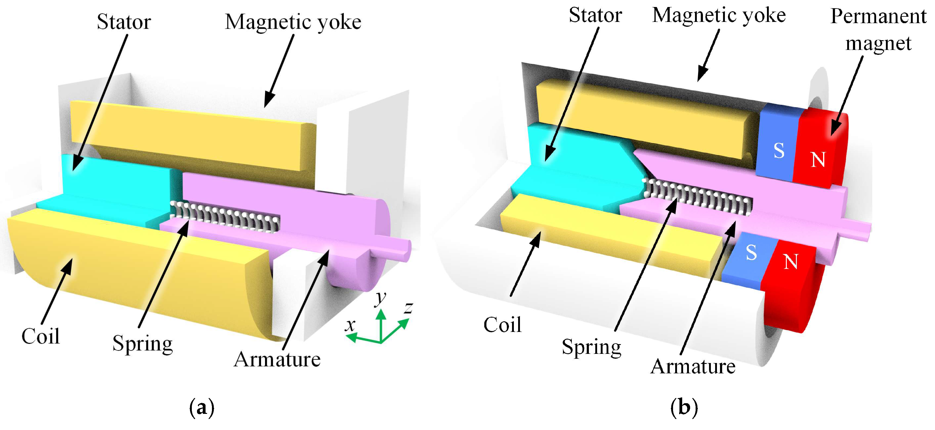
The original structure of the pneumatic microvalve’s electromagnet is shown in
Figure 1a. The electromagnet consists of a magnetic yoke, stator, armature, coil, and spring. Its operating principle is as follows: when the coil is energized, a magnetic field is generated, forming a closed loop through the magnetic yoke, stator, and armature. The resulting magnetic force overcomes the spring force, causing the armature to move inward. When the excitation is removed, the armature is pushed outward by the restoring force of the spring, corresponding to the opening and closing of the pneumatic valve. Since the magnetic yoke is formed by bending a sheet of magnetic conductive material, its radially asymmetric shape results in an asymmetric radial force acting on the armature during operation. This effect is particularly problematic in knitting machines, where fiber impurities may accumulate, further increasing the likelihood of armature sticking. Additionally, when the excitation is removed, the residual magnetic force caused by the inductance freewheeling effect prevents the armature from being immediately pushed outward by the spring, further delaying the valve’s response.
To eliminate the sticking phenomenon in the pneumatic electromagnetic microvalve and reduce the armature release time, this paper proposes a novel electromagnet structure, as shown in
Figure 1b. Without altering the existing coil and overall dimensions, three key modifications were made. First, the magnetic yoke was redesigned into a rotationally symmetric shape, eliminating the additional radial force acting on the armature. Second, a circular ring-shaped permanent magnet was added to the outer side of the armature to assist in rapidly pushing it out after the excitation is removed. Finally, the junction between the armature and the stator was modified into a double-inclined surface with asymmetric chamfers, ensuring line contact between the armature and the stator. This design causes the magnetic circuit to break rapidly when the armature undergoes slight displacement, facilitating a quicker release.
4. Finite Element Static and Transient Simulation of the Electromagnet
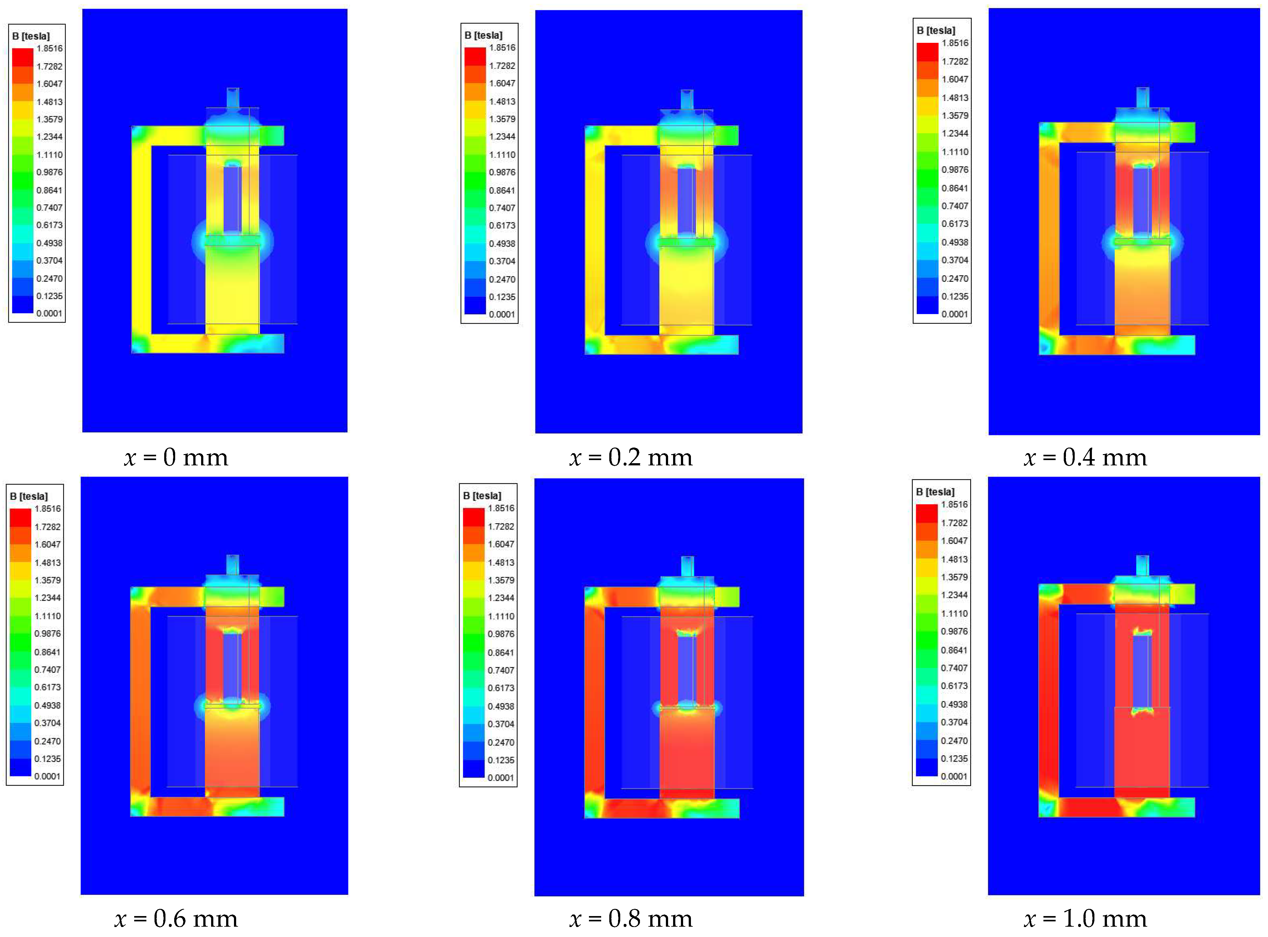
In the analysis of the magnetic field characteristics of the electromagnet, finite element analysis (FEA) is an effective and convenient method. Since the magnetic yoke of the original electromagnet lacks symmetry, using a two-dimensional model for simulation would introduce significant errors. Therefore, Maxwell (Ansys Inc., 2022) 3D is employed for finite element simulations. After importing the three-dimensional model, material properties were assigned to each component. The magnetic yoke, stator, and armature are made of DT4 soft magnetic material, and their magnetic behavior is modeled using a nonlinear B–H curve in the simulation. The permanent magnet is defined as NdFe52, with a relative permeability of 1.34 and an axial upward magnetization direction. These definitions ensure accurate representation of the magnetic properties and field distributions during excitation. The coil is configured as a stranded winding with a wire diameter of 0.1 mm, 5500 turns, a rated voltage of 24 V, and an internal resistance of 207 Ω. In the unenergized state, the armature is pushed to the outermost position by the spring force, where the maximum air gap is 1 mm. This position is defined as having an axial displacement of
x = 0 mm. As the armature engages, the axial displacement gradually moves toward 1 mm. Under different axial displacements, the magnetic flux density distribution of the electromagnet when the coil is energized at 24 V is shown in
Figure 2.
From the magnetic flux density distribution of the original structure, it can be observed that the maximum flux density reaches 1.85 T. High magnetic flux density is mainly concentrated in the left half of the magnetic yoke, the central and lower portions of the armature, and the stator region. At the sharp corners of the magnetic yoke, the flux density is significantly lower due to higher magnetic reluctance. Since the stator, armature, and left half of the magnetic yoke form a complete magnetic circuit, the right half of the magnetic yoke exhibits notably lower magnetic flux density, highlighting imbalanced magnetic flux distribution and substantial flux leakage in this structure. The force–displacement curves extracted for the armature are presented in
Figure 3a. It is observed that the initial electromagnetic force acting on the armature is approximately 5.35 N, exceeding the spring’s preload force of 1.62 N, and this force increases steadily with armature displacement, reaching a maximum of 35.8 N. Additionally, at different armature positions, the radial force in the Y-direction increases from 0.3 N to 1.7 N, while the radial force in the Z-direction rises from 0.13 N to 0.35 N. This phenomenon occurs because the magnetic yoke’s structural asymmetry is significantly greater along the Y-direction compared to the Z-direction, resulting in a larger radial force along the Y-direction, thereby increasing the likelihood of sticking in the pneumatic electromagnetic valve.
After analyzing the static magnetic characteristics of the original structure, the simulation type in Maxwell software was switched to transient analysis, and a spring force
was introduced into the armature motion equation as the load force. The transient response curve of the armature was obtained by applying a coil excitation voltage of 24 V between 0 and 25 ms and of 0 V between 25 and 100 ms, as shown in
Figure 3b. The coil current rose to 66 mA after 6 ms of applied excitation, at which point the armature started to move inward against the spring force and completed its motion by 9 ms. During this interval, the coil current decreased slightly due to the back electromotive force generated by the armature’s motion. After the armature completed its motion, the coil current continued to increase until it reached 115 mA at 25 ms. When the coil excitation switched to 0 V, the coil current rapidly decreased initially; however, due to the inductive freewheeling effect, the current decline slowed down significantly after 31 ms. It was not until 81 ms that the coil current decreased to 6.8 mA, at which point the armature began moving outward under spring force, finally reaching the outermost position at 83 ms. From the above analysis, it can be concluded that the original electromagnet has a pull-in time of 9 ms with an initial delay of 6 ms and a release time of 58 ms with a delay of 56 ms, indicating that the release time requires further optimization.
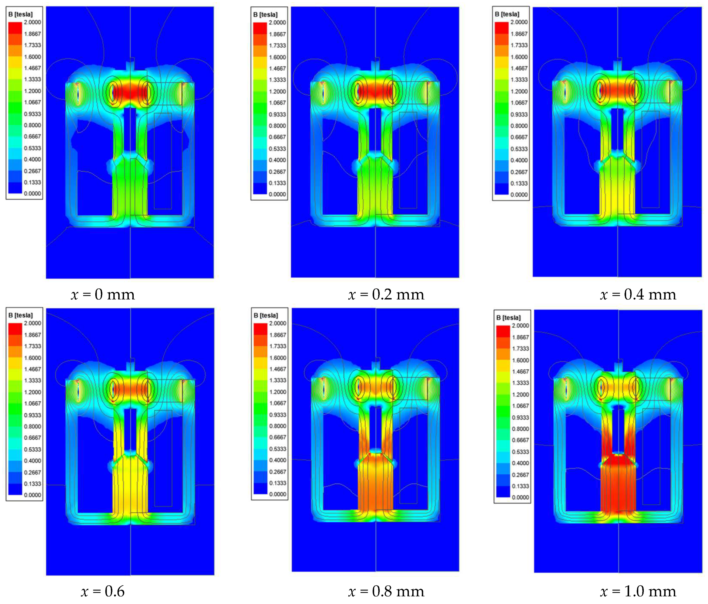
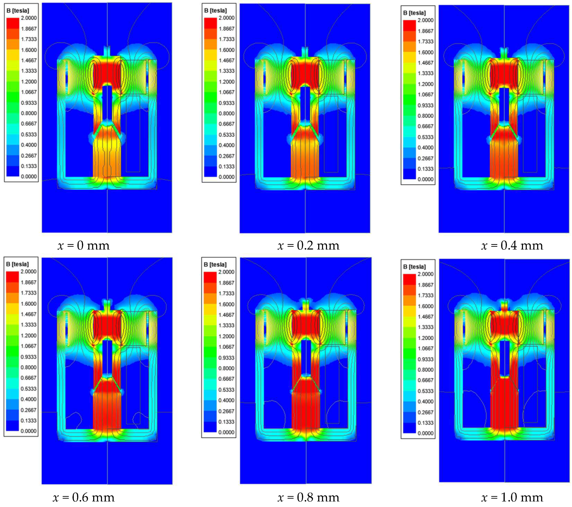
Without changing the coil parameters, the permanent magnet material was set to N52. Since the new structure is symmetric and facilitates subsequent optimization iterations, a two-dimensional model was used for simulation. Under different axial displacements, the magnetic flux density distribution of the new electromagnet structure under 24 V excitation is shown in
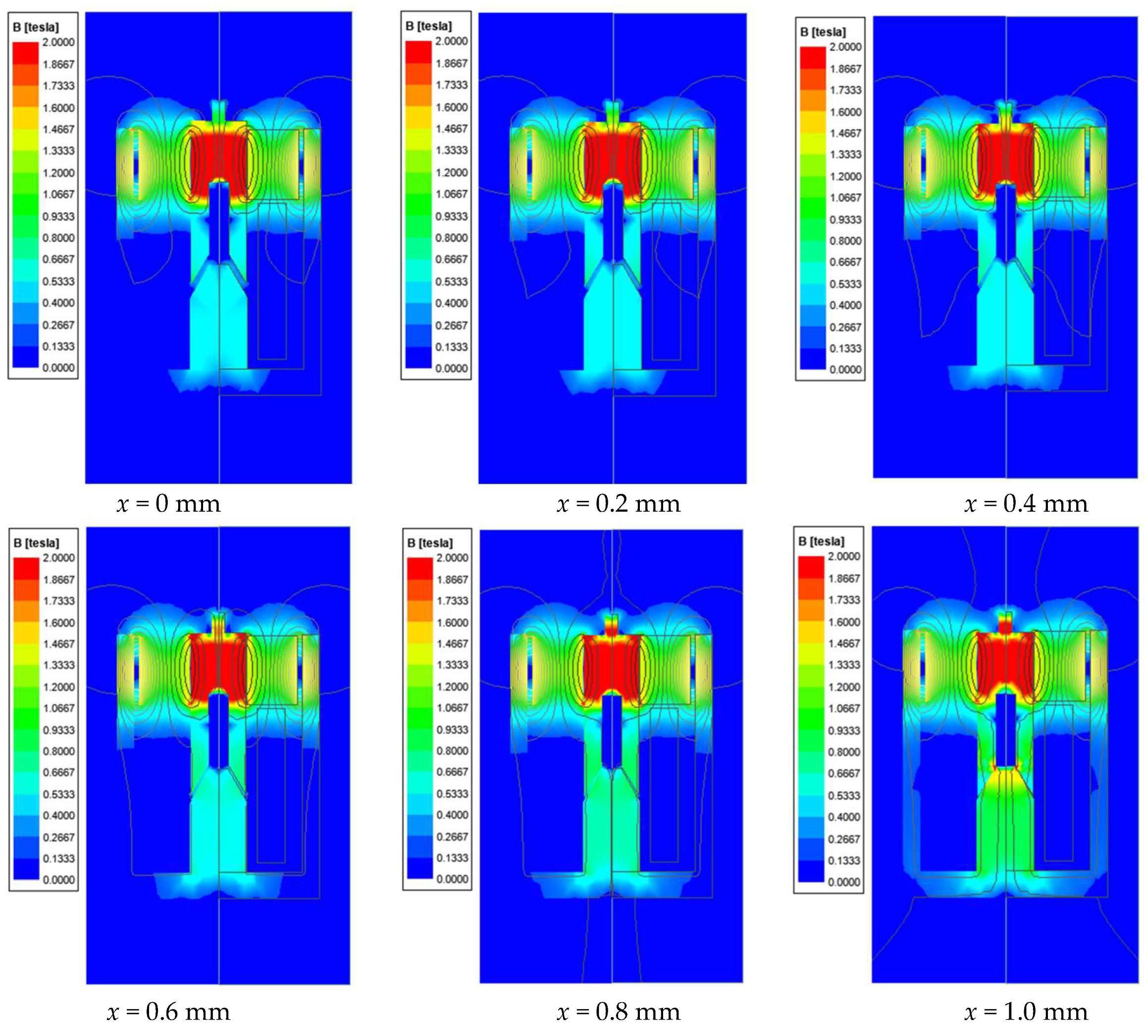
Figure 4, while the distribution under 0 V excitation is shown in
Figure 5. The magnetic field distribution is symmetrical, thus eliminating additional radial forces acting on the armature. Under 24 V excitation, the magnetic field generated by the coil merges with that of the permanent magnet and forms a closed magnetic circuit passing through the magnetic center of the magnet. As the axial displacement increases, the air gap at the pole shoe gradually narrows, enhancing the magnetic flux density in this region. Meanwhile, the flux density near the geometrical center of the permanent magnet, which corresponds to the central part of the armature, gradually decreases. This redistribution of the magnetic field results in a continuous increase in electromagnetic attraction, promoting upward armature motion. Under 0 V excitation, the magnetic field is only provided by the permanent magnet. The flux lines are mainly concentrated in the upper region of the armature, producing an upward magnetic force that assists the spring in releasing the armature, as shown in
Figure 5. This magnetic field orientation is opposite to that induced by the coil during energization, which helps to accelerate the dissipation of residual magnetism after de-energization. The passive force from the permanent magnet contributes to shortening the release delay and improving the dynamic response.
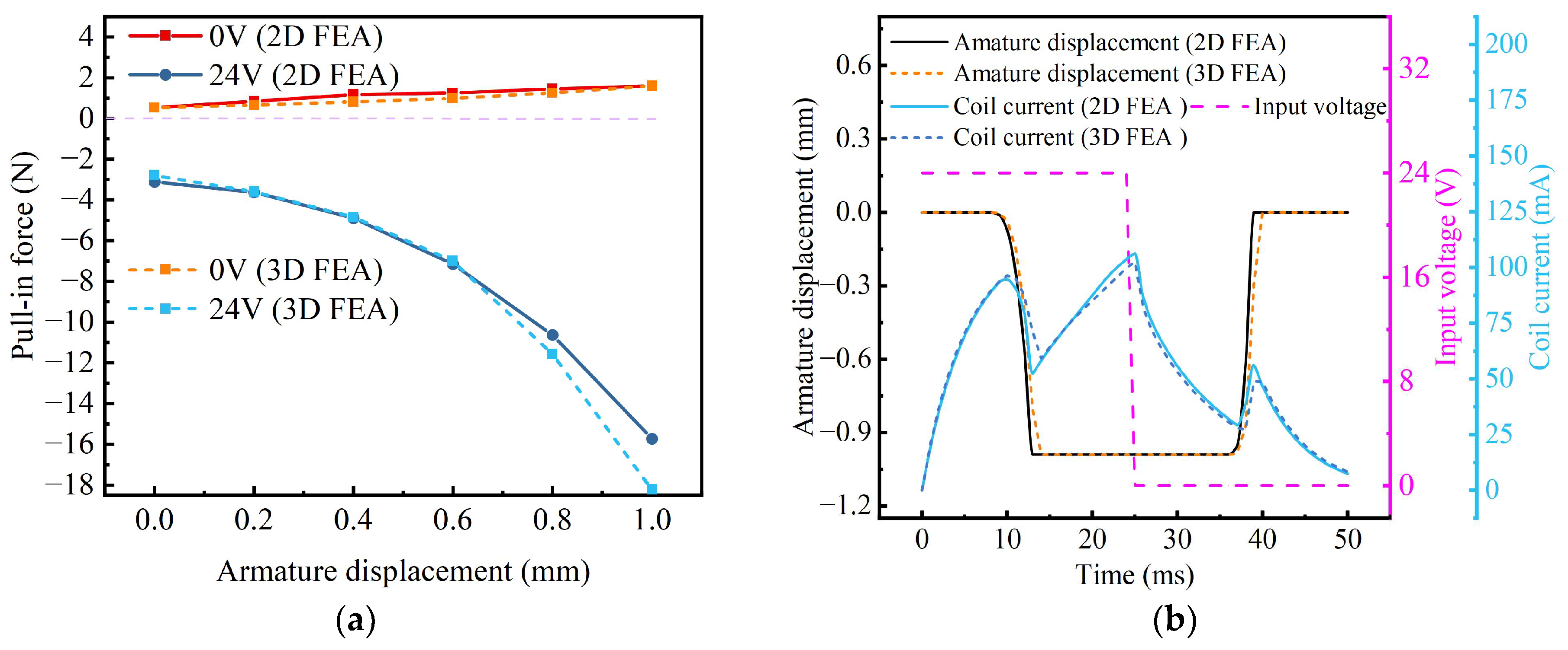
The force curves for the novel structure under different excitation conditions are presented in
Figure 6a. Under 24 V excitation, the initial electromagnetic force acting on the armature is approximately 3.1 N, exceeding the spring preload of 1.62 N, and increases gradually to a maximum of 15.7 N as displacement increases. Under 0 V excitation, the armature experiences an initial outward push force of 0.53 N at 0 mm displacement, rising gradually to a maximum of 1.6 N as displacement increases. Consequently, after removing excitation, the combined spring force and electromagnetic force acting on the armature is 1.62 + 0.9 × 1 + 1.6 = 4.12 N, representing a 63.5% increase compared to the original structure’s spring-only force of 1.62 + 0.9 × 1 = 2.52 N.
Given the same spring load force, the armature excitation was set to 24 V from 0 ms to 25 ms and switched to 0 V from 25 ms to 50 ms. Under these conditions, the transient response curve of the armature for the novel structure was obtained, as shown in
Figure 6b. It can be observed that 8 ms after applying the excitation, the coil current rose to 94 mA, causing the armature to overcome the spring force and start moving inward. The inward movement was completed at 13 ms, and during this movement, the coil current slightly decreased due to the back electromotive force induced by armature motion. After the armature reached its final position, the coil current continued to increase up to 106 mA at 25 ms, at which point the coil excitation was switched to 0 V, and the current began to rapidly decrease. Owing to the magnetic field generated by the permanent magnet neutralizing the coil’s residual magnetism, the slow-decay phase of coil current did not occur. By 36 ms, the coil current had decreased to 29 mA, at which point the armature began moving outward under the combined action of the spring and permanent magnet forces, finally reaching the outermost position at 39 ms. From this analysis, it can be concluded that the novel electromagnet structure achieves a pull-in time of 13 ms with a delay time of 8 ms and a release time of 14 ms with a delay time of 11 ms. Compared to the original structure, the novel structure reduces the release time by 75.9% and the delay time by 80%, while maintaining a similar pull-in time.
To further validate the reliability of the two-dimensional simulation approach adopted above, a comparative transient finite element analysis (FEA) was conducted between the 2D and 3D models of the novel structure. The results show that under 0 V excitation, the maximum difference in pull-out force between the 2D and 3D models is 0.26 N (26.7%), while under 24 V excitation, the maximum discrepancy in pull-in force is 2.51 N (13.7%). These deviations are primarily attributed to the inherent three-dimensional leakage flux paths introduced by geometric features such as the permanent magnet ring and off-axis chamfers, which cannot be fully captured in a 2D model. In terms of dynamic response, the 3D transient simulation yields a pull-in time of 14 ms and a release time of 15 ms, which differ by only 1 ms compared to the 2D model. These findings demonstrate that the two-dimensional simulation captures the key electromagnetic behavior of the novel symmetric structure with reasonable accuracy. Therefore, the subsequent multi-objective optimization was conducted based on the more computationally efficient 2D model.
5. Multi-Objective Optimization Algorithm Based on Structural Parameters of the Electromagnet
To further reduce the pull-in and release response times of the novel structure, a multi-objective algorithm was employed to optimize its geometric parameters. The optimization procedure is illustrated in
Figure 7. Initially, static magnetic simulations were conducted to optimize the magnetic force characteristics of the novel structure. The first optimization objective was the release thrust, defined as the armature force at an axial displacement of 1 mm under 0 V excitation; a larger release force ensures a faster armature release when the excitation is removed. The second objective was the electromagnetic attraction force at an axial displacement of 0 mm under 24 V excitation, where greater attraction force enables faster armature engagement. These two objectives are jointly maximized, as expressed in Equation (11). The NSGA-II algorithm combined with Maxwell simulations was utilized to perform iterative calculations within the geometric dimension constraints depicted in
Figure 8. Specific optimization parameter ranges are listed in
Table 1. The initial population was set to 50, and the number of iterations was set to 30. Constraint handling was performed using a rank-based penalty strategy, and the convergence was governed by a fixed generation limit. The fitness function adopted Pareto dominance to preserve solution diversity. The resulting Pareto front of the optimized static magnetic force curves is shown in
Figure 9. It can be observed that most solutions exhibit positive release forces, aligning with the spring force direction and thereby facilitating rapid armature disengagement. Furthermore, the initial attraction force must exceed 1.62 N to overcome the spring preload and ensure effective engagement of the electromagnet.
To further elucidate the influence of each geometric parameter on the two optimization objectives after the completion of the multi-objective evolutionary algorithm, a Pearson correlation-based sensitivity analysis was performed. This approach quantitatively reveals the linear relationship between individual design variables and the initial pull-in force, as well as the releasing thrust, thereby enabling a clearer understanding of their functional roles in the actuator’s performance. As shown in
Figure 10, k8, representing the height of the stator, exhibits a strong negative correlation with both pull-in and release forces. In contrast, k7, the inclined height of the stator, also shows a significant negative correlation with both targets, suggesting that a steeper stator slope tends to generate greater actuation forces. This can be attributed to the fact that a sharper inclination effectively increases the absolute contact area between the armature and the stator. In addition, k6, the radial width of the permanent magnet ring, is positively correlated with both objectives, indicating that a wider magnetic ring enhances the magnetic force acting on the armature, although it is constrained by the outer casing size. Interestingly, the remaining parameters (k1–k5) demonstrate opposing trends with respect to the two objectives, implying that their optimal values likely lie somewhere in the middle of their predefined ranges. These findings bridge the numerical sensitivity results with the geometric features of the actuator, offering guidance for subsequent structural refinement and performance enhancement.
Following the sensitivity analysis, the optimization results were further evaluated through transient simulations. After obtaining the Pareto front of the optimized static magnetic force curve, transient simulations were conducted for each design point, and the corresponding pull-in and release times were obtained, as shown in
Figure 11. To balance pull-in and release times, the selected design point corresponds to a pull-in time of 9.5 ms and a release time of 11.5 ms. Without changing the coil parameters and spring load, and with the permanent magnet material set to N52, the magnetic flux density distribution of the optimized electromagnet structure under 24 V excitation at different axial displacements is shown in
Figure 12, while the distribution under 0 V excitation is shown in
Figure 13. Compared to the pre-optimized structure, the magnetic flux density near the armature and pole shoes becomes significantly stronger under 24 V excitation. At small displacements, the magnetization is primarily concentrated in the regions near the contact surfaces of the armature and the pole shoes. As the axial displacement increases, the armature gradually approaches the pole shoe, resulting in both the armature and the pole shoe becoming fully magnetized. However, this leads to an increased upward magnetic force from the permanent magnet acting on the upper portion of the armature, which counteracts the downward coil-generated force. As a result, the net electromagnetic attraction becomes slightly weaker than that of the pre-optimized structure. Nevertheless, this attraction is still sufficient to achieve successful pull-in, since the primary optimization objective was to enhance release performance after de-energization. As shown in the flux density distribution under 0 V excitation in
Figure 13, the optimized permanent magnet configuration exhibits significantly improved magnetic penetration through the armature compared to the pre-optimized design. This results in a stronger upward magnetic force that assists the spring in releasing the armature more effectively. The enhanced magnetic circuit enables faster demagnetization of the coil’s residual field and contributes to shortening the release time.
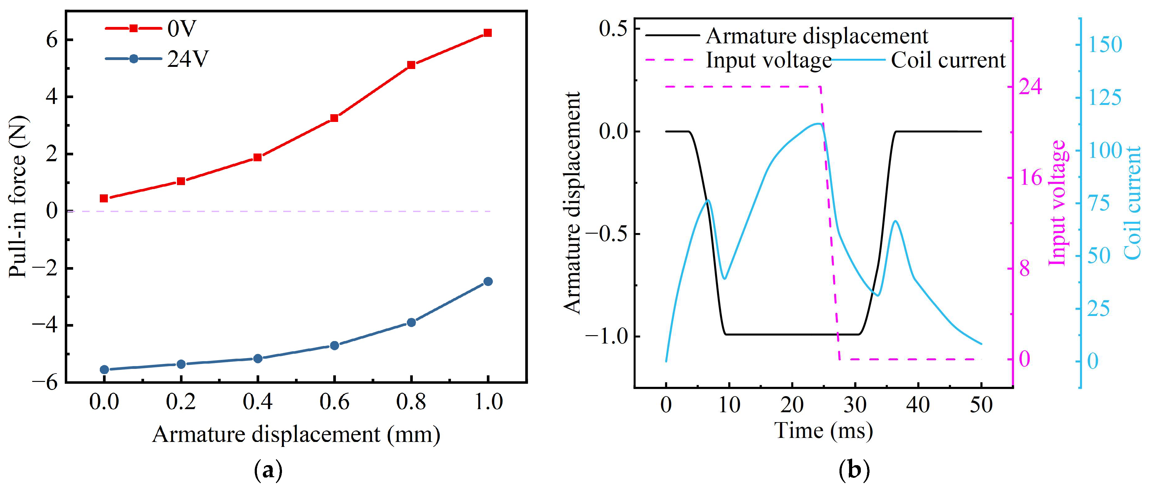
The force–displacement curves of the optimized armature under different excitations are shown in
Figure 14a. Under 24 V excitation, the initial attraction force on the armature is 5.5 N, which exceeds the spring preload of 1.62 N, and gradually decreases to 2.5 N as the armature displacement increases. Under 0 V excitation, the armature experiences an initial outward push force of 0.4 N at 0 mm displacement, reaching a maximum of 6.2 N as displacement increases. Consequently, after excitation removal, the combined force of the spring and electromagnetic thrust acting on the armature is 1.62 + 0.9 × 1 + 6.2 = 8.72 N, representing a 246% increase in thrust compared to the original structure, where the force was 1.62 + 0.9 × 1 = 2.52 N.
After analyzing the static magnetic characteristics of the optimized structure, the simulation type in Maxwell software was switched to transient analysis, and the spring force was introduced into the armature motion equation as the load force. The transient response curve of the armature was obtained by applying a coil excitation voltage of 24 V between 0 and 25 ms and of 0 V between 25 and 50 ms, as shown in
Figure 14b. It can be observed that 3.5 ms after the excitation was applied, the coil current rose to 76 mA, at which point the armature started moving inward against the spring force and completed its motion at 9.5 ms. During this interval, the coil current decreased slightly due to the back electromotive force generated by the armature’s motion. After the armature completed its motion, the coil current continued to increase until it reached 112 mA at 25 ms. When the coil excitation switched to 0 V, the coil current rapidly decreased initially; however, due to the permanent magnet’s magnetic field canceling out the residual coil magnetism, the slow-decay phase of the coil current did not occur. At 30.5 ms, the coil current dropped to 31 mA, at which point the armature began moving outward under the combined action of the spring and permanent magnet forces, finally reaching the outermost position at 36.5 ms. From the above analysis, it can be concluded that the optimized electromagnet structure achieves a pull-in time of 9.5 ms with a delay time of 3.5 ms and a release time of 11.5 ms with a delay time of 5.5 ms. Compared to the original structure, the optimized structure reduces the release time by 80.2% and the delay time by 90.2%, while maintaining a similar pull-in time. A comparative analysis of the response performance of different designs is shown in
Table 2, validating the effectiveness of the proposed novel structure and optimization algorithm.


