Abstract
With the application of tracked mobile robots in detection and rescue, how to improve their stability and trafficability has become the research focus. In order to improve the driving ability and trafficability of tracked mobile robots in rugged terrain, this paper proposes a new type of tracked mobile robot using passive suspension. By adding a connecting rod differential mechanism between the left and right track mechanisms, the contact stability between the track and terrain is enhanced. The kinematics model and attitude relationship of the suspension are analyzed and established, and the rationality of the passive suspension scheme is verified by dynamic simulation. The simulation results show that the tracked robot with passive suspension shows good obstacle surmounting performance, but there will be a heading deflection problem. Therefore, a track drive speed of the driving state compensation control is proposed based on the driving scene, which can effectively solve the problem of slip and heading deflection. Through the field test of the robot prototype, the effectiveness of the suspension scheme and control system is verified, which provides a useful reference for the scheme design and performance improvement of the tracked mobile robot in complex field scenes.
1. Introduction
In complex scenes such as planetary surface exploration, agricultural operations and disaster relief, mobile robots need to face soft and rugged terrain environments [1,2]. Such terrain greatly limits the trafficability and driving performance of mobile robot systems. Especially in soft terrain, conventional mobile robots such as wheeled robots are prone to fall into the ground, slip or lose traction [3,4]. The tracked mobile robot shows higher driving performance due to its large grounding area and excellent obstacle surmounting ability [5]. Tracked mobile robots have become an important transportation and bearing platform to deal with complex terrain.
Under complex terrain conditions, the attitude stability, traction performance and driving efficiency of tracked mobile robots still face severe challenges, which need to be optimized from multiple aspects, such as mechanism design and control strategy. In recent years, the research on the structural design and control strategy of tracked mobile robots has gradually developed [6]. In terms of structural design, Jeon et al. designed a track-type mobile robot based on a passive articulated suspension, which includes four tracks, two rockers, a differential gear and a main body [7]. Sun et al. developed a dual-arm mobile robot composed of a humanoid upper body and a tracked mobile platform to assist or replace humans in on-site rescue operations [8]. Li et al. designed a tracked mobile robot with bionic passive suspension [9]. The robot is constructed with a bionic animal limb structure, which has both load capacity and vibration isolation performance. Guo et al. introduced a tracked leg-type deformable robot to achieve all-terrain adaptation [10]. Luo et al. proposed a new type of reconfigurable tracked robot based on a four-link mechanism for complex terrain environments [11]. In terms of control, Chen et al. proposed a learning-based path tracking control strategy to solve the track skidding and body sinking of tracked mining vehicles in deep-sea mining systems [12]. Mitriakov et al. solved the problem of articulated tracked robot stair crossing based on reinforcement learning and carried out simulation and reality transfer [13]. Gianni et al. proposed an adaptive robust trajectory tracking controller design for active articulated tracked vehicles [14]. Cao et al. proposed a control scheme based on an extended state observer for trajectory tracking of tracked mobile robots affected by unknown external disturbances [15]. Shen et al. proposed a path planning and tracking control algorithm for mobile robot systems based on spatio-temporal conflicts and non-holographic constraints, which improves the control efficiency and accuracy of mobile robots [16]. Qi et al. developed a mobile robot control method that uses a fuzzy logic algorithm to consider the slip ratio of the wheel and its rate change, thereby enhancing the body traction and reducing energy consumption [17]. Silaa et al. proposed an indirect adaptive control of mobile robots based on a neural network and a discrete extended Kalman filter to improve the performance of robots in complex scenes [18].
The suspension system is a key component of the terrain adaptability of mobile robots. Most of the existing tracked robots use rigid suspension to connect the body and the track mechanism on both sides [6]. The rigid suspension has a simple structure and excellent impact resistance, but it has large body fluctuations and limited application in rugged and harsh scenes. In contrast, the passive suspension structure can effectively improve the grounding continuity of the robot in rough and soft terrain and enhance the traction and driving stability [19,20]. At present, passive suspension is widely used in the design of a planetary rover. Gao et al. proposed a necessary condition to correlate the degree of freedom of the passive suspension with the number of wheels of the all-wheel attachment property [21]. Lu et al. proposed a new wheeled rover, which combines the advantages of passive all-wheel connection and high-speed vibration reduction [22]. Zheng et al. proposed a wheeled stepping rover with improved active rocker bogie suspension, which can realize the switching between passive suspension and active suspension [23].
According to relevant research, passive suspension has application potential in improving the ground contact state of tracked mobile robots, improving terrain adaptability, and reducing body posture fluctuations [24]. However, there are few applications of passive suspension in tracked mobile robots. Therefore, this paper proposes a design scheme of a tracked mobile robot with a passive suspension structure and carries out modeling analysis and control research. The research in this paper can not only provide a design reference for the structure and control of the tracked mobile robot but also provide a reference for the analysis and prototype test of the robot in this study.
The rest of this paper is organized as follows: Section 2 introduces the design and prototype manufacturing of a tracked mobile robot with passive suspension. The establishment and analysis of the motion model of the tracked mobile robot are given in Section 3. In Section 4, the motion performance of the tracked robot during driving and obstacle surmounting is tested based on the simulation environment. In Section 5, the control system of the tracked robot is designed and developed. Finally, Section 6 summarizes this paper and looks forward to the future research direction.
2. Design of Tracked Mobile Robot
This section introduces the design of a tracked mobile robot with passive suspension and the principle of the mobile system. The specific parameters and communication line design of the tracked mobile robot prototype used in this study are also described.
2.1. Robot Mobile System
Most of the existing tracked mobile robots use rigid suspension, and both sides of the track mechanism are directly fixed on the vehicle body. The whole tracked mobile robot is a whole when driving. In order to improve the terrain adaptability and trafficability of the tracked mobile robot in rugged terrain, a tracked mobile robot with passive suspension is designed, as shown in Figure 1a. The left and right track mechanisms are connected to the body through the shaft and the differential mechanism. The differential mechanism is located at the front end of the body. As shown in Figure 1, when the tracked mobile robot is driving on a flat terrain, the left and right tracked mechanisms are parallel to the body, which is similar to a normal tracked mobile robot. When the track robot is traveling in rough terrain or crossing obstacles, one side of the track mechanism can adapt to the terrain ups and downs, while the other side of the track mechanism can still fully contact the ground. This shows that the tracked mobile robot using passive suspension can better guarantee the adhesion of the tracked mechanism on both sides to the terrain.
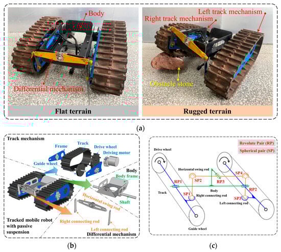
Figure 1.
Tracked mobile robot with passive suspension: (a) robot prototype; (b) robot structure; (c) schematic diagram of passive suspension structure.
The structure of the tracked mobile robot is shown in Figure 1b. The track mechanism on both sides is composed of track, frame, drive wheel, guide wheel and drive motor. And the center of the left and right track mechanisms is installed on the shaft of the body frame. The track mechanism can rotate around the body shaft. The differential mechanism in the front of the body is composed of the left connecting rod, the right connecting rod and the horizontal swing rod. The two ends of the left and right connecting rods are connected to the track mechanism and the horizontal swing rod, respectively. The horizontal swing rod is installed on the vehicle body and can rotate around the center.
According to the structural analysis of the tracked mobile robot, the schematic diagram of its passive suspension is shown in Figure 1c. The mechanism of the whole mobile system mainly includes three revolute pairs and four spherical pairs. The revolute pairs are located in the body-left track mechanism, the body-right track mechanism, and the body-horizontal swing rod. The spherical pairs are located in the left track mechanism-left connecting rod, the left connecting rod-horizontal swing rod, the horizontal swing rod-right connecting rod, and the right connecting rod-right track mechanism. When the body is fixed, the rotation state of the track mechanisms on the left and right sides can be analyzed. When the front end of the right track mechanism is lifted, RP1 rotates and drives the right connecting rod at SP1 to move upward. At this time, the right connecting rod drives the horizontal swing rod to rotate clockwise around RP3 through SP2. SP4 moves downward, and the left connecting rod presses SP3 downward. It causes the front end of the left track structure to press down and rotate around RP2. This shows that the suspension scheme of the mobile system can effectively maintain the angle relationship between the track mechanism and the body on both sides while passively adapting to the terrain.
2.2. Communication Line
The parameters of the tracked mobile robot prototype used in this study are shown in Table 1. In practical engineering applications, the parameters of the tracked mobile robot can be adjusted according to the requirements, and the required equipment and sensors can be installed on the tracked robot body. In this study, the angle rotation of the tracked mobile robot and the track mechanism on both sides is limited to 40° in order to prevent the tracked mobile robot from overturning itself when adapting to the terrain. The robot prototype is independently powered by a DC power supply.

Table 1.
Prototype parameters of tracked mobile robot.
The communication circuit of the tracked mobile robot prototype is shown in Figure 2. The 24 V DC battery supplies power to the left drive motor, the right drive motor and the industrial personal computer. In addition, a power sensor is used to detect the real-time circuit and voltage of the drive motor. The industrial personal computer sends control commands to the pulse output module through the Usb-CAN module to control the forward and steering of the tracked mobile robot. The pulse output module sends the PWM signal to the motor drive module to control the rotation direction and speed of the drive motor. At the same time, according to the actual engineering requirements, various external sensors such as inertial measurement units, vibration sensors, etc. can be installed, and the collected data can be sent to the industrial personal computer for recording and analysis in real time through the line.
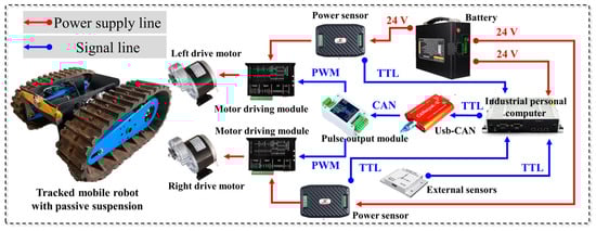
Figure 2.
Communication line of tracked mobile robot.
3. Robot Motion Analysis
In order to better analyze the motion state of the tracked mobile robot, this section analyzes the mobile kinematics of the robot. Meanwhile, the relationship between the suspension angle change and the track–ground force of the tracked mobile robot is also established in this section.
3.1. Kinematics of Movement
According to the driving scene and state of the tracked mobile robot, its motion diagram on the two-dimensional plane is shown in Figure 3a. The overall position and attitude of the tracked mobile robot can be defined as
where is the heading angle of the robot. According to the moving state of the tracked mobile robot, its forward speed can be defined as , and the overall rotation angular velocity is . The kinematic relationship between the position and attitude of the robot is
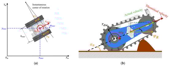
Figure 3.
Kinematics of tracked mobile robot: (a) schematic diagram of motion on two-dimensional plane; (b) side view diagram.
The tracked mobile robot is driven by the track mechanism on both sides. According to the steering relationship of the robot, the speed relationship between the left and right tracks and the body is
where are the speeds of the left and right track mechanisms, respectively. is the width between the two sides of the track mechanism.
Due to the use of passive suspension, the tracked mobile robot will have a certain angle between the track mechanism on both sides and the horizontal ground when driving in rough terrain. Figure 3b is the diagram on the right side. is the track–ground contact angle of the right track mechanism. Considering the contact angle and slip between the track and the ground, the relationship between the track plane velocity and the angular velocity of the left drive motor and the angular velocity of the right drive motor is
where are the theoretical speed and actual speed of the track mechanism, respectively. is the radius of the driving wheel. s is the slip rate of the track.
The relationship between the vehicle state of the tracked mobile robot and the output of the drive motor can be obtained by sorting out Equations (1)–(5):
is the coefficient matrix containing the track slip rate and the track–ground contact angle obtained by sorting the equations.
3.2. Suspension Posture
According to the moving state of the tracked mobile robot, the roll angle, pitch angle and yaw angle of the body posture can be defined as
Figure 4 is the suspension attitude diagram of the tracked mobile robot. Since the track mechanism on both sides only rotates around the body shaft, the attitude of the suspension mechanism on both sides can be expressed as
where are the relative angles between the track mechanism and the body on both sides. According to the motion relationship of such a multi-link mechanism calculation [24], the angle relationship is
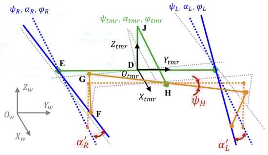
Figure 4.
Suspension posture diagram of tracked mobile robot.
According to the mechanical motion calculation in [24], the relative angles between the two sides of the track mechanism and the body are almost equal and opposite. Therefore, the sum of the pitch angles of the track mechanism on both sides is about twice the pitch angle of the body in the world coordinate system. It can be seen that only collecting the pitch angle of the body cannot obtain the angle of the track mechanism on both sides. Therefore, this study uses real-time acquisition of the angle of the horizontal swing rod relative to the body to calculate the attitude of the track mechanism. According to Figure 4, in the robot body coordinate system, the coordinates of each motion pair can be expressed as
Because the length of each connecting rod of the suspension is known, the coordinates of G and F should satisfy the following: the modulus of vector is equal to the length of the left connecting rod .
By sorting out the Equations (9)–(12), the angle calculation can be obtained:
3.3. Track–Ground Force Analysis
When the tracked mobile robot travels on soft ground, the normal stress and tangential stress will be generated between the track and the ground, as shown in Figure 5. According to the theory of terramechanics [25,26], stress can be expressed as
where , , n, c, are cohesive modulus, friction modulus, topographic deformation index, cohesion coefficient and friction angle. is the width of the track, and z is the subsidence of the track. K is the shear deformation modulus, and j is the shear displacement.
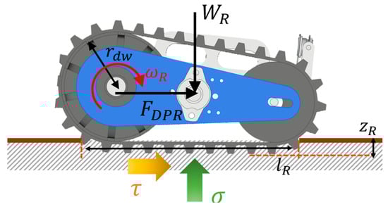
Figure 5.
Force analysis of track–soft ground.
Assuming that the crawler load is evenly distributed, the subsidence of the track mechanism can be expressed as
where is the contact length between the track and the ground. According to the shear stress relationship, the drawbar pull that the track can provide can be expressed as
When the track mechanism is driving on hard ground, its traction state can be simply expressed by the friction coefficient between the track and the ground:
4. Dynamics Simulation of Tracked Mobile Robot
In order to verify the driving effect and characteristics of the tracked mobile robot with passive suspension, a dynamic simulation test is carried out. In this section, the simulation results of tracked mobile robots without passive suspension and with passive suspension are introduced and compared.
4.1. Tracked Mobile Robot Without Passive Suspension
Figure 6a is the simulation setting of the tracked mobile robot without passive suspension. The dynamic simulation of this study was tested and analyzed in the dynamic software ADAMS (2020). In the simulation, the track moving structure of the tracked mobile robot, the motion pair between the vehicle body and the differential mechanism are all set as fixed pairs to ensure that the whole suspension is a rigid suspension used by the conventional tracked mobile robot. In order to test the obstacle surmounting performance of the tracked mobile robot, a trapezoidal obstacle stone is set in front of the right tracked mechanism. The height of the obstacle stone is 5 cm, and the angle between the trapezoidal side and the horizontal plane is 45°. In the simulation, the same speed drive method is used to control the tracked mobile robot to drive in a straight line, and the speed of the left and right track drive motors is set to 80°/s. This is currently the most commonly used driving method for tracked mobile robots in straight-line driving.
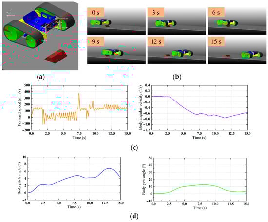
Figure 6.
Simulation of tracked mobile robot without passive suspension: (a) simulation settings; (b) moving process; (c) vehicle motion state; (d) body posture.
Figure 6b is the driving process of a tracked mobile robot that is not suitable for passive suspension. The attitude of the tracked mobile robot changes as a whole during the obstacle crossing process. When the right track mechanism crosses the obstacle, the left track mechanism also tilts. Figure 6c shows the motion state of the tracked mobile robot during driving. The average driving speed of the robot is 99.1 mm/s, and the average vehicle slip rate is 21.1%. The tracked robot has a significant speed drop at 1.7 s–7.1 s, indicating that the robot has received obstacles during the obstacle crossing process. This period lasted 5.4 s. During the driving process, the average rotation angular velocity of the robot body is 0.46°/s, and the maximum is 0.76°/s. By comparing the driving process, it can be seen that the body angular velocity deviation begins in the obstacle crossing stage. Figure 6d is the change in body posture during the robot driving. In this process, the maximum pitch angle of the body is 6.8°, and the average pitch angle is 3.9°. The maximum yaw angle of the body is 12.8°, and the final yaw angle is 4.0°. This shows that the obstacle crossing will significantly cause the body posture change of the tracked mobile robot and cause the robot to yaw.
4.2. Tracked Mobile Robot with Passive Suspension
Figure 7a is the simulation setting of the tracked mobile robot with passive suspension. The revolute joint and spherical joint are set according to the design principle between the body, the track mechanism and the differential mechanism of the tracked mobile robot. The obstacle setting and motor drive of the simulation are the same as those of the tracked mobile robot, which is not suitable for passive suspension. Figure 7b shows the driving process of a tracked mobile robot with passive suspension. During the obstacle crossing process of the tracked mobile robot, both sides of the tracked mechanism can have good contact with the ground. When crossing the obstacle, the angle change of the right track mechanism drives the connecting rod of the differential mechanism to rotate and tilt. The left track mechanism is in full contact with the ground, and the body and the left and right track mechanisms maintain a stable angle relationship.
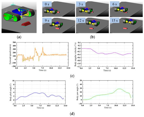
Figure 7.
Simulation of tracked mobile robot with passive suspension: (a) simulation settings; (b) moving process; (c) vehicle motion state; (d) body posture.
Figure 7c is the motion state of the whole vehicle in the driving of the tracked mobile robot. The average driving speed of the robot is 115.5 mm/s, and the average vehicle slip rate is 8.1%. The tracked robot showed a significant speed drop at 1.7 s–5.0 s, which lasted for 3.3 s. The average body rotation angular velocity of the robot is 0.26°/s, and the maximum is 0.44°/s. It can be seen that compared with the tracked mobile robot without passive suspension, the average slip rate of the robot is reduced by about 13%, the obstacle crossing time is shortened by 2.1 s, and the average rotation angular velocity of the body is reduced by about 0.20°/s. This shows that the use of passive suspension can better improve the terrain adaptability of the tracked mobile robot and can better reduce the conflict between the rugged terrain and the crawler mechanism on both sides. This is beneficial to improve the trafficability and driving performance of tracked mobile people in complex and rugged terrain, which is also in line with the design purpose and concept of this study.
Figure 7d is the change in body posture during the robot driving. In this process, the maximum pitch angle of the body is 3.8°, and the average pitch angle is 2.3°. The maximum yaw angle of the body is 28.4°, and the final yaw angle is 4.5°. The use of passive suspension reduces the maximum pitch angle of the body by 3°. This shows that the use of passive suspension can reduce the body pitch attitude change and improve the stability of the body when the tracked mobile robot is driving in rugged terrain. However, the yaw angle of the tracked mobile robot with passive suspension becomes larger during the test. Through the analysis of the experimental phenomena, this phenomenon is considered to be due to the use of passive suspension, which makes the difference between the track–ground contact angle of the track mechanism on the left and right sides more obvious. This leads to an increase in the difference in the horizontal driving speed of the tracks on both sides, which in turn causes the body deflection phenomenon. This problem can be solved by compensating for the driving speed of the track on both sides [20].
5. Control System Design
In order to realize the conventional mobile driving of the tracked mobile robot and improve the driving performance and effect of the tracked mobile robot, in this section, the controller control system is designed and developed, and the control signal transmission and track drive speed control are introduced, respectively.
5.1. Control Signal Transmission
On the basis of the hardware conditions of the tracked mobile robot and the sensing information required for control, the control signal transmission line of the tracked mobile robot is built, as shown in Figure 8. In order to obtain the real-time driving state of the robot system, an inertial measurement unit is installed at the geometric center of the vehicle body. The inertial measurement unit is used to collect the forward speed and body rotation angular velocity of the tracked mobile robot in real time. At the same time, the posture of the robot body is collected, including pitch angle , roll angle and yaw angle . In order to analyze and calculate the attitude state and change of the passive suspension of the robot, according to Equation (13), an angle sensor needs to be installed on the horizontal swing rod of the differential mechanism to collect the angle of the horizontal swing rod in real time.
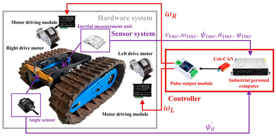
Figure 8.
Control signal transmission of tracked mobile robot.
All sensor data will be transmitted to the industrial computer for recording and analysis. At the same time, all control algorithms, including track speed control, will be deployed in the industrial computer for real-time calculation and output. After obtaining the corresponding sensor data, the industrial computer will process and calculate the algorithm. Finally, the speed commands and are generated to the left drive motor and the right drive motor through the pulse output module. When the tracked mobile robot travels according to the planned path, the expected forward speed and body rotation angular velocity will be generated by the external master controller or the path planning degree of the industrial computer.
5.2. Drive Speed Control of Track
According to the analysis of the theory and simulation results of the tracked mobile robot, it can be concluded that the tracked mobile robot using passive suspension has the following characteristics and control problems when driving on rough terrain:
- (1)
- The slip of the tracked mobile robot and the change of the track–ground contact angle will affect the robot’s tracking of the desired driving state and trajectory.
- (2)
- The tracked mobile robot will have a more obvious course deviation phenomenon when crossing the obstacle. This problem is not significant when the obstacle is not crossed or when driving on flat terrain.
- (3)
- The tracked mobile robot will be hindered by the terrain when crossing obstacles.
- (4)
- The forward speed control and body speed control of the tracked mobile robot are coupled together, and it is difficult to control them accurately at the same time.
Based on the above driving problems and characteristics of the tracked mobile robot, this study proposes a tracked driving speed control based on vehicle driving state control and based on the driving scene in order to improve its driving performance. Figure 9a is the overall principle flow chart of the control algorithm. It mainly includes the following control contents and steps:
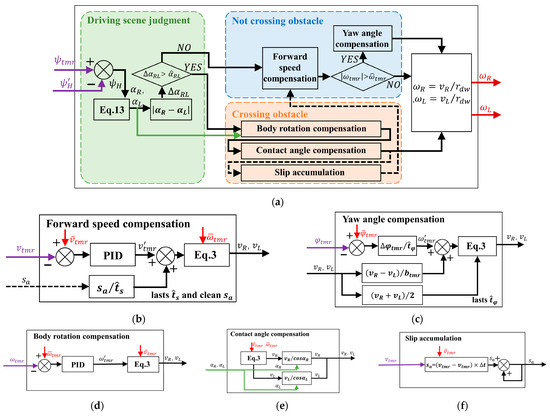
Figure 9.
Track speed control algorithm schematic diagram: (a) overall principle flow chart; (b) forward speed control; (c) yaw angle control; (d) contact angle control; (e) body rotation control; (f) slip accumulation.
- (1)
- Firstly, according to the attitude of the passive suspension, the driving scene of the tracked mobile robot is judged, and the current driving scene of the robot is divided into two kinds: not crossing the obstacle and crossing the obstacle.
- (2)
- When the tracked mobile robot is not crossing the obstacle, the forward speed of the robot is compensated as shown in Figure 9b, and the steering angular velocity state of the robot is monitored. When an abnormal accidental deflection occurs, additional yaw angle control is performed on the robot to avoid the tracked mobile robot from deviating too much from the desired driving trajectory, as shown in Figure 9c.
- (3)
- When the tracked mobile robot is crossing the obstacle, the real-time calculation of the robot’s track–ground contact angle change and the track speed control are carried out, and the robot’s body steering angular velocity is compensated in real time. At the same time, the slip generated by the robot during the obstacle-crossing process is accumulated, and the slip control is performed after the robot ends the obstacle-crossing process and enters the flat terrain.
The tracked speed control method fully considers the driving state and problems of the tracked mobile robot using passive suspension in various scenarios. The forward speed of the tracked mobile robot and the angular velocity of the body are tracked separately. On the one hand, it can avoid the coupling effect of the two to bring certain difficulty and control fluctuation to the control. On the other hand, this can reduce the real-time computation of the controller. In addition, an additional control algorithm is also set up to avoid the problem of untimely control of the tracked mobile robot caused by the separation of forward speed and body rotation control in this controller. The first is the accidental deflection detection and control when the obstacle is not crossed. The second is to perform slip accumulation during obstacle crossing and delay control after obstacle crossing contact. The reason why there is no real-time control for slip when crossing the obstacle is that the slip control needs to improve the speed of the tracked mobile robot. Increasing the speed of the tracked mobile robot during obstacle crossing will increase the impact on the ground, which is likely to cause damage to the robot structure or rollover.
In order to realize the above track speed control method and function, the algorithm calculation used in this study is shown in Figure 9b–f. In the controller, the pitch angles of the left and right track mechanisms are calculated in real time according to the body roll angle and the horizontal swing rod angle . When the angle between the left and right tracks exceeds the set judgment angle , it indicates that the tracked mobile robot is driving on the rugged terrain, and the current state is judged to be crossing an obstacle. On the contrary, it is judged that the robot is currently in a not-crossing-obstacle state.
When the tracked mobile robot is in a not-crossing-obstacle state, real-time tracking control is first performed according to the current forward speed and expected forward speed of the tracked mobile robot. If there is a cumulative slip at the last obstacle crossing, the cumulative slip should be compensated in seconds. Then, according to Equation (3), the speed of the left and right track mechanisms is calculated. Then, the rotation angular velocity of the robot body is compared with the set angular velocity range . If it is less than the set value, it indicates that there is no accidental deflection, and the speed of the left and right crawler mechanisms is calculated as the speed of the left and right drive motors for output control. If the body angular velocity exceeds the rated value, the robot is judged to have an accidental deflection. At this time, the yaw angle of the body is interpolated with the expected angle , and the compensation is performed in seconds. Then, the speeds of the left and right track mechanisms are recalculated, and the output control is carried out.
When the tracked mobile robot is in the obstacle crossing state, the real-time tracking control is carried out according to the current body rotation angular velocity and the expected angular velocity of the tracked mobile robot, and the speeds of the left and right track mechanisms are calculated. Then, according to the angle between the left and right track mechanisms , the speed command of the track mechanism on both sides is compensated and calculated, and the track speed command, considering the angle between the track and the ground, is obtained. Then, the speeds of the left and right track mechanisms are calculated as the speeds of the left and right drive motors for output control. In this process, according to the difference between the current forward speed and the expected forward speed of the tracked mobile robot, the cumulative slip calculation of the obstacle crossing process is carried out.
6. Tracked Mobile Robot Test
In order to test the driving performance and control effect of the tracked mobile robot, this section introduces the test results and analysis of the conventional mobile test and control system of the robot prototype.
6.1. Test Settings
In order to test the driving effect and performance of the tracked mobile robot with passive suspension in rugged terrain, the prototype test was carried out in the indoor soil bin built by the terramechanics research group of Jilin University. The JLU Mars series of simulated Martian soil is mainly laid in the test site. The mechanical parameters of the simulated Martian soil are all calibrated [27].
The conventional mobile test is to test the conventional mobility performance and suspension effect of the tracked mobile robot using passive suspension. It is mainly noted that the tracked mobile robot is only subjected to conventional linear and differential steering motion control in the conventional mobile test, and the tracked drive control algorithm developed in Section 5.2 is not used. In the conventional mobile test, slate and extremely rugged terrain were arranged in the test site in order to simulate the rugged terrain scene. The edge height of the slate obstacle is 3 cm, and the upper surface is relatively flat. The edge height of the extremely rugged terrain is 6 cm, and there are many protruding sharp stones on the upper surface. In the experiment, considering the load and center distribution of the tracked mobile robot prototype, the driving mode of the driving wheel on the front side is adopted. The theoretical forward speed of the tracked mobile robot is set to 25 cm/s, and the control parameters are generated for the drive motor according to the steering state of the robot. The test time is 45 s.
The control system test is to test the effect and performance of the track drive control algorithm of the tracked mobile robot developed in Section 5.2. In the control system test, according to the test scene in the robot simulation, two sets of slate obstacles are placed at intervals in front of the right track moving mechanism of the tracked mobile robot. The slate barrier is a two-layer slate with an edge height of 6 cm. This obstacle distribution can better test the obstacle crossing state and existing problems of the tracked mobile robot prototype. In the experiment, the tracked mobile robot is set in a straight-line driving state, and the angular velocity of the driving motor is 160°/s. The test time is 10 s. The test is divided into the test scene of the tracked mobile robot using the control system and the test scene without the control system, and the test results are compared. In the experiment, the acquisition and control frequency of the control system is set to 10 Hz.
6.2. Conventional Mobile Test
Figure 10 shows the conventional moving test results of a tracked mobile robot prototype with passive suspension. Figure 10a is the test scenario and test process. The prototype of the tracked mobile robot is first driven on JLU Mars 3 simulated Martian soil, which is extremely rugged terrain. The robot successfully crossed the extremely rugged terrain and climbed down from the edge of the terrain to JLU Mars 1 simulated Martian soil. The robot continued to move forward through the slate obstacle to return to the initial position. It can be seen that the tracked mobile robot with passive suspension can maintain a good driving state and vehicle subsidence in flat and soft terrain, and there will be no significant rotation or subsidence trapped. The driving performance of tracked mobile robots using passive suspensions on rugged rocks is very beneficial. During the driving process, the suspension mechanism on both sides can maintain good contact with the ground according to the terrain fluctuation and avoid the phenomenon of the track mechanism vacating. The track mechanism can maintain a good angle relationship with the body. When the robot climbs up the rugged terrain, the effect of the passive suspension is very significant, as shown in Figure 10a when the driving time is 5 s. The tracked mobile robot has a certain angle with the edge of the terrain, so that the right tracked mobile mechanism first contacts and climbs. Due to the use of passive suspension, the right crawler moving mechanism can be lifted and climbed first. This avoids the phenomenon of driving obstruction or climbing failure caused by the angle between the crawler mechanism on both sides and the edge of the terrain.
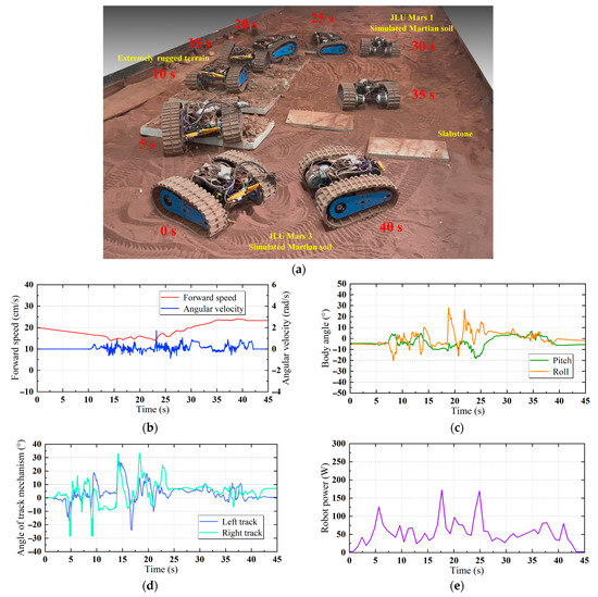
Figure 10.
Conventional mobile test of tracked mobile robot: (a) test process; (b) driving state; (c) body posture; (d) track mechanism angle; (e) energy consumption.
Figure 10b shows the driving state during the test. The average forward speed of the robot during the whole driving process is 19.1 cm/s, and the average slip rate is 23.6%. However, the average slip rate of the tracked mobile robot in flat soil terrain is about 4.8%, and the average slip rate in extremely rugged terrain can reach 36.1%. This shows that the tracked mobile robot is more hindered when driving on rough terrain. At the same time, it can also be seen that the rotation angular velocity of the robot body changes more violently when driving in rugged terrain, and the maximum angular velocity can reach 1.73 rad/s. This shows that it is important to maintain the driving state of the tracked mobile robot in rugged terrain. Figure 10c shows the body posture of the tracked mobile robot during the test. Figure 10d is the angle change of the track mechanism on both sides. During the driving process, the posture of the robot body is relatively stable, with an average pitch angle of 2.1° and an average roll angle of 3.5°. In rugged terrain, the angle of both sides of the track mechanism changes sharply because of the need to adapt to the terrain. The maximum angle of the right track mechanism is 33.2°, and the maximum angle of the left track mechanism is 27.9°. Therefore, in order to avoid the vehicle overturning due to the excessive change in the track angle, it is necessary to set the rotation limit of the track mechanism. Figure 10e shows the energy consumption of the tracked mobile robot in the conventional mobile test. The average power of the whole test process of the robot is 53.8 W, and the maximum power is 172.5 W, which occurs in the rough terrain.
According to the above test results and analysis, it can be seen that the tracked mobile robot with passive suspension has a better driving effect on complex and rugged terrain. The robot shows good obstacle crossing performance and trafficability, and it can maintain good track–ground contact with rugged terrain. When driving on soft soil terrain, the robot can also drive stably. However, it should be noted that when the tracked mobile robot is driving in rugged terrain, the driving state and body posture are greatly affected, and the energy consumption will also increase. It is necessary to detect the driving state of the tracked mobile robot in real time and make timely control adjustments to avoid accidents.
6.3. Control System Test
Figure 11 and Table 2 are the test results of the control system of the tracked mobile robot prototype with passive suspension. Figure 11a is the test scenario and test process. According to the test process, it can be seen that without the use of the control system, the body of the tracked mobile robot has obvious deflection after crossing the right track mechanism on both sides. The tracked mobile robot deviates from the driving trajectory and even finally encounters the edge of the site. This is necessary to avoid autonomous operation of tracked mobile robots in the field, and it is easy for the robot to travel to dangerous areas. At the same time, due to the slip and obstruction during the driving process, the robot also failed to reach the desired target position. Without using the control system, the slip rate of the tracked mobile robot prototype is about 12.9% during the whole test process. It can be seen from the figure that the slip and heading deflection phenomena during the test of the tracked mobile robot have been improved after using the control system. During the whole test process, the average slip rate of the robot is reduced to 7.1%. The body heading of the robot is also controlled and corrected in time during the test.
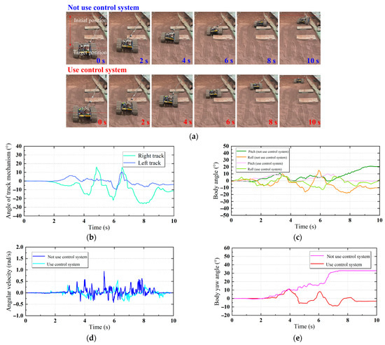
Figure 11.
Control system test of tracked mobile robot: (a) test process; (b) track mechanism angle (not using control system); (c) body posture; (d) body rotation angular velocity; (e) heading deflection.
Table 2.
Moving state of tracked mobile robot in the control system test.
Figure 11b shows the angle change of the track mechanism on both sides. During the test, the maximum angle of the right crawler mechanism is 15.9°, and the maximum angle of the left track mechanism is 10.4°. Figure 11c is the body posture of the tracked mobile robot during the test. In the scene without the control system, the average pitch angle of the robot body is 6.5°, and the average roll angle is 10.9°. In the scene using the control system, the average pitch angle of the tracked mobile robot body is 1.3°, and the average roll angle is 1.8°. This shows that the use of the control system makes the robot more stable in driving. This is mainly because the control system compensates the contact angle coordinately when the tracked mobile robot crosses the obstacle. This will make the impact of the terrain and the track properly reduced, thereby enhancing the stability of the body posture. Figure 11d is the rotation angular velocity of the tracked mobile robot during the test. Figure 11e is the heading deflection of the robot during driving. Without the use of the control system, the maximum body angular velocity of the tracked mobile robot during the test is 0.94 rad/s, the maximum yaw angle is 16.6°, and the final yaw angle is 33.0°. When using the control system, the maximum angular velocity of the robot body is only 0.55 rad/s, the maximum yaw angle is 11.0°, and the final yaw angle is only 2.9°. This shows that the control system has a good effect on maintaining the heading of the tracked mobile robot.
According to the above test results and analysis, it can be seen that the use of the control system can effectively summarize the slip and yaw phenomena of the tracked mobile robot using passive suspension. It can effectively improve the performance of a tracked mobile robot in driving. At the same time, in the actual engineering application, the control system can be further adjusted and upgraded according to the engineering requirements and hardware system, so that it has more diverse and excellent performance.
7. Conclusions and Future Work
In this paper, a new type of tracked mobile robot using passive suspension is proposed, and its application in rugged terrain is studied. The passive terrain adaptability of the tracked mobile robot is enhanced by adding a connecting rod differential mechanism between the left and right track mechanisms and the body. At the same time, the kinematics model and suspension attitude relationship of the tracked mobile robot using passive suspension are analyzed and modeled. In order to verify the application effect of passive suspension in a tracked mobile robot, the dynamic simulation of the robot is carried out to verify the rationality of the suspension scheme. It is found through simulation that the tracked mobile robot with passive suspension has problems, such as heading deflection during obstacle crossing. Therefore, this study further proposes a tracked driving speed control based on vehicle driving state compensation in driving scenarios. The control system can control the slip and deflection problems of the tracked mobile robot with passive suspension in rough terrain in time. In order to verify the robot system, the prototype of the tracked mobile robot and the communication line are manufactured and tested in the test field. The experimental results show that the suspension scheme and control system of the tracked mobile robot are effective, which provides a reference for improving the trafficability and driving performance of the tracked mobile robot in complex field scenes.
In future work, we plan to study the path planning and intelligent control direction of tracked mobile robots using passive suspension to enhance the autonomy and functionality of the robot.
Author Contributions
Conceptualization, J.G. and C.W.; methodology, J.G.; software, Y.L.; validation, J.G. and Z.J.; formal analysis, J.J.; investigation, Y.L.; resources, C.W.; data curation, Z.J.; writing—original draft preparation, J.G.; writing—review and editing, C.W.; visualization, Z.J.; supervision, J.J.; project administration, Y.L.; funding acquisition, C.W. All authors have read and agreed to the published version of the manuscript.
Funding
This work was supported in part by the Natural Science Foundation of Beijing Municipality under Grant 4242047.
Data Availability Statement
Data are contained within the article.
Conflicts of Interest
The authors declare no conflicts of interest.
References
- Shu, Y.; Dong, L.; Liu, J.; Liu, C.; Wei, W. Overview of terrain traversability evaluation for autonomous robots. J. Field Robot. 2024, 42, 1724–1765. [Google Scholar] [CrossRef]
- Yan, X.; Wang, S.; He, Y.; Ma, A.; Zhao, S. Autonomous tracked vehicle trajectory tracking control based on disturbance observation and sliding mode control. Actuators 2025, 14, 51. [Google Scholar] [CrossRef]
- Dong, X.; Jin, J.; Jia, Z.; Qi, Y.; He, L.; Yu, Q.; Zou, M. Study on the influence of rigid wheel surface structure on the trafficability of planetary rover on soft ground. Aerospace 2025, 12, 305. [Google Scholar] [CrossRef]
- Wang, Z.; Ding, L.; Yang, H.; Lan, Q.S.; Gao, H.; Deng, Z. Linear prediction of high-slip sinkage for planetary rovers’ lugged-wheels based on superposition principle. IEEE Robot. Autom. Lett. 2023, 8, 1247–1254. [Google Scholar] [CrossRef]
- Chakravarthy, P.N.; Sharma, P.K. Terramechanics models for tracked vehicle terrain interaction analysis: A review. Def. Sci. J. 2024, 74, 469–479. [Google Scholar] [CrossRef]
- Bruzzone, L.E.; Nodehi, S.E.; Fanghella, P. Tracked locomotion systems for ground mobile robots: A review. Machines 2022, 10, 648. [Google Scholar] [CrossRef]
- Jeon, H.; Lee, D. Explicit identification of pointwise terrain gradients for speed compensation of four driving tracks in passively articulated tracked mobile robot. Mathematics 2023, 11, 905. [Google Scholar] [CrossRef]
- Sun, Z.; Yang, H.; Ma, Y.; Wang, X.; Mo, Y.; Li, H.; Jiang, Z. BIT-DMR: A humanoid dual-arm mobile robot for complex rescue operations. IEEE Robot. Autom. Lett. 2022, 7, 802–809. [Google Scholar] [CrossRef]
- Li, Z.; Jing, X.; Sun, B.; Yu, J. Autonomous navigation of a tracked mobile robot with novel passive bio-inspired suspension. IEEE/ASME Trans. Mechatron. 2020, 25, 2633–2644. [Google Scholar] [CrossRef]
- Guo, W.; Qiu, J.; Xu, X.; Wu, J. TALBOT: A track-leg transformable robot. Sensors 2022, 22, 1470. [Google Scholar] [CrossRef] [PubMed]
- Luo, Z.; Shang, J.; Zhang, Z. A reconfigurable tracked mobile robot based on four-linkage mechanism. J. Cent. South Univ. 2013, 20, 62–70. [Google Scholar] [CrossRef]
- Chen, Y.; Zhang, H.; Zou, W.; Zhang, H.; Zhou, B.; Xu, D. Dynamic modeling and learning based path tracking control for ROV-based deep-sea mining vehicle. Expert Syst. Appl. 2024, 262, 125612. [Google Scholar] [CrossRef]
- Mitriakov, A.; Papadakis, P.; Kerdreux, J.; Garlatti, S. Reinforcement learning-based staircase negotiation learning: Simulation and transfer to reality for articulated tracked robots. IEEE Robot. Autom. Mag. 2021, 28, 10–20. [Google Scholar] [CrossRef]
- Gianni, M.; Ferri, F.; Menna, M.; Pirri, F. Adaptive robust three-dimensional trajectory tracking for actively articulated tracked vehicles. J. Field Robot. 2016, 33, 901–930. [Google Scholar] [CrossRef]
- Cao, Y.; Pu, J. A novel zeroing neural network control scheme for tracked mobile robot based on an extended state observer. Appl. Sci. 2024, 14, 303. [Google Scholar] [CrossRef]
- Shen, Z.; Du, H.; Yu, L.; Zhu, W.; Zhu, M. A path planning and tracking control algorithm for multi-autonomous mobile robot systems based on spatiotemporal conflicts and nonholonomic constraints. Actuators 2024, 13, 399. [Google Scholar] [CrossRef]
- Qi, H.; Ding, L.; Yang, H.; Guo, X.; Li, S.; Gao, H.; Terze, Z.; Deng, Z. Autonomous creeping mode control for traction enhancement and energy optimization in self-reconfigurable wheeled mobile robots. IEEE Trans. Syst. Man Cybern. Syst. 2025. [Google Scholar] [CrossRef]
- Silaa, M.; Bencherif, A.; Barambones, O. Indirect adaptive control using neural network and discrete extended kalman filter for wheeled mobile robot. Actuators 2024, 13, 51. [Google Scholar] [CrossRef]
- Sanguino, T.M. 50 years of rovers for planetary exploration: A retrospective review for future directions. Robot. Auton. Syst. 2017, 94, 172–185. [Google Scholar] [CrossRef]
- Toupet, O.; Biesiadecki, J.J.; Rankin, A.; Steffy, A.; Meirion-Griffith, G.; Levine, D.; Schadegg, M.; Maimone, M.W. Terrain--adaptive wheel speed control on the Curiosity Mars rover: Algorithm and flight results. J. Field Robot. 2019, 37, 699–728. [Google Scholar] [CrossRef]
- Gao, H.; Lu, R.; Deng, Z.; Liu, Z.; Yuan, R. One necessary condition for passive all-wheel attachment of a wheeled planetary rover. Mech. Mach. Theory 2023, 182, 105226. [Google Scholar] [CrossRef]
- Lu, R.; Gao, H.; Liu, Z.; Yuan, R.; Deng, Z. Design and analysis of a high-speed planetary rover with an adaptive suspension and spring damper. Acta Astronaut. 2023, 211, 827–843. [Google Scholar] [CrossRef]
- Zheng, J.; Gao, H.; Yuan, B.; Liu, Z.; Yu, H.; Ding, L.; Deng, Z. Design and terramechanics analysis of a Mars rover utilising active suspension. Mech. Mach. Theory 2018, 128, 125–149. [Google Scholar] [CrossRef]
- Jiang, H.; Xu, G.; Zeng, W.; Gao, F. Design and kinematic modeling of a passively-actively transformable mobile robot. Mech. Mach. Theory 2019, 142, 103591. [Google Scholar] [CrossRef]
- Gao, H.; Guo, J.; Ding, L.; Li, N.; Liu, Z.; Liu, G.; Deng, Z. Longitudinal skid model for wheels of planetary exploration rovers based on terramechanics. J. Terramechanics 2013, 50, 327–343. [Google Scholar] [CrossRef]
- Wong, J.; Reece, A. Prediction of rigid wheel performance based on the analysis of soil-wheel stresses: Part II. Performance of towed rigid wheels. J. Terramechanics 1967, 4, 7–25. [Google Scholar] [CrossRef]
- Jia, Z.; Jin, J.; Dong, X.; He, L.; Zou, M.; Qi, Y. Experimental study and analysis of the position and attitude deviation of planetary rover during driving. J. Terramechanics 2024, 113, 100974. [Google Scholar] [CrossRef]
Disclaimer/Publisher’s Note: The statements, opinions and data contained in all publications are solely those of the individual author(s) and contributor(s) and not of MDPI and/or the editor(s). MDPI and/or the editor(s) disclaim responsibility for any injury to people or property resulting from any ideas, methods, instructions or products referred to in the content. |
© 2025 by the authors. Licensee MDPI, Basel, Switzerland. This article is an open access article distributed under the terms and conditions of the Creative Commons Attribution (CC BY) license (https://creativecommons.org/licenses/by/4.0/).