Review

Review of Thrust Regulation and System Control Methods of Variable-Thrust Liquid Rocket Engines in Space Drones

Advanced Propulsion Technology Laboratory, National University of Defense Technology, Changsha 410073, China
*
Author to whom correspondence should be addressed.
Actuators 2025, 14(8), 385; https://doi.org/10.3390/act14080385
Submission received: 10 June 2025 / Revised: 24 July 2025 / Accepted: 30 July 2025 / Published: 4 August 2025
(This article belongs to the Section Aerospace Actuators)

Abstract

Variable-thrust liquid rocket engines are essential for precision landing in deep-space exploration, reusable launch vehicle recovery, high-accuracy orbital maneuvers, and emergency obstacle evasions of space drones. However, with the increasingly complex space missions, challenges remain with the development of different technical schemes. In view of these issues, this paper systematically reviews the technology’s evolution through mechanical throttling, electromechanical precision regulation, and commercial space-driven deep throttling. Then, the development of key variable thrust technologies for liquid rocket engines is summarized from the perspective of thrust regulation and control strategy. For instance, thrust regulation requires synergistic flow control devices and adjustable pintle injectors to dynamically match flow rates with injection pressure drops, ensuring combustion stability across wide thrust ranges—particularly under extreme conditions during space drones’ high-maneuver orbital adjustments—though pintle injector optimization for such scenarios remains challenging. System control must address strong multivariable coupling, response delays, and high-disturbance environments, as well as bottlenecks in sensor reliability and nonlinear modeling. Furthermore, prospects are made in response to the research progress, and breakthroughs are required in cryogenic wide-range flow regulation for liquid oxygen-methane propellants, combustion stability during deep throttling, and AI-based intelligent control to support space drones’ autonomous orbital transfer, rapid reusability, and on-demand trajectory correction in complex deep-space missions.

1. Introduction

In recent years, space drones [1] have rapidly emerged as pivotal platforms for deep-space exploration and on-orbit services, demonstrating significant advancements in autonomous deep-space missions, planetary resource prospecting, space debris removal, and satellite maintenance/deployment [2,3,4,5]. Such platforms impose three critical requirements on their propulsion systems: wide-range deep throttling capability, high-precision thrust control, and rapid thrust response. Liquid rocket engines, as critical power units in aerospace propulsion systems, have been extensively utilized in various space activities, including spacecraft launch and orbital maneuvers, constituting a cornerstone of modern aerospace technology. During soft landing procedures on atmosphere-less celestial bodies such as the Moon, where aerodynamic deceleration is unavailable and reliance on atmospheric friction proves inadequate for velocity control, variable-thrust liquid rocket engines (LRE) emerge as a pivotal technology due to their exceptional thrust regulation capabilities and precise control performance [6,7]. Furthermore, with the progressive advancement of commercial spaceflight, reusable launch vehicles—capable of significantly reducing launch costs through reusability—have emerged as a critical research focus in the international aerospace domain. Variable-thrust liquid rocket engines, characterized by their wide-range thrust adjustability, high adaptability, and strong operational capabilities, provide critical support for reusable launch vehicle recovery and engine reusability. They deliver irreplaceable advantages in aerospace transportation and space mobility missions, particularly for emerging space drones whose precision thrust regulation and rapid dynamic response capabilities enable autonomous planetary landing, orbital maneuvers, emergency obstacle evasions, and collaborative operations [8,9]. The performance metrics—specifically the dynamic range, accuracy, and response speed of thrust regulation, along with the robustness of system control—directly determine the operational ceiling for executing complex, agile missions. Consequently, in-depth research and optimization of thrust regulation and control technologies for variable-thrust LRE are critical to advancing space drone capabilities and their practical deployment.
In the early 20th century, R.H. Goddard raised the necessity of thrust control in rocket engines. Thrust control technology effectively enhances engine performance and adaptability to complex missions, serving as a critical guarantee for the stability and reliability of variable-thrust LRE systems. For example, during rocket launch phases, variable-thrust engines require higher thrust to overcome Earth’s gravity, while only a smaller thrust is needed for orbital maneuvers to achieve trajectory adjustments; soft landing missions on celestial bodies without atmospheres rely heavily on precise thrust regulation. However, liquid rocket engines operate under harsh conditions involving high temperatures, high pressures, intense shock vibrations, and unstable combustion [10,11,12]. Their complex working mechanisms form a highly nonlinear system, with strong coupling among multiple factors during operation. These characteristics pose significant challenges for variable-thrust control, including difficulties in system modeling, handling parameter variations, balancing real-time performance with precision, and ensuring reliability and safety [13,14]. Consequently, extensive research has been conducted on the theoretical and methodological aspects of variable-thrust LRE.
Within this context, the developmental phases and technical specifications of variable-thrust LRE are methodically examined in this paper. Through comprehensive analysis of thrust throttling mechanisms and control system architectures, prevailing technical challenges are identified, and future trajectories are forecast in this field, which can provide actionable references for advancing research on such propulsion systems. Furthermore, the deep throttling and rapid response technologies investigated in this study can also provide theoretical foundations for space drones’ high-maneuver orbital adjustments and contingency collision avoidance missions.

2. Development Stages and Technical Characteristics

Since the concept of variable-thrust LRE was first proposed, it has garnered widespread attention from countries around the world. Given that variable-thrust LRE demonstrates significant advantages in many key aerospace technology fields, countries such as the United States and the Soviet Union/Russia have a long history of research in this area and have accumulated extensive technical experience.
The concept of variable-thrust LRE is not new, and there is already a wide variety of related research and application models. As shown in Figure 1, the development of variable-thrust LRE has gone through three stages: the mechanical throttling and basic regulation stage, the electromechanical integration and precise regulation stage, and the reusability and deep regulation stage dominated by commercial spaceflight. In this paper, the developmental stages of its technical characteristics will be focused on rather than a simple history review of variable-thrust LRE.

2.1. Stage 1: The Mechanical Throttling and Basic Regulation

With the widespread application of liquid rocket engines, researchers from various countries began to explore how to achieve dynamic thrust control by regulating the flow rate and mixture ratio of the propellants, thereby breaking through the fixed-thrust limitation of liquid rocket engines. The exploration during this stage was focused on the feasibility of variable thrust. The flow regulation methods were primarily mechanical, utilizing mechanical throttling valves, Venturi tubes, and pintle injectors to adjust the propellant flow rate. The propellant supply was mostly achieved through pressure-fed cycles, open cycles, or early closed cycles, resulting in low propellant utilization and relatively low combustion efficiency.
The earliest variable-thrust rocket engine can be traced back to the Walter RII-211 developed by Germany’s Walter Company in the 1940s [15], which used pump-fed bipropellant with hypergolic self-igniting propellants. It featured a single regeneratively cooled combustion chamber, with an injector containing multiple selectable liquid collection chambers, capable of providing a 10:1 stepwise thrust regulation. Starting in the 1950s, the United States and the Soviet Union conducted extensive theoretical and experimental research in the field of variable-thrust rocket engines. Based on the V-2 rocket engine, the Soviet Union developed the RD-100 to RD-103 series, which marked not only the beginning of Soviet liquid rocket engine development but also their initial attempt at variable-thrust LREs [16,17]. From 1954 to 1957, the Soviet Union developed the RD-107/108 engines, which employed a multi-combustion chamber design and achieved attitude control by shutting down the gimbaling thrust chambers [16]. During the Cold War, the Soviet Union, aiming to achieve its lunar landing program, developed the NK-33 engine [18]. This engine utilized oxygen-rich staged combustion technology and achieved thrust regulation by installing throttling valves on the preburner lines to regulate the propellant flow into the preburner. The NK-33 had a rated thrust of 1512 kN and a variable thrust range of 23% to 115%. It improved the performance of launch vehicles through low cost and high flight reliability. Other engines in the same series included the NK-43, NK-39, and NK-31, all of which were planned for use in the N1 lunar rocket [19]. During the same period, the United States focused its thrust regulation research on adjustable injectors and variable-area Venturi tubes as flow regulation devices to address combustion stability issues in variable-thrust LREs. In July 1969, the United States successfully achieved a manned lunar landing with the Lunar Module Descent Engine (LMDE) used in the Apollo program [20]. Developed by TRW, the LMDE employed a pintle mechanically positioned injector combined with a variable-area adjustable Venturi tube for dual regulation, achieving continuous thrust regulation of 10:1. This engine, as a representative of variable-thrust LRE, began to play a significant role in the aerospace field [20,21,22].
Nevertheless, constrained by issues such as combustion stability, early variable-thrust LREs had a relatively narrow thrust regulation range, which only met the initial requirements for variable-thrust missions, such as spacecraft attitude control and trajectory correction. They were also gradually applied to lunar landing missions. During this stage, the feasibility of the variable-thrust technology of variable-thrust LREs was successfully validated, the engineering application scope of liquid rocket engines was expanded, and a foundation was laid for the increasingly complex deep-space exploration missions.

2.2. Stage 2: The Electromechanical Integration and Precise Regulation

With the increasing complexity of space missions, variable-thrust technology has seen further development and application. The early reliance solely on mechanical throttling for regulation was unable to achieve wide-range continuous high-precision thrust regulation and also suffered from low combustion stability. In response, researchers from various countries began to focus on improving propellant utilization and combustion efficiency. On one hand, the application of staged combustion cycles and expander cycles enhanced the theoretical combustion efficiency of liquid rocket engines. On the other hand, the introduction of gas bypass valves, turbine working fluid diversion, and electrified flow regulation devices improved the precision and response speed of propellant mass flow rate regulation, significantly enhancing the thrust regulation performance of variable-thrust LRE.
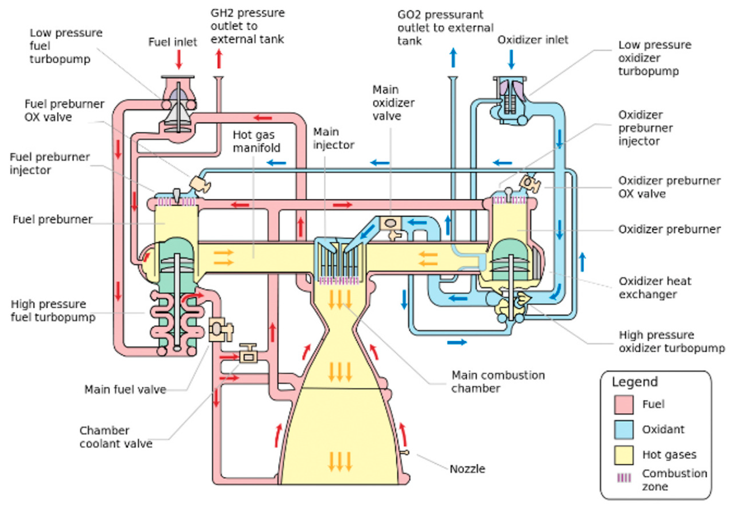
In the 1970s, the United States developed the Space Shuttle Main Engine (SSME), which employed a pump-fed propellant supply system and a hydrogen–oxygen staged combustion scheme, as shown in Figure 2 [23,24].
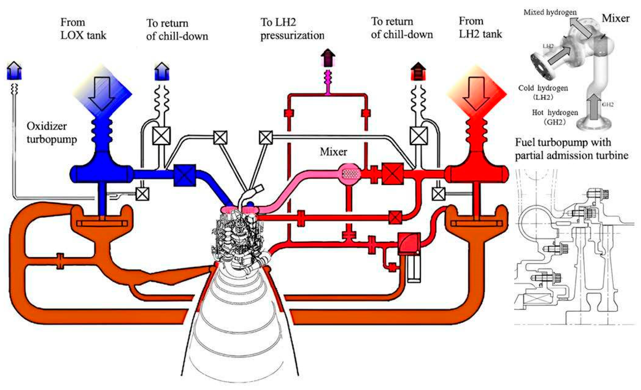
Its thrust could be modulated within a range of 50% to 109%, achieved by adjusting the valve openings in the oxidizer and fuel lines to regulate both thrust and mixture ratio [26,27]. During the same period, the Soviet Union developed the RD-170 liquid oxygen/kerosene engine and the RD-0120 hydrogen–oxygen engine, both of which regulated thrust and mixture ratio by adjusting the fuel flow to the preburner and combustion chamber through flow regulators [28,29,30]. In 1981, TRW developed the “FLYRT” variable-thrust engine for the “Sentinel” program. This engine used an adjustable cavitating Venturi tube for flow regulation and a high-pressure flow positioning pintle injector for dual regulation, achieving a thrust regulation ratio of 19:1 [31]. Starting in the 1990s, Pratt & Whitney in the United States, based on the RL-10 engine, achieved thrust regulation by installing bypass valves in the engine piping to regulate flow and completed cryogenic wide-range thrust regulation tests [32,33]. Building on this, the Voronezh Design Bureau in Russia collaborated with Pratt & Whitney to develop the RD-0146 hydrogen–oxygen engine, which has the capability to modulate thrust within a range of 50% to 100% [34]. As shown in Figure 3, the LE-5B-2 engine, developed by Mitsubishi Heavy Industries (MHI) as a liquid hydrogen/liquid oxygen engine, has demonstrated significant progress in its throttling capability. The engine is not only capable of thrust modulation from 60% to 100%, but also operates stably in idle mode at as low as 3%, relying solely on tank-head pressure without activating the turbine [35]. Since 2006, the “Merlin” series of engines has been used on the Falcon rockets. SpaceX has continuously improved these engines. In 2015, the Falcon 9 rocket successfully completed the world’s first recovery of a first-stage booster. The “Merlin-1D” engine used in this rocket employed a gas generator cycle and used a pintle injector similar to that of the LMDE for thrust regulation, with a thrust regulation range of 75% to 100% [35,36,37]. The Morpheus engine has successfully achieved deep throttling with liquid oxygen/liquid methane (LOX/LCH4), validated a 4:1 throttling capability and autonomous landing technology, and confirmed the feasibility of LOX/LCH4 propellants for in situ resource utilization (ISRU) [38,39].
During this stage, the thrust regulation range of variable-thrust LREs was significantly widened, and the flexibility of thrust regulation was enhanced. The application of variable-thrust technology expanded from single missions to a diverse range of scenarios, including deep-space exploration, orbit maintenance, and attitude control of space stations. Meanwhile, the reliability, response speed, and environmental adaptability of variable-thrust LREs were greatly improved.

2.3. Stage 3: The Reusability and Deep Regulation Stage Dominated by Commercial Spaceflight

Entering the 21st century, with the rise of commercial spaceflight and the extreme complexity of space missions such as rocket recovery and deep-space exploration (e.g., Starship reusability, Mars lander obstacle avoidance), variable-thrust technology faces stringent demands for deep thrust regulation, millisecond-level response, and high-frequency reusability. Building on the optimized cycle designs of liquid rocket engines from the second stage and the technical accumulation of electric servo mechanisms, the technological roadmap of variable-thrust LREs has shifted towards fully electric control systems, engine miniaturization, high integration, and intelligent algorithm-based control. On one hand, the design and application of full-flow staged combustion and electric pump cycles bring the performance of variable-thrust LREs closer to theoretical limits. Breakthroughs in technologies such as 3D printing further enhance the flow regulation precision of pintle injectors and flow regulators. Relying on high-precision sensors and intelligent control algorithms, real-time closed-loop control of propellant flow and combustion chamber pressure has been achieved. On the other hand, the miniaturization of electric servo mechanisms has matured. To reduce the structural weight of the engine itself and increase the rocket’s thrust-to-weight ratio, engine system design is moving towards high integration and lightweighting.
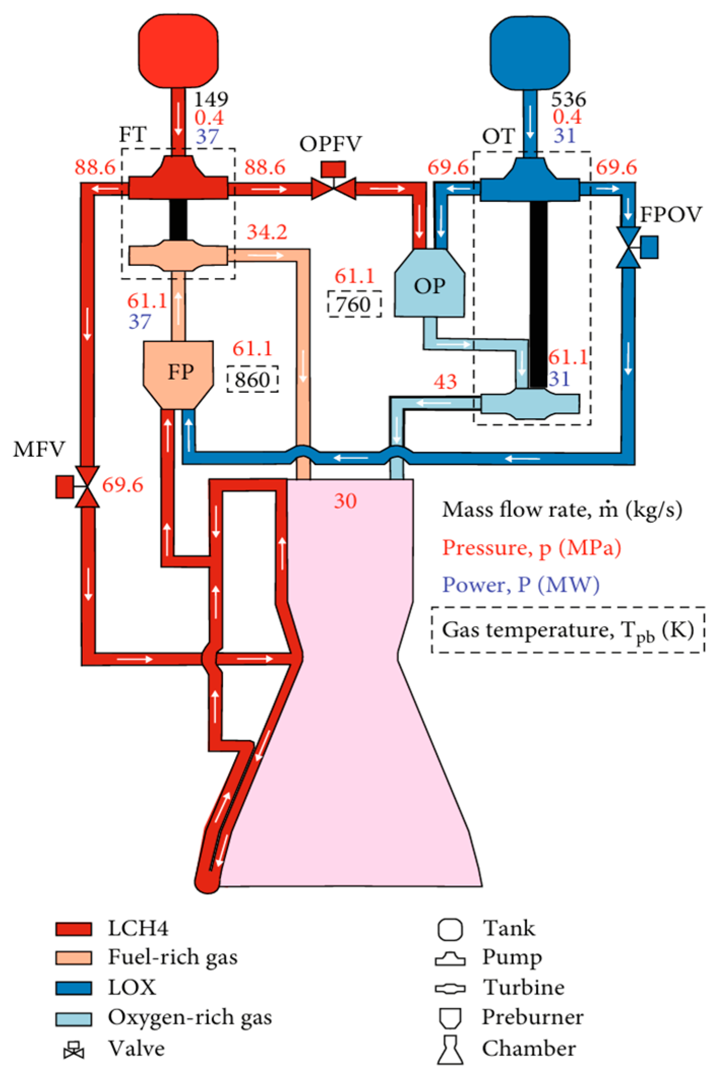
Due to the use of a gas generator cycle in the Merlin engine, despite continuous improvements and the subsequent development of several variants such as Merlin-1B, 1C, 1C Vacuum, 1D, and 1D Vacuum [40], it can no longer meet the demands of human exploration of extraterrestrial bodies. To achieve the goal of Mars colonization, SpaceX developed the Raptor engine, which was successfully tested in July 2019. It is the world’s first full-flow liquid oxygen/methane rocket engine, with a thrust range of 25% to 100% to meet the requirements of different flight phases, as shown in Figure 4 [41]. The Raptor 2 engine, an improved version of the first generation, offers enhanced thrust and reliability and achieves more precise thrust control. The Raptor 3 engine further simplifies the design by internalizing secondary flow paths and adding regenerative cooling to exposed components, reducing the need for external parts. From Raptor 1 to Raptor 3, there has been a significant improvement in thrust, specific impulse, and reliability, while the design has become more streamlined, lighter in weight, and superior in performance.
Another prominent commercial space company, Blue Origin in the United States, successfully launched the New Shepard suborbital vehicle propelled by the BE series engines on 20 July 2021, reaching an altitude of 100 km. Blue Origin’s BE-3 engine, which uses a hydrogen/oxygen expander cycle, can modulate thrust between 90 and 500 kN, with a thrust regulation range of 18% to 100% of the rated thrust. The BE-4 engine, featuring an oxygen-rich staged combustion cycle design, has a ground thrust of 2450 kN and has successfully completed variable thrust tests from 50% to 100% of its rated thrust. It will be used for the New Glenn launch vehicle. In December 2013, the Chang’e-3 probe, part of China’s Chang’e Phase II mission, successfully completed a soft landing on the Moon, marking China’s first soft landing on an extraterrestrial body. Its main engine, the YF-36, employs a pressure-fed flow positioning dual-regulation open-loop control scheme. Flow regulation is achieved using a variable-area cavitating Venturi tube, and a flow positioning pintle injector ensures relatively constant injection pressure drop during flow changes, enabling thrust regulation from 1500 N to 7500 N, with a maximum thrust of 8250 N [43,44]. The YF-36 engine has since been applied to deep-space exploration missions such as CE-4, CE-5, CE-6, and Tianwen-1 [45,46,47,48,49]. Domestic commercial space companies in China, targeting cryogenic propellants, wide-range thrust regulation, and reusability, have achieved numerous engineering applications in the field of high-performance liquid rocket engines. In 2019, LinkSpace successfully conducted China’s first recoverable rocket flight test with its NL-1 engine. Subsequently, LandSpace’s TQ-12 engine, the first domestic 80-ton liquid oxygen/methane engine, completed a successful test firing. In 2023, iSpace’s Hyperbola-2 completed China’s first full-scale first-stage vertical takeoff and landing (VTOL) and recovery flight test for a liquid rocket, with its JD-1 engine featuring deep thrust regulation capability [50].
During this stage, the technological development of variable-thrust LRE has shifted from being state-dominated to being led by commercial space companies, focusing on the engineering application of deep thrust regulation technology and reusable rockets, thereby transforming the traditional spaceflight model.
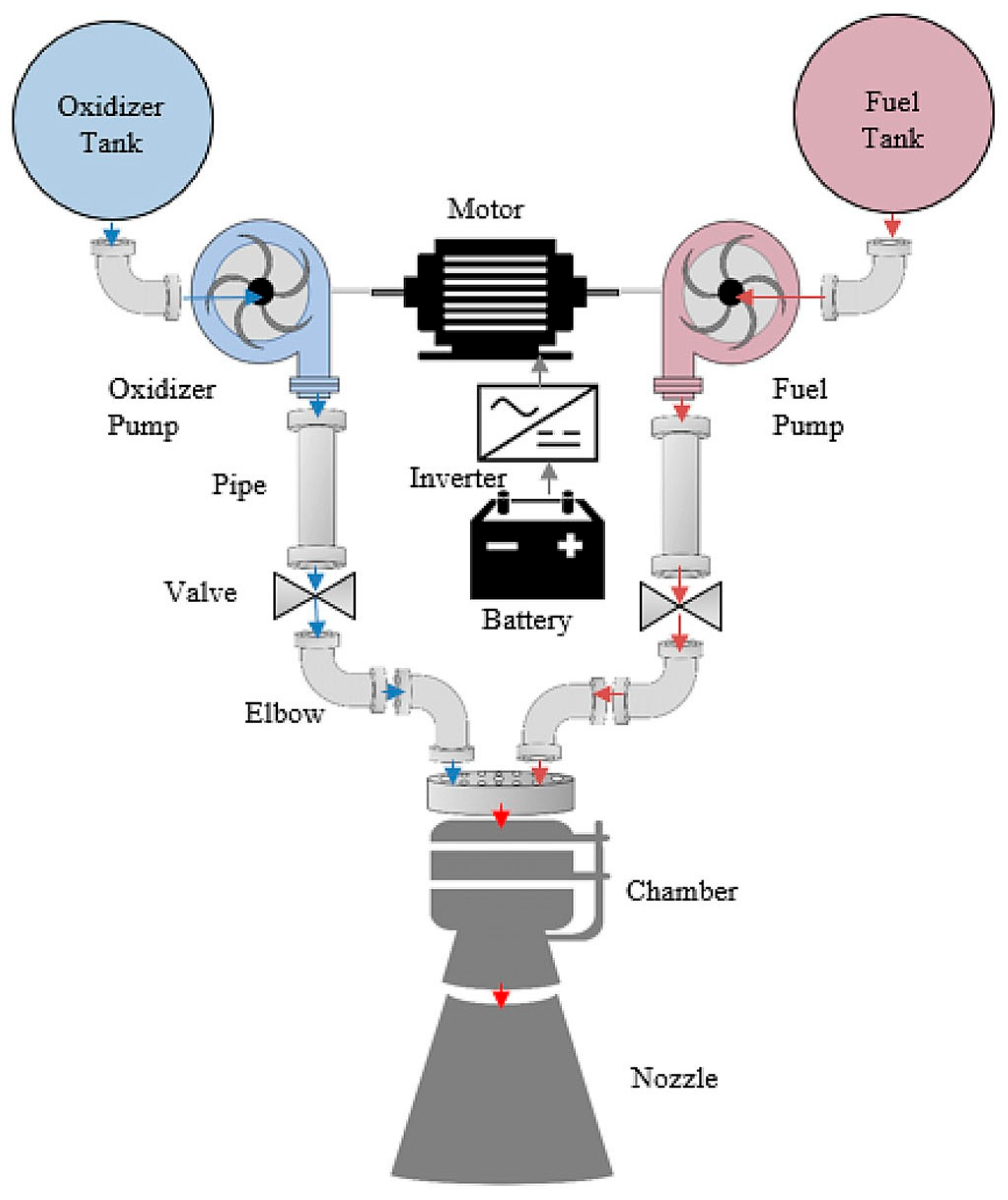
Overall, variable thrust liquid rocket engines have evolved from the type of traditional functional implementation to mission-oriented, low-cost, and adaptable types. In the future, three major areas may be concentrated on, namely, the system design of full-flow staged combustion liquid oxygen/methane engines, the reliability verification of electric pump cycles, as shown in Figure 5, and the technology for high-frequency reuse of engines, to provide market-driven innovative solutions for complex deep-space exploration missions.

3. Thrust Regulation Technology of Variable-Thrust LRE

There are two approaches to implementing thrust regulation: one is by adjusting the magnitude of thrust, and the other is by controlling the duration of thrust. Consequently, they are respectively termed variable-thrust engines and pulsed engines. The variable-thrust liquid engines discussed in this paper refer to liquid rocket engines that can modulate the magnitude of thrust over a wide range.
The thrust of a liquid rocket engine can be represented by the following equation:
F   =   m ˙   · v e + A e · P e   -   P a
where
F denotes the thrust;
m ˙ represents the mass flow rate of the propellant;
v e is the exhaust velocity;
A e is the exit area of the nozzle;
P e is the pressure at the nozzle exit;
P a is the ambient pressure.
The first term of the equation represents the momentum thrust, which accounts for over 90% of the total thrust when the propellant is determined. Therefore, the key to thrust regulation in variable-thrust LRE lies in the regulation of the exhaust gas mass flow rate. In addition to the rapid regulation of the exhaust gas mass flow rate, variable-thrust engines must also be capable of quickly adapting to a wide range of operating conditions. This is a highly complex process that involves flow regulation, propellant atomization, and combustion.
The core mechanism of thrust regulation technology lies in adjusting key parameters like propellant flow rate, combustion chamber pressure, or nozzle exit area to dynamically control the engine’s thrust. While the physical principles of these mechanisms provide the theoretical foundation for variable-thrust technology, translating this theory into practical engineering solutions remains a complex and critical challenge. Thrust regulation schemes for variable-thrust liquid rocket engines can be categorized into single-regulation schemes and double-regulation schemes based on the adjustment type. In the single-regulation scheme, thrust regulation is achieved solely by adjusting the propellant flow rate. Conversely, the double-regulation scheme simultaneously regulates both the propellant flow rate and the injection pressure drop. Several typical variable-thrust liquid rocket engines and their thrust regulation schemes are listed in Table 1. The design of propellant flow rate regulators and the dynamic matching of injector flow rate and pressure drop significantly impact the performance and applicability of variable-thrust systems. At its essence, variable thrust is achieved by adjusting the flow rate and mixture ratio of propellants entering the combustion chamber. This requires a well-designed propellant flow rate regulation system and must operate within the performance boundaries dictated by the engine cycle to ensure precise thrust regulation.
Thus, the following sections of this paper will delve into the core technologies and implementation methods of thrust regulation for liquid rocket engines. It will analyze their technical characteristics, advantages, disadvantages, and performance across different application scenarios, aiming to deliver a comprehensive reference for research in this field.

3.1. Propellant Flow Regulator

The flow regulator is a critical component in the propellant supply system. It adjusts propellant flow to enable variable thrust by changing the flow cross-sectional area or passage characteristics, allowing for precise flow control. Common flow regulators include throttle valves and adjustable cavitating Venturi tubes. The pintle injector, which can also regulate injection pressure drops, is another type of flow regulator and will be discussed in detail later regarding its pressure drop modulation.

3.1.1. Throttle Valves

Throttle valves regulate the propellant flow rate by adjusting their opening, which changes the cross-sectional area available for fluid passage. They can be pneumatic, electric, or hydraulic, depending on the actuation method. Throttle valves offer a wide regulation range, rapid response, and strong adaptability to different working fluids. However, they also feature a complex structure. Pneumatic valves are less precise, while electric and hydraulic valves need extra drive equipment and have higher maintenance costs.
As a core component for variable-thrust regulation, a throttle valve’s high-frequency response, high-precision regulation, disturbance rejection, and adaptability to extreme environments directly impact the accuracy, response time, and stability of thrust regulation. Chen et al. note that under wide-range throttling conditions, dynamic characteristic variations in the throttle valve can induce significant fluctuations in system parameters, thereby compromising the robustness of control algorithms [52]. Yao et al. demonstrated that the structural parameters (e.g., needle valve geometry, flow area) and operational parameters of throttle valves significantly influence dynamic response and control precision. Through targeted optimization of system architecture and control parameters, they achieved large-range, rapid-response, high-precision thrust control [53]. Witrant et al. proposed a data-driven control approach utilizing real-time system identification and controller reconfiguration. This method adapts to valve dynamics and enhances control performance, particularly in tracking accuracy [54]. Feng et al. developed an adaptive second-order fixed-time sliding mode controller to improve the valve’s rapid dynamic response and disturbance rejection capabilities [55].
Collectively, these studies establish that the valve’s dynamic behavior—governed by its design parameters and operating conditions—is the primary determinant of thrust-control authority and combustion-chamber pressure fidelity. The resulting parameter fluctuations defy legacy controllers, necessitating targeted system redesign, real-time data-driven model updates, and adaptive nonlinear control. The demonstrated success of these complementary approaches underscores the pivotal role of innovative valve design and control strategy in overcoming the central challenges of variable-thrust liquid rocket engine flow-regulation systems.
Furthermore, with the expanding utilization of cryogenic propellants, the application scenarios of throttle valves have transcended the confines of room-temperature propellants. Nevertheless, existing research predominantly centers on the throttling functionality and control strategies of such valves, with relatively scant attention paid to their adaptability and performance optimization under extreme conditions. Unlike room-temperature propellants, cryogenic propellants are prone to flashing and phase transition phenomena [56], which impose challenges on the stable operation of engines. Cavitation in cryogenic propellants can induce not only minor flow fluctuations but also structural damage to engines in severe instances [57]. Thermodynamic effects constitute the primary driver of cavitation in cryogenic propellants; a comprehensive understanding of the mechanisms governing the initiation, evolution, and suppression of such cavitation will substantially prolong the service life of cryogenic throttling valves and markedly enhance the stability of engine systems.
Current research endeavors are primarily conducted via two approaches: experimental observation and numerical modeling. Experimentally, high-speed visualization techniques are employed to observe the morphological evolution of cavitation, yielding data on pressure pulsations, temperature distributions, and void fractions [57,58]. In terms of numerical modeling, owing to the complexity inherent in two-phase flow modeling, the primary models encompass (1) bubbly flow models; (2) homogeneous mixture models; and (3) multiphase models [59]. Despite advancements in experimental and numerical simulation studies, several limitations persist: constrained by experimental and measurement methodologies, the data acquired from experiments are singular and insufficient to support rigorous validation of model accuracy. Additionally, modeling research has focused on the cavitation phenomenon per se, with a lack of evaluation regarding its impact on dynamic flow characteristics. Thus, there is an urgent need for quantitative research on the flow regulation characteristics and dynamic response behaviors of cryogenic propellant supply systems.

3.1.2. Adjustable Cavitating Venturi Tubes

In propellant supply systems, adjustable Venturi tubes are also widely used and offer unique advantages in specific conditions. They work by leveraging the Venturi effect—as fluid passes through a constricted section (throat), its velocity increases while pressure decreases. By adjusting the position of a cone within the throat to change its cross-sectional area, the flow rate can be controlled. The working principle is shown in Figure 6. This design is less mechanically complicated than throttle valves, as it has fewer moving parts, which reduces the risk of component failure. Moreover, in handling high-pressure propellant flows, the unique cavitation and flow characteristics of adjustable cavitating Venturi tubes result in relatively minor energy losses. This enables more efficient and stable propellant supply, especially in high-pressure environments.
According to the flow rate equation of Venturi tube,
Q = C d A 2 ρ 0 p 1 p s
Once the propellant’s vapor pressure is determined, the required throat area can be calculated. This allows for determining the regulating cone displacement needed to achieve precise flow control.
Using an adjustable cavitating Venturi for flow regulation can isolate pressure fluctuations between upstream and downstream. When the propellant pressure at the Venturi’s throat drops to its saturation vapor pressure, flow through the Venturi becomes independent of downstream pressure changes. This effectively blocks the impact of downstream fluctuations on upstream conditions, stabilizing flow regulation. A specially designed conical regulating surface enables linear flow adjustment over a certain displacement range, reducing nonlinear errors and enhancing control precision. By combining a servomotor with a ball screw, the regulating cone displacement can be precisely controlled, further improving the flow control accuracy of the adjustable cavitating Venturi.
Although effectively isolating pressure fluctuations between upstream and downstream, the Venturi tube’s throat and the regulating cone’s surface are subject to erosion and corrosion from cavitation, reducing their service life. The linear regulating cone requires high-precision machining and contains numerous internal precision components, which significantly increase manufacturing and maintenance costs. Moreover, the installation of adjustable cavitating Venturi tubes demands high accuracy. They are typically located in the piping before the combustion chamber, where the working environment is harsh, which can affect equipment performance.
The key advantage of an adjustable cavitating Venturi tube lies in its ability to precisely control the throat flow area via the displacement of a regulating cone, enabling linear flow regulation. This feature makes it excel in scenarios demanding high-precision flow control. Research on adjustable cavitating Venturi tubes focuses on two main aspects: one is to achieve precise flow control by altering the position of the regulating cone and to optimize the linear relationship between flow and cone position; the other is to address the control precision of the regulating mechanism, as well as the response speed and stability of the control system. This requires the optimization of the regulating mechanism’s design and innovation in experimental and numerical simulation technologies for the Venturi tube.
In the area of mechanism-design optimization for variable-geometry cavitating Venturis, Sekrecki presented a sizing methodology for variable-area cavitating Venturis in deeply throttled, variable-thrust liquid-propellant rocket engines, emphasizing the need to maintain continuous choking across the full flow range [61]. Liu et al. experimentally revealed that large diffuser angles generate pronounced flow-pressure oscillations and clear flow-rate fluctuations but yield faster response, whereas smaller angles afford greater stability at the expense of slower dynamics, allowing the trade-off between stability and responsiveness to be tuned via the expansion angle [62]. Shi combined experiments with CFD to examine Venturis having convergence angles of 19° and 45°, finding that the 45° angle more readily triggers stronger cavitation but incurs a higher pressure-loss coefficient. From these data, he derived a semi-empirical correlation linking cavitation number, pressure-loss coefficient, Reynolds number, and vapor-volume fraction, enabling performance estimation and design of Venturis across a wide range of geometries and scales [63]. Hwang et al. performed numerical simulations of cavitating flow in Venturis of various geometries and noted that the single-stage diffuser angle exerts only limited influence on flow-control authority. In cavitating-choked flow, mechanical energy is primarily consumed to enlarge the cavitation zone rather than to accelerate the bulk flow; the diffuser angle mainly affects local pressure-wave propagation and energy recovery, contributing little to overall flow regulation [64].
In terms of dynamic characteristics, Tan et al. developed a feedback flow-control scheme based on a variable-area cavitating Venturi. By real-time adjustment of the pintle position to counteract pressure disturbances, the strategy limits the steady-state flow-rate error to within 1.2%, enabling precise oxidizer-flow control and thus enhancing hybrid-rocket performance. Experimental verification under three target thrust levels (400 N→600 N→400 N) showed average thrust deviations below 0.5% and transition times reduced to approximately 1.0 s. The linear response characteristic inherent to the variable Venturi is exploited effectively, providing a viable path toward closed-loop thrust and flow control [65,66]. Tian et al. validated the dynamic-flow-modulation capability of a designed variable-area cavitating Venturi through four sets of water-flow tests, demonstrating that the discharge coefficient depends solely on the pintle stroke under constant upstream pressure [67]. Apte et al. introduced an adaptive-mesh-refinement approach for CFD simulations, elucidating how velocity gradients and fluid-element expansion/contraction govern vortex development. This method matches the accuracy of conventional grids while markedly improving computational efficiency, offering a practical route for high-fidelity simulation of cavitation–turbulence interactions [68].
Collectively, the above studies have advanced the geometric design, dynamic response, control strategies, and performance optimization of variable-area cavitating Venturis. Nevertheless, their transition to engineering practice still confronts two intertwined bottlenecks:
  • Under the rapid mode-switching demanded by deep-throttling variable-thrust engines, the coupled mechanism between cavitation and turbulent fluctuations remains poorly quantified, leaving the dynamic response to thrust step changes without a rigorous mathematical description. This gap severely limits the robustness of high-precision control-law design.
  • Existing achievements are almost exclusively based on room-temperature propellants; systematic investigations for cryogenic propellants such as LOX/methane are conspicuously absent. Foundational questions—ranging from how cryogenic cavitation dynamics influence flow-modulation characteristics to the establishment of discharge-coefficient calibration, dynamic-response characterization, and model construction under cryogenic conditions—remain open. Consequently, three critical voids must be filled: (i) a transient cryogenic cavitation–turbulence coupling model for variable Venturis, (ii) a dynamic calibration methodology for discharge coefficients under variable operating conditions, and (iii) a cryogenic-adaptive control architecture.
In variable-thrust LRE, both throttle valves and adjustable cavitating Venturi tubes serve as key flow regulation devices, each offering distinct advantages and developmental potential. Adjustable cavitating Venturi tubes excel in achieving linear flow control by modulating the throat area and demonstrate superior reliability in high-pressure, high-flow, and extreme conditions, such as liquid oxygen/kerosene propellant systems. This makes them especially suitable for variable-thrust engines requiring high-precision dynamic flow regulation. Throttle valves, with their compact design and rapid response, are better suited for low-pressure or low-to-medium-flow systems and are commonly used for fine flow adjustments or as a redundant control mechanism. As the demand for spacecraft for intelligent and reusable propulsion systems grows, the technological boundaries between these two devices will progressively merge. Future adjustable cavitating Venturi tubes can integrate intelligent actuators for precise closed-loop control. Throttle valves must advance in materials and sealing technologies to adapt to cryogenic and ultra-high-pressure environments. Digital twin technology, leveraging multi-physics coupling, will drive their collaborative optimization. In next-generation space propulsion systems, such as deep-space exploration and reusable launch vehicles, they will form complementary advantages, jointly meeting high-reliability and broad-operating-range propulsion needs. In addition to mechanical throttling for flow regulation, electric pumps in pumped-cycle systems also play a role in flow control. They offer rapid response and high regulation precision, making them suitable for large-thrust variable-thrust LREs.

3.2. Injector Dynamic Pressure Drop Matching Technology

3.2.1. Combustion Organization Challenges of Traditional Injectors at Low Operating Conditions

The injector is a core component of a liquid rocket engine that determines the propellant injection characteristics and combustion efficiency, directly impacting the engine’s thrust and performance. During variable-thrust operations, the upstream flow regulator adjusts the propellant mass flow rate, and maintaining a sufficient pressure drop across the injector is essential for proper propellant atomization and stable combustion. The main types of injectors currently in use are coaxial, centrifugal, and impinging jet injectors.
Coaxial injectors deliver propellants through concentric annular gaps, using gas–liquid shear forces for atomization, ensuring high combustion efficiency [69]. They enable thrust regulation by deactivating some injection units. However, at low flow rates, the atomization performance is poor due to reduced shear forces. Typical applications of coaxial injectors include the Russian RD-180 engine and Europe’s Vulcan engine [70]. Centrifugal injectors use swirling flows to generate centrifugal force, forming liquid films that break up into droplets. They are compact in design and well-suited for space-constrained engines. At low flow rates, they experience reduced swirl intensity and atomization quality. Additionally, they are prone to coking and blockage at high temperatures [71]. Impinging jet injectors utilize multiple straight orifices for propellant injection, enhancing mixing through jet impingement. With a simple, fixed design, they achieve good atomization via optimized orifice layout [72]. However, at low flow rates, the momentum of the propellant jets is insufficient to guarantee atomization effectiveness.
Traditional injectors often struggle with poor atomization, mixture ratio shift, and combustion oscillation during deep thrust regulation, especially at low operating conditions. These issues significantly degrade the engine’s variable-thrust performance and place demanding requirements on the propellant supply system. To achieve deep thrust regulation, extra flow regulation devices are typically needed in the propellant supply system. Moreover, ensuring combustion stability during deep throttling is essential.

3.2.2. Dynamic Pressure Drop Matching of Adjustable Pintle Injectors

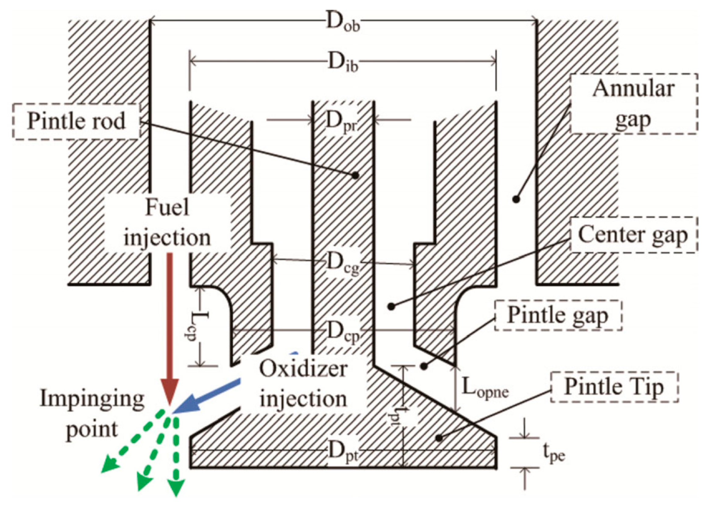
The pintle injector, known for its simple structure and high combustion efficiency, is widely used in variable-thrust LREs with different cycles [31]. Despite over 60 years of development and wide application, most research on it remains unpublicized. This is mainly because the related technology is often regarded as a highly sensitive core technology in aerospace, with both military and civilian applications, and thus is strictly classified. As shown in Figure 7, the pintle injector’s design features a pintle that extends into the combustion chamber. One propellant flows through the central channel of the pintle and is injected radially through orifices near the pintle head. The other propellant is injected axially through an annular gap outside the pintle. The radial jets intersect with the annular liquid film, achieving efficient atomization and mixing of the propellants.
The pintle sleeve of an adjustable pintle injector can move. This gives it the ability to dynamically match flow rate and injection pressure drop. During deep thrust regulation, as the upstream flow-regulating device changes the propellant flow, the pintle sleeve moves. This adjusts the injection area and keeps the injection pressure drop at the right level. This dynamic matching ensures stable combustion in the combustion chamber. Thanks to this ability, adjustable pintle injectors have a clear edge in variable-thrust LREs.
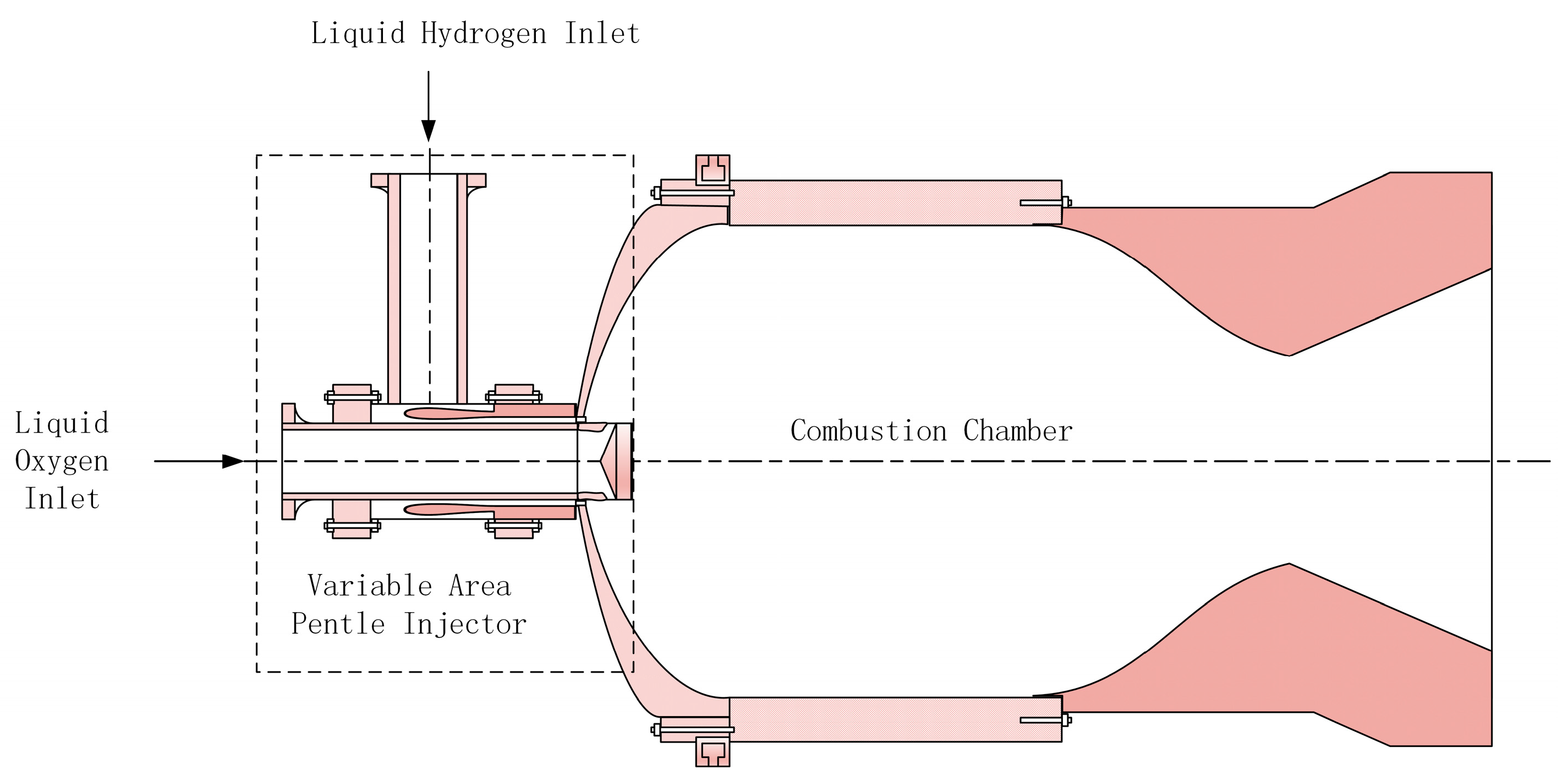
TRW has played a significant role in the development of pintle-injector engines and has developed over 60 different varieties of liquid-rocket engines with pintle injectors. Its 40 Klbf LOX pintle engine, as shown in Figure 8, by adjusting the geometry of the pintle injector (e.g., oxidizer-slot size and number, fuel-gap width) as well as the fuel-film-cooling flow rate, has achieved stable operation and high-efficiency combustion across different thrust levels [74]. The TR202 LOX/LH2 deep-throttling engine uses a variable-area pintle injector. It changes the LOX injection area during throttling, keeps the pressure drop constant, and ensures high performance and stability across a 10:1 throttling range [75].
Although adjusting the injection orifice area maintains a stable pressure drop, it simultaneously disrupts the momentum-flux balance between gas and liquid, causing spray-angle deviation and Sauter Mean Diameter (SMD) degradation [76,77]. These effects impair atomization quality, mixing homogeneity, and combustion stability. Consequently, profile-orifice co-design is required to optimize both momentum ratio and spray cone angle under transient conditions, and a clear dynamic pressure-drop–flow-rate matching mechanism must be established to underpin a standardized design methodology for variable-pintle injectors. Researchers have conducted extensive theoretical, experimental, and numerical work on these two fronts.
In terms of the influence of structural design on atomization performance for variable-pintle injectors, Heo et al. proposed a spray-angle prediction model that incorporates radial-flow deflection and axial-velocity decay, enabling accurate estimation of the spray angle as a function of throttling level and thereby supplying a precise atomization-characterization tool for variable-pintle injectors [78]. Nardi et al. examined how different design constraints affect injector performance and found that combining axial continuous flow with radial-orifice flow yields superior mixing and flow-control capability, providing experimental evidence linking geometric design to atomization performance [79]. Rajendran highlighted the need to consider spray angle, Sauter Mean Diameter (SMD), TMR, and throttling conditions comprehensively when designing pintle injectors [80]. Mishra et al. showed that spray angle varies linearly with TMR and that increasing TMR degrades combustion efficiency; they also summarized correlations among spray morphology, droplet distribution, and combustion efficiency for various geometric parameters, offering a multi-parameter design guideline [81]. Cha et al. introduced a quadratic-programming-based optimization framework that quantitatively relates design variables (pintle tip diameter, tip angle, annular-gap thickness, pressure drop) to performance metrics (SMD, atomization cone angle, vaporization distance), clarifying the positive or negative influence of each parameter [82]. Li et al. revealed that the root geometry of the orifice creates a local high-pressure zone via gas–liquid impingement, sharply increasing the discharge coefficient’s sensitivity to local momentum ratio (LMR) and back-pressure. Additionally, the sleeve-exit profile governs air-film shear, inducing radial non-uniformity in the spray: edge SMD > 100 μm versus center SMD ≈ 50 μm, supplying critical insights for orifice-shape optimization and aerodynamic contouring of variable-pintle injectors [83].
Regarding investigations into the pressure-drop–flow-rate matching mechanism for variable-pintle injectors, Li et al., through cold-flow and hot-fire experiments, first presented a piecewise pressure-drop–stroke correlation for a pintle–swirl compound injector over a 6.8:1 flow-turndown range. They further identified that when the annular area falls below one-third of the total radial-orifice area, the system pressure drop is dominated by the annulus; otherwise, fixed orifices govern the drop, offering a rapid experimental calibration basis for variable-pintle injectors [84]. Radhakrishnan et al. conducted wide-range flow tests (59–559 g/s) and derived an explicit pressure-drop relation as a function of both flow rate and pintle stroke, thereby incorporating stroke directly into the pressure-drop–flow-rate model for the first time [85]. Ninish et al. found that reducing the annular gap elevates the Weber and Reynolds numbers, improving the pressure-drop–flow-rate behavior and shrinking droplet sizes from 840 μm and 650 μm to the 100 μm range, elucidating how geometric parameters modulate the pressure-drop–flow-rate matching mechanism [72].
Current investigations of pintle injectors have concentrated on structural design, the dynamic interplay between flow rate and pressure drop, and the resulting combustion efficiency and stability. Yet, the dynamic characteristics of flow and pressure drop are almost always examined under steady-state or simplified dynamic conditions; for instance, Heo’s spray-angle model and Nardi’s cold-flow experiments do not account for how rapid thrust transients alter atomization behavior, leaving the atomization response mechanism during dynamic transients essentially unknown. Although Rajendran stresses that spray angle, SMD, and TMR must be treated jointly, most studies still isolate single-parameter effects and remain short of a quantitative, multi-parameter coupling model. Likewise, the pressure-drop–flow-rate matching strategies proposed by Li (piecewise matching curves) and Radhakrishnan (explicit pressure-drop versus flow-rate and stroke correlations) are derived from steady-state data; they do not capture the transient features of thrust-step modulation. The lag in flow-rate response and its coupling with pressure-drop oscillations are consequently undefined, preventing these models from supporting the control requirements of highly dynamic engines. In real liquid-propellant rocket operation, upstream pressure disturbances continuously upset the pressure-drop–flow-rate balance, yet the literature generally assumes a stable pressure drop and neglects how such fluctuations affect spray angle and SMD, let alone devising dynamic compensation strategies. The present over-reliance on empirical correlations for variable-pintle injector design reflects a fundamental gap: the absence of a clear dynamic coupling mechanism linking pressure drop, momentum ratio, atomization quality, and combustion efficiency. This deficit threatens combustion-chamber stability and raises the risk of closed-loop regulation failure during high-frequency thrust regulation.

4. Variable-Thrust LRE System Control Technology

As previously stated, the thrust regulation range and stability of variable-thrust LREs are directly restricted by the performance boundaries of flow regulation devices and injector dynamic matching technology. To achieve precise control of spacecraft in extreme conditions, structural optimization of key components alone is insufficient to meet the required control accuracy and response speed. Therefore, advanced closed-loop control strategies for engine systems are crucial for overcoming flow regulation limitations and unlocking the engine’s performance potential.

4.1. Difficulties in System Control of Variable-Thrust LRE

The key to system control of variable-thrust LRE lies in achieving precise regulation of combustion chamber pressure and mixture ratio by adjusting valve openings within operational constraints. However, the actual control process is complicated by multivariable coupling, time lag, and disturbances, which collectively create significant difficulties for precise engine control. These difficulties are mainly reflected in:
  • Multivariable coupling
The system control of variable-thrust LRE involves synchronously adjusting multiple key parameters that are interrelated and influence one another, creating a complex multivariable coupling relationship [86]. Chamber pressure, a critical factor affecting thrust, is closely related to parameters such as propellant flow and injection pressure drop. Precise control of the propellant mixture ratio is also essential, as it directly impacts combustion efficiency and thrust output. Adjustments to the injection pressure drop can, in turn, affect propellant atomization and combustion stability. This multivariable coupling significantly increases the complexity of system control. For example, when the injection area is altered to change the propellant flow, the chamber pressure changes accordingly, which then affects the propellant mixture ratio and combustion efficiency. To address this complexity, it is necessary to construct a multi-input multi-output control framework based on a state-space model that accounts for the interactions between variables, thereby achieving precise control of the entire system.
2.
Control signal and response delays
The propellant feed lines, a vital part of the propulsion system, can cause hydraulic delays that pose challenges for closed-loop control. During actual propellant transfer, the propellant must flow through a certain length of piping to reach the combustion chamber. This creates a transport lag between control signals and system response, making it difficult for the control system to adjust thrust in a timely and accurate manner. This lag can degrade control accuracy and potentially destabilize the system. The delay between control signals and responses constitutes one of the critical challenges in achieving high-precision thrust control. It is necessary to optimize the system structure and control parameters to realize fast response and high-precision thrust control [53].
3.
Harsh operating environment with strong disturbances
In actual operation, thrust regulation systems are subject to various internal and external disturbances, such as airflow perturbations, structural vibrations, propellant supply fluctuations, and combustion instability [87]. These disturbances can disrupt control signals, cause thrust fluctuations, and affect system stability and mission execution accuracy. Therefore, it is necessary to strengthen the system’s anti-disturbance design to enhance its ability to withstand and suppress disturbances. This ensures stable and precise thrust control in complex environments. Common anti-disturbance methods include adopting robust control strategies, adding filtering links, and optimizing sensor placement.
4.
Strong nonlinear characteristics
The dynamic characteristics of variable-thrust liquid rocket engines exhibit strong nonlinear characteristics, especially during wide-range thrust regulation [88]. For instance, combustion efficiency changes with the demand for thrust adjustment [89]; particularly under low-thrust conditions, combustion efficiency decreases significantly, and this change is nonlinear, requiring precise control strategies to optimize combustion efficiency. In addition, the nonlinearity of flow regulation, thermodynamic nonlinearity, and the nonlinear motion of actuators such as valves all contribute to stronger nonlinear characteristics of the system.
These characteristics render the engine system model more complex. Traditional linear models cannot accurately describe the system’s dynamic characteristics, creating an urgent need for more complex nonlinear models. However, nonlinear modeling relies on a large amount of experimental data and more sophisticated mathematical models, while the prediction accuracy of the established models is limited. Meanwhile, ensuring system stability also poses challenges to the system control of variable-thrust liquid rocket engines.

4.2. Control Strategies for Variable-Thrust LRE

Many studies have focused on the aforementioned issue. From an engineering application standpoint, system control strategies can be classified as open-loop control (which executes predefined commands without real-time feedback) and closed-loop control (which dynamically adjusts control actions based on sensor measurements). Closed-loop control strategies can be further divided into those using linear-model-based feedback control (relying on linearized models at operating points, e.g., PID/LQR controllers) and robust control (designed to maintain stability under system uncertainties and external disturbances, e.g., μ-synthesis).
  • Open-loop control
Open-loop control requires extensive testing to establish precise mathematical models. It directly drives flow-regulating mechanisms via command signals without relying on real-time feedback. This architecture offers simplicity, avoiding sensor failure issues in extreme environments and suiting scenarios with limited computational resources (e.g., shipboard systems). However, open-loop control heavily depends on experimentally derived mathematical models. Time-varying factors—such as propellant two-phase flow effects, combustion chamber carbon deposition, and turbopump performance degradation—cause preset models to progressively deviate from actual conditions, critically jeopardizing long-duration mission reliability. Consequently, open-loop control is typically applied in low-disturbance environments: initial thrust-transient phases, fuel pre-filling, and emergency shutdown sequences. Early deep-space rockets achieved thrust regulation via predefined valve timing without real-time correction. The RD-120 engine utilized open-loop control, obtaining characteristic parameters of regulating valves and turbopumps through extensive ground testing to manage thrust and mixture ratio [90]. Dai et al. developed an open-loop control algorithm that balances rocket performance and component lifespan, later applied to extend the Space Shuttle Main Engine’s service life [91]. Kiforenko et al. proposed an open-loop optimal thrust control strategy for liquid rocket engines. By establishing mathematical relationships between propellant mass flow rate and thrust, reducing control variable dimensionality, and solving thrust control curves under mixture ratio and chamber pressure constraints, they achieved pre-programmed thrust control [92].
Despite advantages in structural simplicity and extreme-environment tolerance, open-loop control’s high dependence on mathematical models incurs substantial engineering costs. Nonlinear factors—including propellant property drift, injector dynamic response lag, and high-frequency chamber pressure disturbances—render test-calibrated open-loop models inadequate for full operational control. Closed-loop architectures with dynamic feedback provide a new technical pathway for precise thrust regulation.
2.
Feedback control based on linear models
The integration of sensors for temperature and pressure fluctuation measurements with open-loop control establishes a closed-loop architecture, substantially improving control performance and robustness. The LE-5B engine implemented closed-loop control for thrust and mixture ratio regulation [93]. JAXA’s LE-X adopted a multivariable decoupling strategy using three electric ball valves to independently govern thrust, mixture ratio, and turbine inlet temperature, achieving 21–109% throttling capability during test-stand validation [94]. Liquid rocket engines possess inherently strong nonlinear dynamics. Direct nonlinear controller design necessitates complex mathematical methodologies and imposes demanding computational requirements. Owing to modeling and identification constraints, comprehensive nonlinear control remains primarily limited to simulations with minimal real-world applications. Linearized models—simplifying nonlinear systems into linear time-invariant forms near steady-state operating points—significantly reduce control complexity. Hu et al. developed a flow controller for electric-pump-fed rocket engines, noting that PID controllers effectively track ramp signals but generate severe output oscillations during transient phases [95]. Sopegno et al. evaluated LQR, LQG, and PID controllers for thrust vector control during the boost phase, demonstrating the PID controller’s superior disturbance rejection and steady-state error elimination against aerodynamic uncertainties and modeling errors [96].
While linear feedback methods offer structural simplicity and engineering practicality under steady-state conditions, they exhibit critical limitations: restricted bandwidth hindering strong nonlinear transient handling; integral windup during deep throttling causing response lag; and tuning difficulties in coupled multivariable systems, necessitating supplemental strategies such as decoupling, robust control, or adaptive control.
3.
Robust control
To ensure system stability and high performance under strong nonlinearity, parametric uncertainties, and external disturbances, robust control strategies have been applied to liquid rocket engine systems. The core principle involves quantifying system uncertainties and designing controllers that maintain stable operation under such uncertain conditions. Santana et al. implemented robust control theory on linearized liquid rocket engine models, demonstrating its capability to estimate required stability margins [97]. Kamath et al. designed a robust controller for precision rocket landing using multivariable feedback control and Youla parameterization, with performance validated through simulations [98]. Kurniawan et al. developed a μ-synthesis-based robust controller that effectively handles uncertainties and disturbances while maintaining stability across varying conditions [99]. Pérez-Roca et al. proposed a model-based robust control method for reusable liquid rocket engines, achieving precise trajectory tracking and constraint management from startup transients to throttling phases [100]. Key technical elements include uncertainty modeling, nonlinear compensation strategies, multivariable dynamic decoupling techniques, real-time disturbance observer design, and fault-tolerant control architectures—collectively enabling high-precision stable control of variable-thrust engines under complex perturbations like parameter variations and propellant coupling oscillations.
In recent years, artificial intelligence, particularly machine learning algorithms and digital twin technologies, has exerted significant influence on the design and operation of liquid rocket engines. Waxenegger-Wilfing et al. proposed a deep reinforcement learning-based approach to address the optimal control problem of liquid rocket engines during transient phases. The trained controller exhibits minimal computational workload for calculating control actions, making it suitable for closed-loop control in transient stages [101]. Bucci et al. developed a neural network-based controller for transient control of the LUMEN engine, demonstrating its performance in tracking reference trajectories and satisfying engine constraints [102]. Dresia et al. integrated machine learning with transient simulation environments to design a neural network-based controller, achieving dynamic adjustment of combustion chamber pressure between 40 and 80 bar through regulation of up to six flow control valves [103]. Jimenez Mena et al. conducted digital twin modeling and simulation for the RL10-3-3A expander cycle engine, constructing a complete engine model from tanks to nozzle based on the Simcenter Amesim platform. Combined with flight dynamics models, they evaluated its startup performance under real flight conditions for the Delta IV GTO mission [104]. Ye et al. proposed a digital twin framework for structural health management of reusable spacecraft, which is divided into offline and online phases—each containing four modules—to enable effective management of structural health. This framework demonstrates high accuracy and reliability, particularly in predicting fatigue crack propagation [105].
Existing studies are mostly based on simplified dynamic models, thus having limited capabilities for complex nonlinear dynamic compensation. Although machine learning, digital twin, and other technologies have become effective tools for the design and control of liquid rocket engines, providing new approaches for accurate modeling of engines, their “black-box” characteristics mean that the improvement of their credibility depends on model optimization and verification. In addition, with the improvement of control accuracy and system complexity (such as high-order characteristics), these control strategies have higher requirements for hardware resources. Therefore, it is necessary to explore more efficient control strategies under the premise of balancing accuracy and computational efficiency.

4.3. Engineering Challenges in Advanced Control Strategy Implementation

Current control methodologies effectively address fundamental steady-state regulation but encounter unresolved difficulties: inadequate characterization of strongly nonlinear transient responses, constrained precision in multivariable coupling/decoupling, and deficient robustness against extreme disturbances. Persistent limitations span both theoretical and engineering domains, including sensor reliability bottlenecks, control-structure coupled vibrations, and adaptability challenges under extreme operating conditions. Furthermore, while intelligent controllers based on robust control strategies are predominantly applied to thrust vector control, their theoretical research and engineering implementation for complete engine system control remain underdeveloped.
  • Sensor reliability bottlenecks
In liquid rocket engine control systems, sensors are tasked with real-time measurement of critical parameters such as pressure, flow rate, and displacement, where measurement accuracy directly governs control effectiveness. However, the extreme operational environment frequently induces sensor failures, calibration drift, and noise interference, leading to measurement distortion and compromised control decisions. Overcoming these limitations necessitates deploying high-reliability precision sensors integrated with redundant configurations, fault-diagnosis algorithms, and fault-tolerant control architectures to enhance both system reliability and data quality.
2.
Nonlinear model-based controller design and application
Variable-thrust LRE systems exhibit inherently strong nonlinear characteristics, including dynamic variations in cryogenic propellant supply, combustion process instabilities, and hydrodynamic coupling effects. Conventional linearized models fail to accurately describe such strongly nonlinear systems, resulting in insufficient control precision or system instability. High-fidelity nonlinear mathematical models are urgently required to precisely characterize the dynamic behavior of variable-thrust systems. Implementing control strategies such as sliding mode control and model predictive control, along with data-model fusion techniques for real-time parameter correction, can improve controller adaptability to nonlinear dynamics. Nevertheless, the inherent conflict between model complexity and real-time computational feasibility persists, while model uncertainties further challenge system stability guarantees.
3.
Control-structure coupled vibrations
During thrust regulation, interactions between control actuators and engine structures may induce coupled vibrations such as Pogo oscillations [106]. These vibrations can precipitate structural fatigue, component damage, and degraded control precision, potentially compromising system safety. As demonstrated by Yang et al., thrust harmonic-induced mechanical vibrations propagate through feedback systems to affect motor thrust, establishing a closed-loop coupling mechanism. Their approach involving motor structural optimization, mechanical system refinement, and active compensation strategies significantly enhanced dynamic control precision [107]. Consequently, a comprehensive investigation of control-structure coupling mechanisms—through optimized control system design, vibration isolation measures, and anti-vibration control algorithms—is essential to suppress coupled vibrations and ensure stable system operation.

5. Conclusions and Prospects

5.1. Conclusions

Variable-thrust liquid rocket engines, serving as the core power units for deep-space exploration, reusable launch vehicles, and precision propulsion systems of spacecraft, have undergone a transformative evolution from early mechanical regulation to full-electronic intelligent control. The technological development trajectory of variable-thrust liquid rocket engines is systematically combed in this paper, and a comprehensive review of research advancements is presented from the perspectives of thrust regulation techniques and system control strategies. However, due to the high nonlinearity of the system, closed-loop control is predominantly applied to steady-state conditions, whereas open-loop control remains the primary approach for transient control. Reinforcement learning and digital twin technologies demonstrate significant application potential in system modeling and control for variable-thrust liquid rocket engines. However, the “black-box” characteristics of these technologies render their credibility contingent upon extensive real-data validation, thereby limiting widespread engineering adoption. Continuous wide-range thrust adjustment is achieved in current studies through dual-regulation schemes that dynamically match propellant flow control devices with injection pressure drops. A typical example is the coordinated application of adjustable cavitating Venturis and pintle injectors. Pintle injectors have been established as critical components for deep throttling owing to their inherent flow-pressure adaptability, but their dynamic characteristic modeling and atomization mechanisms still require further in-depth research. In the field of system control technologies, the evolution of control methods has advanced from traditional open-loop control to closed-loop robust control, with strategies gradually being driven toward intelligent solutions. Additionally, significant breakthroughs have been made in cycle architectures and structural designs. The thrust regulation boundaries have been remarkably expanded and efficiency improved through the application of novel cycle modes, including full-flow staged combustion cycles, electric-pump cycles, and electric expander cycles. System performance and dynamic response capabilities are further enhanced by the lightweight integrated design of flow control devices and pintle injectors. Robust support is provided by these technological advancements for current mission requirements of space drones, such as crewed lunar missions, Mars exploration, and suborbital vehicle recovery operations, demonstrating their critical role in advancing space exploration and reusable launch technologies.

5.2. Prospects

Although thrust regulation and control technologies have progressed, demands driven by commercial spaceflight—specifically reusable low-cost systems and precision control for complex deep-space missions—necessitate innovation and breakthroughs in thrust regulation and control techniques. Converging with AI development trends, more effective modulation strategies must be explored. Focusing on these challenges, this paper proposes the following research prospects and future work:
  • Application prospects and challenges of cryogenic propellants: Cryogenic propellants, with their high specific impulse, clean combustion characteristics, and potential as core fuels for in situ resource utilization on Mars, have become a key option for high-frequency reusable commercial space missions and deep-space exploration tasks. However, their application in variable-thrust engines faces severe challenges: the effectiveness and robustness of existing design criteria and control systems based on room-temperature propellants under cryogenic and wide-range variable operating conditions need urgent verification, and the problem of unsteady flow fields caused by cavitation and flashing has not been fundamentally solved. Future efforts should focus on breaking through cryogenic wide-range flow regulation technologies, reducing the model’s dependence on empirical parameters based on the phase change characteristics of propellants, and developing new types of cryogenic throttling devices and rapid-response control systems.
  • Combustion stability during deep throttling: Deep thrust regulation relies on the wide-range flow adjustment capability of propellant regulating devices. However, issues such as nonlinear fluctuations in combustion chamber pressure, decreased combustion efficiency, and deteriorated atomization and mixing caused by extreme throttling conditions urgently require breakthroughs through dynamic coupling design. The core to solving these problems lies in establishing a real-time matching mechanism among injection pressure drop, flow rate, and pintle stroke. Through the collaborative design of profiles and injection orifices, the imbalance of gas–liquid momentum ratio caused by injection area adjustment can be eliminated, ensuring the stability of spray cone angle and Sauter Mean Diameter (SMD) under wide operating conditions. Meanwhile, transient CFD simulations should be used to reconstruct the processes of liquid film shear and gas–liquid collision, quantifying the dynamic laws of spray cone angle deviation and SMD deterioration during thrust steps. Reinforcement learning algorithms can be employed to dynamically regulate the pintle stroke and annular gap area, achieving stable combustion control under pressure drop fluctuations. Ultimately, it is necessary to verify through ground and flight tests covering all operating conditions and construct a highly robust injector design system integrating dynamic pressure drop compensation, multi-parameter coupling optimization, and transient atomization control so as to fundamentally solve the combustion instability under deep throttling.
  • Integration of high-fidelity variable-thrust engine system modeling with advanced control strategies: The strong nonlinear characteristics of variable-thrust liquid rocket engine systems make accurate modeling challenging. Issues of data noise and model mismatch are particularly prominent in extreme environments, which not only affect control performance and reliability but also exacerbate the contradiction between computational resource requirements and real-time correction. Future research should integrate high-fidelity system models with advanced control strategies, improve parameter identification accuracy through experimental calibration and data-driven modeling, and develop adaptive control algorithms under environmental uncertainties. The development of intelligent engine control technologies based on artificial intelligence and digital twin technologies will provide more effective solutions to the aforementioned problems of data noise and model mismatch. Meanwhile, it is necessary to balance computational efficiency and model fidelity using methods such as model order reduction, thereby forming an intelligent control system oriented toward engineering applications.

Author Contributions

Conceptualization, M.S. and B.X.; methodology, M.S. and B.X.; validation, H.D., B.X. and X.W.; formal analysis, M.S.; investigation, M.S. and X.L.; resources, X.W., S.L. and W.Z.; data curation, M.S. and X.L.; writing—original draft preparation, M.S.; writing—review and editing, M.S., X.L. and B.X.; visualization, M.S.; supervision, W.Z. and W.Y.; project administration, X.W.; funding acquisition, X.W. All authors have read and agreed to the published version of the manuscript.

Funding

This work was partially supported by the National Natural Science Foundation of China (Grant No. 12302382) and the Research Project of Science & Technology (Grant No. 202401-RCGC-ZZ-004).

Conflicts of Interest

The authors declare no conflicts of interest.

References

  1. Roma, A. Drones and popularisation of space. Space Policy 2017, 41, 65–67. [Google Scholar] [CrossRef]
  2. Medina, F.N.; Sande, C.U.; Rey, G.; García, J.P.; Pérez-Tavernier, D. Drones for Space Exploration. In Applying Drones to Current Societal and Industrial Challenges; Carou, D., Sartal, A., Davim, J.P., Eds.; Springer: Cham, Switzerland, 2024; pp. 181–218. [Google Scholar] [CrossRef]
  3. Zhao, P.; Li, R.; Wu, P.; Liu, H.; Gao, X.; Deng, Z. Review of Key Technologies of Rotary-Wing Mars UAVs for Mars Exploration. Inventions 2023, 8, 151. [Google Scholar] [CrossRef]
  4. Gong, Y.; Guo, Y.; Lyu, Y.; Ma, G.; Guo, M. Multi-constrained feedback guidance for mars pinpoint soft landing using time-varying sliding mode. Adv. Space Res. 2022, 70, 2240–2253. [Google Scholar] [CrossRef]
  5. Yuan, J.; Huang, Y.; Li, P.; Zhang, Z.; Ma, Y.; Yang, P.; Huang, Y. Orbit determination for Chang’e-6 mission during the lunar orbit phase. In Advances in Space Research; Elsevier: Amsterdam, The Netherlands, 2025. [Google Scholar] [CrossRef]
  6. Betts, E.; Frederick, R. A Historical Systems Study of Liquid Rocket Engine Throttling Capabilities. In Proceedings of the 46th AIAA/ASME/SAE/ASEE Joint Propulsion Conference & Exhibit, Salt Lake City, UT, USA, 8–11 July 2001; American Institute of Aeronautics and Astronautics: Reston, VA, USA, 2010. [Google Scholar] [CrossRef]
  7. Zhang, Y.-L. State-space analysis of the dynamic characteristics of a variable thrust liquid propellant rocket engine. Acta Astronaut. 1984, 11, 535–541. [Google Scholar] [CrossRef]
  8. Cheng, P.; Li, Q.; Kang, Z.; Zhang, X. Combustion Dynamics of an Extreme Fuel-Rich Throttleable Rocket Engine During Continuously Throttling Process. Combust. Sci. Technol. 2016, 189, 717–731. [Google Scholar] [CrossRef]
  9. Dressler, G. Summary of Deep Throttling Rocket Engines with Emphasis on Apollo LMDE. In Proceedings of the 42nd AIAA/ASME/SAE/ASEE Joint Propulsion Conference & Exhibit, Sacramento, CA, USA, 9–12 July 2006. [Google Scholar] [CrossRef]
  10. Selle, L.; Blouquin, R.; Théron, M.; Dorey, L.-H.; Schmid, M.; Anderson, W. Prediction and Analysis of Combustion Instabilities in a Model Rocket Engine. J. Propuls. Power 2014, 30, 978–990. [Google Scholar] [CrossRef]
  11. Huang, Y.; Wang, Z.; Zhou, J. Nonlinear theory of combustion stability in liquid rocket engine based on chemistry dynamics. Sci. China Ser. B Chem. 2002, 45, 373–383. [Google Scholar] [CrossRef]
  12. Guangxu Wang, B.L.; Yonghua, T.; Yushan, G. High frequency combustion instability in liquid rocket engines: Review. Acta Aeronaut. Et Astronaut. Sin. 2024, 45, 529450. [Google Scholar] [CrossRef]
  13. Hossain, M.A.; Morse, A.; Hernandez, I.; Quintana, J.; Choudhuri, A. Liquid Rocket Engine Performance Characterization Using Computational Modeling: Preliminary Analysis and Validation. Aerospace 2024, 11, 824. [Google Scholar] [CrossRef]
  14. Liu, Y.; Cheng, Y.; Yang, S.; Liu, X.; Wu, J. Dynamics modeling and simulation analysis of a reusable high-pressure staged combustion LOX/kerosene variable thrust rocket engine. Acta Astronaut. 2025, 233, 17–29. [Google Scholar] [CrossRef]
  15. Casiano, M.J.; Hulka, J.R.; Yang, V. Liquid-Propellant Rocket Engine Throttling: A Comprehensive Review. J. Propuls. Power 2010, 26, 897. [Google Scholar] [CrossRef]
  16. Haeseler, D.; Haidn, O.J. Russian Engine Technologies. In Chemical Rocket Propulsion: A Comprehensive Survey of Energetic Materials; De Luca, L.T., Shimada, T., Sinditskii, V.P., Calabro, M., Eds.; Springer International Publishing: Cham, Switzerland, 2017. [Google Scholar] [CrossRef]
  17. Sutton, G.P. History of Liquid-Propellant Rocket Engines in Russia, Formerly the Soviet Union. J. Propuls. Power 2003, 19, 1008–1037. [Google Scholar] [CrossRef]
  18. Kang, S.H.; Moon, I.; Lee, S.Y. Experiments on an Oxidizer-Rich Preburner for Staged Combustion Cycle Rocket Engines. J. Propuls. Power 2014, 30, 1098–1103. [Google Scholar] [CrossRef]
  19. Kuznetsov, N. Closed-cycle liquid propellant rocket engines. In Proceedings of the 29th Joint Propulsion Conference and Exhibit, Monterey, CA, USA, 28–30 June 1993; American Institute of Aeronautics and Astronautics: Reston, VA, USA, 1993. [Google Scholar] [CrossRef]
  20. Norris, J.; Vernon, D. Apollo propulsion-system performance evaluation. In Proceedings of the 4th Propulsion Joint Specialist Conference, Cleveland, OH, USA, 10–14 June 1968; American Institute of Aeronautics and Astronautics: Reston, VA, USA, 1968. [Google Scholar] [CrossRef]
  21. Elverum, J.G.; Hoffman, A.; Miller, J.; Rockow, R. The descent engine for the lunar module. In Proceedings of the 3rd Propulsion Joint Specialist Conference, Washington, DC, USA, 17–21 July 1967; American Institute of Aeronautics and Astronautics: Reston, VA, USA, 1967. [Google Scholar] [CrossRef]
  22. Gilroy, R.; Sackheim, R. The Lunar Module descent engine–A historical summary. In Proceedings of the 25th Joint Propulsion Conference, Monterey, CA, USA, 12–16 July 1989; American Institute of Aeronautics and Astronautics: Reston, VA, USA, 1989. [Google Scholar] [CrossRef]
  23. Bradley, D.; Hooser, K.V. Space Shuttle Main Engine–The Relentless Pursuit of Improvement. In Proceedings of the AIAA SPACE 2011 Conference & Exposition, Long Beach, CA, USA, 27–29 September 2011. [Google Scholar]
  24. Furst, R. Space Shuttle Main Engine turbopump design and development. In Proceedings of the 11th Propulsion Conference, Anaheim, CA, USA, 29 September–1 October 1975; American Institute of Aeronautics and Astronautics: Reston, VA, USA, 1975. [Google Scholar] [CrossRef]
  25. Naderi, M.; Karimi, H.; Liang, G. Modeling the effect of reusability on the performance of an existing LPRE. Acta Astronaut. 2021, 181, 201–216. [Google Scholar] [CrossRef]
  26. Anderson, B.; Bradley, M.; Ives, J.; Anderson, B.; Bradley, M.; Ives, J. SSME key operations demonstration. In Proceedings of the 33rd Joint Propulsion Conference and Exhibit, Seattle, WA, USA, 6–9 July 1997. [Google Scholar] [CrossRef]
  27. Glover, R.C.; Kelley, B.A.; Tischer, A.E. Studies and Analyses of the Space Shuttle Main Engine: SSME Failure Data Review, Diagnostic Survey and SSME Diagnostic Evaluation; NTRS–NASA Technical Reports Server: Chicago, IL, USA, 1986. [Google Scholar]
  28. Dunbar, D.; Waterman, R.; White, R.; Henley, M. The Atlas family–Evolving and growing to meet communications satellite needs. In Proceedings of the 14th International Communication Satellite Systems Conference and Exhibit, Washington, DC, USA, 22–26 March 1992. [Google Scholar] [CrossRef]
  29. Katorgin, B.; Chelkis, F.; Limerick, C. The RD-170, a different approach to launch vehicle propulsion. In Proceedings of the 29th Joint Propulsion Conference and Exhibit, Monterey, CA, USA, 28–30 June 1993; American Institute of Aeronautics and Astronautics: Reston, VA, USA, 1993. [Google Scholar] [CrossRef]
  30. Rachuk, V.; Goncharov, N.; Martynenko, Y.; Barinshtejn, B.; Sciorelli, F. Design, development, and history of the oxygen/hydrogen engine RD-0120. In Proceedings of the 31st Joint Propulsion Conference and Exhibit, San Diego, CA, USA, 10–12 July 1995. [Google Scholar] [CrossRef]
  31. Dressler, G.; Bauer, J. TRW pintle engine heritage and performance characteristics. In Proceedings of the 36th AIAA/ASME/SAE/ASEE Joint Propulsion Conference and Exhibit, Las Vegas, NV, USA, 24–28 July 2000; American Institute of Aeronautics and Astronautics: Reston, VA, USA, 2000. [Google Scholar] [CrossRef]
  32. Giuliano, V.; Leonard, T.; Adamski, W.; Kim, T. CECE: A Deep Throttling Demonstrator Cryogenic Engine for NASA’s Lunar Lander. In Proceedings of the 43rd AIAA/ASME/SAE/ASEE Joint Propulsion Conference & Exhibit, Cincinnati, OH, USA, 8–11 July 2007; American Institute of Aeronautics and Astronautics: Reston, VA, USA, 2007. [Google Scholar] [CrossRef]
  33. Giuliano, V.; Leonard, T.; Lyda, R.; Kim, T. CECE: Expanding the Envelope of Deep Throttling in Liquid Oxygen/Liquid Hydrogen Rocket Engines For NASA Exploration Missions. In Proceedings of the 46th AIAA/ASME/SAE/ASEE Joint Propulsion Conference & Exhibit, Nashville, TN, USA, 25–28 July 2010; American Institute of Aeronautics and Astronautics: Reston, VA, USA, 2010. [Google Scholar] [CrossRef]
  34. Belousov, A.I.; Ponomarev, Y.K. Spatial vibration protection in a turbopump of hydrogen rocket engines. Russ. Aeronaut. (Iz VUZ) 2016, 59, 388–394. [Google Scholar] [CrossRef]
  35. Gulczyński, M.T.; Hahn, R.H.S.; Deeken, J.C.; Oschwald, M. Turbopump Parametric Modelling and Reliability Assessment for Reusable Rocket Engine Applications. Aerospace 2024, 11, 808. [Google Scholar] [CrossRef]
  36. Sippel, M.; Wilken, J. Selection of propulsion characteristics for systematic assessment of future European RLV-options. CEAS Space J. 2025, 17, 89–111. [Google Scholar] [CrossRef]
  37. Yao, Y.; Chen, Q.; Bin, F.; Qiu, Y.; Yang, Z.; Zhao, Y.; Wei, X. Fundamental research progress in regenerative cooling for methane engine thrust chambers. Appl. Therm. Eng. 2025, 258, 124572. [Google Scholar] [CrossRef]
  38. Melcher, J.C.; Morehead, R.L. Combustion Stability Characteristics of the Project Morpheus Liquid Oxygen / Liquid Methane Main Engine. In Proceedings of the 50th AIAA/ASME/SAE/ASEE Joint Propulsion Conference, Cleveland, OH, USA, 28–30 July 2014; American Institute of Aeronautics and Astronautics: Reston, VA, USA, 2014. [Google Scholar] [CrossRef]
  39. Morehead, R. Project Morpheus Main Engine Development and Preliminary Flight Testing. In Proceedings of the 47th AIAA/ASME/SAE/ASEE Joint Propulsion Conference & Exhibit, San Diego, CA, USA, 31 July–3 August 2011; American Institute of Aeronautics and Astronautics: Reston, VA, USA, 2011. [Google Scholar] [CrossRef]
  40. Baiocco, P. Overview of reusable space systems with a look to technology aspects. Acta Astronaut. 2021, 189, 10–25. [Google Scholar] [CrossRef]
  41. Nikitaeva, D.; Dale Thomas, L. Propulsion Alternatives for Mars Transportation Architectures. J. Spacecr. Rocket. 2023, 60, 520–532. [Google Scholar] [CrossRef]
  42. He, H.; Yu, N.; Di, S.; Cai, G.; Zhou, C.; Zheng, L. Static Equilibrium Characteristics of Full-Flow Staged Combustion Cycle Engine Under Different Propellants. Int. J. Aerosp. Eng. 2024, 2024, 7114250. [Google Scholar] [CrossRef]
  43. Cui, P.; Li, Q.; Cheng, P.; Chen, L. System scheme design for LOX/LCH4 variable thrust liquid rocket engines using motor pump. Acta Astronaut. 2020, 171, 139–150. [Google Scholar] [CrossRef]
  44. Juanping, L.; Xiaohui, L.; Rongjun, Z.; Wei, C. The development of 7500 N variable thrust engine for Chang’E-3. Sci. China Technol. Sci. 2014, 44, 569–575. (In Chinese) [Google Scholar] [CrossRef]
  45. Wan, W.X.; Wang, C.; Li, C.L.; Wei, Y. China’s first mission to Mars. Nat. Astron. 2020, 4, 721. [Google Scholar] [CrossRef]
  46. Li, C.; Zuo, W.; Wen, W.; Zeng, X.; Gao, X.; Liu, Y.; Fu, Q.; Zhang, Z.; Su, Y.; Ren, X.; et al. Overview of the Chang’e-4 Mission: Opening the Frontier of Scientific Exploration of the Lunar Far Side. Space Sci. Rev. 2021, 217, 35. [Google Scholar] [CrossRef]
  47. Xin, H.; Shangqun, G.; Quandong, H.; Zhenxing, P. Development and Flight Performance of Chang’e5 Probe Propulsion System. J. Propuls. Technol. 2022, 43, 1–14. (In Chinese) [Google Scholar] [CrossRef]
  48. Yu, P.; Zhang, H.; Li, J.; Guan, Y.; Wang, L.; Zhao, Y.; Chen, Y.; Yang, W.; Yu, J.; Wang, H.; et al. Design and implementation of GNC system of lander and ascender module of Chang’e-5 spacecraft. Sci. Sin. Technol. 2021, 51, 763–777. (In Chinese) [Google Scholar] [CrossRef]
  49. Dong, L.; Yu, W.; Shiqiang, C. Key Technology Analysis of CZ-5 Launch Vehicle Propulsion System. J. Propuls. Technol. 2021, 42. (In Chinese) [Google Scholar] [CrossRef]
  50. Tan, Y. Research progress in high thrust liquid oxygen methane rocket engine technology. Acta Aeronaut. Et Astronaut. Sin. 2024, 45, 529690. (In Chinese) [Google Scholar] [CrossRef]
  51. Lee, J.; Roh, T.-S.; Huh, H.; Lee, H.J. Performance Analysis and Mass Estimation of a Small-Sized Liquid Rocket Engine with Electric-Pump Cycle. Int. J. Aeronaut. Space Sci. 2021, 22, 94–107. [Google Scholar] [CrossRef]
  52. Chen, F.; Xue, W.; Tang, Y.; Wang, T. A Comparative Research of Control System Design Based on H-Infinity and ALQR for the Liquid Rocket Engine of Variable Thrust. Int. J. Aerosp. Eng. 2023, 2023, 2155528. [Google Scholar] [CrossRef]
  53. Yao, Z.; Qi, Y.; Bao, W.; Zhang, T. Thrust Control Method and Technology of Variable-Thrust Liquid Engine for Reusable Launch Rocket. Aerospace 2023, 10, 32. [Google Scholar] [CrossRef]
  54. Witrant, E.; Landau, I.D.; Vaillant, M.-P. A data-driven control methodology applied to throttle valves. Control. Eng. Pract. 2023, 139, 105634. [Google Scholar] [CrossRef]
  55. Feng, Y.; Long, Y.; Yao, C.; Song, E. Adaptive Second-Order Fixed-Time Sliding Mode Controller with a Disturbance Observer for Electronic Throttle Valves. Sensors 2023, 23, 7676. [Google Scholar] [CrossRef]
  56. Zhou, X.; Zhi, X.-q.; Gao, X.; Chen, H.; Zhu, S.-l.; Wang, K.; Qiu, L.-m.; Zhang, X.-b. Cavitation evolution and damage by liquid nitrogen in a globe valve. J. Zhejiang Univ.-Sci. A 2022, 23, 101–117. [Google Scholar] [CrossRef]
  57. Esposito, C.; Mendez, M.A.; Steelant, J.; Vetrano, M.R. Spectral and modal analysis of a cavitating flow through an orifice. Exp. Therm. Fluid Sci. 2021, 121, 110251. [Google Scholar] [CrossRef]
  58. Harada, K.; Murakami, M.; Ishii, T. PIV measurements for flow pattern and void fraction in cavitating flows of He II and He I. Cryogenics 2006, 46, 648–657. [Google Scholar] [CrossRef]
  59. Esposito, C.; Steelant, J.; Vetrano, M.R. Impact of Cryogenics on Cavitation through an Orifice: A Review. Energies 2021, 14, 8319. [Google Scholar] [CrossRef]
  60. Tan, G.; Tian, H.; Lv, G. Experimental Study on Flow Coefficient of Variable Area Cavitating Venturi. In Proceedings of the 8th International Conference on Manufacturing, Material and Metallurgical Engineering (ICMMME) 2024, Djerba, Tunisia, 25–27 March 2013; Springer: Cham, Switzerland, 2025; pp. 139–148. [Google Scholar]
  61. Sekrecki, M. Cavitating Venturi as a Mass Flow Controller in a Deep Throttling Liquid Rocket Engine. Trans. Aerosp. Res. 2023, 2023, 72–86. [Google Scholar] [CrossRef]
  62. Liu, Y.; Fan, H.; Wu, D.; Chen, H.; Feng, K.; Zhao, C.; Wu, D. Experimental investigation of the dynamic cavitation behavior and wall static pressure characteristics through convergence-divergence venturis with various divergence angles. Sci. Rep. 2020, 10, 14172. [Google Scholar] [CrossRef]
  63. Hwang, H.J.; Park, J.; Min, J.K. A numerical study on the flow control characteristic of a cavitating venturi with one- and two-stage diffusers. J. Mech. Sci. Technol. 2021, 35, 1463–1472. [Google Scholar] [CrossRef]
  64. Shi, H.; Li, M.; Nikrityuk, P.; Liu, Q. Experimental and numerical study of cavitation flows in venturi tubes: From CFD to an empirical model. Chem. Eng. Sci. 2019, 207, 672–687. [Google Scholar] [CrossRef]
  65. Tan, G.; Tian, H.; Gu, X.; Meng, X.; Wei, T.; Zhang, Y.; Cai, G. Flow feedback control based on variable area cavitating venturi and its application in hybrid rocket motors. Acta Astronaut. 2023, 211, 238–248. [Google Scholar] [CrossRef]
  66. Guang, T.; Hui, T.; Xianzhu, J.; Ruikai, C.; Yudong, L.; Yuanjun, Z. Experimental study on precise thrust control of hydrogen peroxide and polyethylene hybrid rocket motors. Acta Astronaut. 2022, 196, 303–313. [Google Scholar] [CrossRef]
  67. Tian, H.; Zeng, P.; Yu, N.; Cai, G. Application of variable area cavitating venturi as a dynamic flow controller. Flow Meas. Instrum. 2014, 38, 21–26. [Google Scholar] [CrossRef]
  68. Apte, D.; Ge, M.; Coutier-Delgosha, O. Investigation of cloud cavitating flow in a venturi using adaptive mesh refinement. J. Hydrodyn. 2024, 36, 898–913. [Google Scholar] [CrossRef]
  69. Kang, C.; Lee, S.; Ahn, K. Combustion Characteristics of Shear Coaxial Injectors with Different Recess Lengths Under Wide Operating Conditions. Int. J. Aeronaut. Space Sci. 2025, 26, 172–185. [Google Scholar] [CrossRef]
  70. Long, M.; Bazarov, V.; Anderson, W. Main Chamber Injectors for Advanced Hydrocarbon Booster Engines. In Proceedings of the 39th AIAA/ASME/SAE/ASEE Joint Propulsion Conference and Exhibit, Salt Lake City, UT, USA, 8–11 July 2001; American Institute of Aeronautics and Astronautics: Reston, VA, USA, 2003. [Google Scholar] [CrossRef]
  71. Sharonov, I.V.; Sheikhaliev, S.M.; Popel, S.I.; Sharonov, V.M. Effect of the design parameters of a centrifugal injector on its rate of output and on the particle size of powders. Sov. Powder Metall. Met. Ceram. 1989, 28, 834–836. [Google Scholar] [CrossRef]
  72. Ninish, S.; Vaidyanathan, A.; Nandakumar, K. Spray characteristics of liquid-liquid Pintle injector. Exp. Therm. Fluid Sci. 2018, 97, 324–340. [Google Scholar] [CrossRef]
  73. Son, M.; Yu, K.; Koo, J.; Kwon, O.C.; Kim, J.S. Effects of momentum ratio and Weber number on spray half angles of liquid controlled pintle injector. J. Therm. Sci. 2015, 24, 37–43. [Google Scholar] [CrossRef]
  74. Mueller, T.; Dressler, G. TRW 40 klbf LOX/RP-1 low cost pintle engine test results. In Proceedings of the 36th AIAA/ASME/SAE/ASEE Joint Propulsion Conference and Exhibit, Las Vegas, NV, USA, 24–28 July 2000; American Institute of Aeronautics and Astronautics: Reston, VA, USA, 2000. [Google Scholar] [CrossRef]
  75. Gromski, J.; Majamaki, A.; Chianese, S.; Weinstock, V.; Kim, T. Northrop Grumman TR202 LOX/GH2 Deep Throttling Engine Project Status. In Proceedings of the 46th AIAA/ASME/SAE/ASEE Joint Propulsion Conference & Exhibit, Nashville, TN, USA, 25–28 July 2010; American Institute of Aeronautics and Astronautics: Reston, VA, USA, 2010. [Google Scholar] [CrossRef]
  76. Cheng, P.; Li, Q.; Xu, S.; Kang, Z. On the prediction of spray angle of liquid-liquid pintle injectors. Acta Astronaut. 2017, 138, 145–151. [Google Scholar] [CrossRef]
  77. Freeberg, J.; Hogge, J. Spray Cone Formation from Pintle-Type Injector Systems in Liquid Rocket Engines. In AIAA Scitech 2019 Forum; American Institute of Aeronautics and Astronautics: Reston, VA, USA, 2019. [Google Scholar] [CrossRef]
  78. Heo, S.; Jeong, J.; Kim, D.H.; Yoon, Y.; Lee, B.J. Spray angle prediction model for a multi-slit type throttleable gas–liquid pintle injector. Acta Astronaut. 2025, 231, 113–126. [Google Scholar] [CrossRef]
  79. Nardi, R.; Perez, V.; Pimenta, A. Experiments with Pintle Injector Design and Development. In Proceedings of the 51st AIAA/SAE/ASEE Joint Propulsion Conference, Orlando, FL, USA, 27–29 July 2015. [Google Scholar] [CrossRef]
  80. Rajendran, R.; Prasad, S.; Subhashree, S.; Phutane, T.S.; Saoor, V.S. Design and optimization of pintle injector for liquid rocket engine. Int. J. Eng. Appl. Sci. Technol. 2020, 5, 151–159. [Google Scholar] [CrossRef]
  81. Mishra, A.; Kavipriya, J. A Technical Review on effect of spray angles and characteristics for a pintle injector. J. Adv. Eng. Technol. 2021, 7, 30–36. [Google Scholar]
  82. Cha, J.; Andersson, E.; Bohlin, A. A Numerical Approach to Optimize the Design of a Pintle Injector for LOX/GCH4 Liquid-Propellant Rocket Engine. Aerospace 2023, 10, 582. [Google Scholar] [CrossRef]
  83. Li, Z.; Zhou, Y.; Cheng, P.; Bai, X.; Li, Q. Flow and spray characteristics of a gas–liquid pintle injector under backpressure environment. Phys. Fluids 2024, 36, 4. [Google Scholar] [CrossRef]
  84. Li, T.; Yu, N.; Zhao, Z.; Zhao, Y. Experimental Investigation on a Throttleable Pintle-Centrifugal Injector. Appl. Sci. 2025, 15, 2696. [Google Scholar] [CrossRef]
  85. Radhakrishnan, K.; Son, M.; Lee, K.; Koo, J. Effect of injection conditions on mixing performance of pintle injector for liquid rocket engines. Acta Astronaut. 2018, 150, 105–116. [Google Scholar] [CrossRef]
  86. Tao, L.; Runsheng, H.; Qinglian, L.; Peng, C.; Jie, S.; Lanwei, C. Thrust control scheme for electric expander cycle of variable thrust liquid rocket engine. J. Aerosp. Power 2023, 38, 2957–2972. (In Chinese) [Google Scholar] [CrossRef]
  87. Crocco, L. Research on combustion instability in liquid propellant rockets. Symp. Int. Combust. 1969, 12, 85–99. [Google Scholar] [CrossRef]
  88. Zinn, B.T.; Powell, E.A. Nonlinear combustion instability in liquid-propellant rocket engines. Symp. Int. Combust. 1971, 13, 491–503. [Google Scholar] [CrossRef]
  89. Wang, Z.; Liu, P.; Jin, B.; Ao, W. Nonlinear characteristics of the triggering combustion instabilities in solid rocket motors. Acta Astronaut. 2020, 176, 371–382. [Google Scholar] [CrossRef]
  90. Rachuk, V.; Goncharov, N.; Martinyenko, Y.; Fanciullo, T. Evolution of the RD-0120 for future launch systems. In Proceedings of the 32nd Joint Propulsion Conference and Exhibit, Lake Buena Vista, FL, USA, 1–3 July 1996; American Institute of Aeronautics and Astronautics: Reston, VA, USA, 1996. [Google Scholar] [CrossRef]
  91. Dai, X.; Ray, A. Damage-Mitigating Control of a Reusable Rocket Engine: Part II—Formulation of an Optimal Policy. J. Dyn. Syst. Meas. Control. 1996, 118, 409–415. [Google Scholar] [CrossRef]
  92. Kiforenko, B.N.; Kharitonov, A.M. Control of thrust of the liquid rocket engines: Simulation and optimization. J. Autom. Inf. Sci. 2000, 32, 47–63. [Google Scholar]
  93. Sekita, R.; Yasui, M.; Warashina, S. The LE-5 series development, approach to higher thrust, higher reliability and greater flexibility. In Proceedings of the 36th AIAA/ASME/SAE/ASEE Joint Propulsion Conference and Exhibit, Las Vegas, NV, USA, 24–28 July 2000. [Google Scholar] [CrossRef]
  94. Sunakawa, H.; Kurosu, A.; Okita, K.; Sakai, W.; Maeda, S.; Ogawara, A. Automatic Thrust and Mixture Ratio Control of LE-X. In Proceedings of the 44th AIAA/ASME/SAE/ASEE Joint Propulsion Conference & Exhibit, Hartford, CT, USA, 21–23 July 2008. [Google Scholar] [CrossRef]
  95. Hu, R.; Ferrari, R.M.G.; Chen, Z.; Cheng, Y.; Zhu, X.; Cui, X.; Wu, J. System analysis and controller design for the electric pump of a deep-throttling rocket engine. Aerosp. Sci. Technol. 2021, 114, 106729. [Google Scholar] [CrossRef]
  96. Sopegno, L.; Livreri, P.; Stefanovic, M.; Valavanis, K.P. Thrust Vector Controller Comparison for a Finless Rocket. Machines 2023, 11, 394. [Google Scholar] [CrossRef]
  97. Santana, A., Jr.; Barbosa, F.; Niwa, M.; Goes, L. Modeling and robust analysis of a liquid rocket engine. In Proceedings of the 36th AIAA/ASME/SAE/ASEE Joint Propulsion Conference and Exhibit, Las Vegas, NV, USA, 24–28 July 2000. [Google Scholar] [CrossRef]
  98. Kamath, A.G. Robust Thrust Vector Control for Precision Rocket-Landing; University of California: Davis, CA, USA, 2021. [Google Scholar]
  99. Kurniawan, J.L.; Adi, O.B.; Baylon, P.B.A.; Jenie, Y.I.; Arifianto, O. Robust Controller Design for Planar Rocket with Thrust Vectoring Control. In Proceedings of the 2023 IEEE International Conference on Aerospace Electronics and Remote Sensing Technology (ICARES), Bali, Indonesia, 26–27 October 2023; pp. 1–7. [Google Scholar] [CrossRef]
  100. Pérez-Roca, S.; Marzat, J.; Piet-Lahanier, H.; Langlois, N.; Galeotta, M.; Farago, F.; Gonidec, S.L. Model-Based Robust Transient Control of Reusable Liquid-Propellant Rocket Engines. IEEE Trans. Aerosp. Electron. Syst. 2021, 57, 129–144. [Google Scholar] [CrossRef]
  101. Waxenegger-Wilfing, G.; Dresia, K.; Deeken, J.; Oschwald, M. A Reinforcement Learning Approach for Transient Control of Liquid Rocket Engines. IEEE Trans. Aerosp. Electron. Syst. 2021, 57, 2938–2952. [Google Scholar] [CrossRef]
  102. Bucci, M.A.; Semeraro, O.; Allauzen, A.; Cordier, L.; Mathelin, L. Nonlinear Optimal Control Using Deep Reinforcement Learning. In IUTAM Laminar-Turbulent Transition; IUTAM Bookseries; Springer International Publishing: Cham, Switzerland, 2022; Volume 38, pp. 279–290. [Google Scholar]
  103. Dresia, K.; Waxenegger-Wilfing, G.; Hahn, R.H.D.S.; Deeken, J.C.; Oschwald, M. Nonlinear Control of an Expander-Bleed Rocket Engine using Reinforcement Learning. In Space Propulsion; German Aerospace Center: Lampoldshausen, Germany, 2021. [Google Scholar]
  104. Jimenez Mena, D.; Pluchart, S.; Mouvand, S.; Broca, O. Rocket Engine Digital Twin-Modeling and Simulation Benefits. In AIAA Propulsion and Energy 2019 Forum; American Institute of Aeronautics and Astronautics: Reston, VA, USA, 2019. [Google Scholar] [CrossRef]
  105. Ye, Y.; Yang, Q.; Yang, F.; Huo, Y.; Meng, S. Digital twin for the structural health management of reusable spacecraft: A case study. Eng. Fract. Mech. 2020, 234, 107076. [Google Scholar] [CrossRef]
  106. Pylypenko, O.; Olexiy, N.; Dolgopolov, S.I.; Khoryak, N.V. Evaluation of the scatter of liquid launch vehicle pogo oscillation amplitudes due to the influence of the scatter of internal factors. Space Sci. Technol. 2024, 30, 3–15. [Google Scholar] [CrossRef]
  107. Yang, X.; Liu, H.; Lu, D.; Zhao, W. Investigation of the dynamic electromechanical coupling due to the thrust harmonics in the linear motor feed system. Mech. Syst. Signal Process. 2018, 111, 492–508. [Google Scholar] [CrossRef]
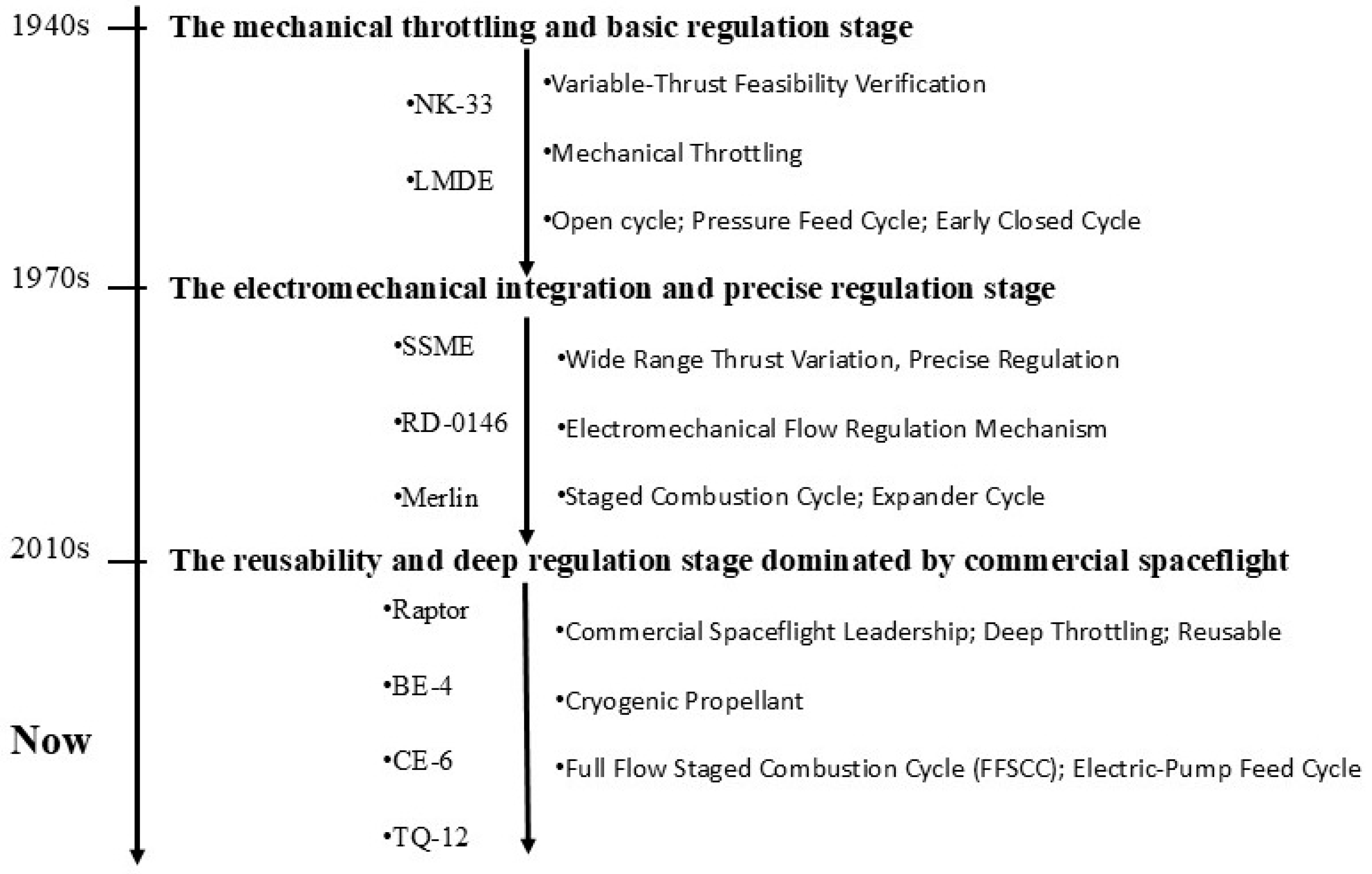
Figure 1. The development stages of variable-thrust liquid rocket engines.
Actuators 14 00385 g001
Figure 2. The Space Shuttle Main Engine (SSME) [25].
Actuators 14 00385 g002
Figure 3. Engine schematics of the LE-5B-2 engine [35].
Actuators 14 00385 g003
Figure 4. The Raptor engine system [42].
Actuators 14 00385 g004
Figure 5. Design schematic of electric-pump cycle [51].
Actuators 14 00385 g005
Figure 6. Schematic diagram of adjustable cavitating Venturi physical structure [60].
Actuators 14 00385 g006
Figure 7. Schematic diagram of pintle injectors [73].
Actuators 14 00385 g007
Figure 8. 40 klbf LOX/RP-1 engine cross section.
Actuators 14 00385 g008
Table 1. Selected variable-thrust liquid rocket engines and thrust regulation schemes.
EngineFlow Rate Regulation SchemesRegulation
Range
InjectorThrust Regulation Schemes
LMDEAdjustable cavitating Venturi tubes10~100%Pintle InjectorDouble regulation
SSMEThrottle Valve and Turbopump50~109%Coaxial InjectorSingle regulation
CECEBypass Valve and
Turbopump
10~100%Coaxial InjectorDouble regulation
TR-202Throttle Valve and Turbopump18.8~100%Pintle InjectorDouble regulation
7500 NAdjustable cavitating Venturi tubes20~100%Pintle InjectorDouble regulation
MorpheusElectric Motor and
Double Ball Valves
25~100%Impinging InjectorSingle regulation
Merlin-1DThrottle Valve and Turbopump75~100%Pintle InjectorDouble regulation
Disclaimer/Publisher’s Note: The statements, opinions and data contained in all publications are solely those of the individual author(s) and contributor(s) and not of MDPI and/or the editor(s). MDPI and/or the editor(s) disclaim responsibility for any injury to people or property resulting from any ideas, methods, instructions or products referred to in the content.