Article

Numerical Investigation of the Tribological Performance of Surface-Textured Bushings in External Gear Pumps Under Transient Lubrication Conditions

by
Paolo Casoli
1,*,
Masoud Hatami Garousi
1,
Massimo Rundo
2 and
Carlo Maria Vescovini
3
1
Department of Engineering for Industrial Systems and Technologies, University of Parma, 43124 Parma, Italy
2
Politecnico di Torino, Department of Energy, 10129 Turin, Italy
3
Casappa S.p.A., 43044 Parma, Italy
*
Author to whom correspondence should be addressed.
Actuators 2025, 14(7), 345; https://doi.org/10.3390/act14070345
Submission received: 5 June 2025 / Revised: 8 July 2025 / Accepted: 10 July 2025 / Published: 11 July 2025
(This article belongs to the Special Issue Advances in Fluid Power Systems and Actuators)

Abstract

This study presents a computational fluid dynamics (CFDs) investigation of the hydrodynamic behavior of surface-textured lateral bushings in external gear pumps (EGPs), emphasizing the effects of combined sliding and squeezing motions within the lubrication gap. A comprehensive numerical model was developed to analyze how surface texturing implemented through different dimple shapes and texture densities influences pressure distribution and load-carrying capacity under transient lubrication conditions. The analysis demonstrates that the interaction between shear-driven flow and squeeze-film compression significantly amplifies pressure, particularly when optimal dimple configurations are applied. Results indicate that dimple geometry, depth, and arrangement critically influence hydrodynamic performance, while excessive texturing reduces effectiveness due to increased average gap height. Cavitation was intentionally not modeled in the early single dimple evaluations to allow clear comparison between configurations. The findings offer a design guideline for employing surface textures to enhance tribological performance and efficiency in EGP applications under realistic dynamic conditions.

1. Introduction

External gear pumps (EGPs) are based on a simple mechanical concept, but the interaction of their internal components significantly complicates their design process. Among these internal components, the dynamic behavior of lateral bushings is critical to the performance and durability of EGPs. These bushings play an essential role in ensuring stable operation under varying conditions. Key to optimizing the performance of EGPs is a comprehensive understanding of the lubrication behavior within the lateral bushings, particularly the mechanisms of pressure generation under dynamic operating conditions. This requires analyzing how combined sliding and squeezing motions influence the formation and stability of the fluid film, which directly affects load-carrying capacity and pump reliability. Several studies have investigated the hydrodynamic behavior of lateral bushings, providing valuable insights into the complex interactions between surface motion, gap variation, and pressure development. Zardin et al. [1] developed a model to evaluate the hydro-mechanical efficiency of EGPs by analyzing friction losses in critical areas such as tooth tips, lateral gaps, and journal bearings. Their findings highlight the significant impact of lateral and meshing losses on the overall efficiency of the pump, particularly under low delivery pressures. Koç et al. [2] conducted an in-depth analysis of the lubrication mechanisms in bush-type bearings of high-pressure gear pumps, focusing on the behavior of the bushes and the clearances between gear end-faces and bushes. They found that bush lubrication is significantly influenced by surface irregularities on the gears and the non-flatness of the bushes, which affects hydrodynamic pressure generation. This study emphasizes the importance of achieving an optimal balance between sealing and lubrication under various operating conditions. Dhar and Vacca [3] developed a fluid–structure interaction (FSI) model to simulate the lubricating gaps in external gear machines (EGMs), focusing on elasto-hydrodynamic (EHD) effects. This model predicts the lubricant film thickness and is coupled with an axial balance model to determine the lateral bushing position under various operating conditions, providing a powerful tool for optimizing the equilibrium of EGP components. Torrent et al. [4] developed a comprehensive model to simulate and experimentally validate the movement of the floating bearing bushing in an EGP, focusing on its relation to pump parameterization. This model, enhanced by accounting for lubrication effects, was validated through laboratory and field tests, providing valuable insights into improving the pump volumetric efficiency and the equilibrium of the bushing. Further, Torrent et al. [5] introduced a novel approach to model the motion of floating bushings in EGPs using dimensional analysis, implemented through Bond Graph diagrams. This model, validated experimentally, offers a simple and fast tool for simulating the dynamic behavior of the floating bushing, making it a valuable resource for analyzing volumetric and mechanical efficiency variations under different operating conditions. Corvaglia et al. [6] employed three-dimensional CFDs simulations to evaluate tooth space pressure and detect flow rate reductions due to incomplete filling of the tooth spaces when inlet pressure is reduced. Their work validates the capability of CFDs models to accurately predict these parameters, providing insights into how manufacturing errors and lateral clearance can influence equilibrium conditions across the pump. Dhar and Vacca [7] further advanced the study of lateral bushings by introducing a novel modeling approach that couples CFDs with axial motion analysis to study the axial balance and lubricating gap of lateral bushings in external gear machines. Their work addresses the critical design challenge of maintaining efficient operation by ensuring proper sealing, minimizing power losses due to leakages, and maintaining full film lubrication to reduce wear. Thiagarajan et al. [8] investigated the lubrication performance of EGPs used in aerospace fuel delivery systems, focusing on the impact of frictional forces within the axial balance system. Their research demonstrated that frictional forces significantly affect the axial compensation system, influencing the lubricating gaps and thus the equilibrium conditions of the bushings, a factor crucial for the pump reliability and efficiency. It is important to explore methods for improving the load-bearing capacity of the lateral bushings. Surface texturing is one such method that has shown significant potential.
This approach falls into a wider scenario involving the study of the effect of the engineered surfaces on several phenomena. Microstructures on the surface could be an innovative method to mitigate cavitation erosion, as studied by Hu et al. [9], where the presented research provides the dimensional basis for designing cavitation-resistant surface microstructures. This aspect could be considered in future research to design cavitation-resistant surfaces, focusing on the part of a pump surface where cavitation could occur.
The potential of textured surfaces was also studied in completely different fields by Zhou et al. [10]. This research involves polymer coating in marine, machinery, and chemical applications to improve wear and corrosion resistance. In these cases, the surface textures reduce the hydrophilicity and minimize wear by trapping debris. This last citation is far from the application of this paper, but it aims to demonstrate the remarkable potential of investigating a designed surface.
Focusing on the fluid power applications and in particular on the EGP, by strategically applying textures to the bushing surfaces, the average pressure between moving surfaces can be increased, reducing friction and wear, and thus enhancing the overall load-bearing capacity. Shen and Khonsari [11] demonstrated that the shape and orientation of dimples on textured surfaces can lead to notable tribological improvements, including the “hollow” effect, where dimples store oil to prevent lubricant film failure. Furthermore, studies on surface texturing by Rahmani et al. [12] and Etsion et al. [13] demonstrated significant improvements in bearing performance through surface geometry optimization. Casoli et al. [14,15]. examined the performance improvements of EGPs through surface texturing, using CFDs simulations and bench tests. Their work explored the influence of geometric characteristics on bearing capacity, the impact of optimal dimple distribution, and the effects of cavitation between the dimples on load-carrying capacity. This paper extends previous studies by focusing on the hydrodynamic behavior within the suction-side lubrication gap of EGPs, considering the combined influence of sliding and squeezing motions between the gear side face and the lateral bushing (Figure 1). A key aspect of this interaction is the transient pressure development driven by simultaneous shearing flow and axial convergence of the gap, which strongly affects the load-carrying capacity and lubrication stability. Using a CFDs-based approach, this research systematically investigates how surface texturing, specifically the geometry of micro-dimples, modulates the pressure distribution and enhances hydrodynamic performance under realistic mixed-motion conditions. This study aims to identify optimal texturing strategies that maximize load support while maintaining pressure stability, providing design guidelines for improving the efficiency and durability of EGP components operating under transient lubrication regimes. In the next step of this research, will be to develop a pump prototype and perform endurance tests to assess whether the use of a textured surface improves the pump durability. In particular, tests on pumps with and without textured surfaces will permit us to measure both the global efficiency and the volumetric efficiency, while the hydromechanical efficiency will be computed. The volumetric efficiency will give us information about the leakages, while the hydromechanical efficiency information will give us information about the internal losses. The textured samples will be measured before the experimental tests, using an optical profilometer in order to verify that the geometry obtained by means of laser marking technology is the desired one. Then, at the end of the endurance test, the textured surface on the bushing will be checked again by means of the profilometer in order to verify the wear. Similar activity was already carried out with the previous prototype and reported in the cited work [15]. The experimental results reported in [15] support the validity of the adopted simulation approach; obviously, it is not possible to measure the fluid parameters inside the gap to directly validate the CFD analysis.

2. Models

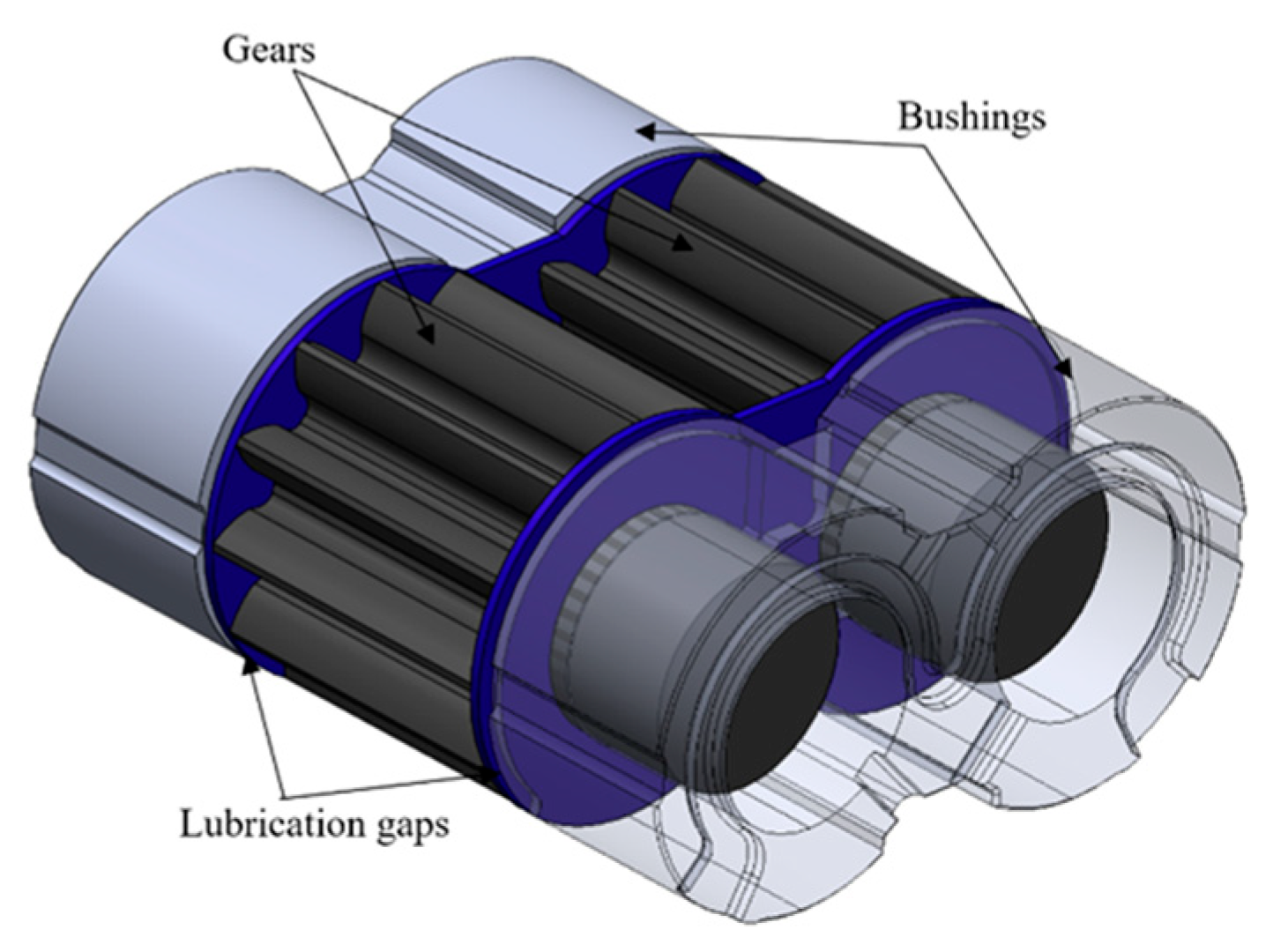
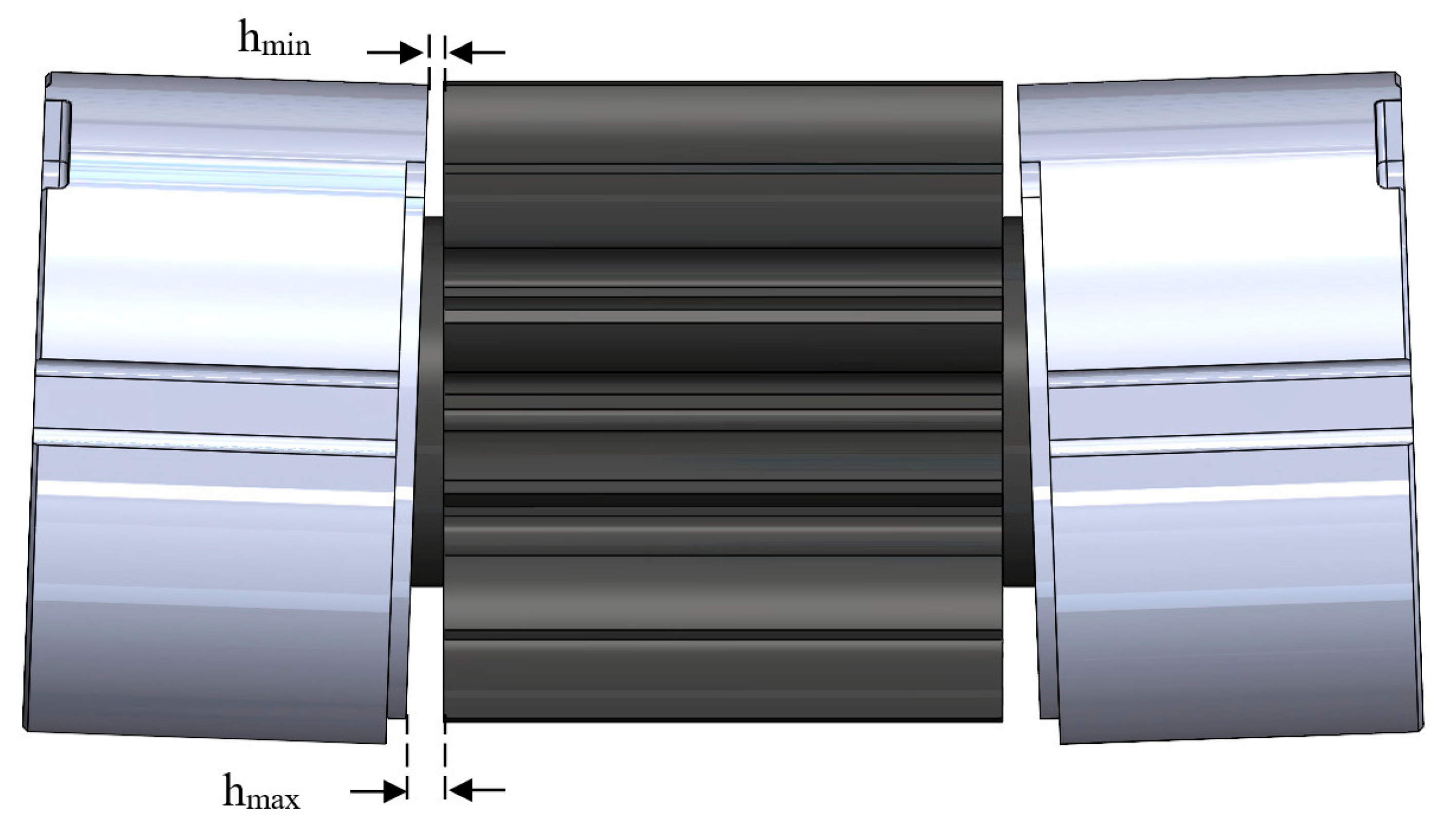
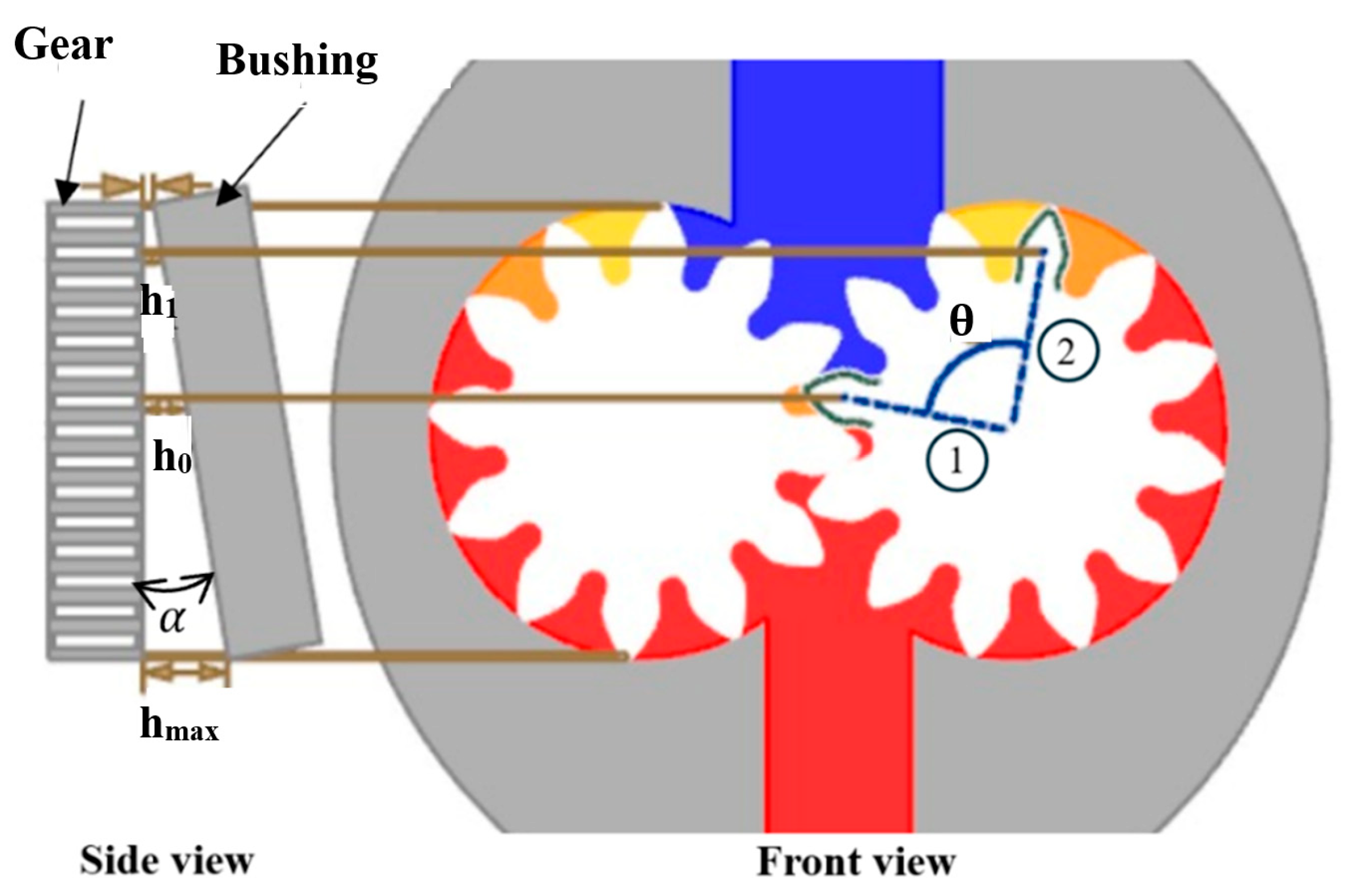
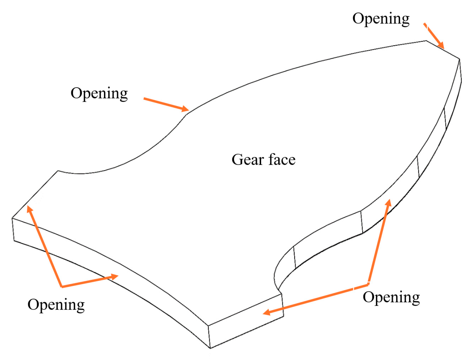
2.1. Bushing–Gear Interaction Model

The interaction of the lateral bushings, particularly on the suction side of an EGP, is critical for maintaining optimal lubrication under low-pressure conditions. Unlike the delivery side, the suction side operates where the clearance between the bushing and the gear is minimal. In some situations, this minimal clearance can lead to direct contact between the components, increasing the risk of wear. Therefore, the bushing ability to sustain a stable lubrication film is essential for minimizing wear and increasing the life of the EGP.
The instantaneous position of the lateral plates and, consequently, the lubrication gap between the bushing and the gear depends on the global forces acting on the lateral plates. Typically, the plates incline toward the low-pressure region, reducing the gap height in this area with respect to the gap height in the meshing zone. This reduction induces a squeeze effect, compressing the fluid and generating a reaction force.
The hydrostatic force balance drives the bushing toward the gear and tilts the bushing, [2,15]. As a result, the lubrication gap changes between its maximum (hmax) and minimum (hmin) values, as illustrated in Figure 2. Capturing these complex interactions is challenging but essential for optimizing system performance.

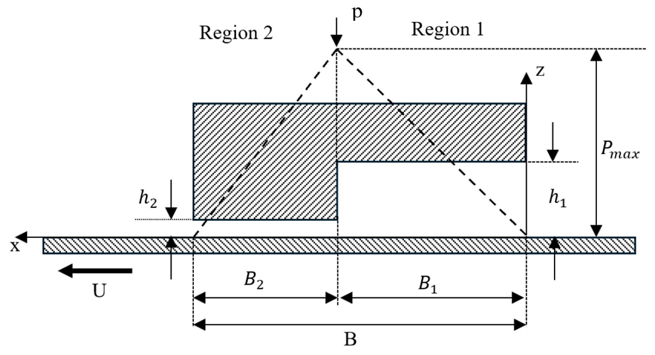
2.2. Computational Model

As shown in Figure 3, the gear tooth transitions from position 1 to position 2, corresponding to an angular displacement of approximately 90 degrees (θ in Figure 3). The lubrication gap between the bushing and the tip of the gear tooth varies between hmax on the high-pressure side (red color) and hmin on the low-pressure side (blue color). Using the tangent of the inclination angle (see Figure 3 side view), and the gear diameter, the corresponding gap heights at the center of the gear h0 and h1 (taken as reference) can be determined.
For confidential reasons, details about the gap heights are not reported, but as the gear rotates 90 degrees, the lubrication gap thickness decreases by approximately 6 μm. Furthermore, the time to reduce the gap is determined based on the rotational velocity of the EGP. As the rotational velocity increases, the squeezing effect becomes more obvious, generating higher hydrodynamic pressure within the lubrication film. This pressure buildup enhances the load-bearing capacity of the EGP, improving its overall performance and stability. To simulate the squeeze effect due to the gap reduction during rotation, as described, it has been assumed that the bushing moves toward the gear at a defined speed, from h0 to h1.
To identify the correct pressure distribution of the meatus (the lubrication gap between the gear face and lateral plate), the geometry of the meatus as shown in Figure 4 has been considered. As shown in Figure 5, a three-dimensional model of a single tooth is established, and based on these models, the boundary conditions have been defined.
Focusing on the suction side, the pressure is low; for this reason, an opening boundary condition with 1 bar absolute pressure is applied to the side walls. The rotational speed of the gear varies from a typical value for this kind of pump, assumed as a reference value to double of the reference value. The lubricating oil used in this study is a standard ISO VG46 grade, with a density of 850 kg/m3 and a dynamic viscosity of 0.039 Pa s at 50 °C. The geometric and operating parameters of the simulation model are presented in Table 1.

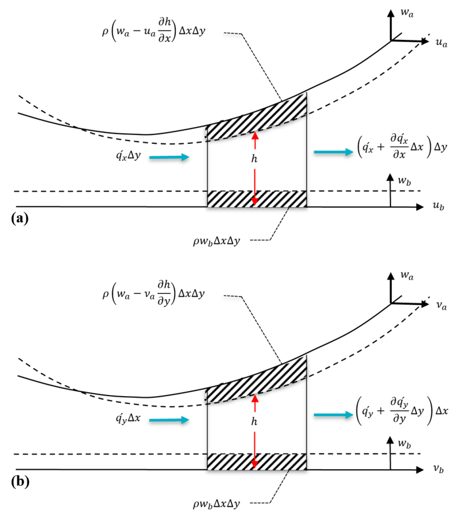
2.3. Governing Equations

The mechanisms generating hydrodynamic pressure within an oil film significantly impact the floating bushing motion and the system load-bearing capacity. These mechanisms are traditionally analyzed using the Reynolds equation.
Considering a three-dimensional bearing configuration, Figure 6, where the sliding motion in the x-direction is referred to as variable u while the squeeze motion in the z-direction is represented by the variable w, the Reynolds equation is as follows:
x ρ h 3 12 μ p x + y ρ h 3 12 μ p y + x ρ h u a + u b 2 + y ρ h v a + v b 2 + ρ ( w a w b ) ρ u a h x ρ v a h y + h ρ t = 0
where µ is the dynamic viscosity and ρ is the fluid density. In Equation (1) the first two terms are the Poiseuille terms and describe the flow rates due to pressure gradients, the third and fourth terms are the Couette terms and compute the flow rates due to the surface velocities, the fifth to seventh terms represent the flow rates due to squeeze effect, and the last term (local expansion) can be neglected as the fluid is assumed incompressible. The Couette terms can be expanded to analyze the distinct actions. The fluid density could be assumed constant because simulations are referred to the suction side, and, notwithstanding that the pressure can increase, the change in density is never above 0.5%; therefore, it has been assumed constant and the following equations are obtained:
x ρ h u a + u b 2 = ρ h 2 x u a + u b + ρ u a + u b 2 h x
y ρ h v a + v b 2 = ρ h 2 v v a + v b + ρ v a + v b 2 h y
The first term on the second right-hand is the stretch term; it is assumed to be null as the surface is a rigid body. Considering only one moving surface, with subscript a, and considering the term wa representative of the squeeze effect written as
w a = h t
the Reynolds equation becomes
x ρ h 3 12 μ p x + y ρ h 3 12 μ p y + ρ u a 2 h x + ρ v a 2 h y ρ u a h x ρ v a h y + ρ h t = 0
This equation is numerically solved by the software Ansys CFX©—2024.
This study is focused on parallel sliding surface with squeeze motion. The presence of a textured surface generated a physical wedge effect that together with the squeeze actions affect the pressure profile in the fluid film bearing. The presence of a textured surface affects the pressure distribution during the sliding motion; the presence of dimples generates sudden cross-sectional area variations causing pressure variations. The reference theory is based on the Rayleigh step bearing. Focusing on the cross-area reduction, and the consequent pressure increment in the gap, Figure 7, the Reynolds equation permits the prediction of the resultant pressure profile.
The governing equation for the parallel Rayleigh step bearing, considering the previously mentioned assumptions and neglecting the squeeze effect, is
d d x   h 3 μ d p d x = 6 U d h d x
where
h = h 1 0 x B 1 h 2 B 1 x B
In region 1, the film thickness is constant h = h1; therefore, the right-hand side of the Reynolds equation vanishes. The governing equation and the boundary conditions are as follows:
d d x   h 1 3 μ d p 1 d x = 0
p 1 = 0 a t   x = 0 p 1 = p C a t   x = B 1
In Equation (8) the parameter pC is common between the two regions 1 and 2 at the interface x = B1. By integrating Equation (8) and applying the boundary conditions, the expression for p1(x) is written as follows:
p 1 x = C 1 x
In region 2, the governing equation is
d d x   h 2 3 μ d p 2 d x = 0
p 2 = 0 a t   x = B p 2 = p C a t   x = B 1
By integrating Equation (8) and applying the boundary conditions, p2(x) is
p 2 x = C 3 x B
There are two unknown variables in Equations (9) and (11), which require two additional equations to be determined, as shown below:
p 1 = p 2 = p c   q 1 = q 2     a t   x = B 1
where q is the volumetric flow rate which is extracted from equation below:
h 1 3 12 μ d p 1 d x + U h 1 2 = h 2 3 12 μ d p 2 d x + U h 2 2
Finally, by considering these equations, the pressure profiles in regions 1 and 2 can be expressed as follows:
p 1 x = 6 μ U h 1 h 2 B 2 h 1 3 B 2 + h 2 3 B 1 x
p 2 x = 6 μ U h 1 h 2 B 1 h 1 3 B 2 + h 2 3 B 1 B x
Maximum values for p1(x) and p2(x) occur when x = B1, at this point the values of p1(x) and p2(x) are
p 1 B 1 = p 2 B 1 = 6 μ U h 1 h 2 B 2 h 1 3 B 2 + h 2 3 B 1 B 1 = 6 μ U h 1 h 2 B 1 h 1 3 B 2 + h 2 3 B 1 B 2
The computed pressure value is positive because h1 > h2 and U is a positive value in the direction of the x-axis. In a textured surface the interaction with the dimples also involves the sudden enlargement of the gap, which is like in Figure 7 assuming the sign of the velocity U is opposite. The previous equations remain valid, changing the sign of the velocity. The pressure must be the same on both sides, at different gap heights, at x = B1.
p 1 B 1 = p 2 B 1 = 6 μ U h 1 h 2 B 2 h 1 3 B 2 + h 2 3 B 1 B 1 = 6 μ U h 1 h 2 B 1 h 1 3 B 2 + h 2 3 B 1 B 2
In this case the pressure is negative but in magnitude it is equal to the value computed in Equation (15). Focusing only on the sliding effect, the mathematical analysis yields the conclusion that the dimples are not useful to increase the loading capacity; however, when analyzing a sequence of dimples, the scenario changes [14].
While Rayleigh step bearing theory provides important insight into pressure buildup in simplified geometries, it is not sufficient for modeling real surface textures involving multiple dimples in series. As shown in Figure 8, the pressure at the outlet of one dimple does not return to the inlet pressure due to cumulative losses, and analytical equations cannot capture this behavior without numerical integration. Therefore, CFDs are required to resolve the pressure field in such textured surfaces and to predict realistic force values under combined sliding and squeezing motions. A result obtained by CFDs code is presented [14]. In Figure 8 the presence of cavitation has not been considered, but in the real case, the pressure reduction could be limited by the onset of cavitation so the integral of the pressure over the surface could be higher.

2.4. Grid Independence Study

Achieving mesh independence is crucial for ensuring that the simulation results are reliable and unaffected by further refinement, thereby enhancing the accuracy of the numerical analysis. For the simulation, an element size of 0.02 mm was selected as the baseline, with particular attention given to the lubrication gap. Increasing the number of layers within the lubrication gap was found to significantly influence the calculated forces, while only minimally affecting the maximum velocity at the reference rotational speed. This phenomenon arises because the variation in the number of layers changes the mesh stiffness, thereby impacting the pressure distribution and the corresponding force predictions.
A dedicated mesh sensitivity study was conducted by varying the number of layers in the gap direction (5, 8, 10, and 12 layers) while keeping the element size constant. Due to mesh compression during the squeezing motion, the number of layers significantly affected the resolution of pressure and velocity gradients. Results showed that the hydrodynamic force varied by less than 2% between the 10- and 12-layer meshes, while the 8-layer mesh with y+ < 1 exhibited less than 6% deviation compared to the finest mesh. These findings confirm that the selected resolution offers sufficient accuracy for the transient lubrication analysis. To accurately capture flow behavior within the dimple cavities, a sweep meshing technique was employed to generate a structured mesh composed entirely of hexahedral elements. This approach provided consistent element topology throughout the thin lubrication gap and over the textured regions. Particular attention was devoted to mesh refinement in and around the dimples, ensuring a sufficient number of elements within each cavity to resolve potential recirculating and vortical flows. Inflation layers were applied along all solid surfaces to resolve the viscous sublayer and near-wall gradients. Mesh quality was carefully monitored using skewness and aspect ratio criteria to ensure numerical stability and physical accuracy. The effect of grid refinement on simulation outputs is summarized in Table 2. Based on the analysis of accuracy, flow resolution, and computational cost, the 8-layer mesh was selected as the final configuration. The resulting mesh structure is illustrated in Figure 9.

3. Results and Discussion

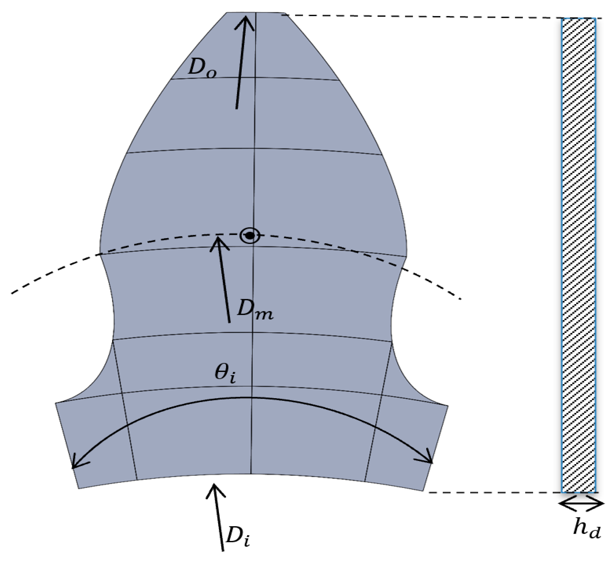
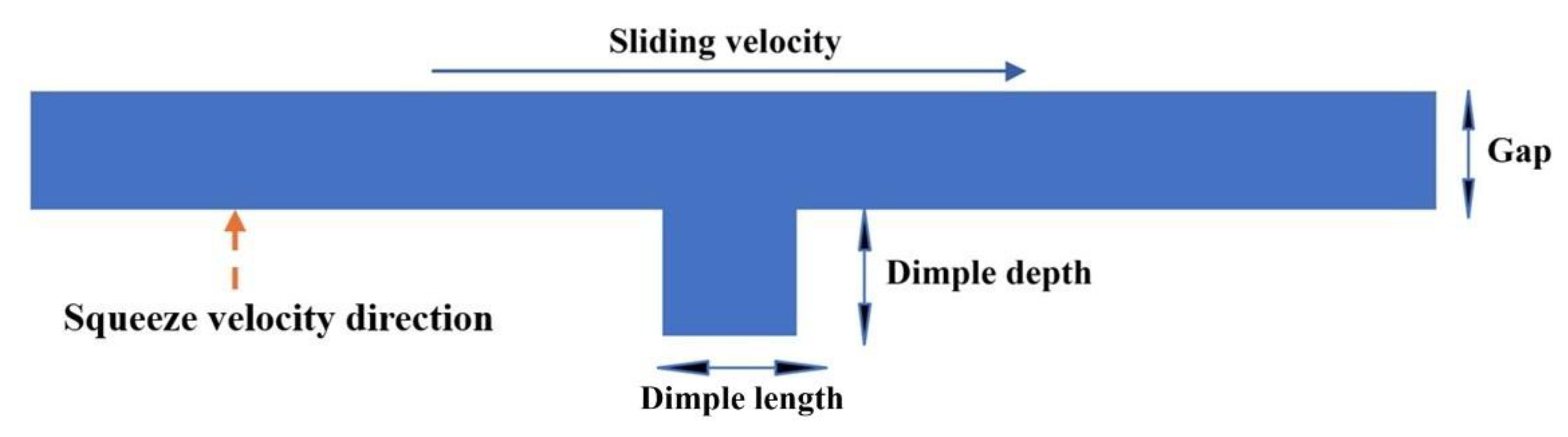
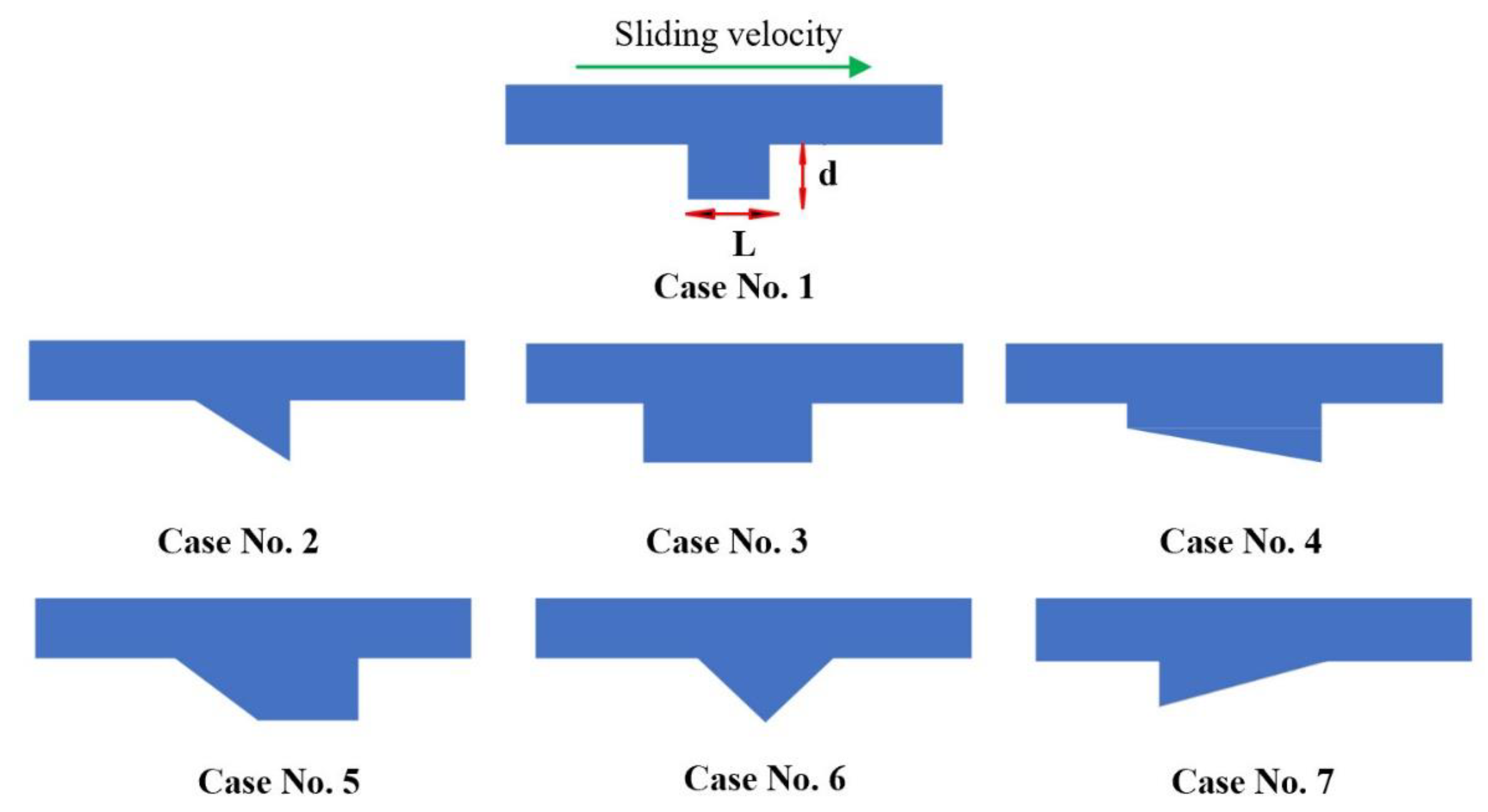
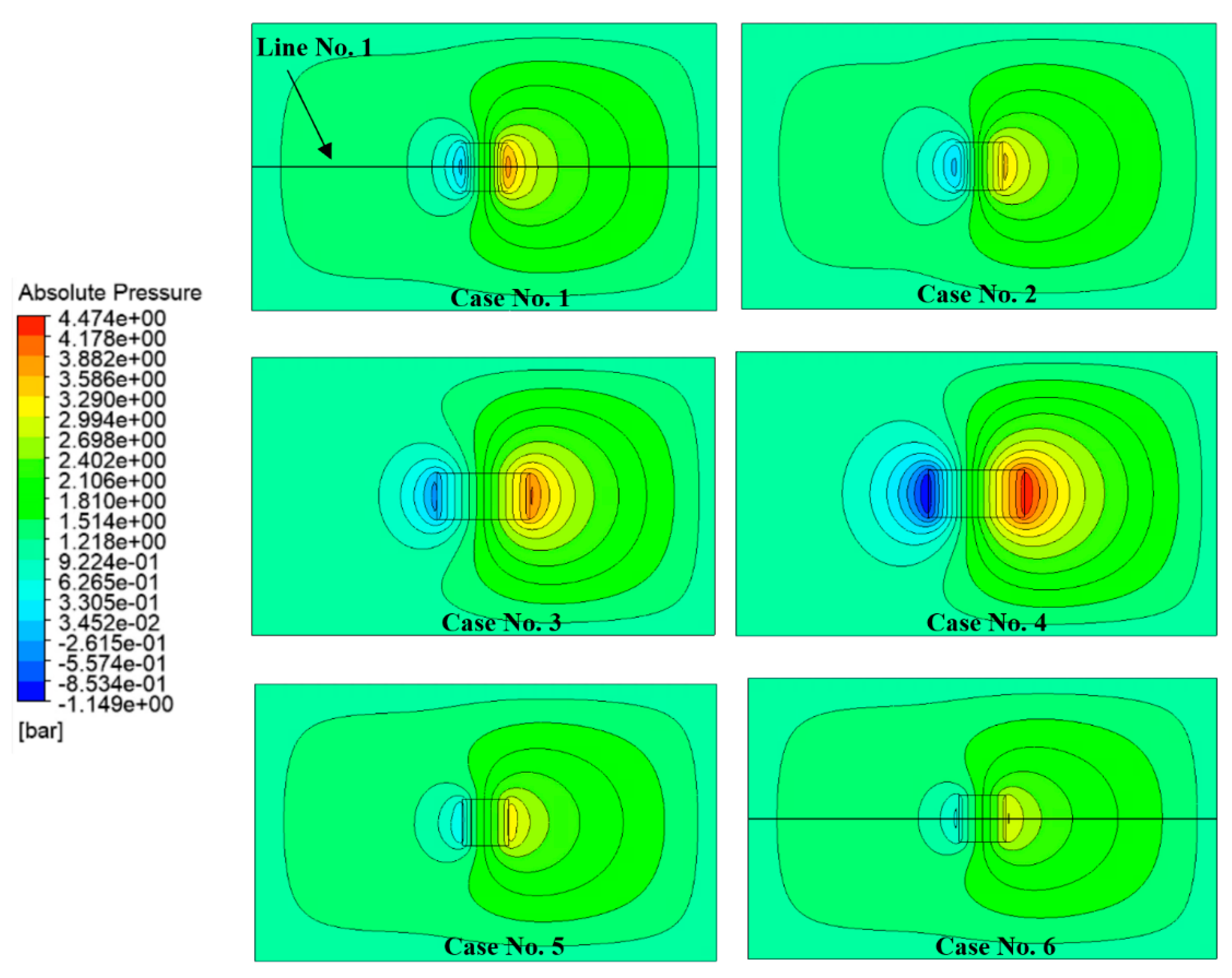
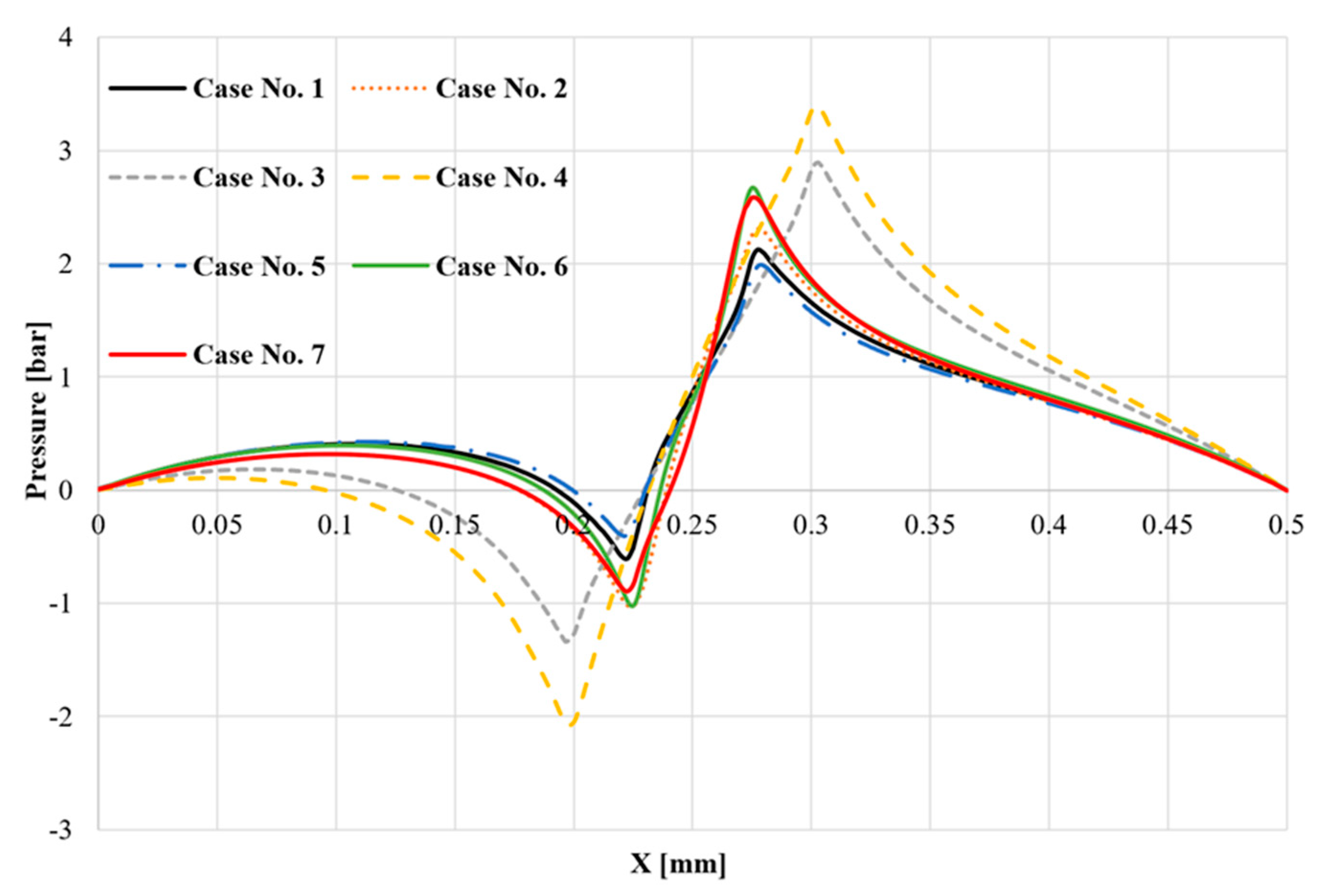
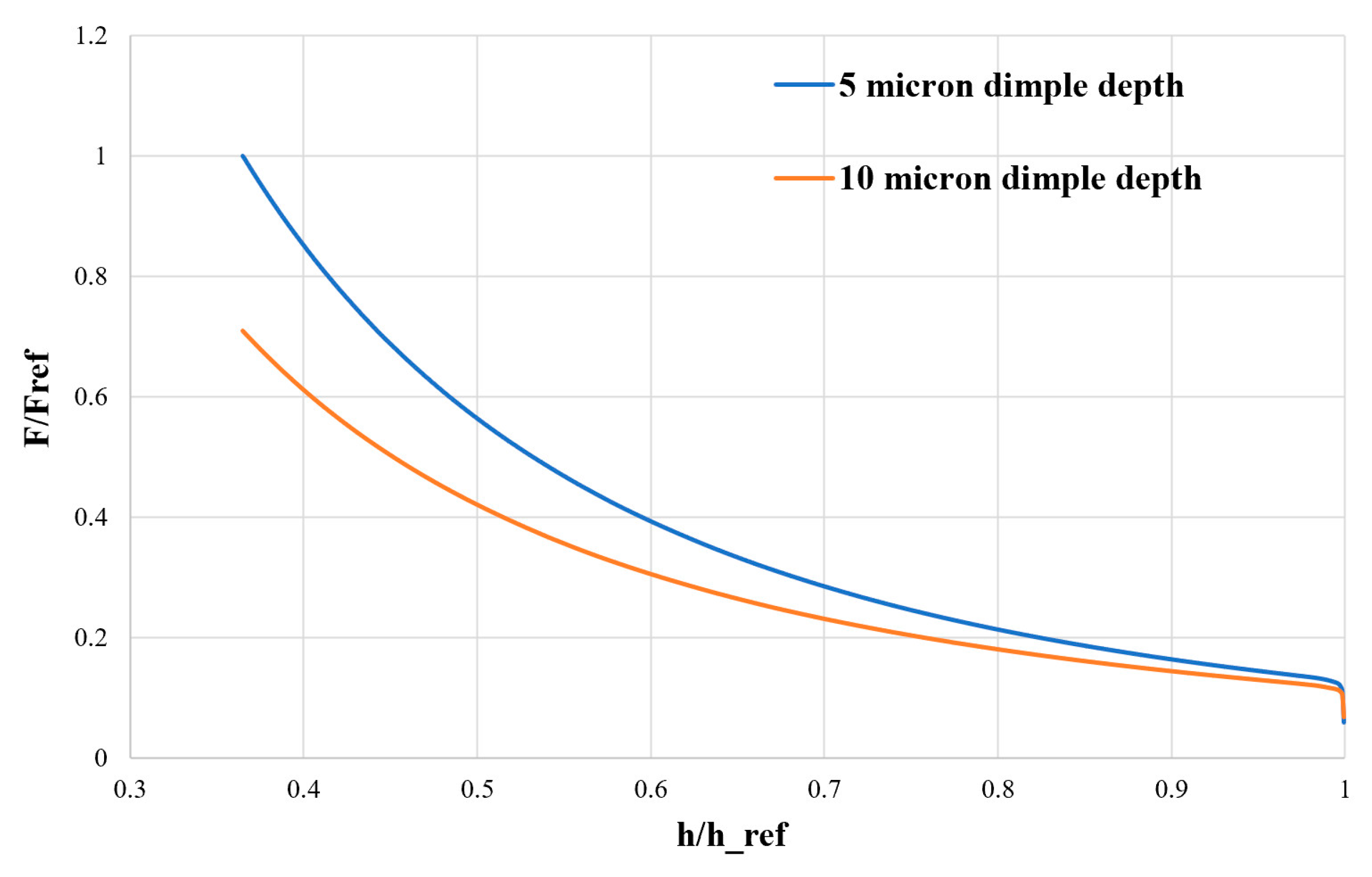
3.1. Optimum Dimple Geometry

This section investigates the effect of different dimple geometries on pressure generation and load-carrying capacity using CFDs simulations under combined sliding and squeezing conditions. The goal is to identify optimal dimple configurations that enhance pressure buildup and load support under these mixed-motion regimes. This study builds on earlier research by the authors [12] and extends the analysis to better reflect operating conditions found in practical applications.
To evaluate the influence of dimple geometry on hydrodynamic performance, a rectangular fluid domain was defined with dimensions of 600 µm in width, 1000 µm in length, and an initial gap height of about 9 μm (Figure 10). A single dimple was placed at the center of this domain, and seven different dimple shapes were individually tested. This setup allows for a direct comparison of how each geometry affects the pressure distribution and load-carrying capacity within the lubrication film. Figure 11 shows the different dimple shapes.
Figure 11 presents the seven dimple geometries investigated under identical conditions. While the dimple lengths vary across the configurations (100–200 μm), as detailed in Table 3, the dimple width (perpendicular to the plane of the Figure 11, W) is kept constant at 100 µm and dimple depth changes according to the Table 3.
To ensure the accuracy and reliability of the CFDs results, a mesh independence study was performed. A structured mesh was used throughout the domain to maximize numerical stability and solution accuracy, particularly in the region around the dimple where high pressure gradients are expected. For the mesh refinement strategy, multiple layers were introduced within the dimple depth to adequately resolve the near-wall gradients and capture the local flow phenomena. The number of layers varied slightly to accommodate the different cases studied, the base element size was kept constant across all dimple configurations to ensure consistency in spatial resolution and to isolate the effects of geometry from those of the mesh. The mesh was refined close to the dimple edges within the lubrication gap to accurately capture pressure variations without excessively increasing computational cost. For the simulation setup, a zero-pressure boundary condition was applied to the side walls. The upper surface was defined as the sliding wall, moving at a constant velocity of 4 m/s to represent the Couette-driven shear flow. Simultaneously, the lower surface was assigned a vertical motion to simulate the squeeze effect, compressing the lubrication gap about 6.0 µm at a constant speed of 0.72 mm/s. All other boundaries were treated as stationary with no-slip conditions. Figure 12 shows the pressure contour around the dimples at the final minimum gap height.
Modifying the dimple shape to introduce a sloped surface of the base, either in the direction of motion or against it, does not lead to significant changes in the overall pressure distribution. However, increasing the dimple length along the direction of sliding results in a higher-pressure amplitude within the lubrication film. This increases both the positive and negative pressure regions, thereby increasing the chance of cavitation onset due to localized pressure drops below saturation levels. For more details, a line at the middle of the dimple width (Line No. 1) and on the face of the sliding plane has been considered and the pressure on that line has been calculated and is shown in Figure 13.
Figure 13 shows the pressure distribution along the sliding direction for seven different dimple configurations under combined sliding (4 m/s) and squeezing (0.72 mm/s) conditions. The pressure profiles demonstrate the influence of dimple geometry on the fluid film behavior within the lubrication gap, where both Couette-driven shear flow and squeeze-induced compression interact to generate complex pressure patterns. Case 3 and Case 4 exhibited the highest positive pressures of 2.83 bar and 3.4 bar, respectively, but also showed deep negative pressures down to −1.3 bar and −2.02 bar, suggesting a higher risk of cavitation. These sharp drops in pressure result from their longer or more aggressive dimple geometries, which intensify flow disturbance in the diverging zones. On the other hand, Cases 2, 6, and 7 show smoother transitions but lower pressure amplification, suggesting weaker hydrodynamic support. Case 1 shows a good balance between generating high pressure and keeping the flow stable. It creates strong positive pressure while avoiding very deep negative pressure, which helps support more load and reduces the risk of cavitation. Case 5 behaves in a similar way, but with slightly lower pressure peaks and smaller negative pressures. This makes Case 5 a good alternative, especially in situations where avoiding negative pressure is more critical than achieving the highest-pressure peaks. Based on these results, Case 1 was selected as the optimal configuration; as it produced a balanced profile with a peak pressure of 2.1 bar and a minimum of –0.31 bar, it was chosen for further analysis because it offers the best balance between load support and pressure stability. However, Case 5 is also a strong candidate, with similar behavior and a slightly gentler pressure profile, which could help reduce the chance of cavitation in more sensitive conditions.
Concerning Case no. 1 in Figure 14, the velocity vectors within the gap are shown. Due to the very low hydraulic diameter and high fluid viscosity, the flow is laminar, characterized by a very low Reynolds number. As illustrated in Figure 14, fluid recirculation occurs near the dimple enlargement and contraction, while the highest velocities are concentrated near the sliding wall.
All the simulations, Figure 12 and Figure 13, were performed without considering the cavitation model. This was an intentional decision aimed at identifying which configurations can generate strong negative pressures under combined sliding and squeezing conditions. As noted in previous work [14], the imposition of a minimum saturation pressure, such as through a cavitation model, causes many configurations to converge to the same minimum pressure, making it difficult to differentiate their performance. By keeping cavitation inactive in this study, the pressure profiles of individual designs could be assessed more clearly. In the following simulations, negative pressure has never been reached because of the simulation conditions and texturized surface considered, so the cavitation model should not be considered.

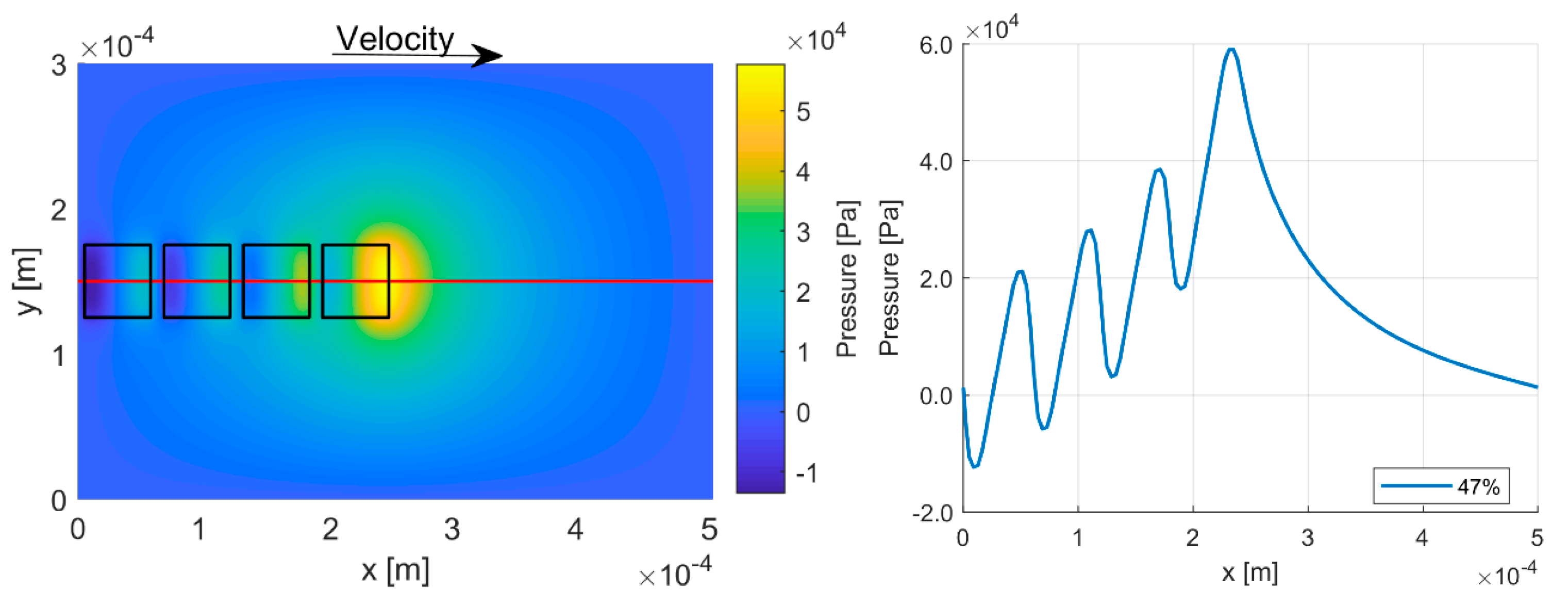
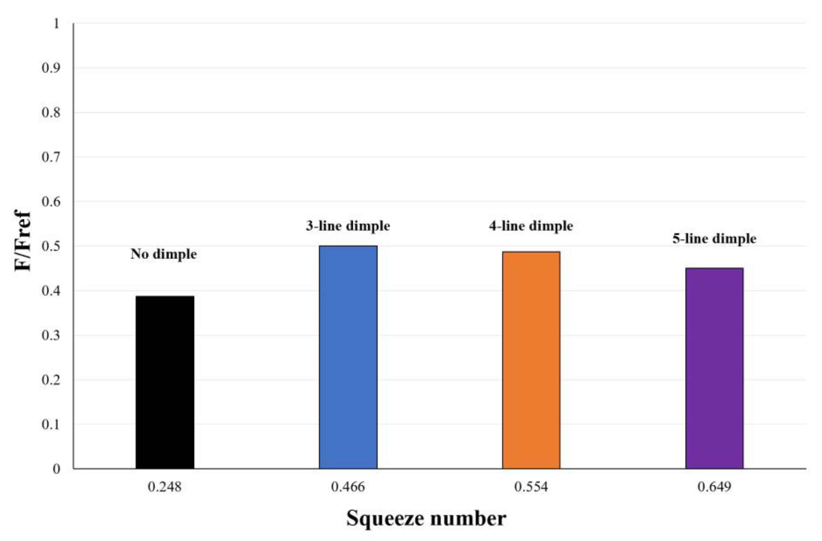
3.2. Texturing of the Surface

In previous work by the authors [14,15], it was demonstrated that partial surface texturing offers better performance than full texturing in terms of hydrodynamic pressure generation. However, the analysis was limited to pure sliding conditions. In this section, both sliding and squeezing effects are considered to provide a more realistic evaluation of surface behavior in dynamic applications.
Figure 15 illustrates the configuration utilized for evaluating partial surface texturing. Based on the findings from the previous analysis (Case No. 1), the dimple dimensions were selected as 100 µm × 100 µm. The textured region depicted in Figure 15 spans a 10-degree angular sector. To closely simulate actual operating conditions, the lubrication gap was displaced about 6 µm, effectively simulating the squeeze motion. Additionally, a sliding velocity corresponding to a reference rotational speed (nref) was imposed on the rotating surface. Under these conditions, the calculated squeezing velocity of the bushing was approximately 0.72 mm/s. Figure 16 shows the pressure distribution for the single portion at the final minimum gap height and dimple depth of 5 µm.
In Figure 16 the pressure distributions refer to three different conditions: (a) sliding only, (b) squeezing only, and (c) combined sliding and squeezing. In (a), the pressure buildup follows the theory of a parallel Rayleigh step bearing, where the presence of dimples induces localized pressure increase due to sudden cross-sectional changes along the flow direction. In (b), only the squeeze effect is applied, and the pressure generation is governed by the unsteady Reynolds equation, resulting in a more uniform pressure rise due to fluid compression. The pressure distribution in this case is maximal where the gap height is the minimum. As a matter of fact, the presence of the dimples generates a higher average gap height in respect to the flat surface. In (c), both sliding and squeezing motions are combined, leading to a significant enhancement in peak pressure due to the superposition of hydrodynamic and squeeze-film effects. For more details, the hydrodynamic force acting on the sliding plane under three different motion conditions of sliding only, squeezing only, and combined sliding and squeezing has been calculated and is shown in Figure 17. For confidentiality reasons, in portion texturing, the force was normalized with respect to the maximum value.
Figure 17 shows that the squeeze motion generates a higher force than the sliding motion alone, confirming its dominant role in pressure buildup under transient conditions. Furthermore, the superposition of sliding and squeezing leads to a significantly amplified force compared to each mechanism in isolation, illustrating the interaction predicted by the Reynolds equation. These results highlight the importance of considering both motions when designing textured surfaces to enhance load support. To further examine how surface texture parameters affect the combined sliding and squeezing behavior, the influence of dimple depth was investigated. Two different dimple depths, 5 µm and 10 µm, were analyzed using the configuration illustrated in Figure 15.
Figure 18 shows the non-dimensional hydrodynamic force acting on the sliding surface as a function of the dimensionless gap height for two different dimple depths of 5 µm and 10 µm, as the stationary bushing moves about 6 µm towards the rotating surface. The gap height is normalized by its initial value. The shallower dimples (5 µm) act as more effective steps, enhancing pressure buildup due to sudden cross-sectional changes in the flow path. In contrast, deeper dimples (10 µm) introduce larger fluid expansion zones and increase the average gap height, which reduces the efficiency of pressure buildup and lowers the overall load-carrying capacity. These findings confirm that optimizing dimple depth is critical for improving performance under transient lubrication conditions. Figure 19 and Figure 20 show the pressure distributions in different texturing configurations for the reference rotational speed (nref) and for double the reference rotational speed (2nref), respectively.
Figure 19 and Figure 20 show the absolute pressure contours for three different partial texturing configurations (three, four, and five-line dimple patterns) at two rotational speeds. While the peak pressure slightly increases with the number of dimple lines, the primary distinction lies in the spatial distribution of the pressurized region. In the five-line configuration, high-pressure zones are more localized and fragmented, whereas the three-line configuration exhibits broader and more continuous pressurized areas. This indicates that the three-line arrangement results in a higher integrated pressure over the surface, which contributes to greater load-carrying capacity. At the lower rotational speed (nref), a similar trend is observed, though absolute pressure values are reduced due to the lower sliding velocity and weaker squeeze effect. Nonetheless, the spatial extent of the high-pressure zones remains more pronounced in configurations with fewer dimple lines. These results suggest that while increasing dimple density may enhance local pressure peaks, it does not necessarily translate into higher load support. Instead, an optimal, moderately spaced texture pattern, such as the three-line configuration, yields a more favorable pressure distribution for hydrodynamic performance.
In order to generalize the findings, a dimensionless parameter named squeeze number, which is a modified Reynolds number, has been used, it is defined as follows:
σ s = ρ u h 2 μ l
where u is the sliding velocity; h is the gap height; and l is the length in the direction of sliding. The hydrodynamic force, obtained by integrating the pressure over the surface of the sliding wall, is presented in Figure 21 and Figure 22 as a function of the squeeze number for rotational speeds of nref and 2nref, respectively. The squeeze number is evaluated based on the minimum gap height reached during the simulation. The average gap height used in Equation (17) is calculated from the volume of the fluid within the lubrication gap, at minimum gap height, which varies depending on the number of dimples present on the surface.
Figure 21 and Figure 22 illustrate the non-dimensional hydrodynamic force as a function of the squeeze number for three different surface texturing configurations, corresponding to 3-line, 4-line, and 5-line dimple patterns for two rotational speeds of nref and 2nref, respectively. These plots highlight how texturing density influences pressure buildup under transient lubrication conditions dominated by squeeze motion. At both speeds, the configuration with three lines of dimples consistently generates the highest hydrodynamic force. This behavior suggests the presence of an optimal texture density that maximizes pressure buildup without significantly increasing the average fluid film thickness. As the number of dimple rows increases, the average gap height also increases, which weakens the effectiveness of squeeze-induced pressure generation. While increasing the dimple density (from 3 to 5 lines) leads to a slight rise in peak pressure (as seen in Figure 18 and Figure 19), the integrated pressure (force) over the surface declines. This effect is more significant at higher rotational speed, Figure 22, where the squeeze mechanism is more dominant. These results confirm that excessive texturing can diminish the hydrodynamic performance of the system. Therefore, identifying an optimal balance between dimple density and effective film thickness is essential for enhancing load support.

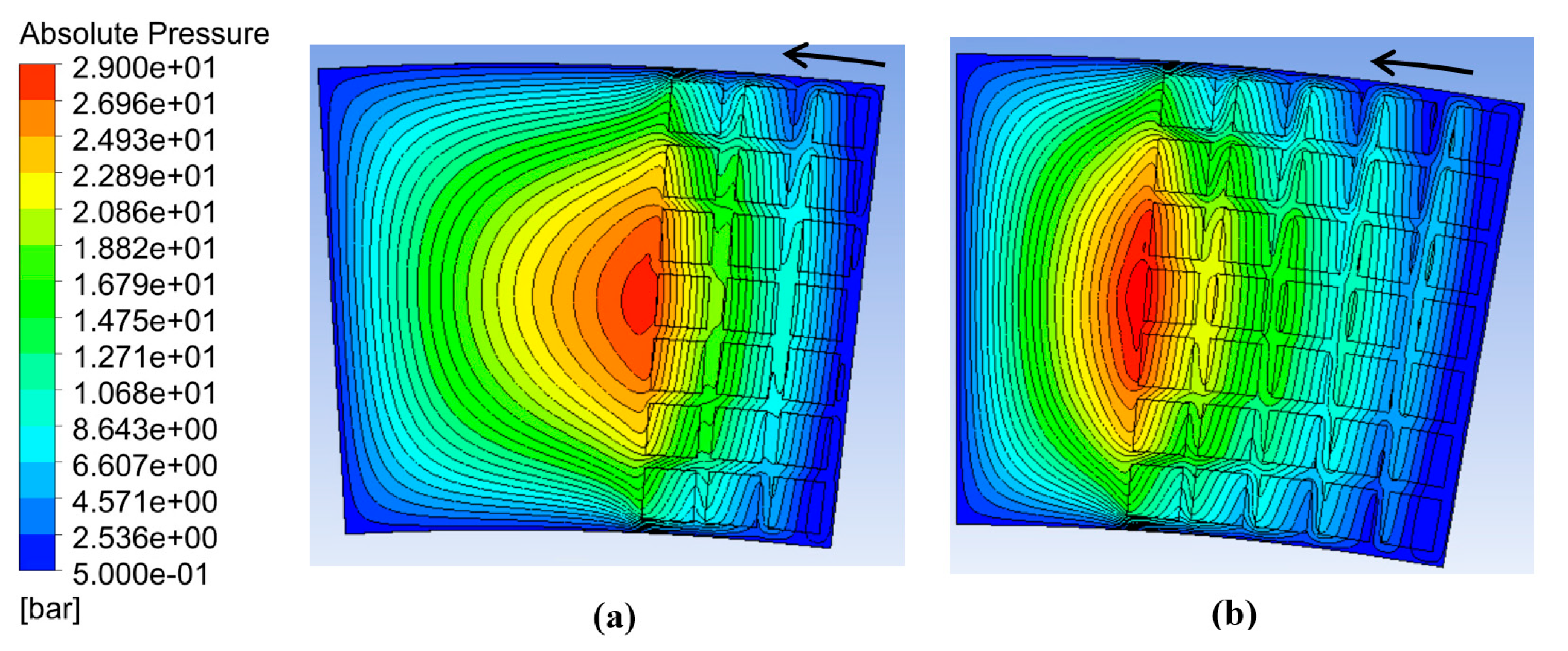
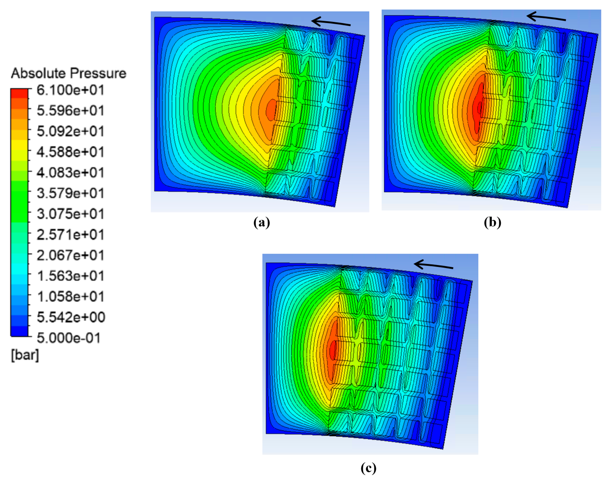
3.3. Modeling of the Interaction Between Texturized Bushing and Tooth

To evaluate the impact of surface texturing under realistic operating conditions, this study extended the analysis from simplified domains to the full three-dimensional geometry of the bushing–gear interface. Simulations incorporated both the sliding motion from gear rotation and the squeezing motion due to bushing displacement. This coupled configuration introduces shear-driven (Couette) and compression-driven (squeeze-film) flow components, replicating actual operating behavior. Building upon this framework, the following analyses explore how different texturing configurations and rotational speeds influence the load-bearing capacity of the external gear pump under combined motion conditions. Figure 23 and Figure 24 show the corresponding pressure contours for various configurations at rotational speeds of nref and 2nref, respectively.
Figure 23 and Figure 24 show key trends in pressure distribution influenced by dimple arrangement and rotational speed. The density of the dimples plays a crucial role in shaping the pressure field, in a similar manner to what was found in Figure 21. An additional observation is that maximum pressure occurs near the center of the gear, where the fluid is less likely to escape, allowing it to become trapped within the dimples, thereby enhancing load support. Furthermore, increasing the rotational speed leads to higher peak pressures, owing to intensified shear and squeeze interactions. The resulting forces on the tooth face for each configuration versus the squeeze number are summarized in Figure 25 and Figure 26. For confidentiality reasons the force was normalized with respect to the maximum value.
Figure 25 and Figure 26 show the variation of the hydrodynamic force on the gear tooth surface as a function of the squeeze number for three different partial texturing configurations, three-line, four-line, and five-line dimple arrangements under two rotational speeds, nref and 2nref, respectively. At both speeds, the configuration with three lines of dimples produces the highest hydrodynamic force. This suggests that a 3-line dimple density provides the most favorable balance between effective fluid film modulation and pressure generation through the squeeze-film effect. As the number of dimples increases (four and five lines), the average fluid volume in the gap rises, leading to reduced pressure buildup and, consequently, lower hydrodynamic force. The difference in performance among configurations becomes more evident at the higher speed condition (2nref), where the squeeze and shear interactions are more noticeable.
Finally, these results demonstrate that surface texturing can significantly influence the transient lubrication behavior of gear tooth and that optimizing dimple arrangement and density is essential for improving tribological performance under dynamic conditions.

4. Uncertainty and Limitations

The following sources of uncertainty were identified in the current numerical study.
  • Numerical discretization (mesh)
A mesh convergence study was conducted using 5, 8, 10, and 12 layers and an element size of 0.02 mm in the lubrication gap (Section 2.4). The difference in predicted hydrodynamic force between the 10- and 12 -ayer meshes was less than 2%, indicating acceptable spatial discretization error. The final simulations used an 8-layer structured mesh, which showed <5% deviation from the most refined mesh, providing a balance between accuracy and computational cost.
  • Temporal discretization (time step)
Time step sensitivity was assessed by changing the reference time step (1 × 10⁻⁶) in selected transient simulations. The residual target in continuity and momentum equations remained below 1 × 10⁻⁶, confirming the time resolution was adequate to capture transient squeeze behavior.
  • Model assumptions
The analysis referred to the suction side of pump, and the simulation started at very low pressure; fluid pressure in the gap can increase as shown during rotation. Thermal effects such as local heating due to viscous shear and heat exchange with the walls are neglected, assuming the fluid isothermal. These little simplifications respecting the complexity of computing these effects, have no relevant effect on density and viscosity because the temperature variations should be very little anyway.
Cavitation has never been considered. In the first step of analysis focused on the single dimple, cavitation was neglected for identifying which configurations can generate strong negative pressures under combined sliding and squeezing conditions; as a matter of fact, to limit the minimum pressure to a saturation pressure would hide the performance of the single dimple in all the cases considered. In all the other simulations presented, referring to portion and tooth, cavitation does not occur; starting from an absolute pressure of 1 bar, the pressure never reaches the saturation value because of the squeezing motion that generates a general pressure increment, compensating the pressure decrement associated with the sliding motion and dimples.
  • Model Validation
Due to the extremely narrow lubrication gap and the inaccessibility of internal flow measurements, direct experimental sampling of pressure or velocity is not feasible. In future investigations, a physical prototype will be developed to assess the impact of surface texturing on pump performance. The validation will focus on comparing the global and volumetric efficiency of the pump with and without the textured bushing. This approach allows for an indirect but meaningful assessment of the simulation predictions in terms of overall performance improvements. A similar approach was presented in a previous work [15].

5. Conclusions

This study presented a numerical investigation of the tribological behavior of surface-textured bushings in external gear pumps under transient lubrication conditions. A three-dimensional CFDs-based approach was employed to evaluate how different dimple geometries, depths, and configurations influence the generation of hydrodynamic force during combined sliding and squeezing motion. The results demonstrate that the presence and design of surface texturing significantly affect the pressure buildup and force response under dynamic operating conditions. Among the tested dimple depths, shallower dimples (5 µm) generated higher hydrodynamic forces, especially as the gap height decreased. This behavior was attributed to the step-bearing effect, where shallower dimples enhanced the squeeze-film action due to stronger pressure gradients. Additionally, partial texturing configurations applied to the gear tooth surface were evaluated under two rotational speeds. It was found that a 3-line dimple density resulted in higher hydrodynamic forces compared to denser configurations. As the number of dimples increased, the average fluid volume in the gap rose, reducing the effectiveness of the squeeze mechanism. The influence of dimple configuration became more noticeable at higher rotational speeds, further emphasizing the role of optimized surface texturing in enhancing performance. Overall, the findings suggest that careful tuning of both dimple depth and texture density is essential for maximizing load support in dynamically lubricated systems. The findings provide a scientifically grounded framework for the design of engineered surfaces in dynamic interaction between the bushing and the teeth, contributing to improved mechanical efficiency and durability of gear pump systems.

Author Contributions

Conceptualization, P.C. and M.R.; methodology, M.H.G., P.C. and C.M.V.; software, M.H.G.; validation, M.H.G., C.M.V. and P.C.; writing—original draft preparation, P.C. and M.H.G.; writing—review and editing, P.C. and M.R.; supervision, P.C.; project administration, P.C. All authors have read and agreed to the published version of the manuscript.

Funding

This research received no external funding.

Data Availability Statement

The original contributions presented in the study are included in the article, further inquiries can be directed to the corresponding author.

Acknowledgments

The authors would like to acknowledge the active support provided for this research by Casappa S.p.A., Parma, Italy.

Conflicts of Interest

Author Maria Vescovini was employed by the company Casappa S.p.A. The remaining authors declare that the research was conducted in the absence of any commercial or financial relationships that could be construed as a potential conflict of interest.

References

  1. Zardin, B.; Natali, E.; Borghi, M. Evaluation of the Hydro—Mechanical Efficiency of External Gear Pumps. Energies 2019, 12, 2468. [Google Scholar] [CrossRef]
  2. Koç, E.; Ng, K.; Hooke, C.J. An Analysis of the Lubrication Mechanisms of the Bush-Type Bearings in High Pressure Pumps. Tribol. Int. 1997, 30, 553–560. [Google Scholar] [CrossRef]
  3. Dhar, S.; Vacca, A. A Fluid Structure Interaction—EHD Model of the Lubricating Gaps in External Gear Machines: Formulation and Validation. Tribol. Int. 2013, 62, 78–90. [Google Scholar] [CrossRef]
  4. Torrent, M.; Gamez-Montero, P.J.; Codina, E. Model of the Floating Bearing Bushing Movement in an External Gear Pump and the Relation to Its Parameterization. Energies 2021, 14, 8553. [Google Scholar] [CrossRef]
  5. Torrent, M.; Gamez-Montero, P.J.; Codina, E. Motion Modelling of the Floating Bushing in an External Gear Pump Using Dimensional Analysis. Actuators 2023, 12, 338. [Google Scholar] [CrossRef]
  6. Corvaglia, A.; Rundo, M.; Casoli, P.; Lettini, A. Evaluation of Tooth Space Pressure and Incomplete Filling in External Gear Pumps by Means of Three-Dimensional CFD Simulations. Energies 2021, 14, 342. [Google Scholar] [CrossRef]
  7. Dhar, S.; Vacca, A. A Novel CFD—Axial Motion Coupled Model for the Axial Balance of Lateral Bushings in External Gear Machines. Simul. Model. Pract. Theory 2012, 26, 60–76. [Google Scholar] [CrossRef]
  8. Thiagarajan, D.; Vacca, A.; Watkins, S. On the Lubrication Performance of External Gear Pumps for Aerospace Fuel Delivery Applications. Mech. Syst. Signal Process 2019, 129, 659–676. [Google Scholar] [CrossRef]
  9. Ren, Q.N.; Hu, H.X.; Zheng, Y.G. Effect of surface microstructure spacing on the cavitation erosion process of stainless steel. Wear 2024, 558–559, 205542. [Google Scholar] [CrossRef]
  10. Yan, J.; Rong, Y.; Zhang, Y.; Zhou, S.; Huang, J.; Zhao, G.; Liu, Y. Wear and corrosion resistance of textured and functionally particle-enhanced multilayer dual-biomimetic polymer coatings. Tribology Int. 2025, 202, 110335. [Google Scholar] [CrossRef]
  11. Shen, C.; Khonsari, M.M. Effect of Dimple’s Internal Structure on Hydrodynamic Lubrication. Tribol. Lett. 2013, 52, 415–430. [Google Scholar] [CrossRef]
  12. Rahmani, R.; Mirzaee, I.; Shirvani, A.; Shirvani, H. An Analytical Approach for Analysis and Optimisation of Slider Bearings with Infinite Width Parallel Textures. Tribol. Int. 2010, 43, 1551–1565. [Google Scholar] [CrossRef]
  13. Etsion, I.; Halperin, G.; Brizmer, V.; Kligerman, Y. Experimental Investigation of Laser Surface Textured Parallel Thrust Bearings. Tribol. Lett. 2004, 17, 295–300. [Google Scholar] [CrossRef]
  14. Casoli, P.; Scolari, F.; Rundo, M.; Lettini, A.; Rigosi, M. CFD Analyses of Textured Surfaces for Tribological Improvements in Hydraulic Pumps. Energies 2020, 13, 5799. [Google Scholar] [CrossRef]
  15. Casoli, P.; Scolari, F.; Vescovini, C.M.; Rossi, C.; Lettini, A. Analyses of Engineered Surfaces for Performance Improvements of External Gear Pumps. In Proceedings of the Global Fluid Power Society PhD Symposium, Naples, Italy, 12–14 October 2022; River Publishers: Alsbjergvej, Denmark, 2024. ISBN 9788770047975. [Google Scholar] [CrossRef]
  16. Kennedy, F.E. Applied Tribology: Bearing Design and Lubrication. J. Tribol. 2002, 124, 428. [Google Scholar] [CrossRef]
Figure 1. Lubrication gap between bushings and gears in EGPs.
Actuators 14 00345 g001
Figure 2. Characteristic shape of the gear–bushing gap.
Actuators 14 00345 g002
Figure 3. Schematic of the tooth movement in the suction side.
Actuators 14 00345 g003
Figure 4. Geometry of a single tooth and the gap height hd.
Actuators 14 00345 g004
Figure 5. Schematic 3-D model of domains and boundary conditions.
Actuators 14 00345 g005
Figure 6. Control volume. (a) x, z plane; (b) y, z plane.
Actuators 14 00345 g006
Figure 7. Parallel Rayleigh step bearing [16].
Actuators 14 00345 g007
Figure 8. (a) Pressure distribution in dimples. (b) Pressure profiles calculated along the dimples median line (red line) [14].
Actuators 14 00345 g008
Figure 9. Meshed 3-D model.
Actuators 14 00345 g009
Figure 10. Schematic of the single dimple configuration with the main geometric features.
Actuators 14 00345 g010
Figure 11. Dimple shapes.
Actuators 14 00345 g011
Figure 12. Absolute pressure contour for different dimple geometries at the final minimum gap height. Sliding speed of 4 m/s and squeezing speed of 0.72 mm/s.
Actuators 14 00345 g012
Figure 13. Gauge pressure profile along the sliding direction for seven dimple geometries (Cases 1–7). The profile is taken along Line 1 at the mid-width of the domain at the minimum gap height.
Actuators 14 00345 g013
Figure 14. Velocity vector map for Case no. 1 at the mid-plane of the gap, Line 1 in Figure 12 (Note that the vector lengths are uniform and do not represent the actual velocity magnitudes).
Actuators 14 00345 g014
Figure 15. Partial texturing for dimple size of 100 µm × 100 µm and 5 µm depth.
Actuators 14 00345 g015
Figure 16. Pressure distribution for the portion at the final minimum gap height and dimple depth of 5 µm: (a) only sliding, (b) only squeezing, (c) sliding and squeezing together at nref rotational speed.
Actuators 14 00345 g016
Figure 17. Normalized hydrodynamic force acting on the sliding surface under three different motion conditions at the minimum gap height, and the rotational speed is at nref.
Actuators 14 00345 g017
Figure 18. Normalized hydrodynamic force for two dimple depths as a function of dimensionless gap height for portion geometry at nref rotational speed.
Actuators 14 00345 g018
Figure 19. Pressure distribution with different dimple density configurations at nref and at the minimum gap height: (a) 3-line dimple pattern; (b) 5-line dimple pattern. (See Figure 15 for 4-line).
Actuators 14 00345 g019
Figure 20. Pressure distribution with different dimple density configurations at 2nref operating speed and at the minimum gap height: (a) 3-line dimple pattern; (b) 4-line dimple pattern; (c) 5-line dimple pattern.
Actuators 14 00345 g020
Figure 21. Normalized hydrodynamic force versus squeeze number under different texturing configurations at nref rotational speed.
Actuators 14 00345 g021
Figure 22. Normalized hydrodynamic force versus squeeze number under different texturing configurations at 2nref rotational speed.
Actuators 14 00345 g022
Figure 23. Pressure distribution on the actual gear tooth with varying dimple density configurations at rotational speed nref and at minimum gap height: (a) 3-line dimple pattern; (b) 4-line dimple pattern; (c) 5-line dimple pattern.
Actuators 14 00345 g023
Figure 24. Pressure distribution on the actual gear tooth with varying dimple density configurations at 2nref and minimum gap height: (a) 3-line dimple pattern; (b) 4-line dimple pattern; (c) 5-line dimple pattern.
Actuators 14 00345 g024
Figure 25. Normalized hydrodynamic force acting on the tooth versus the squeeze number for three surface texturing configurations at nref rotational speed.
Actuators 14 00345 g025
Figure 26. Normalized hydrodynamic force acting on the tooth versus squeeze number for three surface texturing configurations at 2nref rotational speed.
Actuators 14 00345 g026
Table 1. Main geometric parameters and operating conditions of simulation model.
ItemValue
Tooth center diameter Dm (mm)31.7
Domain   angle   θ i  (deg)30
Opening pressure (MPa)1
Table 2. Verification of grid independence.
Elements NumberLubrication Gap Layer NumberGear Force/Fref
1532,89050.82
2913,14680.95
31,532,631101
41,818,355121.015
Table 3. Geometric specifications of the dimples.
Case No. 1Case No. 2Case No. 3Case No. 4Case No. 5Case No. 6Case No. 7
L ( μ m ) 100100200200100100100
W ( μ m )100100100100100100100
d ( μ m )100–10105–10100–100–10
Disclaimer/Publisher’s Note: The statements, opinions and data contained in all publications are solely those of the individual author(s) and contributor(s) and not of MDPI and/or the editor(s). MDPI and/or the editor(s) disclaim responsibility for any injury to people or property resulting from any ideas, methods, instructions or products referred to in the content.

