Article

Design and Implementation of Flexible Four-Bar-Mechanism-Based Long-Stroke Micro-Gripper

1
School of Mechanical Engineering, Tianjin University of Technology and Education, Tianjin 300222, China
2
Tianjin Key Laboratory of High Performance Manufacturing Technology and Equipment, Tianjin 300222, China
3
School of Mechanical Engineering, Tianjin University, Tianjin 300072, China
4
Basic Department, Logistics University of People’s Armed Police Force, Tianjin 300309, China
*
Authors to whom correspondence should be addressed.
Actuators 2025, 14(7), 338; https://doi.org/10.3390/act14070338
Submission received: 10 June 2025 / Revised: 1 July 2025 / Accepted: 3 July 2025 / Published: 7 July 2025
(This article belongs to the Section Miniaturized and Micro Actuators)

Abstract

To meet the demand for submillimeter-level gripping capabilities in micro-grippers, an amplification mechanism based on a flexible four-bar linkage is proposed. The micro-gripper designed using this mechanism features a large gripping stroke in the millimeter range. First, the amplification effect of the flexible four-bar linkage was structurally designed and theoretically analyzed. Through kinematic analysis, a theoretical model was developed, demonstrating that the flexible four-bar linkage can achieve an extremely high amplification factor, thus providing a theoretical foundation for the design of the micro-gripper. Then, kinematic and mechanical simulations of the micro-gripper were conducted and validated using ANSYS 2025 simulation software, confirming the correctness of the theoretical analysis. Finally, an experimental platform was set up to analyze the characteristics of the micro-gripper, including its stroke, resolution, and gripping force. The results show that the displacement amplification factor of the gripper designed based on the flexible four-bar linkage can reach 40, with a displacement resolution of 50 nm and a gripping range of 0–880 μm. By using capacitive displacement sensors and strain sensors, integrated force and displacement control can be realized. The large-stroke micro-gripper based on the flexible four-bar linkage is compact, with a large stroke, and has broad application prospects.

1. Introduction

Micro/nano-manipulators, as core actuating components in precision manufacturing and microelectronics, play a crucial role in determining breakthrough advancements in fields such as semiconductor packaging, biomedical engineering, and intelligent micro-assembly. In recent years, with the miniaturization of 3C electronic devices, the evolution of semiconductor chip processes towards the nanoscale, and the increasing demand for cellular manipulation and targeted drug delivery in biomedical applications, higher requirements have been placed on the accuracy, stroke, and adaptability of manipulators. However, traditional micro-grippers generally face limitations in stroke (typically less than 300 μm) and insufficient versatility in multi-scenario applications, making it challenging to meet the demands of large object grasping and high-precision positioning in complex conditions. Therefore, in-depth research into large-stroke micro/nano-manipulators holds significant application value.
Piezoelectric ceramic actuators and flexure hinges are key components in the operation of micro-grippers. Due to the small displacement output of piezoelectric ceramic actuators, typically ranging from a few micrometers to tens of micrometers, amplification mechanisms are generally required to enlarge their output displacement in applications that demand large displacements. Scholars both domestically and internationally have conducted related research on amplification mechanisms in micro-grippers. Wang [1] studied a three-stage flexible amplification mechanism combining bridge and lever types, optimizing key structural parameters. This micro-gripper can achieve fast gripping operations. Lin [2] proposed a two-stage displacement amplification mechanism and displacement guidance mechanism with diamond-shaped and lever amplification mechanisms, realizing the amplification of the input displacement of piezoelectric actuators. Shi [3] introduced a micro-gripper that combines two bridge amplification mechanisms and one lever mechanism in series, offering good linearity, a broad operational bandwidth, and high force output capability. Xu [4] applied bridge and lever amplification mechanisms to design a piezoelectric-driven micro-gripper. Qian [5] studied a lever–bridge–arm–lever piezoelectric-driven compliant micro-gripper, achieving the high-performance gripping of small, fragile objects, and accurately predicting the kinematics and dynamic behavior of the entire clamping operation process. Song [6] designed a micro-gripper using a double-leaf bridge mechanism and a parallelogram mechanism. The mechanism deforms via piezoelectric actuation, driving the parallelogram mechanism to swing and achieve gripping. Chen [7] proposed a symmetric parallelogram mechanism with displacement compensation characteristics, addressing the issue of parasitic displacement caused by the rotation of the parallelogram mechanism, which affects the gripping accuracy of the micro-gripper. Wu [8] designed two improved two-stage amplifiers and integrated three different flexure hinges to achieve displacement amplification and motion guidance, improving dynamic performance. Xu [9] designed a new type of piezoelectric-driven micro-gripper with a large and adjustable output displacement, enhancing the output accuracy of the micro-gripper. Guo [10] proposed a novel piezoelectric-driven compliant micro-gripper, which offers a large displacement amplification ratio, a wide motion range, and parallel gripping capabilities. Ni [11] designed a dual-arm-driven compliant piezoelectric micro-gripper based on a three-stage amplification mechanism, which can simultaneously sense gripping displacement and gripping force, exhibiting excellent static and dynamic performance. In conclusion, scholars both domestically and internationally have designed micro-grippers with large displacements by combining different types of amplification mechanisms. However, the displacement of these micro-grippers still has limitations.
To address this technological bottleneck, this paper proposes a design method for a large-stroke micro-gripper based on a flexible four-bar mechanism. Through kinematic analysis, an amplification factor model based on the four-bar mechanism was studied. Subsequently, finite element simulation was used to analyze the amplification factor and static and dynamic characteristics of the micro-gripper. Finally, experimental verification was conducted to confirm the accuracy of both the theoretical model and the finite element model, achieving a dual breakthrough in submillimeter stroke extension (up to over 800 μm) and nanometer-level positioning accuracy, providing a more flexible and efficient solution for micro/nano-manufacturing and biomedical operations.

2. Structural Design of Micro-Gripper Based on Flexure Four-Bar Mechanism

This section first introduces the overall mechanism composition and working principle of the micro-gripper based on a compliant four-bar linkage. Subsequently, it elaborates on the design methodology and operational principle of the compliant four-bar mechanism, providing a detailed derivation of the evolution process from the four-bar linkage to a flexure-based crank–slider mechanism.

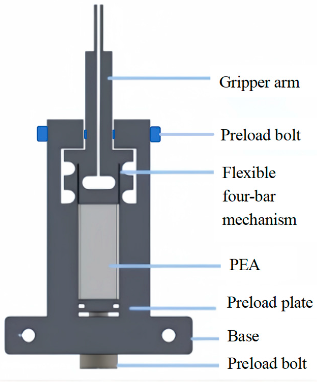
2.1. Structural Design of the Micro-Gripper

This paper proposes a design method for a compact yet large-stroke micro-gripper. The micro-gripper employs the link of a flexible four-bar mechanism as the amplification mechanism to achieve the output displacement at the gripper’s end. It consists of a main structure, piezoelectric ceramic actuators, and preloading bolts. The piezoelectric ceramic actuator is installed in the central groove of the main structure to provide driving force for the micro-gripper. A preloading bolt is mounted at the bottom of the gripper, and by pressing the preloading push plate, the piezoelectric ceramic actuator is brought into close contact with the micro-gripper. The gripping arms and the frame are directly connected via bolts and springs, causing the gripping arms to move inward in the initial state and thus close the gripping ends. Figure 1 shows a schematic diagram of the micro-gripper’s structure, with the main structure dimensions of 40 × 74.5 × 8 mm. Under the influence of voltage, the piezoelectric ceramic actuator elongates, thereby driving the flexible hinge part to open and close the gripping arms.

2.2. Design of the Flexure Four-Bar Mechanism

As shown in Figure 2a, the crank–slider mechanism is a typical four-bar mechanism. If the revolute joints at A, B, and C are replaced with flexure hinges, as illustrated in Figure 2b, and the linear actuation of the slider is achieved via a piezoelectric ceramic actuator, the rotation of crank AB and connecting link BC can be realized. Through a symmetrical configuration design, where two rigid bodies are connected to the two connecting links, the gripping arms of the micro-gripper are constituted, thereby completing the design of the gripper as depicted in Figure 1 and Figure 2c.
Based on the principles of flexure hinges, their stiffness exhibits significant anisotropy across different directions. When subjected to tension or compression, the axial stiffness substantially exceeds the radial bending stiffness. Consequently, for serially connected four-bar mechanisms, the arrangement of flexure hinges profoundly influences the mechanical behavior of the mechanism. Taking the canonical right-circular flexure hinge as an example, the configuration of flexure hinges in the four-bar mechanism is illustrated in Figure 2b. Flexure hinges H1 and H2 govern the rotational deflection of links l1 and l2. When the axial direction of flexure hinge H3 is aligned with the thrust direction of the piezoelectric ceramic actuator, the actuator’s thrust acts as an axial compressive load on H3. This alignment enables the flexure hinge to achieve maximum axial deformation, thereby yielding optimal energy efficiency.

3. Kinematic Analysis of the Flexure Four-Bar Mechanism

For the four-bar mechanism depicted in Figure 2a, a coordinate system is established to derive the projection equations of each vector:
l 1 cos φ 1 + l 2 cos φ 2 = l 3 cos φ 3 + l 4 l 1 sin φ 1 + l 2 sin φ 2 = l 3 sin φ 3
Differentiating the kinematic equations with respect to time yields the velocity equations (Equation (2)).
l 1 ω 1 sin φ 1 + l 2 ω 2 sin φ 2 = ϑ 3 cos φ 3 l 1 ω 1 cos φ 1 + l 2 ω 2 cos φ 2 = ϑ 3 sin φ 3
where ω 1 and ω 2 denote the rotational velocities of links AB and BC, respectively, while ϑ 3 represents the translational velocity of the slider. In flexure hinge transmission, ω 1 , ω 2 , and ω 3 can be regarded as the rotational displacements of flexure hinges A, B, and C, with δ being the translational displacement of the slider. Solving the governing equations yields the rotational displacements ω 1 , ω 2 , and   ω 3 for each hinge, as expressed in Equations (3) and (4).
ω 1 = ϑ 3 cos φ 3 l 2 ω 2 sin φ 2 l 1 sin φ 1
ω 2 = ϑ 3 sin φ 1 sin φ 3 cos φ 1 cos φ 3 l 2 cos φ 2 sin φ 1 cos φ 1 s i n φ 2
Under the structural configuration illustrated in Figure 2b, when the piezoelectric ceramic actuator drives the slider forward, ω 1 < 0 , ω 2 > 0 , and ω 3 > ω 2 , thus enabling the selection of link BC as the driving link to achieve motion amplification. To minimize the overall structural dimensions, the piezoelectric ceramic actuator is arranged to act along the Y-direction; that is, let φ 3 = 90 ° . The maximum rotation angle of link BC is then determined under the following condition, as defined in Equation (5).
0 φ 1 180 ° 90 ° φ 2 < 90 °
Under this condition, the rotational displacements ω 1 , ω 2 , and ω 3 of the respective hinges are given by Equations (6)–(8).
ω 1 = ϑ 3 sin φ 2 l 1 cos φ 2 sin φ 1 cos φ 1 s i n φ 2
ω 2 = ϑ 3 s i n φ 1 l 2 cos φ 2 sin φ 1 cos φ 1 s i n φ 2
ω 3 = ω 2 ω 1 = ϑ 3 l 2 sin φ 2 + l 1 s i n φ 1 l 1 l 2 cos φ 2 sin φ 1 cos φ 1 s i n φ 2
The position of point P along the X-axis is expressed by Equation (9).
X P = l 1 cos φ 1 + l 2 cos φ 2 + l 5 cos φ 5 + φ 2
The position variation of point P along the X-axis is given by Equation (10), where l 5   denotes the length of the gripping arm, and φ 5 represents the angle between the gripping arm and the extension line of the connecting link   l 2 .
X P = ω 1 l 1 sin φ 1 ω 2 l 2 cos φ 2 ω 2 l 5 sin φ 5 + φ 2 = ϑ 3 l 5 sin φ 1 sin φ 5 + φ 2 l 2 cos φ 2 sin φ 1 cos φ 1 s i n φ 2
The position of point P along the Y-axis is expressed by Equation (11).
Y P = l 1 sin φ 1 + l 2 sin φ 2 + l 5 sin φ 5 + φ 2
The position variation of point P along the Y-axis is defined by Equation (12).
Y P = ω 1 l 1 cos φ 1 + ω 2 l 2 cos φ 2 + ω 2 l 5 cos φ 5 + φ 2 = ϑ 3 1 + l 5 sin φ 1 cos φ 5 + φ 2 l 2 cos φ 2 sin φ 1 cos φ 1 s i n φ 2
The amplification factor δ X for the position of point P along the X-axis is calculated using Equation (13), while the amplification factor for its position along the Y-axis is given by Equation (14). Due to the negligible impact of the Y-axis position variation on the overall positional change, priority is given to analyzing the X-axis position variation of point P.
δ X = X P ϑ 3 = l 5 sin φ 1 sin φ 5 + φ 2 l 2 cos φ 2 sin φ 1 cos φ 1 s i n φ 2
δ Y = Y P ϑ 3 = 1 + l 5 sin φ 1 cos φ 5 + φ 2 l 2 cos φ 2 sin φ 1 cos φ 1 s i n φ 2
According to the above formulas, the relationship between the amplification ratio and key dimensions can be determined. To achieve a larger amplification ratio and compact overall dimensions, the value of l2 should be minimized as much as possible. Therefore, a single-edge straight circular flexure hinge is adopted. Considering the machining accuracy during wire cutting, the parameters l 2 , l 5 , φ 1 , φ 2 ,   and φ 5 in the preliminary design are set to 3.45 mm, 37.95 mm, 90 ° , 299.54 ° , and 147.53 ° , respectively; the amplification factor of the single-sided clamping arm is 22.28; and the amplification factor δ X of the clamp can be calculated as 44.56. The comparisons of properties were performed with the same type of compliant gripper mechanism described in [1,12,13], as shown in Table 1.

4. Finite Element Analysis

Through kinematic analysis, a computational model was established for the relationship between the input displacement of the piezoelectric ceramic actuator and the deformation displacement of the clamping arm, and the displacement amplification ratio formula of the micro-gripper was derived. To verify the accuracy of the above computational model, analysis was conducted using ANSYS simulation software.

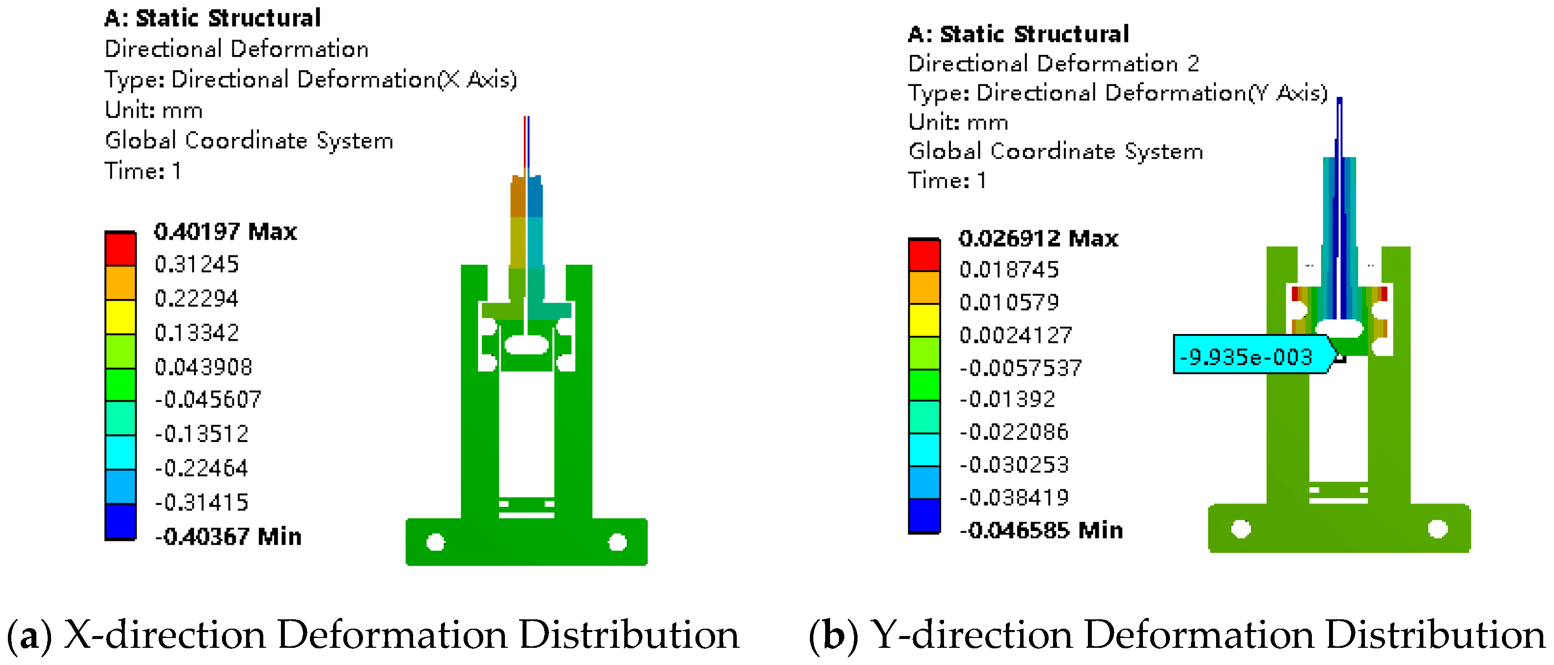
4.1. Analysis of Displacement Amplification Ratio

Through finite element analysis software ANSYS, the deformation and stress of the micro-gripper driven by a piezoelectric ceramic actuator were investigated. The micro-gripper material was selected as aluminum alloy 7075, which primarily undergoes elastic deformation. The relevant material properties were set as follows: elastic modulus of 72 GPa, Poisson’s ratio of 0.33, and density of 2810 kg/m3. To ensure the clamping arms remain in a closed position without applied voltage, spring components were incorporated in the simulation. By setting the spring stiffness and deformation, a preload force of 10 N was achieved, enabling the two tips of the gripper to close precisely. Finite element simulation results (Figure 3) show that the clamping arms deflect inward by approximately 401.97 μm, resulting in exact closure at the tips. The contact point with the PEA displaces downward in the Y-direction by 9.94 μm, with a maximum stress of 143.39 MPa, well below the yield strength (480 MPa) of the material.
When a driving force of 300 N is applied at the PEA position in the closed state, the deformation distributions in the X and Y directions are shown in Figure 4. The deformation in the X-direction changes from an initial value of 401.97 μm to 18.86 μm, allowing the calculation of a bilateral clamping distance of 766.22 μm for the gripping arm. Concurrently, the deformation at the PEA position in the Y-direction shifts from -9.94 μm to 8.87 μm, indicating that the PEA provides a driving displacement of 18.81 μm. This yields an amplification ratio of 40.73, which is consistent with the theoretical value.

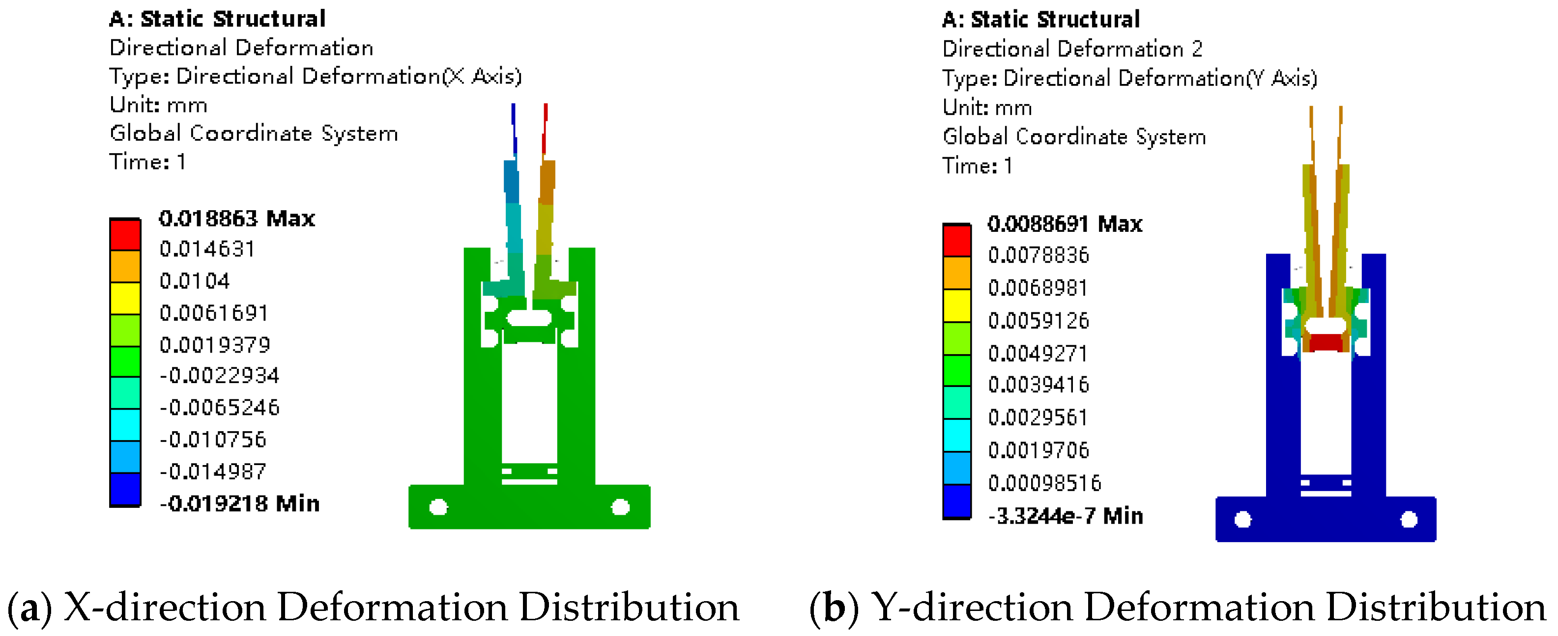
4.2. Clamping Force and Strain Analysis

During the micro-gripping process, the opening of the gripping arms is made larger than the thickness of the object to be gripped by increasing the PEA voltage. During the gripping process, the opening of the gripping arms is adjusted by lowering the PEA voltage, and the degree of opening determines the gripping force. Strain gauges are attached to the outer sides of the flexible gripping arms, as shown in Figure 5a, so that the gripping force can be analyzed by detecting the strain on the flexible arms. In the simulation process, the gripping distance and the strain value at the middle of the outer side of the gripping arm under different gripping forces are studied, and the results are shown in Figure 5b. As the gripping force increases from 0 to 3 N, the gripping distance increases from 0 to 280 μm, and the strain value rises from 200 με to 726 με. The obtained linear relationship between gripping force, gripping distance, and strain value can be used to assist in the control of force and displacement.

4.3. Modal Analysis

The modal simulation results are shown in Figure 6. The first six natural frequencies are 745.51 Hz, 811.35 Hz, 2552.4 Hz, 2563.2 Hz, 3506.4 Hz, and 4434.3 Hz, respectively. To avoid resonance, it is recommended to operate the micro-gripper below 450 Hz (60% of the first natural frequency); thus, this micro-gripper can achieve a relatively high working frequency.

5. Experimental Tests

This section experimentally validates the micro-gripper system, focusing on high-precision displacement control, adjustable gripping force, and seamless force–displacement switching. The platform integrates advanced motion control, sensing, and vibration isolation to ensure operational stability. The results confirm the system’s capability for precise micro-scale manipulation, demonstrating robust performance in multi-stage gripping tasks. The proposed control strategy enables accurate object handling, highlighting potential applications in micro-assembly and biomedical operations.

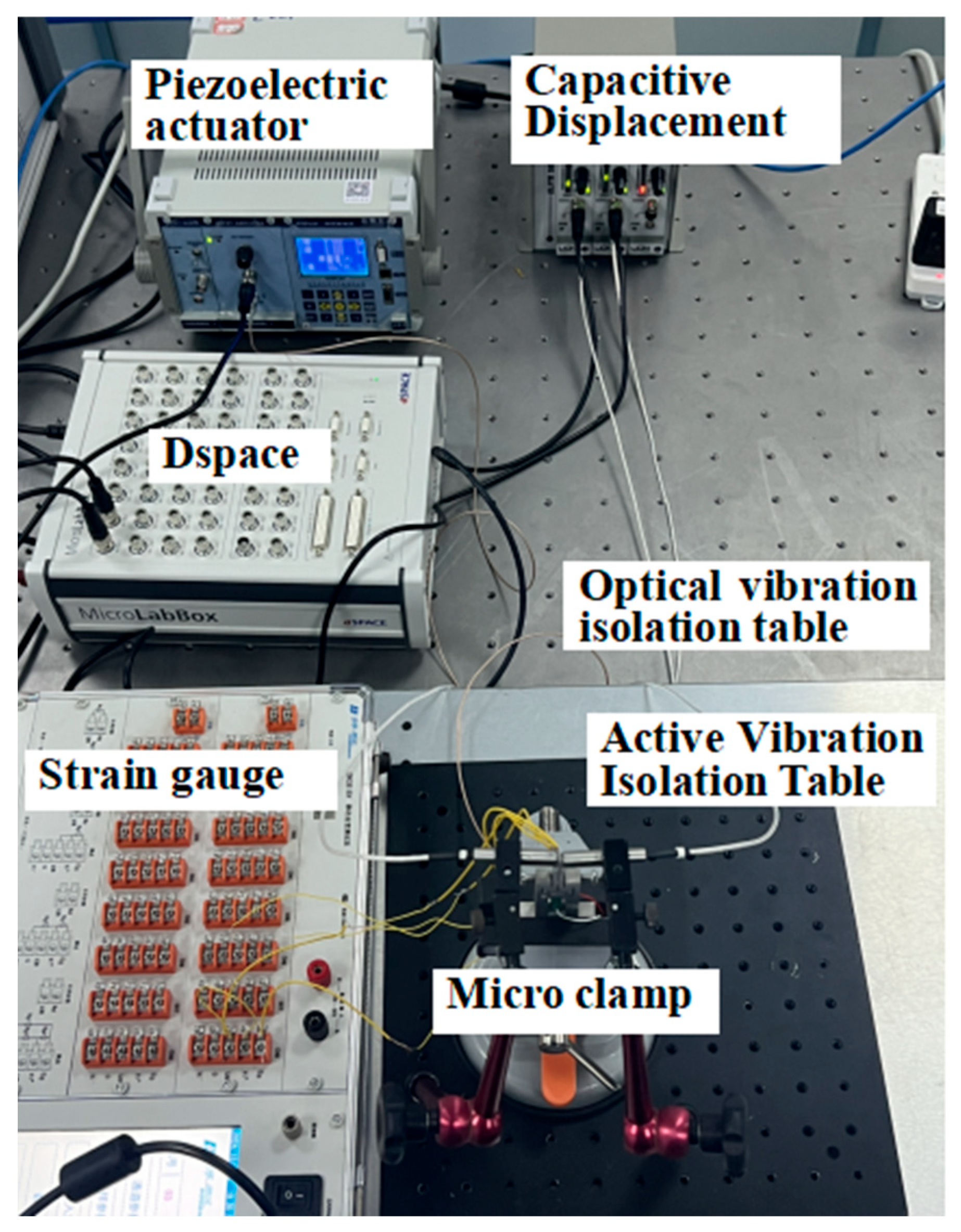
5.1. Building the Experimental Platform

The established experimental platform includes a Contoldesk computer, MicroLabBox, CoreMorrow ED01 voltage amplifier, capacitive displacement sensor (model), resistive strain gauge force sensor, active vibration isolation table, microscopic camera, micro-gripper, and CoreMorrow PSt150 piezoelectric actuator, as shown in Figure 7. Figure 5a depicts the sensors’ configuration employed in the force–displacement experiments.
To minimize the impact of vibrations on data accuracy, the active vibration isolation table is fixed onto an optical isolation platform, and the micro-gripper is clamped with a vise to enhance system stability and vibration isolation performance. The input signal is generated and amplified by the Dspace system to drive the piezoelectric actuator, which outputs displacement and force. The maximum output displacement of the actuator is 21 μm, and the maximum thrust is 1600 N, meeting the experimental requirements. The capacitive displacement sensor and strain gauge sensor monitor the displacement and gripping force of the gripper, respectively. All sensor data are transmitted to the Dspace platform via the data acquisition system for processing and analysis.

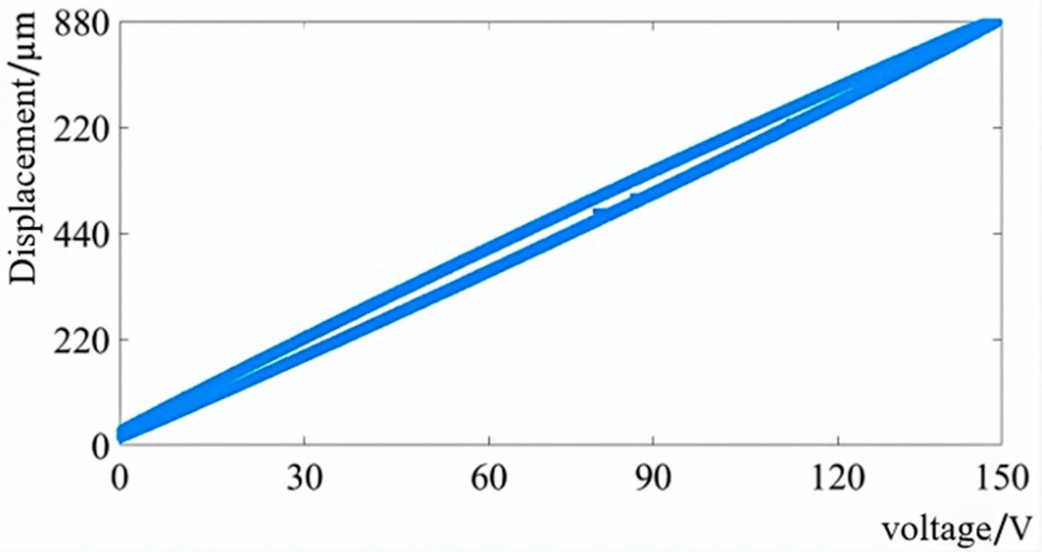
5.2. Displacement Characteristic Experiment

As the driving voltage applied to the piezoelectric actuator increases, the relationship between the gripping stroke and the voltage can be obtained, as shown in Figure 8. When the maximum voltage is applied, the gripping distance at the front end of the micro-gripper is 880 μm. The amplification ratio is defined as the ratio of the gripping distance at the front end of the micro-gripper to the applied displacement, which in this case is 41.9. The observed hysteresis behavior in the plot contributes to displacement control inaccuracies, though these nonlinear effects are conducive to compensation via implemented closed-loop control methodologies.
In the experiment, the amplitude of the input step signal was gradually increased and the signal height was progressively reduced until the minimum distinguishable displacement of the system was identified. As shown in Figure 9, the error between the actual displacement and the desired displacement of the micro-gripper was successfully controlled within 50 nm, indicating that it can effectively control displacement under high-precision requirements.

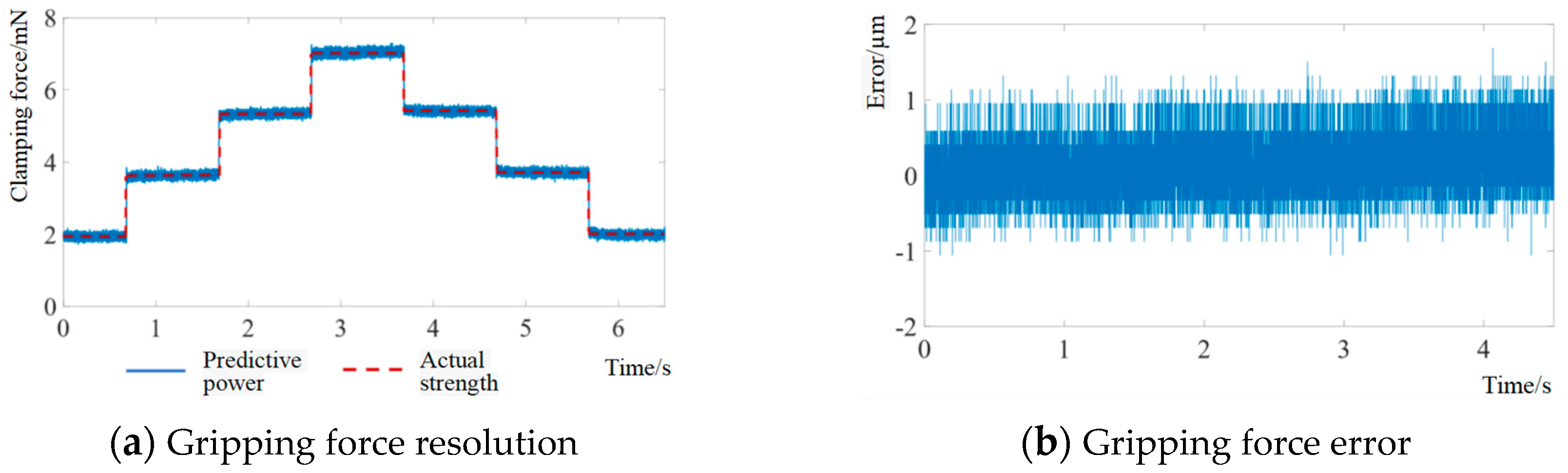
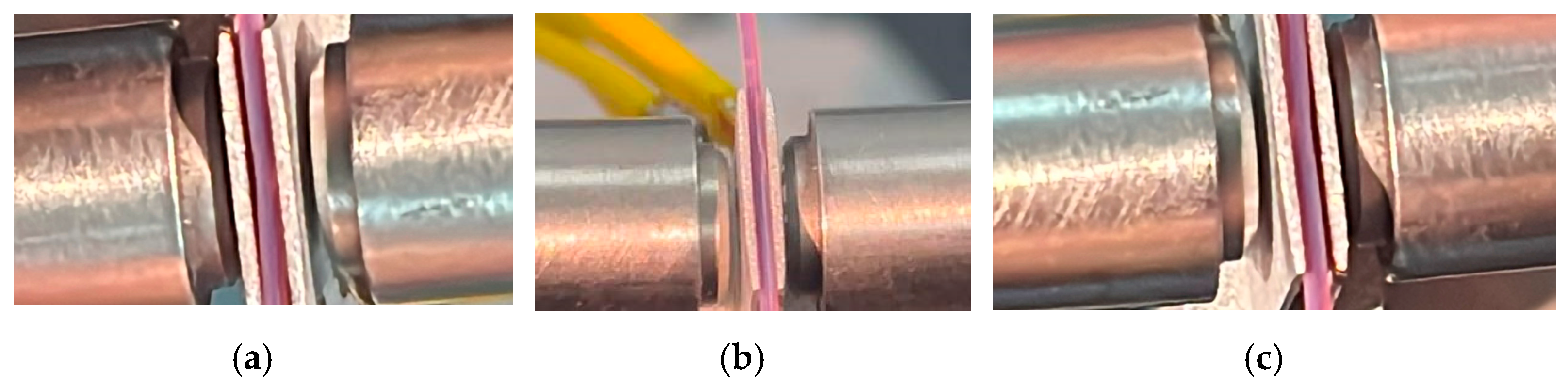
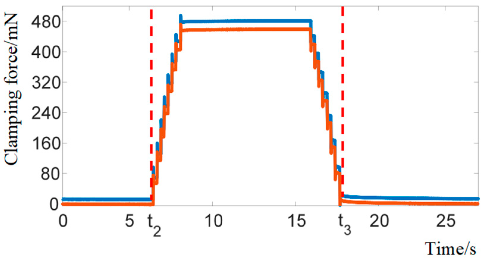
5.3. Gripping Force Test Experiment

In the gripping force test experiment, the sensor arrangement shown in Figure 5a was used. Two capacitive displacement sensors measured the gripping distance between the arms, and a calibrated strain gauge displacement sensor was used as the feedback element for the gripping force. In the experiment, a metal wire with a diameter of 400 μm was gripped and released by controlling the displacement of the micro-gripper.
During the experiment, the gripping arms were first fully opened by applying the maximum voltage of 150 V. After placing the plastic tube between the gripping arms, the PEA voltage was reduced to 0 V, allowing the preloaded spring to clamp the plastic tube. The PEA voltage was then increased from 0 to 75 V in 5 V steps. As shown in the experimental results in Figure 10a, although the theoretical gripping distance based on the PEA output displacement continuously increased, the gripping distance measured by the capacitive displacement sensor remained unchanged. Meanwhile, the gripping force measured by the strain sensor continuously decreased, as shown in Figure 10b, dropping to zero when the voltage reached 75 V. This indicates that during the gripping process, the plastic tube was not compressed or deformed, but the continuous decrease in strain at the end of the flexible beam of the gripping arm shows that the gripping force was decreasing. Thus, the gripping force can be adjusted by controlling the PEA voltage.
By continuously reducing the step value of the PEA input voltage, the resolution of the micro-gripper’s gripping force was observed. The measurement results are shown in Figure 11a, where the red dashed line represents the desired gripping force input signal and the blue solid line represents the actual gripping force output signal. Figure 11b shows the error curve between the desired and actual gripping forces, with the error controlled within 2 mN. This duration constitutes a representative operational window for micro-manipulation tasks, while the 2 mN force regulation accuracy proves sufficient for practical applications.

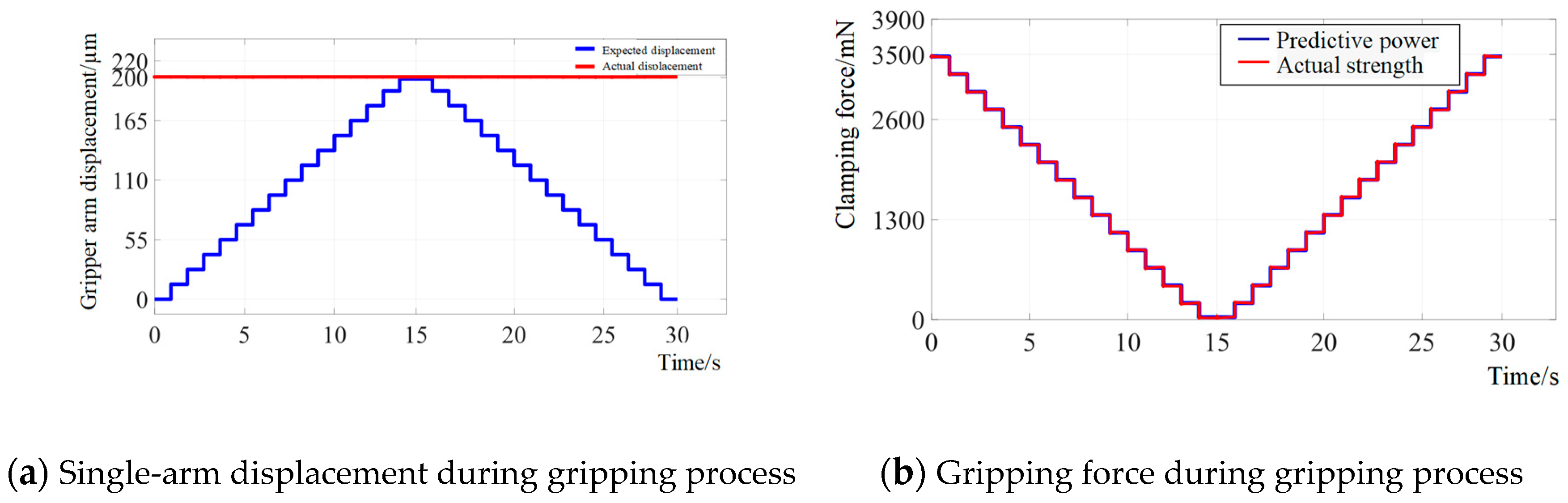
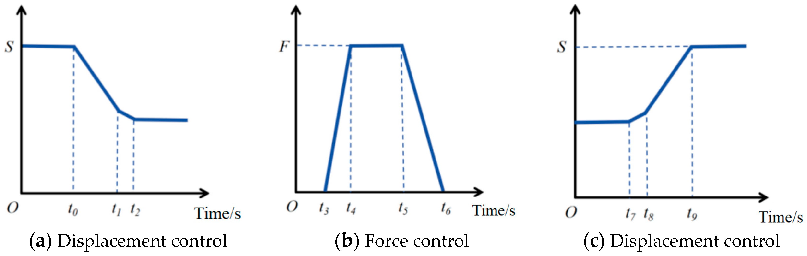
5.4. Gripping Force–Displacement Switching Control

To test the gripping force–displacement switching control function, a silicone tube with a diameter of 365 μm was used as the gripping object. During the gripping process, the switching control between force and displacement is shown in Figure 12 and Figure 13. In Figure 12a, t0 to t1 represents the rapid approach under displacement control, and t1 to t2 represents the gentle approach under compliant control. In Figure 12b, t3 to t6 represents force control. In Figure 12c, t7 to t8 represents gentle release under compliant control, and t8 to t9 represents rapid release under displacement control.
Figure 14 and Figure 15 show the changes in the motion state of the gripper at different time periods. From 0 to t1, a single arm of the gripper approaches the target object at a speed of 30 μm/s, starting from 332 μm, to prepare for subsequent fine control. From t1 to t2, the gripper enters compliant control mode, slowing down to 2 μm/s to ensure precise contact. From t2 to t3, the gripper switches to force control mode, adjusting the gripping force to 480 mN and maintaining it for 15 s to ensure stability. From t3 to t4, the gripper enters a critical state, holding for 2 s to avoid instability, and then returns to compliant control mode, withdrawing at a reduced speed. After t4, the gripper resumes rapid position control mode and quickly returns to its initial position. Throughout the entire process, precise switching between control modes ensures the accuracy and stability of the gripping operation.
From the above experiments, it can be seen that seamless switching between displacement control and gripping force control was achieved during the gripping process. The motion control strategy of the gripper ensures precise contact with the target object and stable gripping. Through multi-stage fine control, the gripper can effectively accomplish precision operation tasks. Micro/nano-scale manipulation operations are conventionally executed in temperature-controlled environments, rendering thermal effects on positioning accuracy negligible. The low operational frequencies characteristic of such processes, combined with the system’s closed-loop control architecture, ensure minimal thermal influence from the micro-gripping mechanism.

6. Conclusions

In response to the demand for submillimeter gripping capability in micro-grippers, this paper designs an amplification mechanism based on a compliant four-bar linkage, achieving a large gripping stroke in the millimeter range. Through structural design and theoretical analysis, it is confirmed that the compliant four-bar mechanism has great potential for ultra-high amplification ratios, providing a theoretical foundation for the design of micro-grippers. Kinematic and mechanical simulation analyses conducted using ANSYS further validate the correctness of the theoretical model. Experimental results show that the displacement amplification ratio of the micro-gripper is as high as 40, the displacement resolution reaches 50 nm, and the gripping range is between 0 and 880 μm. In addition, force and displacement fusion control is achieved through capacitive displacement sensors and strain sensors. This submillimeter gripper enables force–displacement switching control for precision applications like micro-assembly (MEMS/optics) and biomedical manipulation (cell surgery), offering cost advantages through simpler mechatronic integration and standardized actuators.

Author Contributions

Conceptualization, L.C. and Y.C.; methodology, X.D. and H.Z.; validation, H.Z. and X.D.; writing—L.C., H.Z., X.D., and Y.C. All authors have read and agreed to the published version of the manuscript.

Funding

This research was funded by the Tianjin Metrology Technology Project (2024TJMT048, 2025TJMT008), Tianjin Education Committee Scientific Research Program Project (2023KJ189), and Tianjin Science and Technology Program Project (24PTLYHZ00030).

Data Availability Statement

Data available upon the requests from the authors.

Conflicts of Interest

The authors declare no conflicts of interest. The founding sponsors had no role in the design of the study; in the collection, analyses, or interpretation of data; in the writing of the manuscript; or in the decision to publish the results.

References

  1. Wang, F.; Liang, C.; Tian, Y.; Zhao, X.; Zhang, D. Design and control of a compliant microgripper with a large amplification ratio for high-speed micro manipulation. IEEE/ASME Trans. Mechatron. 2016, 21, 1262–1271. [Google Scholar] [CrossRef]
  2. Lin, M.; Meng, G.; Sheng, Y.; Li, W.; Cao, Y. Analysis and Optimization of a Microgripper with Flexible Structure. J. Donghua Univ. (Nat. Sci.) 2021, 47, 96–104. [Google Scholar] [CrossRef]
  3. Shi, C.; Dong, X.; Yang, Z. A microgripper with a large magnification ratio and high structural stiffness based on a flexure-enabled mechanism. IEEE/ASME Trans. Mechatron. 2021, 26, 3076–3086. [Google Scholar] [CrossRef]
  4. Lyu, Z.; Xu, Q. Design and Testing of a New Piezoelectric-Actuated Symmetric Compliant Microgripper. Actuators 2022, 11, 77. [Google Scholar] [CrossRef]
  5. Qian, J.; Yan, P.; Liu, P. Position/force modeling and analysis of a piezo-driven compliant micro-gripper considering the dynamic impacts of gripping objects. Smart Mater. Struct. 2021, 30, 075036. [Google Scholar] [CrossRef]
  6. Song, S.; Yang, Y.; Wu, G.; Zhang, S.; Wei, Y. Design and Analysis of a Piezoelectric Compliant XY Microgripper. J. Vib. Shock 2022, 41, 154–161. [Google Scholar] [CrossRef]
  7. Chen, X.; Xie, Z.; Tai, K.; Tan, H. Design of low parasitic motion microgripper based on symmetrical parallelogram mechanism. Sens. Actuators A 2024, 367, 115072. [Google Scholar] [CrossRef]
  8. Wu, Z.; Wang, Y.; Chen, M.; Ding, B. Design, analysis, and experimental investigations of an asymmetrical under-actuated micro-gripper. J. Intell. Mater. Syst. Struct. 2024, 35, 960–970. [Google Scholar] [CrossRef]
  9. Xu, D.; Yang, F.; Yu, S.; Xu, C.; Liu, X.; Zhao, Z.; Zhang, X.; Li, S.; Yang, H.; Lu, Q. A three-stage amplification piezoelectric-actuated micro-gripper with adjustable output displacement: Design, modeling, and experimental evaluation. Smart Mater. Struct. 2023, 32, 095033. [Google Scholar] [CrossRef]
  10. Guo, Z.; Ma, H.; Li, Q.; Li, Y.; Liu, Z.; Song, Q. Design and analysis of a compliant microgripper with a large amplification ratio. Microcyst. Technol. 2023, 29, 1333–1341. [Google Scholar] [CrossRef]
  11. Ni, L.; Chen, G.; Hong, K.; Wang, G. Design and development of a compliant piezoelectric microgripper based on three-stage amplification. Microsyst. Technol. 2023, 29, 939–952. [Google Scholar] [CrossRef]
  12. Chen, F.; Du, Z.J.; Yang, M.; Gao, F.; Dong, W.; Zhang, D. Design and Analysis of a Three-dimensional Bridge-type Mechanism based on the Stiffness Distribution. Precis. Eng. 2018, 51, 48–58. [Google Scholar] [CrossRef]
  13. Liang, C.; Wang, F.; Shi, B.; Huo, Z.; Zhou, K.; Tian, Y.; Zhang, D. Design and control of a novel asymmetrical piezoelectric actuated microgripper for micromanipulation. Sens. Actuators A 2018, 269, 227–237. [Google Scholar] [CrossRef]
Figure 1. Structural diagram of micro-gripper.
Actuators 14 00338 g001
Figure 2. Schematics of the four-bar mechanism. (a) Crank–Slider Mechanism. (b) Four-Bar Mechanism with Flexure Hinges. (c) Simplified Diagram of the Unilateral Flexure Four-Bar Gripping Arm.
Actuators 14 00338 g002
Figure 3. Deformation distribution at closed position under spring action.
Actuators 14 00338 g003
Figure 4. Deformation distribution under 300 N of driving force.
Actuators 14 00338 g004
Figure 5. Linear relationship between gripping force, gripping distance, and strain. (a) Arrangement of sensors for force–displacement experiment. (b) Relationship between gripping force, gripping distance, and strain.
Actuators 14 00338 g005
Figure 6. Modal analysis of the micro-gripper.
Actuators 14 00338 g006
Figure 7. Experimental setup diagram.
Actuators 14 00338 g007
Figure 8. Experimental results of the amplification ratio of the micro-gripper.
Actuators 14 00338 g008
Figure 9. Displacement resolution test of micro-gripper.
Actuators 14 00338 g009
Figure 10. Changes in single-arm displacement and gripping force during the gripping process.
Actuators 14 00338 g010
Figure 11. Gripping force resolution test of micro-gripper.
Actuators 14 00338 g011
Figure 12. Switching control of force and displacement during micro-wire gripping process.
Actuators 14 00338 g012
Figure 13. Experimental images of gripping a 365 μm fine wire. (a) Gripper arms approaching the object to be gripped. (b) Gripper arms gripping the object. (c) Gripper arms releasing the object.
Actuators 14 00338 g013
Figure 14. Variation in gripping end distance.
Actuators 14 00338 g014
Figure 15. Variation in gripping force.
Actuators 14 00338 g015
Table 1. Performance comparisons.
ReferenceMechanical Size/mmAmplification MechanismAmplification Ratio
[1]42 × 25Three-stage bridge–lever-type amplifier22.8
[12]60 × 40Scott–Russell mechanism and lever-type mechanism16
[13]55 × 22Bridge–lever amplifier13.94
This work75 × 40Flexible four-bar linkage mechanism44.56
Disclaimer/Publisher’s Note: The statements, opinions and data contained in all publications are solely those of the individual author(s) and contributor(s) and not of MDPI and/or the editor(s). MDPI and/or the editor(s) disclaim responsibility for any injury to people or property resulting from any ideas, methods, instructions or products referred to in the content.

