Abstract
Stroke is one of the leading causes of long-term disability worldwide, often resulting in motor impairments that limit the ability to perform daily activities independently. Conventional rehabilitation exoskeletons, while effective, are typically rigid, bulky, and expensive, limiting their usability outside of clinical settings. In response to these challenges, this work presents the development and validation of a novel soft exosuit designed for elbow flexion rehabilitation, incorporating a multi-wire Shape Memory Alloy (SMA) actuator capable of both position and force control. The proposed system features a lightweight and ergonomic textile-based design, optimized for user comfort, ease of use, and low manufacturing cost. A sequential activation strategy was implemented to improve the dynamic response of the actuator, particularly during the cooling phase, which is typically a major limitation in SMA-based systems. The performance of the multi-bundle actuator was compared with a single-bundle configuration, demonstrating superior trajectory tracking and reduced thermal accumulation. Surface electromyography tests confirmed a decrease in muscular effort during assisted flexion, validating the device’s assistive capabilities. With a total weight of 0.6 kg and a fabrication cost under EUR 500, the proposed exosuit offers a promising solution for accessible and effective home-based rehabilitation.
1. Introduction
According to the World Health Organization (WHO), approximately 15 million people suffer a stroke each year worldwide. Of these cases, it is estimated that 5 million are left with permanent disabilities, representing a significant burden for both families and healthcare systems [1]. Similarly, the World Stroke Organization reports that more than 12 million people will experience their first stroke episode this year [2]. These data highlight the magnitude of the problem and underscore the urgent need to implement effective strategies for stroke prevention, early diagnosis, and treatment on a global scale.
When such neurological conditions occur, the affected individual often experiences impairments in motor and sensory functions, vision, or language, which significantly impact their ability to perform daily activities [3]. Depending on the severity of the impairment, the person may become dependent on assistance from others.
From a diagnostic and therapeutic standpoint, rehabilitation exoskeletons have made substantial progress in recent years. These devices enable repetitive, precise, and intensive rehabilitation, providing valuable support to therapists by reducing their workload and, concurrently, lowering healthcare-related costs [4]. Nevertheless, exoskeletons still face several technical challenges, such as power-to-weight ratio, safety and control, portability and ease of use, comfort and adaptability, cost, and cognitive synchronization with the patient [5]. One potential approach to addressing these challenges is to focus on the development of soft exoskeletons, exosuit-type devices. These systems better adapt to the patient’s biomechanics, minimizing movement restrictions and improving overall usability.
Focusing on the upper limb, numerous exosuit-type exoskeletons have been proposed in recent years. In [6], a textile-based soft elbow exosuit is presented, incorporating an adaptive mechanism and composite bellows designed to reduce mechanical resistance and increase output torque during elbow flexion. Experimental validation demonstrated a 78.6% reduction in mechanical resistance and a 207% increase in output torque compared to conventional designs, enabling full range of motion (0°–130°) and effective weight-lifting assistance with reduced muscle activation. Nevertheless, being a pneumatic actuator, the relationship between input pressure and output torque is inherently nonlinear, which complicates accurate control and system modeling.
An exosuit actuated by pneumatic artificial muscles is also presented in [7] inspired by the anatomy of the brachioradialis muscle and employing a pennate architecture. The device achieves a maximum elbow torque of 9.15 Nm, covering a range of motion from 0° to 120°. However, it relies on an external pneumatic pressure source and features a control system based on fixed valves and pressure levels, which adds complexity to its operation.
In [8], the anchor point configuration for generating motion in a soft exosuit actuated by a cable-driven mechanism was studied. This was validated using a test bench consisting of two metal bars simulating the upper arm, forearm, and elbow joint. The results demonstrate that increasing the distance between the cable guide and the elbow’s center of rotation improves the efficiency of the exosuit by reducing the required muscle activation.
A modular exoskeleton for upper limb rehabilitation, combining rigid structures with soft reconfigurable joints based on pneumatic chambers, was presented in [9]. The system allows for adjustment of the range of motion and stiffness of each joint, and was validated through tests with healthy users, demonstrating precise control and adaptability to different movement trajectories. Although each soft exoskeleton module is lightweight, the complete system—including pumps, valves, and controllers—is bulky and uncomfortable for prolonged use outside of the laboratory.
A textile-based soft exosuit for elbow rehabilitation was also developed, featuring a lightweight and customizable modular pneumatic actuator [10]. The design achieves an output torque of 7.18 Nm and a range of motion greater than 100°, validated through both static and dynamic tests. The system aims to enhance comfort, safety, and effectiveness in assisting elbow flexion movements in stroke patients.
Although most devices use cable-driven actuators or pneumatic artificial muscles, soft exoskeletons actuated by Shape Memory Alloys (SMA) have also been developed [11,12]. One example is a soft elbow exoskeleton powered by SMA springs [13]. The device is capable of generating a torque of up to 0.063 Nm and achieving a range of motion of up to 60°. Another example is a soft exoskeleton actuated by an SMA coil spring bundle, designed to assist elbow flexion and forearm pronation–supination. The device achieves a maximum elbow joint torque of 1.96 Nm [14].
The main limitations of these devices—such as volume, weight, or, in the case of SMA-actuated systems, reduced torque and speed—are directly related to the type of actuator used. For this reason, this work presents a novel multi-bundle SMA actuator for rehabilitation devices, featuring both position and force control. Additionally, the proposed actuator is integrated into the design of a soft exosuit for elbow joint rehabilitation, demonstrating its feasibility. The proposed design overcomes the current limitations of similar devices, achieving a maximum torque of 5.23 Nm and an elbow flexion range of motion between 0 and 120 degrees.
This article is structured as follows. Section 2 presents the materials and methods used in the study, including the biomechanical analysis of the elbow joint, the design of the multi-wire SMA actuator, the electronic components, the exosuit construction, and the control strategy. Section 3 describes the experimental setup and provides the results obtained both on the test bench and with user trials. In Section 4, the results are discussed in terms of actuator performance, user assistance, and design limitations. Finally, Section 5 outlines the main conclusions and proposes future lines of research.
2. Materials and Methods
This section details the biomechanical aspects, the design of both the actuator and the exosuit, the electronics, sensors, and the control strategy implemented to achieve precise tracking of the exosuit’s position and force.
2.1. Biomechanics
The elbow is the joint that connects the humerus (upper arm) with the radius and ulna (forearm), enabling the hand to move toward and away from the body. This joint exhibits two degrees of freedom (2-DOF): one for flexion–extension and another for pronation–supination. The angular range of motion for flexion–extension typically spans from 0° to 150°, although the functional range required for performing activities of daily living (ADLs) is generally between 30° and 120°. Regarding forearm rotation, average values are approximately 71° for pronation and 81° for supination. In the context of ADLs, however, the functional range is around 50° for both pronation and supination [15]. According to the study presented in [16], for an individual weighing 80 Kg and 1.8 m tall performing elbow flexion–extension at a frequency of 0.25 Hz, the required peak torque is approximately 3.5 Nm. In this case, it is assumed that the entire torque required to move the joint is provided by the exoskeleton, with no contribution from the patient during the movement. The proposed design should exceed this torque in order to be capable of moving the patient’s forearm when it is fully impaired.
2.2. Multi-Bundle SMA Actuator
An SMA is a material capable of returning to its original (trained) shape after deformation when heated above its transformation temperature. This behavior results from a reversible phase transition between martensite (at low temperatures) and austenite (at high temperatures). The most commonly used SMA for actuation is Nitinol, a nickel–titanium (Ni-Ti) alloy. Owing to its superelastic properties, Nitinol can withstand millions of deformation–recovery cycles, provided that the strains remain within its recovery range. In this work, the Joule effect is employed to heat the material, converting electrical energy into thermal energy, which is then transformed into mechanical work [17]. This type of actuator has been previously employed in a range of applications, including prosthetic hands [18,19], exoskeletons [20,21], aerospace systems [22], and robotics [23]. In the case of the proposed actuator, no forced cooling or locking mechanisms will be used, in order to maintain the simplicity of both the actuator and the overall system.
The actuator proposed in this work builds upon the previous study presented in [24], which demonstrated the superiority of a multi-wire actuator with a novel strategy of control activation algorithm compared to single-wire and conventional SMA bundle actuators. This multi-wire configuration exhibited faster recovery to the initial position (in the cooling stage) due to the use of an activation strategy in which three independent actuators are alternately and independently activated. In this work, the proposed actuator consists of three bundled units, each comprising three SMA wires arranged in a parallel configuration (see Figure 1).
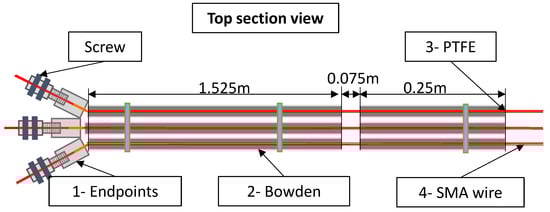
Figure 1.
Multi-bundle SMA actuator. Components: 1—Endpoint terminal connections. 2—Bowden cables (one per bundle). 3—PTFE tubes (one per bundle for electrical insulation). 4—SMA wires (three wires per bundle arranged in parallel).
In Figure 1, the SMA wires are shown in red, and each wire has a length of 1.85 m. Inside each Bowden sheath (gray), there is a PTFE tube (yellow), which contains three SMA wires arranged in parallel. The highlighted 0.075 m section represents the free zone (where both the Bowden and PTFE tubes are interrupted), allowing the SMA to contract. The final actuator consists of three parallel Bowden cables, each with a diameter of 6 mm. Each cable includes its own PTFE tube and three SMA wires.
Each bundle unit consists of two terminal connectors that crimp the three SMA wires and provide electrical connections, one metallic Bowden cable that transmits the force to the target point, a PTFE tube that electrically insulates the Bowden cable from the SMA wires, and three SMA wires with a diameter of 0.51 mm and an activation temperature of 90 °C, supplied by Dynalloy Inc. Each SMA wire present a pull force of 34.91 N which resulting a pull actuator force (each bundle) of 104.73 N. The pull force generated during heating is calculated based on a stress of 25,000 psi (172 MPa), as specified in the Dynalloy Inc. datasheet [25].
To properly characterize the required performance of the SMA actuator, it is essential to consider the proportion of forearm and hand weight relative to total body mass. According to the literature, the combined mass of the forearm and hand represents approximately 3% of total body weight in men and 2.8% in women [26]. In our case, the experiments were conducted on a male subject with a body weight of 80 kg, resulting in an estimated combined forearm and hand weight of approximately 3.2 kg. Considering that the actuator applies force at a distance of 0.05 m from the elbow joint, and accounting for angle-dependent decomposition of force, the maximum required actuator force is estimated to be around 100 N, excluding the singular configuration at an elbow joint angle of 0°.
The total length of the actuator is 1.85 m, which, according to the Dynalloy datasheet, can produce a displacement of 0.074 m. In the proposed actuator design, this displacement is transmitted to the elbow joint, where an intentional interruption of 0.075 m (Figure 1) in the Bowden cable and PTFE tube allows the motion to generate elbow rotation.
2.3. Electronics and Testbench
The control electronics consist of an STM32F4 microcontroller [27], responsible for acquiring signals from various sensors, executing control algorithms, and communicating with the user interface. To activate the SMA fibers, a Pulse-Width Modulation (PWM) signal generated by the control algorithm is used to drive the power electronics through an MOSFET [28] capable of handling currents of up to 20 A.
The elbow angular position was measured using an AS5045 rotary position sensor [29] manufactured by ams AG. The sensor was mounted on a 3D-printed joint composed of two segments, which can be externally attached to the proposed exosuit at the elbow joint using Velcro.
Additionally, for force measurement, an FSR 404 sensor from Interlink [30] was used. The sensor was placed between the actuator endpoints and the Bowden cable, sandwiched between two metal plates with rubber layers on each side and the sensor in the middle. The SMA wires passed through this assembly in such a way that, when activated, the pressure between the actuator endpoints and the Bowden cable could be measured.
The control algorithms were initially tested on test benches that allowed both linear and rotational displacement configurations, as presented in a previous work [24]. These test benches were equipped with position and current sensors. The force sensor used in the test bench was the same as the one implemented in the exosuit. The rotary test bench consists of two aluminum bars representing the upper arm and forearm, connected by an intermediate rotational axis that allows flexion–extension (1 DOF), abstractly simulating the elbow joint with a single degree of freedom. The forearm section of the test bench includes multiple holes for attaching weights, enabling the simulation of different torques at the joint. Additionally, the elbow joint is equipped with a pulley to which the SMA actuators are connected. The schematic of the rotary test bench and the actual test setup can be seen in Figure 2.
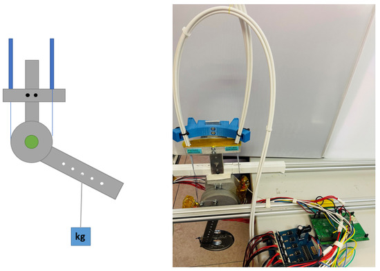
Figure 2.
Rotary test bench. (Left): Schematic representation of the test bench, where the actuators are shown in blue, and the segments and joint of the test bench are shown in gray. (Right): Image of the actual test bench setup along with its electronic components.
Additionally, to acquire the electromyography (sEMG) signal, a Quattro sensor with four channels from the company Bioelettronica [31] was used. This sensor was connected directly to the microcontroller via an analog port for sEMG acquisition. Although the sensor supports a sampling frequency of 1024 Hz, the data were acquired at 500 Hz. These data will be used for muscle activity evaluation during the exosuit test.
2.4. Exosuit
The exosuit design considered several key aspects: a good fit to the human body, ease of donning and doffing, user comfort, ease of cleaning, and the use of readily available materials. Figure 3 shows the proposed exosuit design. It is based on a garment tailored for a unisex subject, along with a neoprene glove. The actuators were fixed (sewn) at specific key points, including the arm region approximately 0.05 m from the elbow joint, as well as on the forearm and the dorsal part of the glove. These key attachment points were reinforced with adjustable fastening straps, which provide the mechanical link between the garment and the actuators. These straps play a critical role in the exosuit design, serving as the interface with the human body through which the actuators transmit force to the forearm and upper arm segments. The farther the anchor point is from the elbow, the less force is required from the actuator to move the joint, at the cost of a greater displacement. In this design, since the SMA actuator provides a limited stroke, the anchor distance was selected so that a maximum displacement of 0.074 m results in a 120-degree rotation. Adjustable straps allow for slight repositioning of these anchor points. As a result of the placement of these key attachment points, activation of the actuators (contraction) mobilized the user’s elbow joint, producing a flexion movement.
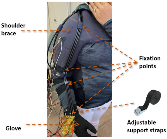
Figure 3.
Proposed exosuit design integrating the multi-bundle SMA actuator.
Additionally, to enhance the robustness of the system during activation, the shoulder area was reinforced with an adjustable shoulder brace from the company Orliman [32], made of neoprene.
To insulate the actuator endpoints, Kapton tape was used due to its high temperature resistance of up to 350 °C. This tape was applied at both ends of the actuator.
The estimated weight of the exosuit is approximately 0.6 kg, excluding the electronics and power source. The total weight, including the electronics, is approximately 1.55 kg. Of this, 0.08 kg corresponds to the STM32F4 microcontroller, 0.04 kg to the power stage, and 0.83 kg to the power supply (PLUS CP20.241) [33]. This low weight improves user comfort and facilitates the medical rehabilitation process, while also enhancing overall device acceptance.
2.5. Control Strategy
Due to the nonlinear characteristics of SMA wires—including hysteresis—the proposed actuator exhibits nonlinear behavior, which necessitates the design of nonlinear control loops. The behavior of SMA actuators is governed by thermomechanical phenomena, making their response difficult to predict. While several studies have attempted to model the behavior of SMA wires [34,35,36], these models are highly dependent on specific wire characteristics and environmental conditions. In more complex actuator designs, such as the one proposed here—where multiple wires are arranged in parallel, interacting with PTFE tubes, and influenced by terminal constraints—the modeling becomes significantly more complex and challenging to implement. For this reason, controller parameter tuning was carried out on the test bench using the trial-and-error method.
The primary goal of the control strategy is to enhance the dynamic performance of the actuator, particularly in tracking sinusoidal reference signals. To address this issue, a Bilinear Proportional–Integral–Derivative (BPID) controller illustrated in Figure 4 was implemented. This control approach is supported by findings in the literature [24,37] and was selected as a compromise between performance and robustness.
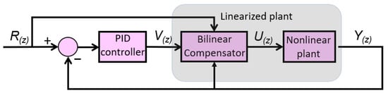
Figure 4.
BPID controller for the proposed actuator.
Figure 4 illustrates the control scheme proposed for the actuator, which consists of a bundle of three SMA wires. This control architecture enables both position and force control, with closed-loop feedback based on either the elbow joint angular position or the actuator force signal. In the diagram, represents the reference input, which can be either position or force. The signal corresponds to the output of the Proportional–Integral–Derivative (PID) controller, while denotes the control signal modified by the bilinear term. Finally, represents the measured output, corresponding either to the elbow joint position or the force measured by the force sensor.
The discrete equation (with a sample time of 0.002 s) (Equation (1)) of the bilinear compensator is as follows:
where is the bilinear gain. The PID controller is defined by Equation (2):
where is the proportional gain, is the derivative gain, is the integral gain, and is the error.
In the case of the multi-bundle actuator, each bundle consists of three wires, and each bundle must be activated sequentially. When one bundle is active, the other two remain at rest. In the next cycle, the second bundle is activated while the remaining two are inactive, and so on. This activation sequence selects the appropriate wire bundle based on an internal counter and the reference signal, sending a PWM signal to the active actuator while setting the PWM signals of the other two to zero. Based on this strategy, the control scheme was modified by adding a new block corresponding to the activation sequence selector (Figure 5). The advantage of using a multi-wire actuator with sequential activation over a single-wire actuator was demonstrated by the research group in a previous publication [24]. In this work, the multi-wire actuator is replaced by a multi-bundle actuator, which, due to the presence of multiple wires arranged in parallel within each bundle, increases the control complexity.
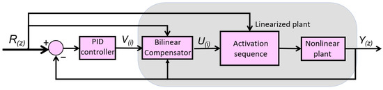
Figure 5.
BPID controller for the multiwire proposed actuator.
The BPID controller was tuned for the two proposed control strategies: position control and force control of the actuator. In both cases, the trial-and-error method was used, and the resulting controller gains are presented in Table 1.

Table 1.
BPID controller gains.
3. Results
Prior to integration into the exosuit, the control algorithms were tuned and validated using the testbench. Two different test benches were used for this purpose: one that allows linear displacement, and another that simulates a joint, enabling the evaluation of various actuator configurations, including an antagonistic setup. In this study, the experiments were limited to the agonist configuration, as the exosuit is actuated only for the flexion movement.
3.1. Testbench Results
The actuator (one bundle) was mounted on the linear test bench by fixing one end of the SMA actuator to the movable part of the bench, where displacement can be measured, and attaching the other end to the Bowden cable, replicating the same attachment method used in the exosuit. With this configuration, different step inputs were applied to observe the actuator’s response and to adjust the controller gains accordingly. The final response of the actuator can be observed in Figure 6, where it tracks a series of random step inputs.
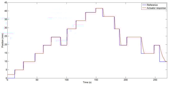
Figure 6.
Actuator response following step inputs.
As shown in Figure 6, the largest position error occurs during the actuator’s cooling phase, where the response depends on passive heat dissipation to the environment, without any external forced cooling source. It is important to note that the SMA wire used in the actuator has a diameter of 0.51 mm and, according to the datasheet, requires 14 s to cool down and return to its original shape under a load of 1.424 kg. In this test, however, a payload of 3 kg was displaced. On the other hand, during the heating phase—when the controller actively drives the actuator—the steady-state error was approximately 0.03 mm, which corresponds to an error of around 0.123%.
In the same configuration, an FSR 404 force sensor was mounted at the free end of the actuator. This sensor was previously calibrated using static weights to convert the analog signal read by the STM32F4 microcontroller into force values in Newtons. For this purpose, different weights were applied, and a relationship between applied weight and sensor output data was established. The other end of the SMA actuator was connected to a spring that deforms under the actuator’s force. The spring had an elasticity constant of 20 N/mm. As mentioned earlier, the control algorithm was modified to accept the required force signal as the reference input, and the control loop was closed using the force sensor signal. The controller gains were empirically re-tuned. Figure 7 shows the force response of the actuator to a sinusoidal input signal.
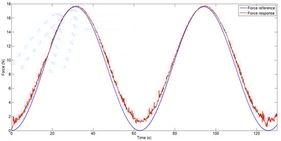
Figure 7.
Force-controlled actuator response.
As shown in Figure 7, after tuning the controller gains, the actuator is able to track the force reference. However, the force sensor signal exhibits significant noise, as no filtering was applied prior to acquisition. For this reason, to avoid amplifying the noise in the control loop, the derivative gain was significantly reduced. In this case, the error is more pronounced at low force levels, particularly near zero, where the actuator is not under mechanical tension—around 1.5 N. At higher force levels, such as 17.5 N, the error was approximately 0.15 N, corresponding to 0.85%. Additionally, a slight discrepancy can be observed during the cooling phase, where the actuator exhibits a slower response as a result of relying on passive heat dissipation to the ambient environment.
3.2. Exosuit Results
Following the tuning of the control algorithms on the test benches, the system was implemented in the exosuit and evaluated through trials with a healthy participant, a female subject, 35 years old, with the following upper limb segment lengths: 0.31 m arm, 0.25 m forearm, and 0.155 m hand. It is important to consider that, in this case, the load being displaced is the user’s own forearm, which varies depending on the elbow’s angular position. Furthermore, during the recovery phase, depending on patient-specific characteristics (such as body weight) and the elbow angle, the load applied during the actuator’s cooling phase may fall below the minimum recommended by the manufacturer. This is especially relevant considering that the actuator consists of three bundles, each composed of three 0.51 mm diameter wires.
To highlight the difference in actuator response between a single bundle of three wires and an actuator composed of three bundles (each with three wires) activated sequentially, two separate position control tests were conducted: the first using the actuator with a single bundle (see Figure 8), and the second using the actuator with three bundles (see Figure 9).
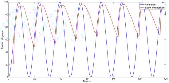
Figure 8.
Exosuit response when activating the actuator composed of a single bundle of three wires.
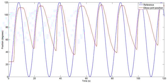
Figure 9.
Exosuit response with the proposed actuator composed of three bundles, each consisting of three wires, activated sequentially.
In both tests, the system was required to follow a sinusoidal position reference ranging from 0 (fully extended, considered the default state) to 120 degrees, with a frequency of approximately 0.065 Hz (one cycle every 15.5 s). The user did not apply any force during the test. From the perspective of SMA wire dynamics, this is considered a high frequency, as the manufacturer recommends 14 s solely for the cooling phase—implying a minimum of 28 s per full cycle. This frequency was chosen because it more closely resembles early-phase rehabilitation therapy, which typically involves slow, repetitive movements, and it allows for a clearer comparison of the performance between the two actuator configurations. It is also worth noting that if a lower frequency were used, the position error would be significantly reduced.
Figure 8 shows the exosuit’s position response while tracking a sinusoidal reference. As previously discussed, the position error during the cooling phase is significant, reaching up to 50 degrees in the first cycle and increasing with each subsequent cycle due to heat accumulation in the Bowden cable of the actuator. After 115 s, the position error during the cooling phase increased to 68 degrees. During the heating phase, the maximum error was 8.3%.
The second test, in which the exosuit was actuated using the proposed configuration of three bundles—each composed of three wires activated sequentially—is shown in Figure 9. Each bundle of wires is activated for one cycle, while the other two are left to cool down for two cycles. The duration of each cycle can be configured at the beginning of the test. If more force is required, all bundles can be activated simultaneously. In this case, the control system must be capable of synchronizing the activation of each wire bundle in such a way that the transition from one actuator to another is smooth and does not deviate from the reference trajectory. In this case, the position error decreased and did not increase significantly over time, as observed in the previous configuration. An angular position error between 36 and 45 degrees was observed, depending on which bundle was active (bundles under lower mechanical tension exhibited better performance during the cooling phase). During the heating phase, a similar position error of approximately 8.3% was observed. However, a study of the selected gains on the test bench and their sensitivity in the actual exosuit should be conducted. Nevertheless, due to the complexity of the design, including its nonlinearities, and considering that the system will be tested directly on the human body, this evaluation and subsequent gain adjustment would be challenging.
In both cases, the position error during the cooling phase could be reduced by introducing an actuator in an antagonistic configuration, which could assist in the recovery of the agonist actuator. Another alternative could be the use of elastic elements, such as springs or a silicone band, similar to the one proposed in [38], which could assist in the recovery phase.
To demonstrate the force assistance provided by the exosuit, two tests were conducted in which the muscle activity of the biceps was measured. In this case, one channel of the EMG device was used, capturing the signal via an analog port. The EMG signal was acquired at a sampling frequency of 500 Hz and then processed using a band-pass filter between 20 and 250 Hz to eliminate low-frequency noise (e.g., from cable movement) and high-frequency noise generated by the electronics. The 20–250 Hz range corresponds to the frequency band where muscle activity is most significant. After band-pass filtering, a 50 Hz notch filter was applied to remove power line interference (50 Hz in Europe), and the signal was then rectified by taking its absolute value. For improved visual interpretation, the signal envelope was extracted using a low-pass filter at 6 Hz.
In both tests, the user performed three repetitive flexion–extension movements while holding a 2.5 Kg weight. In the first case (see Figure 10), the exosuit was not activated, and the user provided all the force required to move the joint. In this case, the envelope of the sEMG reached values close to 60 units, with the highest peak observed during the first cycle. A higher amplitude in the sEMG signal indicates greater muscle activity, which is directly related to the amount of force exerted by the user.
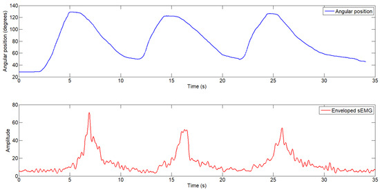
Figure 10.
Elbow joint angular position (top) and enveloped electromyography signal (bottom) during the test without exosuit assistance.
In the second test, the user performed the same task—moving a 2.5 kg load through flexion–extension—but in this case, with the exosuit activated, providing a constant assistive force of 12.2 N. Figure 11 shows the user’s elbow joint movement along with the enveloped sEMG signal. As observed, the amplitude of the sEMG signal decreases to approximately 40 units, indicating reduced muscular effort during the flexion movement.
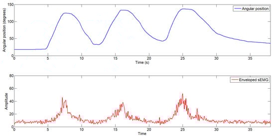
Figure 11.
Elbow joint angular position (top) and enveloped electromyography signal (bottom) during the test with exosuit assistance.
4. Discussion
Although exosuits do not restrict users’ movement as much as rigid exoskeletons, they still present several challenges, particularly due to the need for flexible materials compatible with the user, as well as lightweight and flexible actuators and sensors. Moreover, control strategies for such systems are more complex due to their inherent flexibility.
In this work, the obtained results show that the proposed actuator, based on multiple SMA wires, improves angular trajectory tracking at the elbow joint compared to traditional configurations using a single wire bundle. During the heating phase, the position error remained approximately 8.3%, while during the cooling phase, although the error increased, the sequential activation strategy partially mitigated this effect.
Although the temperature of the SMA wires can reach up to 90 °C, the temperature of the Bowden sheath reaches around 60 °C at the point where the SMA is in contact with both the Teflon wall and the Bowden tube wall. This was measured through simulation in a previous study [39]. Nevertheless, the Bowden tube is never in direct contact with the user’s skin, as it is enclosed within the exosuit. The most critical temperature point is located at the elbow joint, where the wires are not protected by the Bowden cable. However, during actuation, these wires will not come into contact with the exosuit due to the angle formed by the elbow during flexion. In the future, this section will be reinforced with improved thermal and electrical insulation.
sEMG tests demonstrated a notable reduction in muscle activity during assisted flexion, confirming the exosuit’s real contribution in terms of physical assistance.
However, some limitations remain. The actuator’s response during the cooling phase is still slow due to passive heat dissipation. This limits the maximum operating frequency, restricting its use in activities that require higher dynamic performance or shorter rehabilitation cycles. To improve this response, the future integration of an antagonistic actuator is proposed, which would actively support the recovery of the agonist actuator. This method was previously tested in a rigid structure [39] and in flexible structures [40,41].
Additionally, the cost and weight of the exosuit are among the main advantages of the proposed design. While the total weight of the exosuit is approximately 0.6 kg, the fabrication cost of this prototype does not exceed EUR 500.
Table 2 presents a quantitative comparison between our proposed exosuit and several representative elbow exosuits from the literature. The comparison includes key parameters such as actuation type, maximum torque (or actuator force), range of motion (ROM), total weight (or wearable component), and flexion speed (or maximum actuation frequency). As observed, systems actuated by DC motors—often transmitting force through Bowden cables—are significantly faster than those based on SMA, but are also heavier compared to SMA or pneumatic exosuits (at least when considering only the wearable components). In our case, one advantage of the proposed actuator is that the Bowden cable already integrates the actuation mechanism, eliminating the need for a backpack-mounted DC motor (and its associated weight), while achieving torque and force levels comparable to those of DC motor-driven systems. On the other hand, pneumatic systems offer low weight and fast actuation, but require a compressed air supply and precise position control.
Table 2.
Comparison with other rehabilitation devices.
Compared to other SMA-actuated exosuits presented in the literature, our system employs bundles of SMA wires housed in Bowden sheaths. This configuration offers certain advantages, such as providing more time for the SMA wires to cool down. Additionally, it allows for a slight reduction in the overall weight of the device.
On the other hand, the length of the SMA actuators in our system is longer compared to those that use SMA springs. However, due to the actuator’s flexibility, it can conform to the shape of the human body—either by being sewn directly into the actuated suit or coiled along the user’s back.
5. Conclusions
A novel soft exosuit for elbow flexion rehabilitation was successfully developed and validated, integrating a multi-bundle SMA actuator capable of both position and force control. The proposed actuator configuration was compared with a single-bundle SMA actuator, demonstrating that the multi-bundle system with sequential activation bundles improved dynamic response. The exosuit design emphasizes user comfort, low weight (0.6 kg), and cost-effectiveness (under 500 euros), making it a promising candidate for future clinical applications. Despite the positive outcomes, the actuator’s cooling phase remains a limiting factor. Future work will focus on integrating an antagonistic actuator to enhance recovery dynamics and overall system performance.
Author Contributions
Conceptualization, J.A.G.; methodology, J.A.G.; software, J.A.G. and A.P.-C.P.; validation, J.A.G. and A.P.-C.P.; formal analysis, J.A.G.; data curation, J.A.G.; investigation, J.A.G. and D.C.; resources, J.A.G. and D.C.; writing—original draft preparation, D.C. and J.A.G.; writing—review and editing, J.A.G. and D.C.; visualization, D.C.; supervision, D.C. and D.B.R.; project administration, D.B.R. and D.C.; funding acquisition, D.B.R. and D.C. All authors have read and agreed to the published version of the manuscript.
Funding
This research is part of the project Robótica blanda para la rehabilitación del tobillo (SRAR), I+D+i grant PID2023-149141OB-I00, funded by MCIN/AEI/10.13039/501100011033 and by FEDER/UE.
Data Availability Statement
The data presented in this study are available on request from the corresponding author.
Conflicts of Interest
The authors declare no conflicts of interest. The founders had no role in the design of the study; in the collection, analyses, or interpretation of data; in the writing of the manuscript; or in the decision to publish the results.
References
- World Heart Organization. World Heart Organization—Stroke, Cerebrovascular Accident. 2025. Available online: https://www.emro.who.int/health-topics/stroke-cerebrovascular-accident/index.html (accessed on 2 April 2025).
- World Stroke Organization. World Stroke Organization—Impact of Stroke. 2025. Available online: https://www.world-stroke.org/world-stroke-day-campaign/about-stroke (accessed on 2 April 2025).
- Carlsson, H.; Gard, G.; Brogårdh, C. Upper-limb sensory impairments after stroke: Self-reported experiences of daily life and rehabilitation. J. Rehabil. Med. 2018, 50, 45–51. [Google Scholar] [CrossRef]
- Schaechter, J.D. Motor rehabilitation and brain plasticity after hemiparetic stroke. Prog. Neurobiol. 2004, 73, 61–72. [Google Scholar] [CrossRef]
- Pérez Vidal, A.F.; Rumbo Morales, J.Y.; Ortiz Torres, G.; Sorcia Vázquez, F.d.J.; Cruz Rojas, A.; Brizuela Mendoza, J.A.; Rodríguez Cerda, J.C. Soft Exoskeletons: Development, Requirements, and Challenges of the Last Decade. Actuators 2021, 10, 166. [Google Scholar] [CrossRef]
- Huang, W.; Feng, M.; Yang, D.; Gu, G. Low-resistance, high-force, and large-ROM fabric-based soft elbow exosuits with adaptive mechanism and composite bellows. Sci. China Technol. Sci. 2023, 66, 24–32. [Google Scholar] [CrossRef]
- Xie, D.; Su, Y.; Shi, X.; Tong, S.F.; Li, Z.; Kai-yu Tong, R. A Compact Elbow Exosuit Driven by Pneumatic Artificial Muscles. IEEE Robot. Autom. Lett. 2024, 9, 3331–3338. [Google Scholar] [CrossRef]
- Alapati, S.; Seth, D.; Nakka, S.; Aoustin, Y. Validation of Cable-Driven Experimental Setup to Assess Movements Made with Elbow Joint Assistance. Appl. Sci. 2025, 15, 1892. [Google Scholar] [CrossRef]
- Liu, Q.; Liu, Y.; Zhu, C.; Guo, X.; Meng, W.; Ai, Q.; Hu, J. Design and Control of a Reconfigurable Upper Limb Rehabilitation Exoskeleton With Soft Modular Joints. IEEE Access 2021, 9, 166815–166824. [Google Scholar] [CrossRef]
- Shen, Y.; Dang, Y.; Jiang, T.; Huo, W.; Yu, N.; Han, J. A Textile-Based Pneumatic Soft Suit for Elbow Joint Rehabilitation. In Proceedings of the 2024 IEEE 14th International Conference on CYBER Technology in Automation, Control, and Intelligent Systems (CYBER), Copenhagen, Denmark, 16–19 July 2024; pp. 662–667. [Google Scholar] [CrossRef]
- Copaci, D.; Arias, J.; Moreno, L.; Blanco, D. Shape memory alloy (SMA)-based exoskeletons for upper limb rehabilitation. In Rehabilitation of the Human Bone-Muscle System; IntechOpen: Rijeka, Croatia, 2022. [Google Scholar]
- Shami, Z.; Arslan, T.; Lomax, P. Wearable Soft Robots: Case Study of Using Shape Memory Alloys in Rehabilitation. Bioengineering 2025, 12, 276. [Google Scholar] [CrossRef]
- Xie, Q.; Meng, Q.; Yu, W.; Xu, R.; Wu, Z.; Wang, X.; Yu, H. Design of a soft bionic elbow exoskeleton based on shape memory alloy spring actuators. Mech. Sci. 2023, 14, 159–170. [Google Scholar] [CrossRef]
- Jeong, J.; Hyeon, K.; Jang, S.Y.; Chung, C.; Hussain, S.; Ahn, S.Y.; Bok, S.K.; Kyung, K.U. Soft Wearable Robot With Shape Memory Alloy (SMA)-Based Artificial Muscle for Assisting With Elbow Flexion and Forearm Supination/Pronation. IEEE Robot. Autom. Lett. 2022, 7, 6028–6035. [Google Scholar] [CrossRef]
- Nordin, M.; Frankel, V.H. Basic Biomechanics of the Musculoskeletal System; Lippincott Williams & Wilkins: Philadelphia, PA, USA, 2001. [Google Scholar]
- Copaci, D.; Cano, E.; Moreno, L.; Blanco, D. New design of a soft robotics wearable elbow exoskeleton based on shape memory alloy wire actuators. Appl. Bionics Biomech. 2017, 2017, 1605101. [Google Scholar] [CrossRef] [PubMed]
- Liu, Q.; Ghodrat, S.; Huisman, G.; Jansen, K.M. Shape memory alloy actuators for haptic wearables: A review. Mater. Des. 2023, 233, 112264. [Google Scholar] [CrossRef]
- Taylor, F.; Au, C. Forced air cooling of shape-memory alloy actuators for a prosthetic hand. J. Comput. Inf. Sci. Eng. 2016, 16, 041004. [Google Scholar] [CrossRef]
- Bishay, P.; Aguilar, C.; Amirbekyan, A.; Vartanian, K.; Arjon-Ramirez, M.; Pucio, D. Design of a lightweight shape memory alloy stroke-amplification and locking system in a transradial prosthetic arm. In Proceedings of the Smart Materials, Adaptive Structures and Intelligent Systems. American Society of Mechanical Engineers, Virtual, 14–15 September, 2021; Volume 85499, p. V001T05A015. [Google Scholar]
- Xie, Q.; Meng, Q.; Yu, W.; Wu, Z.; Xu, R.; Zeng, Q.; Zhou, Z.; Yang, T.; Yu, H. Design of a SMA-based soft composite structure for wearable rehabilitation gloves. Front. Neurorobot. 2023, 17, 1047493. [Google Scholar]
- Sadeghi, M.; Abbasimoshaei, A.; Kitajima Borges, J.P.; Kern, T.A. Numerical and Experimental Study of a Wearable Exo-Glove for Telerehabilitation Application Using Shape Memory Alloy Actuators. Actuators 2024, 13, 409. [Google Scholar] [CrossRef]
- Riccio, A.; Sellitto, A.; Battaglia, M. Morphing Spoiler for Adaptive Aerodynamics by Shape Memory Alloys. Actuators 2024, 13, 330. [Google Scholar] [CrossRef]
- Brasoveanu, F.A.; Burlacu, A. Towards independent SMA actuators: A novel analog two-state control system for flexible robots. In Proceedings of the 2023 IEEE 28th International Conference on Emerging Technologies and Factory Automation (ETFA), Sinaia, Romania, 12–15 September, 2023; pp. 1–4. [Google Scholar]
- Guadalupe, J.A.; Copaci, D.; Navarro, P.M.; Moreno, L.; Blanco, D. A novel multi-wire SMA-based actuator with high-frequency displacement. Mechatronics 2023, 91, 102957. [Google Scholar] [CrossRef]
- Dynalloy. Technical Information/Technical Data/Technical Wire Data. 2025. Available online: https://dynalloy.com/ (accessed on 2 May 2025).
- Plagenhoef, S.; Evans, F.G.; Abdelnour, T. Anatomical data for analyzing human motion. Res. Q. Exerc. Sport 1983, 54, 169–178. [Google Scholar] [CrossRef]
- ST. Discovery kit with STM32F407VG MCU. 2025. Available online: https://www.st.com/ (accessed on 2 May 2025).
- ST. STP310N10F7. 2025. Available online: https://www.st.com/resource/en/datasheet/stp310n10f7.pdf (accessed on 2 May 2025).
- ams. ams AS5045 Rotary Sensor. 2025. Available online: https://ams-osram.com/products/sensor-solutions/position-sensors/ams-as5045-rotary-sensor (accessed on 2 May 2025).
- interlink. FSR 404 Force Sensing Resistor. 2025. Available online: https://www.interlinkelectronics.com/fsr-404 (accessed on 2 May 2025).
- Bioelettronica, O. Quattro. 2025. Available online: https://otbioelettronica.it/ (accessed on 2 May 2025).
- Orliman. Shoulder Brace. 2025. Available online: https://www.orliman.com/en/producto/neoprene-shoulder-support-4801/ (accessed on 2 May 2025).
- PULS. Power Supply. 2025. Available online: https://www.pulspower.com/ (accessed on 21 June 2025).
- Chang, B.C.; Shaw, J.A.; Iadicola, M.A. Thermodynamics of shape memory alloy wire: Modeling, experiments, and application. Contin. Mech. Thermodyn. 2006, 18, 83–118. [Google Scholar] [CrossRef]
- Theren, B.; Heß, P.; Bracke, S.; Kuhlenkötter, B. The development and verification of a simulation model of shape-memory alloy wires for strain prediction. Crystals 2022, 12, 1121. [Google Scholar] [CrossRef]
- Hedrea, R.C.R.; Petriu, E.M. Evolving fuzzy models of shape memory alloy wire actuators. Sci. Technol. 2021, 24, 353–365. [Google Scholar]
- Martineau, S.; Burnham, K.; Minihan, J.; Marcroft, S.; Andrews, G.; Heeley, A. Application of a bilinear PID compensator to an industrial furnace. IFAC Proc. Vol. 2002, 35, 25–30. [Google Scholar] [CrossRef]
- Bishay, P.L.; Fontana, J.; Raquipiso, B.; Rodriguez, J.; Borreta, M.J.; Enos, B.; Gay, T.; Mauricio, K. Development of a biomimetic transradial prosthetic arm with shape memory alloy muscle wires. Eng. Res. Express 2020, 2, 035041. [Google Scholar] [CrossRef]
- Copaci, D.; Martin, F.; Moreno, L.; Blanco, D. SMA based elbow exoskeleton for rehabilitation therapy and patient evaluation. Ieee Access 2019, 7, 31473–31484. [Google Scholar] [CrossRef]
- Mansilla Navarro, P.; Copaci, D.; Arias, J.; Blanco Rojas, D. Design of an SMA-Based Actuator for Replicating Normal Gait Patterns in Pediatric Patients with Cerebral Palsy. Biomimetics 2024, 9, 376. [Google Scholar] [CrossRef]
- Mansilla Navarro, P.; Copaci, D.; Blanco Rojas, D. Design and control of a soft knee exoskeleton for pediatric patients at early stages of the walking learning process. Bioengineering 2024, 11, 188. [Google Scholar] [CrossRef]
- Xiloyannis, M.; Annese, E.; Canesi, M.; Kodiyan, A.; Bicchi, A.; Micera, S.; Ajoudani, A.; Masia, L. Design and validation of a modular one-to-many actuator for a soft wearable exosuit. Front. Neurorobot. 2019, 13, 39. [Google Scholar] [CrossRef]
- Ismail, R.; Ariyanto, M.; Perkasa, I.A.; Adirianto, R.; Putri, F.T.; Glowacz, A.; Caesarendra, W. Soft Elbow Exoskeleton for Upper Limb Assistance Incorporating Dual Motor-Tendon Actuator. Electronics 2019, 8, 1184. [Google Scholar] [CrossRef]
- Park, S.J.; Park, C.H. Suit-type wearable robot powered by shape-memory-alloy-based fabric muscle. Sci. Rep. 2019, 9, 9157. [Google Scholar] [CrossRef]
Disclaimer/Publisher’s Note: The statements, opinions and data contained in all publications are solely those of the individual author(s) and contributor(s) and not of MDPI and/or the editor(s). MDPI and/or the editor(s) disclaim responsibility for any injury to people or property resulting from any ideas, methods, instructions or products referred to in the content. |
© 2025 by the authors. Licensee MDPI, Basel, Switzerland. This article is an open access article distributed under the terms and conditions of the Creative Commons Attribution (CC BY) license (https://creativecommons.org/licenses/by/4.0/).