Abstract
This study investigates the external load and positional constraints’ impact on the accuracy and performance of an autonomous adaptive electrohydraulic actuator with pump control intended for mobile equipment. An actuator simulation model was developed in the MATLAB/Simulink (version R2021A) environment, and a full-scale experimental setup was constructed to validate this model. Various motion trajectories under different load conditions were analyzed to evaluate discrepancies between simulated and experimental results and to identify key performance characteristics across operational modes. The results demonstrate that the simulation model adequately replicates the actuator’s dynamic behavior, although deviations emerge under high-load conditions. Notably, in the absence of external load, the static positioning error does not exceed 0.025 mm (0.05% of the 50 mm target value), while under the maximum load of 8000 N, the error increases to 0.075 mm (0.15% of the 50 mm target value). These limitations are primarily due to current constraints imposed by the actuator’s power supply capacity (up to 300 W at 24 V), which restrict pressure buildup rates under heavy loads. Nevertheless, the proposed control system exhibits robustness to load variations and ensures positioning accuracy within acceptable limits, demonstrating its practical suitability for mobile machinery applications. The developed simulation model also serves as a valuable tool for control system tuning and testing in the absence of a physical prototype.
1. Introduction
With the rapid development of automated production systems, there is a growing need for actuator systems that are highly accurate, energy-efficient, and adaptable to variable operating conditions. This issue is particularly pronounced in fields such as mechanical engineering, agriculture, robotics, and mobile technology, where executive equipment is subjected to dynamically changing loads and necessitates stable positioning [1,2,3].
Despite their high specific power, traditional hydraulic actuators are characterized by significant energy losses during throttle flow control and have complicated adjustment processes with insufficient accuracy when operating in dynamic modes [4,5,6]. In turn, electro-mechanical systems are inferior to traditional hydraulic drives in terms of energy consumption and stability to external disturbances, especially under severe operating conditions.
Electrohydraulic actuators (EHAs) offer a promising approach, utilizing pump control to achieve positional regulation via modulation of the pump unit drive speed. These solutions eliminate throttle losses and ensure high positioning accuracy [7,8].
Current research into EHA systems emphasizes the need to improve positioning accuracy, energy efficiency, and control system adaptability. However, several studies have revealed significant limitations in existing solutions, emphasizing the need to develop simpler EHA architectures that can maintain high levels of accuracy and repeatability.
In the study [9], a hydraulic actuator with an independent flow metering system is considered, in which an adaptive control strategy is implemented, considering the hydraulic actuator speed constraints and a non-deterministic load. Employing a deterministic robust controller under constrained conditions revealed a 25 mm positioning error across the entire displacement trajectory in response to an external load.
The paper by Nie et al. [10] is devoted to developing a control system for an underwater electro-hydrostatic actuator that considers a pressure compensator and external load. The authors proposed a nonlinear model that considers compensator dynamics and implemented a backstepping controller with extended state observers. This achieved a positioning error of less than 0.05 mm in a simulated environment. However, the study is limited to modeling and does not include experimental verification. Furthermore, the effect of the load on control accuracy is not investigated directly.
In paper [11], the authors study the positional control of a hydraulic cylinder with a one-way piston that is controlled by a servo valve under the condition of a constant external load. They implement the control using a fuzzy PID controller and carry out modeling and experimentation using stepwise command actions with different displacement amplitudes. The transient parameters analyzed are delay time, settling time, overshoot, and static error, the latter of which varies from 0.06% to 0.15%.
The study [12] presents a model of an electrohydraulic actuator with a bidirectional hydraulic lock (BHL-EHA). This model is used to analyze positioning delays that arise from using hydraulic locks for energy-saving purposes. The authors discuss the factors affecting the magnitude of the delay in detail, as well as its impact on positioning accuracy. The positioning error is less than 3% in the dynamic mode and less than 0.5% in the stationary mode.
Several studies have highlighted the drawbacks of pump-controlled systems, which require additional energy inputs in static mode—particularly when EHAs with fixed pump displacement and variable motor speed are used. Despite their compactness and high energy density, such systems can be inefficient when the load is stationary because the pump continues to operate to maintain pressure, resulting in excessive energy consumption and motor heating. Circuit solutions to this issue are presented in papers [10,13,14,15].
In light of the above, the aim of this study is to investigate the impact of external load and positioning cycle characteristics on the positioning accuracy of a pump-controlled electrohydraulic actuator. The research considers a circuit design that enables reduced energy consumption during static load holding and improved positioning accuracy without significantly increasing system complexity. To quantitatively assess the effects of load and positional constraints on actuator performance, a comprehensive analysis based on simulation modeling and experimental testing was conducted. The results confirm the effectiveness of the proposed approach and highlight its potential for use in mobile equipment and other systems operating under variable external conditions.
The scientific novelty of the work lies in the development of a new drive design and its mathematical model, which allows one to evaluate (or study) the influence of external load and characteristics of the positioning cycle on the positioning accuracy of an electrohydraulic drive with pump control, as well as to optimize its design parameters and control algorithms when designing for a specific technical task.
2. Materials and Methods
To achieve this goal, this study presents the development of an electrohydraulic actuator with a one-way rod, analyzing its dynamic characteristics based on a developed mathematical model and the results of field experiments [16,17,18,19,20]. The structural diagram of the proposed system is shown in Figure 1.
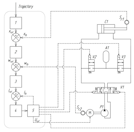
Figure 1.
Structural diagram of an electrohydraulic actuator: (1) reference trajectory generator; (2) position regulator; (3) angular speed regulator; (4) current controller; (5) power electronics and valve control unit; (P1) hydraulic pump; (M) DC electric motor; (V1) 3-position 4-way directional valve; (V2 and V3) 2-position 2-way directional valves; (C1) hydraulic cylinder; (Sr1) displacement sensor; (Sr2) rotation sensor; (A1) hydraulic accumulator.
The schematic represents a controlled electro-hydro-mechanical servo system with feedback, designed to actuate a single degree of freedom. The system features a simple and energy-efficient architecture, incorporating a minimal number of hydraulic components and a rational layout. Unlike other solutions [21,22,23], this configuration reduces energy consumption during steady-state operation when holding a load without movement, due to the use of directional control valve V1. The working lines of the pump P1 are not connected to the hydraulic cylinder C1 directly, but via the directional control valve V1. This design prevents continuous fluid circulation when the actuator output remains stationary, thereby reducing energy losses in the load-holding mode.
Due to the asymmetry of the hydraulic cylinder, 2-position valves (V2 and V3) are used to supply additional oil from the A1 battery or to discharge some oil into the battery. This compensates for the difference in volume between the piston and rod chambers.
The reference position coordinate of the rod xref, generated by the control signal processing block 1, and the actual rod position xfb, obtained via the feedback line from the position sensor Sr1, form the position error signal, which is fed to regulator 2. At the output of regulator 2, a reference control signal for the motor rotational speed wref is generated. The motor speed error signal ew(t) = wref − wfb is then input into regulator 3, where wfb is the actual motor speed, obtained from the feedback line connected to the speed sensor Sr2.
The output of regulator 3 provides the reference signal for the current control loop Iref. The difference between Iref and the actual current value Ifb, received via the feedback line, is applied to regulator 4. The control action from regulator 4 is directed to block 5, which performs the functions of generating the voltage applied to the motor windings, measuring the motor current, and controlling the hydraulic directional valves.
2.1. Mathematical Model
The generalized mathematical model of the electrohydraulic actuator has been developed, considering the conditions and modes of its operation, as well as the peculiarities of the load. Modeling of the processes occurring during the actual operation of the EHA is complicated by the unsteadiness of the working fluid flows and the instability of the actual effects on the system; to simplify the mathematical model, the following assumptions were made: the characteristics of the working fluid (density, viscosity, Reynolds number, flow coefficient, etc.) are constant in all modes of operation of the EHA; flow coefficients and volumetric modulus of elasticity fluids are constant; pipelines and hydraulic channels of the EHA are absolutely rigid; liquid pressure and flow rate are values concentrated in volumes determined by the calculation scheme; pressure losses due to local and linear hydraulic resistances of small and large diameters are not taken into account; and temperature effects and related changes in the properties of the material and liquid are not taken into account, as well as the phenomena of water hammer and other related factors. The model does not take into account the phenomenon of cavitation. Absolute pressure values were used in the calculations [21,24,25,26].
In this study, a method of pump shaft speed control was used to implement hydraulic servo systems to control the position of the actuator stem. The calculation scheme of the EHA is shown in Figure 2.
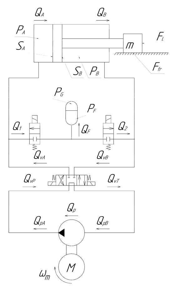
Figure 2.
Calculation scheme of the electrohydraulic actuator.
Given that the output shaft of the electric motor is connected to the gear pump via a coupling, the angular speed of rotation of the pump is equal to that of the electric motor (1).
- where —angular speed of rotation of the pump [rad/s];
- —angular speed of rotation of the electric motor [rad/s].
The pump flow equation is determined by Equations (2)–(4):
- where Dp—pump displacement [m3/rad];
- Cip—coefficient of internal volumetric losses in the pump [m5/(N·s)];
- Cep—coefficient of external volumetric losses in the pump [m5/(N·s)];
- PA, PB—pressures in the piston and rod chambers of the hydraulic cylinder [Pa].
In order to draw up equations of hydraulic fluid flow rates in the hydraulic directional control valve, a calculation scheme of the hydraulic distributor was drawn up, as shown in Figure 3.
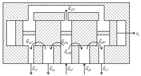
Figure 3.
Calculation scheme of the hydraulic directional control valve.
The system of Equation (5) describes the flow rates of the working fluid through the hydraulic valve as a function of the control signal (spool displacement), the pressure at the valve inlet , the pressures in the working lines and , and the pressure in the return line .
- where —flow rate of hydraulic fluid from valve channel A [m3/s];
- —flow rate of hydraulic fluid from valve channel B [m3/s];
- —total flow rate into the valve [m3/s];
- —total flow rate to the tank [m3/s];
- —flow rate from the pressure line to channel A through the valve [m3/s];
- —flow rate from the pressure line to channel B through the valve [m3/s];
- —flow rate from channel A to the tank [m3/s];
- —flow rate from channel B to the tank [m3/s];
- —flow rate from port P to port T [m3/s];
- —flow coefficient;
- —function defining the effective flow area depending on the spool position [m2].
The ratio of pressure and volume of gas in the operating state and pre-charge state is determined by the polytropic relation with the pressure of the liquid bringing the diaphragm of the hydraulic accumulator to the balanced co-state according to Equation (6).
- where PG—gas pressure in the gas chamber [Pa]; PG0—gas pressure in the chamber when the hydraulic cavity of the accumulator is empty [Pa]; Patm—atmospheric pressure [Pa];
- VT—total volume of the accumulator [m3]; VG—volume of the gas chamber [m3];
- ksh—adiabatic index.
The pressure in the hydraulic cavity of the accumulator is determined by Equation (7):
where PHS—pressure of the mechanical stop [Pa], determined by Equation (8).
The flow rate of fluid into the accumulator is determined by Equation (9).
The force balance equation, representing the relationship between load and output force of the hydraulic cylinder, is given by the following:
where xp—piston position [m]; m—total mass of the piston and the load [kg]; b—viscous damping coefficient [N/(m·s)]; FL—external load force [N]; Ffr—friction force [N].
The equations of pressure change in the working fluid in the hydraulic cylinder have the following form:
- where SA, SB—piston and rod side areas [m2];
- VA, VB—hydraulic cylinder chamber volumes: VA(xp) = VA0 + SA·xp,
- VB (xp) = VB0 − SB·xp [m3];
- βe—bulk modulus of the system [N/m2];
- Cic—internal leakage coefficient of the cylinder [m5/(N·s)];
- PcA, PcB—pressures in the cylinder chambers [Pa].
The flow balance in the hydraulic system is described by the system of Equation (13).
- where , —fluid compressibility flows in cylinder chambers [m3/s];
- —compressibility flow in the hydraulic accumulator [m3/s];
- , —compressibility flows in distributor channels [m3/s];
- , —compensation flows due to volume difference between cylinder chambers [m3/s].
2.2. Simulation Modeling
Currently, the widespread development of virtual prototyping technologies and engineering software allows for modeling and preliminary evaluation of the performance characteristics of systems without conducting field experiments. This helps to reduce production costs, reduces the number of possible errors, and increases the consistency of design decisions [27,28,29].
The EHA control system contains equipment related to controlling the position of the hydraulic cylinder. The controller is implemented as a discrete PID controller using a set of blocks of the MATLAB/Simulink PID library (Figure 4). The resulting mathematical model of the EHA was solved using MATLAB/Simulink (version R2021A) physical system modeling tools.
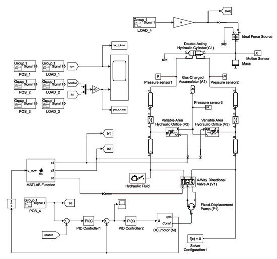
Figure 4.
Simulation model of an electrohydraulic linear actuator in MATLAB/Simulink.
The operability of the control system and the reliability of the computational experiment are confirmed by solving the system of equations using the ode23t method, which is an implicit trapezoidal method of interpolation [30]. This method gives good results in solving problems describing oscillatory systems with an almost harmonic output signal.
2.3. Experimental Modeling
To conduct a full-scale experiment, a stand was created (Figure 5), which makes it possible to determine the characteristics of a prototype electrohydraulic actuator and confirm the adequacy of the simulation model.
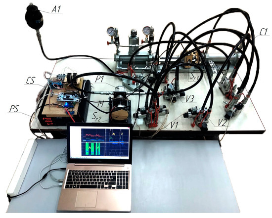
Figure 5.
The appearance of the experimental installation of an electrohydraulic actuator.
The main elements of the stand are hydraulic pump (P1); DC electric motor (M); control system (CS); power supply unit (PS); 3-position 4-way directional valve (V1); 2-position 2-way directional valves (V2, V3); hydraulic cylinder (C1); displacement sensor (incremental optical encoder) (Sr1); rotation sensor (absolute magnetic encoder) (Sr2); and hydraulic accumulator (A1). The control system operates the electric motor and the two-position directional control valves, whose switching enables the connection of the piston and rod chambers to the accumulator. An optical sensor mounted on the hydraulic cylinder rod is used as a displacement sensor. The sensor provides measurements with an accuracy of 0.025 mm. The driver is connected to the computer via the RS-485 interface using the ModBus RTU protocol, which is used to set the motion trajectory and transmit data such as rod displacement, electric motor rotational speed, and other parameters. Additionally, communication can also be established via the Ethernet interface for higher-speed data exchange and system integration.
Based on the practical requirements for mobile technology equipment, the power allocated to the actuator is limited by the power of the on-board power supply system of 300 Watts at a supply voltage of 24 V DC.
As part of the development of the EHA, an EHA control system (CS) based on the STM32F767ZI microcontroller (STMicroelectronics, Calamba, Philippines) was developed, manufactured, and tested. In addition to the possibility of controlling the electric motor, this control system is equipped with ports for connecting an encoder and analog sensors, and has communication ports such as TTL-UART and RS-485, which support data exchange rates up to 921,600 Baud.
The electromagnets of the distributors V1, V2, and V3 are activated by switching the corresponding electromagnetic relays, which are controlled via the digital outputs of the microcontroller. The speed of rotation of the electric motor is controlled using a specially designed driver, the input of which is supplied with a PWM signal generated by one of the microcontroller’s timers. The PWM generation frequency is 20 kHz. The pressure and current sensors are connected to the analog inputs of the microcontroller via operational amplifiers. The control algorithms in the control system are processed with a period of 1 ms set by a hardware timer, which ensures the strictly deterministic execution of all control cycles and sensor polling in real time. The microcontroller’s peripherals were configured in the STM32CubeMX program (version 6.2.1). The EGA algorithms were written in the C programming language in the SW4STM32 development environment (version 41).
The control system allows one to collect data on processes in the system and parameters such as the position and speed of the actuator stem obtained from the encoder, pressure in the rod and piston cavities of the cylinder, the values of the voltage and current of the electric motor coming from the corresponding sensors to the driver board, and internal control system variables. The availability of such data makes it possible to restore a complete and reliable picture of the ongoing dynamic processes in the EGA, perform research, build models, test hypotheses and algorithms, and optimize devices and algorithms.
3. Results and Discussions
To evaluate the control system of the simulation model and the experimental stand, movement trajectories with different positional cycle coordinates (XCPC) under different loads were set. As shown in Figure 6, Figure 7, Figure 8 and Figure 9, the control effect of the regulator on the simulation model is compared with the data obtained on the experimental stand. Figure 5 shows the results when there is no load. Figure 6 shows the results with a load of 4000 N. Figure 7 shows the results with a load of 6000 N. Figure 8 shows the results with a load of 8000 N.
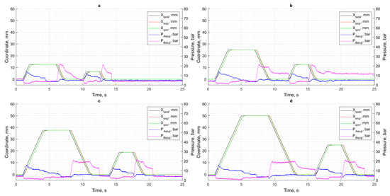
Figure 6.
Results of motion control in the absence of load: (a) XCPC = 12.5 mm; (b) XCPC = 25 mm; (c) XCPC = 37.5 mm; (d) XCPC = 50 mm.
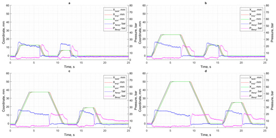
Figure 7.
Displacement control results at 4000 N load: (a) XCPC = 12.5 mm; (b) XCPC = 25 mm; (c) XCPC = 37.5 mm; (d) XCPC = 50 mm.
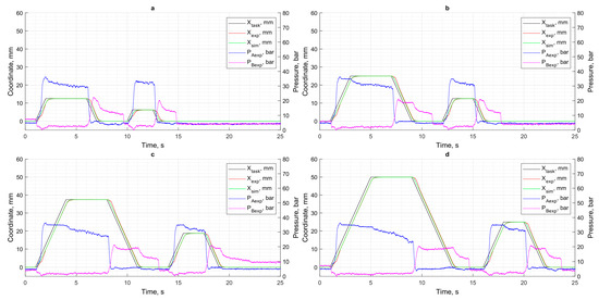
Figure 8.
Displacement control results at 6000 N load: (a) XCPC = 12.5 mm; (b) XCPC = 25 mm; (c) XCPC = 37.5 mm; (d) XCPC = 50 mm.
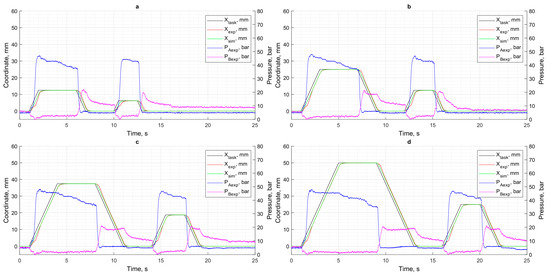
Figure 9.
Displacement control results at 8000 N load: (a) XCPC = 12.5 mm; (b) XCPC = 25 mm; (c) XCPC = 37.5 mm; (d) XCPC = 50 mm.
Figure 10 shows the control errors for different trajectories and different loads. The control error is the difference between the trajectory obtained and the set trajectory. The control error is calculated for the data obtained from the simulation model and for the data obtained from the experiment. The observed discrepancies between the simulated and experimental responses can be attributed not only to actuator dynamics and controller limitations, but also to additional physical effects not fully captured in the simulation model.
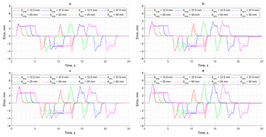
Figure 10.
Control error: (a) FLoad = 0 N; (b) FLoad = 4000 N; (c) FLoad = 6000 N; (d) FLoad = 8000 N.
In particular, the experimental setup includes relatively long hydraulic lines, which introduce additional compliance and delay into the system due to increased fluid compressibility and frictional pressure losses. Furthermore, temperature rise during prolonged operation leads to a reduction in fluid viscosity, thereby altering flow characteristics and affecting system damping and responsiveness. Another significant factor is the possible presence of air in the hydraulic circuit, which increases the effective compressibility of the working fluid, resulting in slower pressure buildup and degraded positioning precision. These combined effects contribute to the slightly higher positioning errors observed in the experimental setup compared to the idealized simulation environment.
Figure 11 shows the difference in displacement trajectories between the simulation model and the physical prototype under various loads and different set coordinates of the positioning cycle (XCPC). Based on the data presented in Figure 10 and Figure 11, it can be noted that the positioning error and minor discrepancies between the simulation results and the experimental setup are primarily caused by actuation delays in the hydraulic components, as confirmed by other studies [12,31,32].
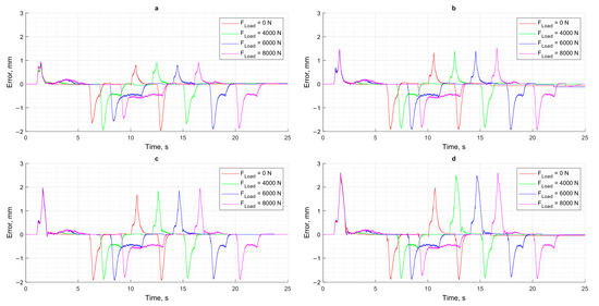
Figure 11.
The difference between the trajectories of the simulation model and the physical model: (a) XCPC = 12.5 mm; (b) XCPC = 25 mm; (c) XCPC = 37.5 mm; (d) XCPC = 50 mm.
A comparison of the simulation results with the data obtained from the test bench shows that the greatest discrepancies occur under high load conditions. As shown in the pressure graphs (Figure 6, Figure 7, Figure 8 and Figure 9), this mode is characterized by a significant increase in pressure in the piston chamber, which leads to intensified internal leakage in the pump and overload of the DC motor.
An analysis of the motor speed graphs (Figure 12)—and therefore the pump speed—shows that under loads of 6000 N and 8000 N, the angular velocity of the motor temporarily decreases and then begins to increase, thereby generating the required pressure in the piston chamber of the hydraulic cylinder and ensuring the necessary motion dynamics. At the same time, the positioning error remains minor and within acceptable limits, confirming the effectiveness of the adaptive control strategy under variable load and displacement amplitude conditions.
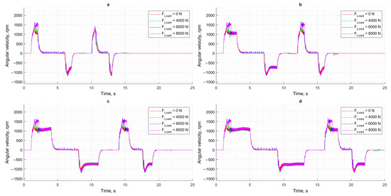
Figure 12.
Angular velocity of DC motor: (a) XCPC = 12.5 mm; (b) XCPC = 25 mm; (c) XCPC = 37.5 mm; (d) XCPC = 50 mm.
A similar dynamic behavior is observed in the rod displacement velocity graphs (Figure 13), where sudden increases in load cause brief decelerations, which are quickly compensated by the control system. This demonstrates the system’s robustness to external disturbances and its ability to maintain the desired motion trajectory with high accuracy.
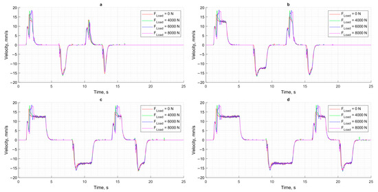
Figure 13.
The speed of movement of the cylinder rod at different loads: (a) XCPC = 12.5 mm; (b) XCPC = 25 mm; (c) XCPC = 37.5 mm; (d) XCPC = 50 mm.
Based on the data obtained above, the positioning error was evaluated as a function of the applied load and the specified coordinate of the positioning cycle (Figure 14). The dependence of the settling time on the applied load and the setpoint coordinate of the positioning cycle is shown in Figure 15.
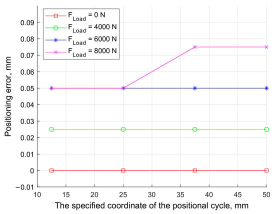
Figure 14.
The dependence of the static positioning error on the set coordinate of the positional cycle under various loads.
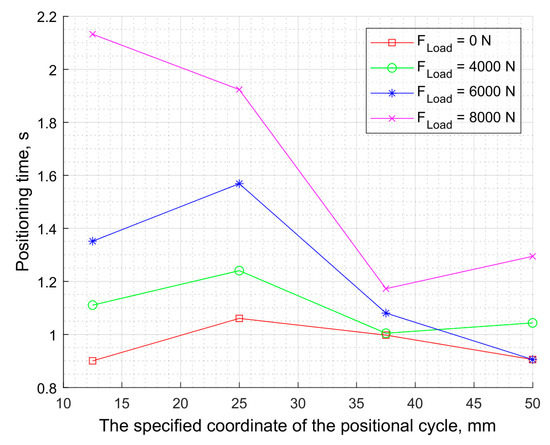
Figure 15.
The dependence of the control time on the set coordinate of the positional cycle at different loads.
As shown in Figure 14, in the absence of an external load, the static positioning error is 0.025 mm, which corresponds to 0.05% of the target position value of 50 mm. As the load increases, the positioning error naturally grows; however, even at the maximum load of 8000 N, it does not exceed 0.075 mm, which corresponds to 0.15% of the target value.
An analysis of the settling time graph indicates that the positioning time of the actuator rod increases with the applied load. In the no-load condition, the delay varies between 0.9 and 1.05 s, depending on the positioning cycle setpoint. At a load of 8000 N and a target position of 12.5 mm, the delay increases to 2.12 s. This is primarily due to the saturation of the controller’s output when the required control action exceeds its limits. Additionally, the limited power capacity of the actuator hardware, which is constrained by the design requirements of mobile equipment, also contributes to this behavior.
4. Conclusions
In this study, a simulation model of an electrohydraulic actuator was implemented in the MATLAB/Simulink environment, and a full-scale experiment was conducted on a specially designed bench. To evaluate the behavior of the control system, different linear trajectories of displacement under different external loads were set. Analysis of deviations between the specified and obtained trajectories, as well as between the data of modeling and experimental results, allowed us to identify the key characteristics of the system functioning in different modes.
The comparison showed that the developed simulation model, despite some discrepancies with the experimental data, adequately reflects the dynamics of the system functioning. However, the parameterization of the model solely on the basis of the characteristics of individual components limits its applicability for precise control optimization, especially in conditions of variable loads. Nevertheless, the model is of considerable practical value in the absence of a physical prototype, providing a basis for preliminary debugging of control systems and testing.
The analysis of the influence of external load showed that with its increase, there was a natural growth of both positioning time and positioning error. Thus, at a load of 8000 N, the static error in the steady-state mode was 0.075 mm, which is equivalent to about 0.15% of the maximum coordinate of the positioning cycle. The positioning time increased at the same time.
Although the actuator design and test conditions were tailored to mobile machinery constraints, the proposed control system and modeling approach can be generalized and adapted for other domains requiring compact, energy-efficient, and load-resilient positioning systems, such as robotic arms, agricultural implements, and industrial manipulators.
Author Contributions
Conceptualization, E.I., V.G. and D.M.; methodology, E.I. and V.G.; software, V.G.; validation, E.I., V.G. and D.M.; formal analysis, E.I., V.G. and D.M.; investigation, E.I., V.G. and D.M.; resources, E.I., V.G. and A.N.B.; data curation, E.I., V.G. and D.M.; writing—original draft preparation, E.I., V.G. and A.N.B.; writing—review and editing, E.I., V.G. and A.N.B.; visualization, E.I., V.G. and D.M.; supervision, A.N.B.; project administration, A.N.B.; funding acquisition, A.N.B. All authors have read and agreed to the published version of the manuscript.
Funding
This research received no external funding.
Data Availability Statement
The data supporting the findings of this study are openly available at the following GitHub repository: https://github.com/ivliev123/Electro-Hydraulic-Actuator (accessed on 23 May 2025). This repository contains the MATLAB/Simulink simulation models of the electrohydraulic actuator (EHA), control system configuration files, experimental data logs obtained from the physical test bench, and scripts used for data analysis and result visualization.
Acknowledgments
The authors would like to acknowledge the administration of Don State Technical University for their resources and financial support.
Conflicts of Interest
The authors declare no conflicts of interest.
References
- Shi, J.; Quan, L.; Zhang, X.; Xiong, X. Electro-hydraulic velocity and position control based on independent metering valve control in mobile construction equipment. Autom. Constr. 2018, 94, 73–84. [Google Scholar] [CrossRef]
- Xu, B.; Cheng, M. Motion control of multi-actuator hydraulic systems for mobile machineries: Recent advancements and future trends. Front. Mech. Eng. 2018, 13, 151–166. [Google Scholar] [CrossRef]
- Wang, F.; Liu, Y.; Li, Y.; Ji, K. Research and Experiment on Variable-Diameter Threshing Drum with Movable Radial Plates for Combine Harvester. Agriculture 2023, 13, 1487. [Google Scholar] [CrossRef]
- Jalayeri, E.; Imam, A.; Tomas, Z.; Sepehri, N. A throttle-less single-rod hydraulic cylinder positioning system: Design and experimental evaluation. Adv. Mech. Eng. 2015, 7, 1–14. [Google Scholar] [CrossRef]
- Fassbender, D.; Minav, T. An Algorithm for the Broad Evaluation of Potential Matches between Actuator Concepts and Heavy-Duty Mobile Applications. Actuators 2021, 10, 111. [Google Scholar] [CrossRef]
- Mahato, A.C.; Ghoshal, S.K. Energy-saving strategies on power hydraulic system: An overview. Proc. Inst. Mech. Eng. Part I 2020, 235, 147–169. [Google Scholar] [CrossRef]
- Yan, Z.; Ge, L.; Quan, L. Energy-Efficient Electro-Hydraulic Power Source Driven by Variable-Speed Motor. Energies 2022, 15, 4804. [Google Scholar] [CrossRef]
- Chen, G.; Liu, H.; Jia, P.; Qiu, G.; Yu, H.; Yan, G.; Ai, C.; Zhang, J. Position Output Adaptive Backstepping Control of Electro-Hydraulic Servo Closed-Pump Control System. Processes 2021, 9, 2209. [Google Scholar] [CrossRef]
- Helian, B.; Wydra, M.; Geimer, M. Constrained Motion Control of an Independent Metering System with Uncertain Loads. Actuators 2023, 12, 304. [Google Scholar] [CrossRef]
- Nie, Y.; Liu, J.; Lao, Z.; Chen, Z. Modeling and Extended State Observer-Based Backstepping Control of Underwater Electro Hydrostatic Actuator with Pressure Compensator and External Load. Electronics 2022, 11, 1286. [Google Scholar] [CrossRef]
- Tran, N.H.; Tao, Q.B.; Huynh, T.T.; Tran, X.T.; Vo, N.T. Modeling of Position Control for Hydraulic Cylinder Using Servo Valve. In Intelligent Information and Database Systems, Proceedings of the 10th Asian Conference ACIIDS 2018, Dong Hoi City, Vietnam, 19–21 March 2018; Springer: Cham, Switzerland, 2018; pp. 696–706. [Google Scholar] [CrossRef]
- Zhang, J.; Li, L.; Zhang, X.; Zhang, T.; Yuan, Y. Delay Analysis and the Control of Electro-Hydrostatic Actuators. Appl. Sci. 2022, 12, 3089. [Google Scholar] [CrossRef]
- Huang, Q.; Li, B.; Xu, H. The Design and Testing of a PEA Powered Ankle Prosthesis Driven by EHA. Biomimetics 2022, 7, 234. [Google Scholar] [CrossRef]
- Niu, Z.; Liu, Y.-S.; Wang, L.; Yang, S.; Li, X. Portable Electro-Hydraulic Actuator Technology Based on Spherical Micro Pump. In Proceedings of the 2016 IEEE International Conference on Aircraft Utility Systems (AUS), Beijing, China, 10–12 October 2016; pp. 114–118. [Google Scholar] [CrossRef]
- Jiang, W.; Jia, P.; Yan, G.; Chen, G.; Ai, C.; Zhang, T.; Liu, K.; Jia, C.; Shen, W. Dynamic Response Analysis of Control Loops in an Electro-Hydraulic Servo Pump Control System. Processes 2022, 10, 1647. [Google Scholar] [CrossRef]
- Rybak, A.; Meskhi, B.; Rudoy, D.; Olshevskaya, A.; Serdyukova, Y.; Teplyakova, S.; Pelipenko, A. Improving the Efficiency of the Drive of the Test Bench of Rotary Hydraulic Machines. Actuators 2024, 13, 63. [Google Scholar] [CrossRef]
- Korotych, D.A.; Grishchenko, V.I.; Ivliev, E.A.; Sidorenko, V.S. Theoretical study of the influence of external factors on the positioning accuracy and performance of a long-stroke pneumatic actuator. Proc. TSU Tech. Sci. 2024, 4, 508. [Google Scholar] [CrossRef]
- Nazarenko, D.V.; Bolshev, V.E.; Grishchenko, V.I.; Ivliev, E.A.; Medvedev, D.D. Development of an electrohydraulic actuator for agricultural equipment. Agrar. Sci. J. 2024, 9, 134–146. [Google Scholar] [CrossRef]
- Korotych, D.A.; Sidorenko, V.S.; Prikhodko, S.P. Investigation of Dynamic Characteristics of an Automated Position Long-Stroke Pneumatic Actuator of Fabrication System. Adv. Eng. Res. 2023, 23, 283–295. [Google Scholar] [CrossRef]
- Korchagina, M.V.; Stepanov, V.N.; Kireev, S.O.; Lebedev, A.R. Investigation of Parameters Influencing the Establishment of Hydrostatic Mode in the Crosshead-Guide Assembly of High-Pressure Plunger Pump. Adv. Eng. Res. 2024, 24, 316–327. [Google Scholar] [CrossRef]
- Zhang, S.; Li, S.; Minav, T. Control and Performance Analysis of Variable Speed Pump-Controlled Asymmetric Cylinder Systems under Four-Quadrant Operation. Actuators 2020, 9, 123. [Google Scholar] [CrossRef]
- Gøytil, P.H.; Padovani, D.; Hansen, M.R. A Novel Solution for the Elimination of Mode Switching in Pump-Controlled Single-Rod Cylinders. Actuators 2020, 9, 20. [Google Scholar] [CrossRef]
- Dinca, L.; Corcau, J.-I.; Grigorie, T.L.; Cucu, A.-A.; Vasilescu, B. Studies on the Thermal Behavior of an Electro-Hydrostatic Servo Actuator. Actuators 2025, 14, 48. [Google Scholar] [CrossRef]
- Imam, A.; Rafiq, M.; Jalayeri, E.; Sepehri, N. Design, Implementation and Evaluation of a Pump-Controlled Circuit for Single Rod Actuators. Actuators 2017, 6, 10. [Google Scholar] [CrossRef]
- Imam, A.; Rafiq, M.; Jalayeri, E.; Sepehri, N. A Pump-Controlled Circuit for Single-Rod Cylinders that Incorporates Limited Throttling Compensating Valves. Actuators 2018, 7, 13. [Google Scholar] [CrossRef]
- Zenin, A.R.; Rybak, A.T.; Beskopylny, A.N.; Pelipenko, A.Y.; Serdyukova, Y.A. Testing Bench for Reciprocating Hydraulic Cylinders with Energy Recovery: Structure, Simulation, and Calculation. Adv. Eng. Res. 2024, 24, 347–359. [Google Scholar] [CrossRef]
- Ivliev, E.A.; Grishhenko, V.I.; Medvedev, D.D. Mathematical model of an electrohydraulic actuator. Bull. High. Educ. Inst. North Cauc. Region. Tech. Sci. 2023, 4, 98–110. [Google Scholar] [CrossRef]
- Medvedev, D.D.; Grishhenko, V.I.; Martynov, V.V. Mathematical model of the pneumatic actuator follower system. E3S Web Conf. 2021, 279, 01009. [Google Scholar] [CrossRef]
- Beskopylny, A.N.; Medvedev, D.; Grishchenko, V.; Ivliev, E. Development of a Small-Working-Volume Plunger Hydraulic Pump with Improved Performance Characteristics. Actuators 2025, 14, 34. [Google Scholar] [CrossRef]
- Emagbetere, E.; Oluwole, O.; Salau, T.A.O. Comparative study of Matlab ODE solvers for the Korakianitis and Shi model. Bull. Math. Sci. Appl. 2017, 19, 31–44. [Google Scholar] [CrossRef][Green Version]
- Siwulski, T. Experimental Tests on the Influence of Accumulated Pressure Energy on the Response Time of a Hydraulic Cylinder under External Load Actuated in a Classic and Distributed System Structure. Energies 2023, 16, 7696. [Google Scholar] [CrossRef]
- Zhao, H.; Zhou, J.; Ma, S.; Du, S.; Liu, H.; Han, L. Design and Experiments of Electro-Hydrostatic Actuator for Wheel-Legged Robot with Fast Force Control Response. Machines 2023, 11, 685. [Google Scholar] [CrossRef]
Disclaimer/Publisher’s Note: The statements, opinions and data contained in all publications are solely those of the individual author(s) and contributor(s) and not of MDPI and/or the editor(s). MDPI and/or the editor(s) disclaim responsibility for any injury to people or property resulting from any ideas, methods, instructions or products referred to in the content. |
© 2025 by the authors. Licensee MDPI, Basel, Switzerland. This article is an open access article distributed under the terms and conditions of the Creative Commons Attribution (CC BY) license (https://creativecommons.org/licenses/by/4.0/).