Article

The Systematic Design of Voice Coil Motor Structures for Rapid Zoom Optical Lens

1
State Key Laboratory of Tribology in Advanced Equipment, Tsinghua University, Beijing 100084, China
2
Union Optech Co., Ltd., Zhongshan 528463, China
*
Author to whom correspondence should be addressed.
Actuators 2025, 14(7), 332; https://doi.org/10.3390/act14070332
Submission received: 28 May 2025 / Revised: 26 June 2025 / Accepted: 27 June 2025 / Published: 2 July 2025
(This article belongs to the Special Issue Actuators in 2025)

Abstract

In order to solve the zoom delay issue for high-magnification zoom optical systems, a voice coil motor (VCM) is used to achieve rapid zooming. In this paper, the structural design of VCMs is systematically analyzed through magnetic field numerical computations. Firstly, finite element method (FEM) is used to analyze magnetic field of single magnets, and simulations correspond to experimental results. Both FEM and equivalent magnetic charge (EMC) results confirm that increasing magnet thickness while reducing its lateral dimensions will contribute to magnetic enhancement. Furthermore, the influence of structural parameters VCM is analyzed, validating the yoke’s critical role in suppressing edge effects and optimizing magnetic circuit efficiency, and optimal yoke thickness and magnet width range are determined. Moreover, a simple EMC calculation method is proposed for rapid and accurate determination of the magnetic field distribution in the VCM air gap. Optimal structural parameters of VCM are determined for a 40× rapid zoom lens with cost and space limitations. Driving force Fdrive = 5.58 N is about 5 times the demand force Fd = 1.06 N, and the prototype fabrication of the rapid zoom lens is successfully accomplished. Moving group reaches 35.4 mm destination within 0.18 s, and photographs confirm that the rapid zoom system achieves 100-ms-level short/long-focus transition. Rapid zoom lens shows great potential in applications including security surveillance, industrial visual inspection, and intelligent logistics management.
1. Introduction

Optical images are one of the most direct forms of external information accessible to humans. Compared to fixed-focus optical systems with a fixed field of view, zoom systems, with the core component zoom lens, can continuously change focal length by adjusting the relative positions of internal lenses. This characteristic brings zoom systems continuous variation in field of view and magnification to acquire high-resolution images, which makes zoom systems significantly advantageous in dynamic and complex environments, leading to widespread applications in photography, scientific research, security, and defense. However, zoom systems exhibit a significant issue of zoom delay, which refers to the transition time between short and long focal lengths during high-ratio continuous zoom. Excessive zoom delay can lead to the loss of critical targets during focal length switching, thereby impacting the efficiency and accuracy of information acquisition and event processing. This problem primarily affects applications requiring rapid response and high-precision tracking. For example, in security applications, zoom delay may hinder cameras from capturing critical footage in time. Therefore, addressing zoom delay while keeping high image quality is crucial for improving the performance and effectiveness of zoom optical systems.
Generally, methods for decreasing zoom time can be approximately classified into two categories: shortening zoom travel and increasing the velocity. For the former, people have made great efforts to utilize novel zoom methods such as the multiple-moving-groups method, liquid lenses and Alvarez lenses, to reduce movements of constituent optical elements. Y. Liu et al. [1] presented a 50× five-group zoom lens design with three moving elements, making the displacement of all components smaller and the total length shorter. Z. Jiang et al. [2] proposed a continuous optical zoom microscopy imaging system based on liquid lenses, in which continuous zooming is achieved by modulating the focal length of liquid lenses when changing the applied driving voltage. The magnification can change from ∼9.6× to ∼22.2× with a response time of ∼50 ms. Y. Zou et al. [3] reported an ultra-compact 3× optical zoom endoscope containing two tunable Alvarez lenses. Due to moving in directions perpendicular to the optical axis, the required movements for its constituent optical elements are less than 110 μm, and the zoom time is about 15 ms. However, compared to traditional zoom lens design, the multiple-moving-groups method does not significantly reduce the zoom travel, and as the number of components increases, the inter-group errors and assembly difficulties also rapidly rise. Also, there are some drawbacks for liquid lenses, such as short lifespan, aberrations from gravitational effects and precise voltage modulation. For Alvarez lenses, it is challenging in optical design to achieve high-magnification zoom and high-quality image through the variation of a single continuous surface, and the difficulty in processing freeform surfaces makes it hard to manufacture large-diameter components. Therefore, the above methods in shortening zoom travel are not suitable for our design [4,5], in which the image quality of the large-component zoom lens is the most significant.
As for the latter, it appears that there is a trend of optimizing and reducing the transmission mechanism to reduce friction and wear in order to increase zoom speed in traditional mechanically compensated zoom lenses. In the early development of zoom lenses, cams were ingeniously employed to mechanically guide moving groups along designated trajectories by slots and guide pins. Nevertheless, the complicated structure of cam slots and pins causes high processing difficulty and cost, and the friction between them reduces the lifespan. Studies on optimization of cam curves are continuous, for example, H. Li et al. [6] optimized the pressure angle of the cam curve in an 8× zoom system by using a particle swarm optimization algorithm, to improve the design efficiency and solve the cam motion jamming issue. Following control technology improvement, control algorithms began to replace cam slots with more precise positioning, and the transmission mechanism is only the threaded rod between the motor and moving group, eliminating one stage of transmission. For instance, P. Zhou et al. [7] designed a 55× infrared continuous zoom imaging system by utilizing a stepper motor with an encoder and threaded rod. In contrast to rotary motors, which require transmission mechanisms to convert rotary motion into linear one, linear motors can directly drive moving groups for linear motion without a transmission mechanism, minimizing friction and making rapid zooming possible. In terms of zoom lenses, linear motors can be categorized into ultrasonic motor (USM) [8] and voice coil motor (VCM). USM can achieve high-speed focusing; however, the movement is based on friction between the wear surfaces, making USM unsuitable for long zoom travel. In comparison, VCM is the most likely candidate for rapid zooming. C. Liu et al. [9] introduced a miniature closed-loop VCM with small size, high positioning repeatability (<5 μm) and fast response (<10 ms) for autofocus in mobile phone cameras. C. Hsieh et al. [10] proposed a compact VCM for optical zoom modules in smartphone cameras, featuring long displacement (±5.25 mm) and short response time (<50 ms).
Although it seems that VCM is the most suitable choice for high-magnification rapid zoom lenses, currently, VCMs are mainly applied in drive modules for focusing, low-magnification zooming, aperture and optical image stabilization, corresponding to relatively short travel. The demand for long zoom travel inevitably increases the size of VCM, posing challenges in designing a VCM that provides sufficient driving force within the constraints of limited dimensions. Therefore, it is significant to build models for VCM and analyze its electromagnetic characteristics, balancing driving force and size, which has attracted much interest. L. Li et al. [11] analyzed a flat VCM with a Halbach array structure for a precision positioning system. The method of images is adopted to predict the distributions of global and local magnetic fields for obtaining flux density formulae. C. Luo et al. [12] believed that due to intermittent duty and reciprocating linear motion, it is easy to neglect bad thrust characteristic conditions and limit VCM to obtain a higher thrust density when only increasing the air-gap flux density. Thus, they utilized equivalent magnetic circuit model and finite element method (FEM) to analyze the thrust characteristic. Z. Zhang et al. [13] have provided a theoretical reference and experimental data of a two-degree-of-freedom VCM for multidimensional complex motion systems with a simple structure, small size, and great force. In their work, the proposed VCM has high average values and lower ripple ratios of linear-thrust and swing-torque. S. Kang et al. [14] have proposed a miniaturized cylindrical VCM with a symmetric stator, with the advantages of enhancing uniformity of magnetic flux density in the air gap and reducing leakage flux. Z. Jiang et al. [15] proposed a novel magnetic circuit design and corresponding force calculation method to reduce the size of horizontal linear vibration motors. However, there have been few studies reported on the systematic optimal structural design of VCM, which significantly hinders its widespread application.
In this work, to address challenges in rapid zoom for high-magnification zoom lenses, the structural design of VCM for rapid zoom optical systems is systematically analyzed through numerical computations of magnetic field distributions. From single permanent magnet, FEM results correspond to experimental results. Both FEM and equivalent magnetic charge (EMC) [16] results confirm that increasing permanent magnet thickness while reducing its lateral dimensions will contribute to enhancement in magnetic flux density. Furthermore, the influence of structural parameters like magnet width and yoke thickness of VCM is analyzed, validating the yoke’s critical role in suppressing edge effects and optimizing magnetic circuit efficiency. Based on analytical computation, the yoke thickness equals magnet thickness (k = h) configuration achieves optimal volumetric efficiency, maintaining field intensity. For VCM with fixed parameters, the optimal magnet width range is determined considering both the magnetic flux confinement effect of the yokes and the edge flux leakage of the magnet. Moreover, a simple EMC calculation method is proposed for rapid and accurate determination of the magnetic field distribution in the VCM air gap. Based on systematic magnetic field analysis, optimal structural parameters for VCM are determined for 40× rapid zoom lens with cost and space limitations. Driving force Fdrive = 5.58 N for the designed VCM is nearly 5 times the demand force Fd = 1.06 N, and prototype fabrication of the rapid zoom lens is successfully accomplished. The actual trajectory shows that the moving group reaches 35.4 mm destination in 0.18 s, and photographs confirm that the rapid zoom system achieves a 100-ms-level smooth transition from short-focus to long-focus state. This rapid zoom optical system shows great potential in applications including security surveillance, industrial visual inspection, and intelligent logistics management.
2. Analytical Computation of Magnetic Field Distribution for VCM

Generally, a voice coil motor (VCM) is primarily composed of a coil, permanent magnet and magnetic yokes. To precisely analyze the magnetic field distribution of VCM, an analytical model for the magnetic field distribution of a permanent magnet is first established. Through systematic comparative studies involving experimental measurements, finite element method (FEM) simulations, and theoretical calculations using the equivalent magnetic charge (EMC) method, the reliability of the numerical simulation approach was validated. The convergence between experimental data and the two methods demonstrates that the established simulation model can effectively capture spatial gradient characteristics of the magnetic field.

2.1. Basic Analytical Model for a Permanent Magnet

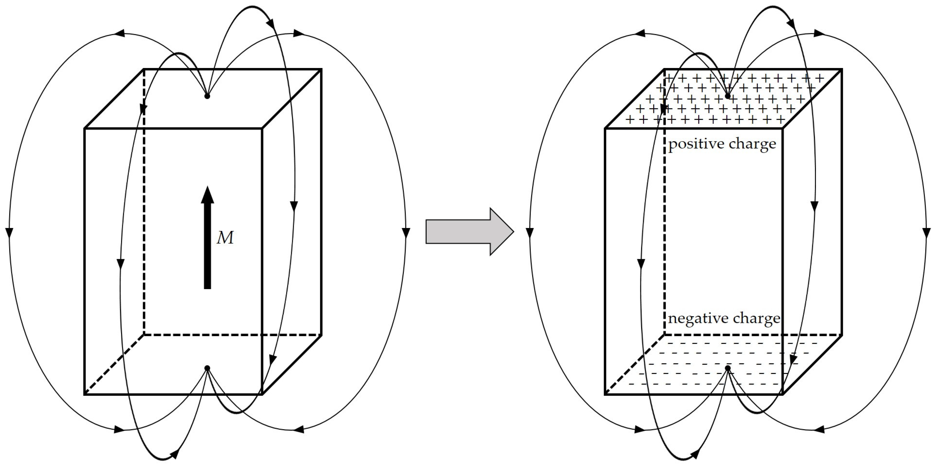
In VCM, the energized coil is forced by the Ampere force along the moving direction under a magnetic field perpendicular to the surface of the permanent magnets. Thus, the magnetic flux density z-component (Bz) distribution calculation is crucial for Ampere force computation. FEM and EMC method are used to calculate Bz. In FEM simulations by COMSOL Multiphysics 6.2 software, the side length of free tetrahedral mesh ranges from 0.16 mm to 0.8 mm. In the EMC model, the magnet is conceptualized as a distribution of equivalent “magnetic charges”, as shown in Figure 1. Specifically, for a rectangular bar magnet polarized along the z-direction, positive and negative magnetic charges are uniformly distributed on the top and bottom surfaces, respectively.
According to the EMC method in Ref. [16], the component Bz originating from the positive and negative magnetic charges can be expressed as follows:
B z + = B r 4 π arcsin ( x - a 2 ) ( y - b 2 ) ( x - a 2 ) 2 + z 2 ( y - b 2 ) 2 + z 2 - arcsin ( x - a 2 ) ( y + b 2 ) ( x - a 2 ) 2 + z 2 ( y + b 2 ) 2 + z 2 B r 4 π arcsin ( x + a 2 ) ( y - b 2 ) ( x + a 2 ) 2 + z 2 ( y - b 2 ) 2 + z 2 - arcsin ( x + a 2 ) ( y + b 2 ) ( x + a 2 ) 2 + z 2 ( y + b 2 ) 2 + z 2
B z - = B r 4 π arcsin ( x - a 2 ) ( y - b 2 ) ( x - a 2 ) 2 + ( z + h ) 2 ( y - b 2 ) 2 + ( z + h ) 2 - arcsin ( x - a 2 ) ( y + b 2 ) ( x - a 2 ) 2 + ( z + h ) 2 ( y + b 2 ) 2 + ( z + h ) 2 B r 4 π arcsin ( x + a 2 ) ( y - b 2 ) ( x + a 2 ) 2 + ( z + h ) 2 ( y - b 2 ) 2 + ( z + h ) 2 - arcsin ( x + a 2 ) ( y + b 2 ) ( x + a 2 ) 2 + ( z + h ) 2 ( y + b 2 ) 2 + ( z + h ) 2
B z   ( x ,   y ,   z ) = B z +   -   B z -
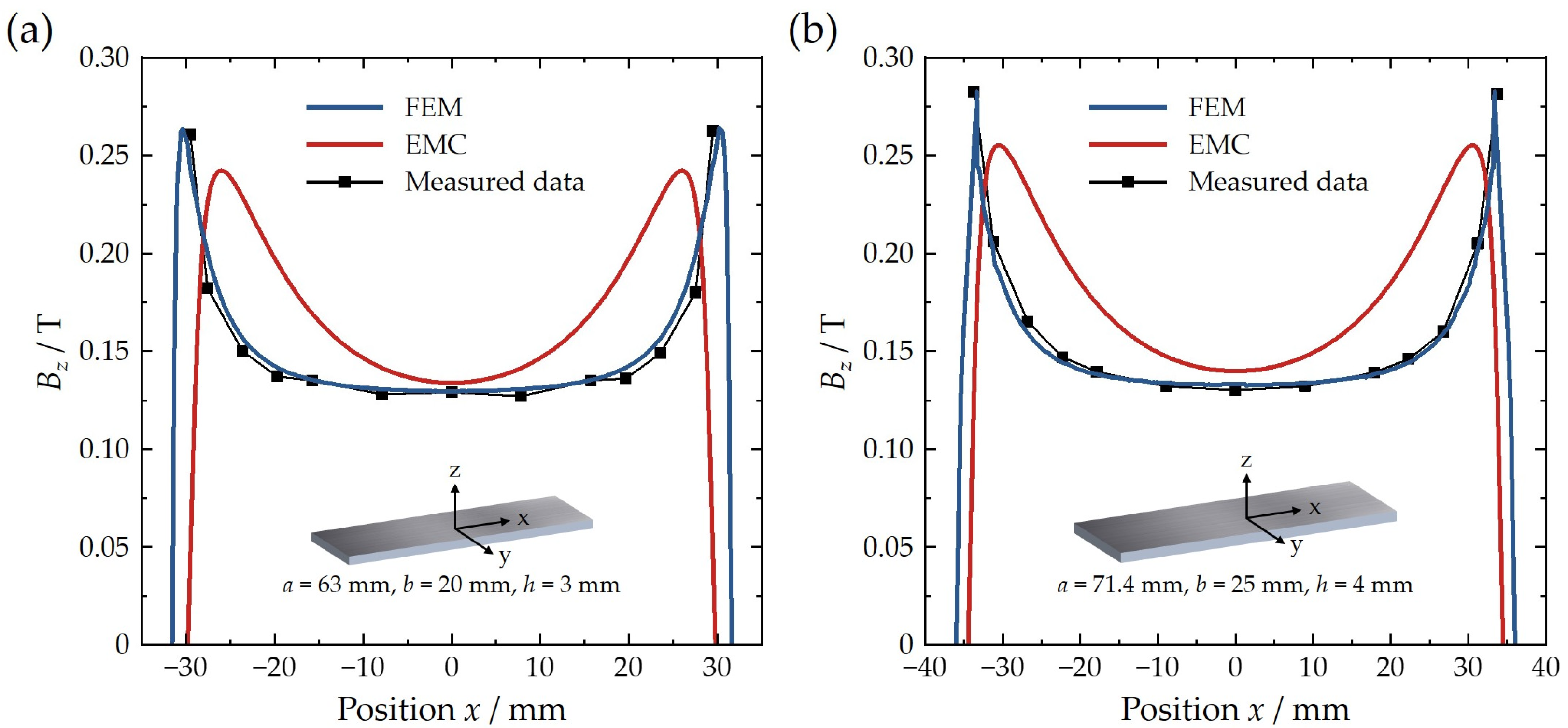
The total z-component of magnetic flux density can be determined through Equation (3). Figure 2 illustrates Bz distribution along x-direction position at a distance of 0.4 mm from the surface for two rectangular bar 45SH NdFeB permanent magnets (Senyang Co., Ltd., Ganzhou, China) (Magnet A (length a = 63 mm, width b = 20 mm and height h = 3 mm) and Magnet B (a = 71.4 mm, b = 25 mm, h = 4 mm)) with a residual magnetic flux density of 1.32 T [17]. The black dotted line represents the Bz profile measured by a Gauss meter, while the blue and red curves denote the FEM simulation and EMC calculation results, respectively.
Experimental results reveal distinct spatial characteristics: Bz distribution is flat with a relatively small value in the central region (spanning ~40 mm for Magnet A with 0.13 T and ~45 mm for Magnet B with 0.13 T). Bz gradually increases toward the edges, peaking at Bz = 0.265 T (Magnet A) and 0.28 T (Magnet B), located ~2 mm from the edge, and rapidly decays to zero at the extremities. Comparative analysis demonstrates that FEM simulations correspond closely with measured data, whereas EMC exhibits systematic deviations. Herein, EMC predicts a narrower central flat region with slightly elevated Bz values (~5.0%/7.7% overestimation for Magnet A/B), a peak intensity reduced to ~90% of the measured values, and a peak position shifted ~3 mm toward the center. Despite EMC’s high computational efficiency, its reduced accuracy in edge-field prediction highlights FEM’s superiority for high-fidelity modeling of magnets in VCMs.
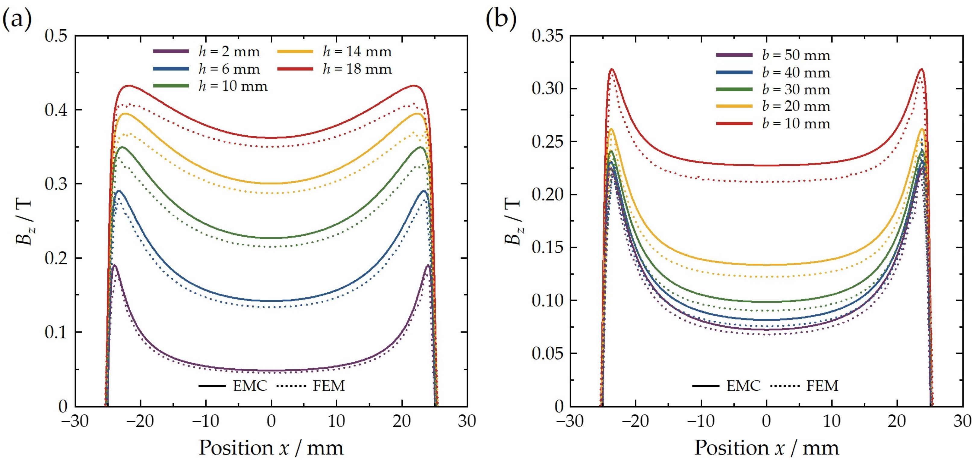
Figure 3 presents the Bz distribution along the x-axis at 0.4 mm height above the surface under different parameters for the magnet. Figure 3a depicts the variation of Bz distribution with position x, for magnets with dimensions a = b = 50 mm, as the height h varies from 2 mm to 18 mm. The solid and dashed lines represent EMC and FEM results, respectively. Although there is a certain deviation between the results obtained from the two methods, the overall trend is consistent. As h increases, the magnetic flux density gradually enhances, and the saddle between the flat region and the peak value position diminishes, indicating that a thicker magnet will strengthen the overall magnetic field. Figure 3b shows the variation of Bz with position x for magnets with a = 50 mm and h = 3 mm, as b varies from 10 mm to 50 mm. When b increases, the leakage of magnetic flux becomes more pronounced, resulting in a gradual decrease in Bz. The above analysis demonstrates that increasing the permanent magnet thickness while reducing its lateral dimensions will contribute to a significant enhancement in the z-component of the magnetic flux density (Bz) at the surface.

2.2. Analysis of Optimal Structural Parameters of VCM

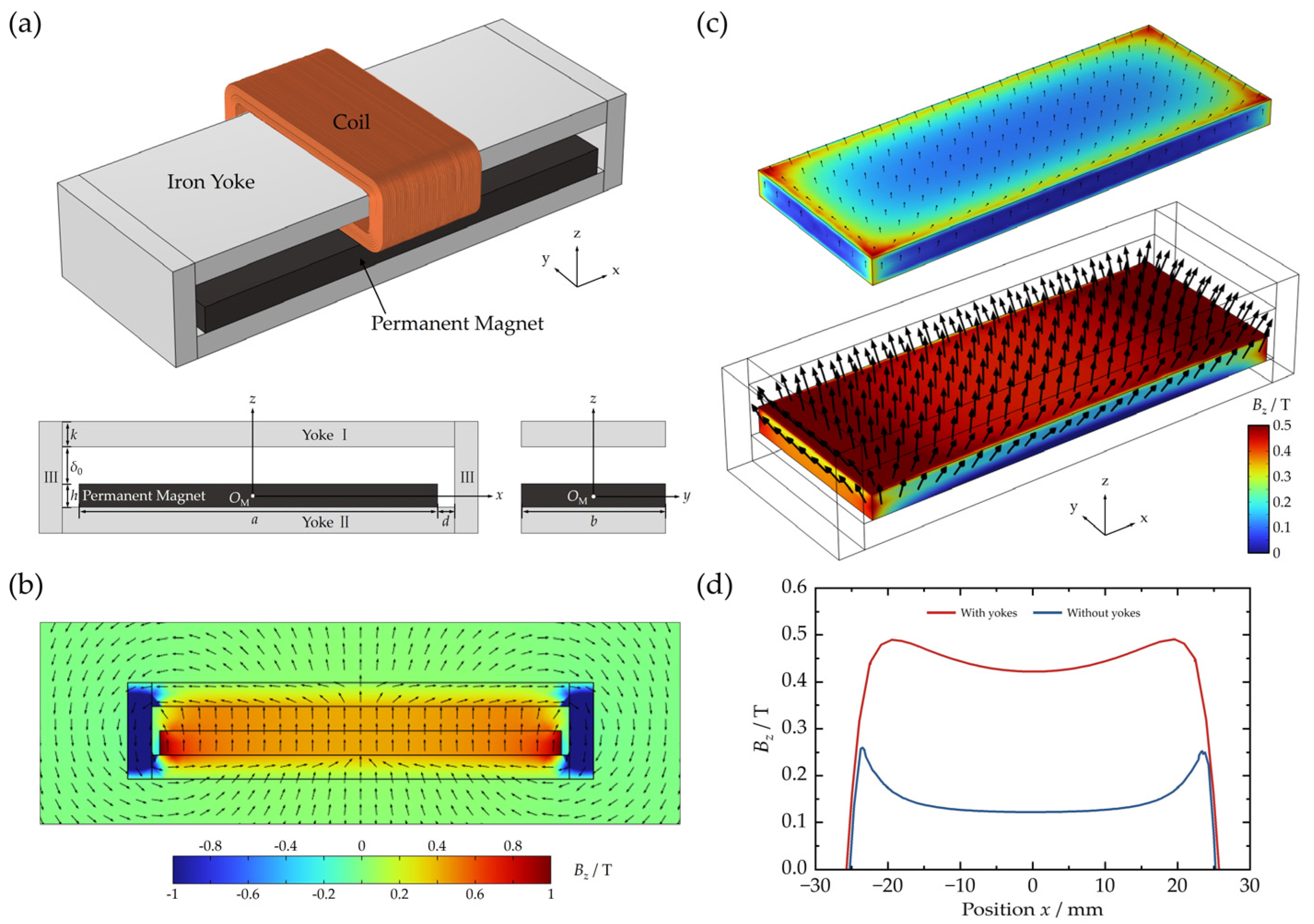
On the basis of analytical methods and magnetic field distribution characteristics for individual permanent magnets, the investigation of Bz distribution within the air gap of VCMs is extended. A simplified structural model of a moving-coil VCM is presented in Figure 4a, and in this model, both the permanent magnet and yokes adopt cuboidal configurations. The magnet is directly fixed atop yoke II, while yoke I covers the upper surface of the magnet, forming an air gap with a uniformly vertically upward magnetic field distribution. Yokes I and II strictly match the width of the magnet, while their lengths are slightly extended to optimize magnetic circuit closure. The lateral yokes III further complete the closed magnetic circuit, serving to enhance magnetic flux density and constrain uniform field distribution. Under this design, the energized coil experiences a unidirectional Ampere force within the air gap.
Figure 4b further illustrates the spatial distribution characteristics of Bz in the x-z plane of the VCM. FEM results indicate that the central air gap region exhibits a highly uniform vertically upward magnetic field (Bz = 0.42 T), while the lateral fields are constrained by the boundary conditions of yoke III, resulting in strictly orthogonal orientations to the yoke surfaces and forming gradient decay zones. This feature establishes the central air gap region as the primary effective working region of the motor. To quantify the yokes’ optimization effect on magnetic field, Figure 4c compares the Bz distributions via FEM between a single permanent magnet (geometric parameters: a = 50 mm, b = 20 mm, and h = 3 mm) and a yoke-integrated system (yoke length ay = 52 mm, yoke thickness k = 3 mm, and air gap δ0 = 3 mm). Figure 4d extracts the Bz profile along the air gap’s central x-axis, and results demonstrate that the yoke structure markedly enhances system performance: the average Bz value (Bz mean) increases from 0.14 T to 0.42 T (nearly 200% improvement), while the field uniformity index (Bz maxBz min)/Bz mean decreases from 70.2% to 14.3%, validating the yoke’s critical role in suppressing edge effects and optimizing magnetic circuit efficiency.
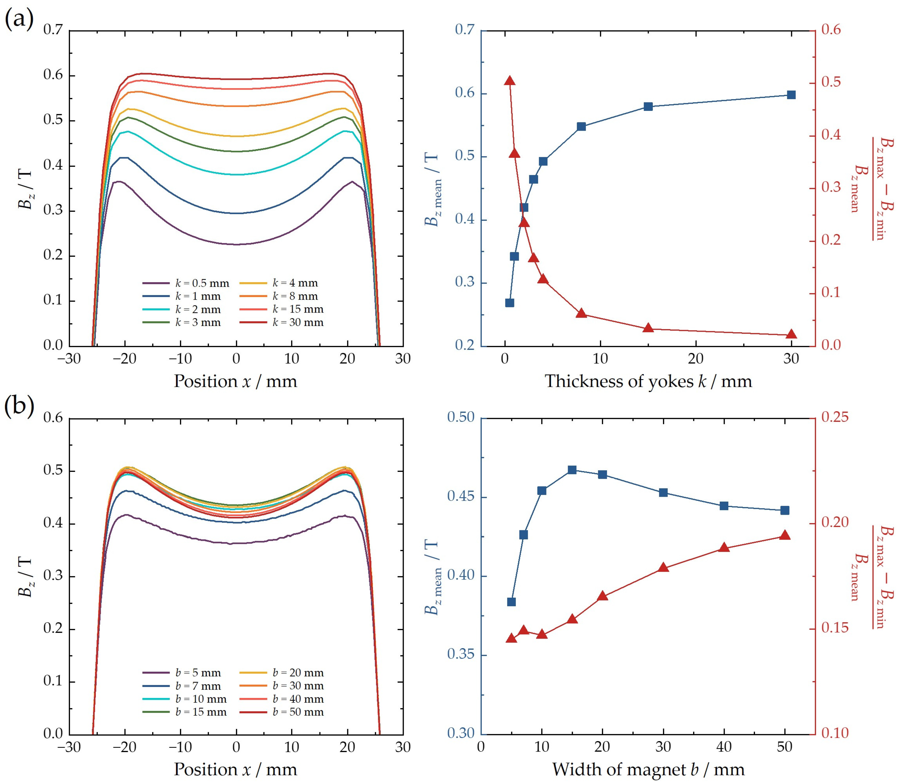
Furthermore, the influence of the structural parameters of VCM on the magnetic field distribution within the air gap is systematically analyzed. The magnet length is determined by the stroke of moving group and the dimensions of given coil, and other important parameters like magnet width and yoke thickness will be determined by FEM results. Figure 5a illustrates Bz distributions at the center line of the air gap under fixed VCM parameters (a = 50 mm, b = 20 mm, h = 3 mm, δ0 = 3 mm) with varying yoke thickness k. As k increases from 0.5 mm to 30 mm, the Bz mean in the central effective zone (80% working area) shows a monotonic growth trend, and (Bz maxBz min)/Bz mean decreases continuously. It is obvious that the thicker yokes will enhance the intensity and uniformity of the magnetic field in the air gap. Notably, when k ≥ 8 mm, Bz mean growth approaches saturation (<8.3% increment), indicating diminishing returns from further thickening yokes. The scatter chart on the right reveals that k = 3 mm corresponds to the inflection point for both Bz mean growth and flatness improvement, where yoke thickness equals magnet thickness (k = h), and this configuration achieves optimal volumetric efficiency, maintaining field intensity. Figure 5b shows Bz distributions for fixed parameters (a = 50 mm, k = h = δ0 = 3 mm) with varying magnet width b (5 ~ 50 mm). Experimental results demonstrate a complicated relationship between b and Bz mean: there is an increase in peak value at 0.47 T when b ≤ 30 mm, followed by a decay to 0.44 T due to intensified magnetic leakage. Meanwhile, (Bz maxBz min)/Bz mean increases monotonously with wider magnet, confirming that there is severe fringe flux leakage at excessive widths. Considering both field intensity and uniformity index, the recommended optimal magnet width ranges from 10 mm to 30 mm.
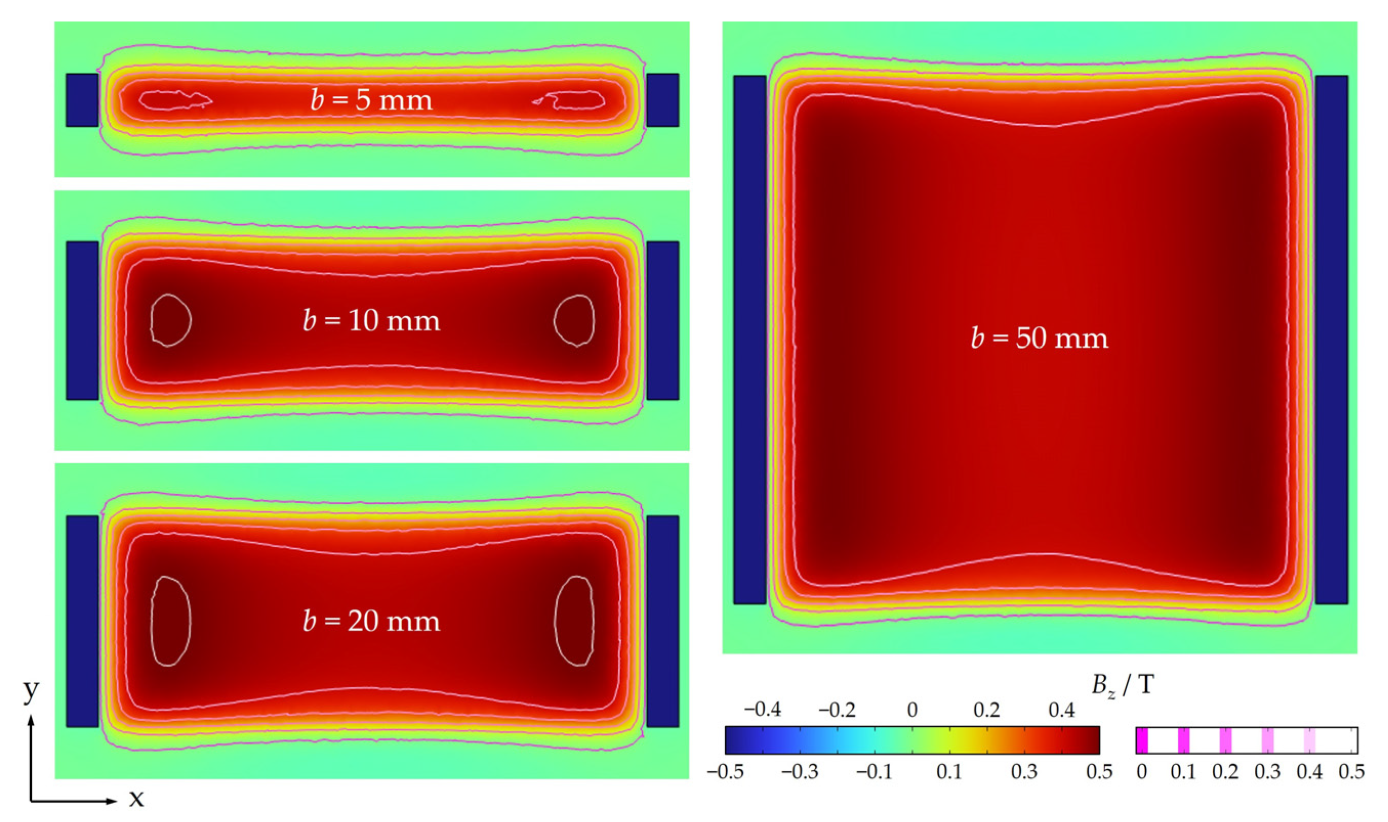
As shown in Figure 3b, the magnetic flux density Bz of a single permanent magnet exhibits monotonic attenuation with increasing width parameter b. However, in the VCM system where the coil moves along magnetic yoke I without yoke’s constraint in the y-direction, Bz demonstrates a non-monotonic variation characterized by initial enhancement, then followed by attenuation as b increases (see Figure 6). The 2D Bz distribution on the x-y plane results reveal that the contour spacing between Bz = 0 (external VCM region) and Bz = 0.4 T (edge zone in the air gap along the y-direction) remains consistently within about 5 mm across all b values. When b is small (b < 10 mm), the magnetic flux confinement effect of the yoke dominates, effectively suppressing edge flux leakage. As b increases to the 10–30 mm range, the magnetic field enhancement from the yoke progressively counteracts the flux leakage induced by width extension. Beyond the critical threshold of b = 30 mm, the flux leakage increment significantly exceeds the yoke’s confinement capacity, leading to a decline in overall magnetic field intensity. These analysis results provide theoretical guidance for the rapid preliminary determination of optimal geometric parameters under a specified magnet length.

2.3. Simplified Model Based on EMC Method

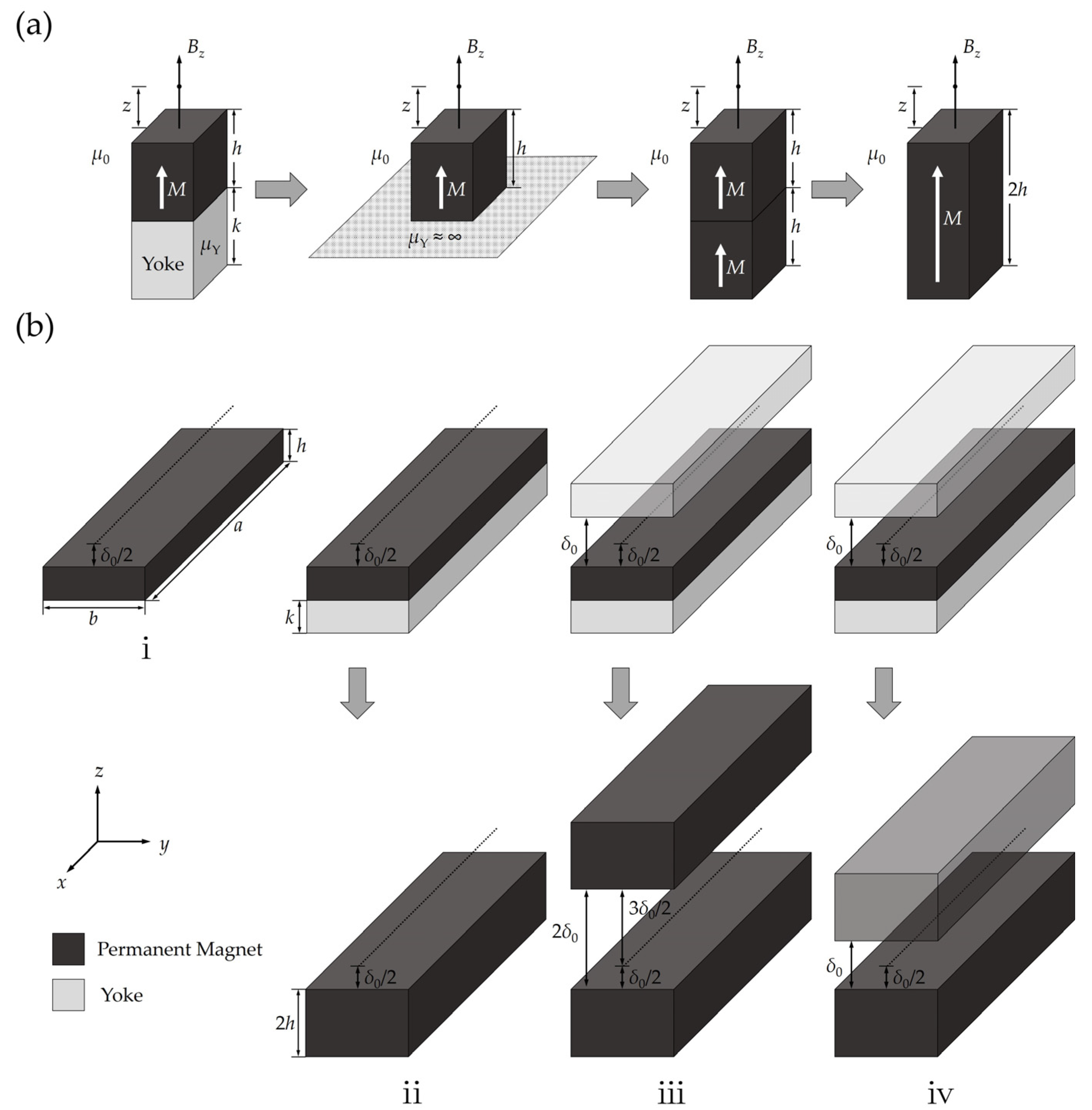
Compared with FEM, the EMC method demonstrates superior computational efficiency. Investigating the EMC theory for analyzing the magnetic flux density distribution in the air gap center of VCM holds significant importance for enhancing design efficiency. In EMC theory, when ferromagnetic material (i.e., magnetic yoke) exists behind the permanent magnet along its magnetization direction, as shown in Figure 7a, the yoke-magnet system can be equivalently modeled as a permanent magnet with doubled thickness through the method of images [18] while maintaining the original magnetization direction. Herein, the permeability of solid ferromagnetic material μY is far larger than the permeability of magnet and air, so it can be regarded that μY ≈ ∞.
Based on the image method, the Bz distribution within the air gap center for VCM is gradually deduced, as described in Figure 7b. For a single magnet (Case ⅰ) with thickness h, from Equation (3), the calculation formula for Bz at a distance δ0/2 from the surface can be expressed as
B z i = F ( h ,   δ 0 / 2 )
and the Bz calculation formula for equivalent magnet (Case ⅱ) with doubled thickness 2h should be modified from Equation (4) to Equation (5)
B z ii = F ( 2 h ,   δ 0 / 2 )
In Case ⅲ, when another magnetic yoke exists at a distance δ0 from the surface of the yoke-magnet structure, the yoke-magnet-air gap-yoke system can be equivalently modeled as two permanent magnets of 2h thickness with a separation of 2δ0 via the mirror image method. Consequently, Bz distribution at the air gap center is expressed as:
B z iii = F ( 2 h ,   δ 0 / 2 ) + F ( 2 h ,   3 δ 0 / 2 )
Similar to Case ⅲ, the yoke-magnet-air gap-yoke system in Case ⅳ can also be equivalently regarded as two magnets of 2h thickness with a separation of δ0, due to the magnetic yokes serving to form a closed magnetic circuit. In this condition, the Bz distribution can be expressed as
B z iv = 2 F ( 2 h ,   δ 0 / 2 )
Based on the above theoretical model, a comparative analysis of Bz distribution at the air gap center for VCM with six structural parameter combinations (length a = 50 mm, width b = 50/20 mm, thickness h = 2/3 mm, air gap δ0 = 2/3 mm) is conducted. As shown in Figure 8a–c, when a = b = 50 mm, the FEM simulation results significantly exceed those from EMC method. This discrepancy originates from modeling differences: FEM comprehensively characterizes both magnetic enhancement of the yoke and flux leakage induced by wide magnet, whereas EMC only approximates the yoke’s enhancement by doubling the equivalent magnet thickness, leading to underestimation of the yoke’s contribution. Notably, when b = 20 mm corresponding to optimal design range of VCM, EMC calculations show good agreement with FEM simulations (see Figure 8d–f). Specifically, FEM curves lie between the results of EMC (iii) and EMC (iv). Case iii underestimates magnetic enhancement by simplifying the top yoke as a mirror boundary without considering complete closed magnetic circuit formation, while Case iv overestimates the effect by equivalently treating the yoke as permanent magnet material. This comparison verifies that FEM more accurately characterizes the composite action mechanism of the yoke in practical magnetic circuits, with simulation results effectively reflecting the equilibrium between magnetic enhancement and leakage effects. Thus, a simple calculation method is proposed, combining EMC (iii) and EMC (iv) for rapid and accurate determination of Bz distribution in the VCM air gap. The mathematical formulation is defined as the arithmetic mean of two cases:
B z = ( B z iii + B z iv ) / 2 = 3 2 F ( 2 h ,   δ 0 / 2 ) + 1 2 F ( 2 h ,   3 δ 0 / 2 )
where EMC (iii) represents a conservative estimation model neglecting complete magnetic circuit closure, and EMC (iv) denotes an upper-bound model with overcompensated yoke enhancement effects. This simple calculation method maintains the computational efficiency of the EMC method while correcting the over/underestimation deviations inherent in individual models regarding yoke effects.

3. Performance Evaluation for Rapid Zoom Lens with VCM

As described above, these results confirm that the systematic design process of optimal structural parameters for VCM is determined in ideal conditions. In this section, a VCM has been designed for a certain rapid zoom lens with cost and space limitations. Figure 9a presents the schematic of a 40× rapid zoom lens with a focal length range of 7.5–300 mm. In this optical system, two zoom groups are driven by different VCMs, as shown in Figure 9b. As an example, the VCM with a larger stroke is analyzed. The load (weight ml = 40.8 g), including zoom group and copper coil, is driven by VCM in S-curve trajectory [4] with a stroke of 35.4 mm. For the rapid zoom lens, zoom time should be controlled within 0.2 s, and the corresponding demand acceleration al is larger than 16 m/s2. Considering the actual using posture where the lens may be positioned vertically downward, the zoom group should be driven against the force of gravity. Thus, the demand driving force Fd for VCM should be satisfied: Fdml (al + g), i.e., Fd ≥ 1.06 N.
The permanent magnet length am = 49 mm is based on the displacement requirements of stroke and coil size, while the thickness h = 3 mm is selected considering cost constraints. The yoke length ay = 51 mm is slightly longer than am. Following the inflection point condition (kh) for both magnetic flux density growth and flatness improvement, the yoke thickness k is set as k = 2.5 mm. Considering the gap between coil and yoke, air gap δ0 is determined as δ0 = 2.8 mm, which is slightly larger than the coil thickness (2 mm). Parametric sweep analysis of magnet width b under am = 50 mm revealed that the recommended optimal b ranges from 10 mm to 30 mm, and b = 20 mm yields relatively large magnetic flux density in the air-gap central region.
For the VCM with these structural parameters, FEM and simplified EMC model are used to calculate axial Bz distribution in the working air gap region (white dashed line), as illustrated in Figure 9c. Through EMC calculations (blue curve) and FEM simulation (red curve) results, average Bz value is about 0.45 T within the effective stroke. Goodness-of-fit R2 for the two results exceeds 0.98, confirming the accuracy of the proposed simplified EMC model with high computational efficiency. The copper coil is modelled as stranded with total turns N = 400 and resistivity ρ e = 1.678  ×  10 - 8   Ω · m . The VCM operates under U = 12 V DC power supply with current I = 1.55 A, and the axial driving force is calculated according to the Ampere force law: Fdrive = NBzIle = NBzIb = 5.58 N, where le = b indicates effective length in the magnetic field. Driving force Fdrive = 5.58 N for the designed VCM is nearly 5 times the demand force Fd = 1.06 N. Similarly, the structural design of VCM for another zoom group can be finalized in the same method. So far, the systematic design of optimal structural parameters for VCMs has been achieved for a certain rapid zoom lens.
Building upon the optimized VCM driving architecture, prototype fabrication and optical alignment of the rapid zoom lens are successfully accomplished. Figure 10a shows the actual trajectory including four turns of a moving group, which is driven by VCM and controlled in linear motion with a stroke of 35.4 mm. It costs about 0.18 s for the moving group to reach the destination during a trip, and rapid zoom is characterized by corresponding optical performance experiments in Figure 10b. At t = 0 s, the rapid zoom lens operates in short-focus state, providing wide-angle surveillance covering multiple targets across two buildings and parking areas. After transition to long-focus state at t = 0.2 s, the system successfully captures a high-resolution image of the white vehicle, corresponding to the central marked red frame in short-focus state. Experimental results confirm that the rapid zoom system achieves a 100-ms-level smooth transition between global scene perception (short-focus state) and local feature identification (long-focus state). This rapid-response dual-modal cooperative operation characteristic effectively satisfies stringent requirements for dynamic imaging systems in applications including security surveillance (target detection-identity recognition), industrial visual inspection (defect localization-microscopic analysis), and intelligent logistics management (area scanning-barcode reading).

4. Conclusions

In conclusion, this study systematically analyzes the structural design of the voice coil motor for high-magnification rapid zoom optical systems through numerical computations of magnetic field distributions. From the single permanent magnet, FEM simulation results correspond to Gauss meter experimental results. Both FEM and EMC results confirm that increasing the permanent magnet thickness while reducing its lateral dimensions will contribute to a significant enhancement in magnetic flux density. Furthermore, the influence of structural parameters like magnet width and yoke thickness of a simplified moving-coil VCM is analyzed, validating the yoke’s critical role in suppressing edge effects and optimizing magnetic circuit efficiency. For fixed VCM parameters (a = 50 mm, b = 20 mm, h = 3 mm, δ0 = 3 mm), k = 3 mm corresponds to the inflection point for both flux density growth and flatness improvement, where k = h configuration achieves optimal volumetric efficiency, maintaining field intensity. For VCM (a = 50 mm, k = h = δ0 = 3 mm), the recommended optimal magnet width b ranges from 10 mm to 30 mm, considering both the magnetic flux confinement effect of yokes and edge flux leakage of wider magnet. Moreover, a simple EMC calculation method is proposed for rapid and accurate determination of the Bz distribution in the VCM air gap. Based on systematic magnetic field analysis in ideal conditions, optimal structural parameters for VCM are determined for a 40× rapid zoom lens with cost and space limitations. The VCM with a larger stroke is analyzed, and driving force Fdrive = 5.58 N for the designed VCM is nearly 5 times the demand force Fd = 1.06 N. Prototype fabrication and optical alignment of the rapid zoom lens are successfully accomplished, building upon the optimized VCM driving architecture. The actual trajectory shows that it costs about 0.18 s for the moving group to reach the destination during a 35.4 mm trip, and experimental photographs confirm that the rapid zoom system achieves 100-ms-level smooth transition between global scene perception (short-focus state) and local feature identification (long-focus state). This rapid zoom optical system shows great potential in applications including security surveillance, industrial visual inspection, and intelligent logistics management.
Author Contributions

Conceptualization, J.G.; formal analysis, J.G.; investigation, J.G.; methodology, J.G.; software, J.G.; supervision, J.L.; validation, J.G.; writing—original draft, J.G.; writing—review and editing, D.L. and J.L. All authors have read and agreed to the published version of the manuscript.

Funding

This research received no external funding.

Institutional Review Board Statement

Not applicable.

Informed Consent Statement

Not applicable.

Data Availability Statement

The raw data supporting the conclusions of this article will be made available by the authors upon request.

Acknowledgments

We thank Union Optech Co., Ltd. for their support.

Conflicts of Interest

Author Junqiang Gong was employed by the company Union Optech Co., Ltd. The remaining authors declare that this research was conducted in the absence of any commercial or financial relationships that could be construed as a potential conflict of interest.

References

  1. Liu, Y.; Yang, B.; Gu, P.; Wang, X.; Zong, H. 50× five-group inner-focus zoom lens design with focus tunable lens using Gaussian brackets and lens modules. Opt. Exp. 2020, 28, 29098–29111. [Google Scholar] [CrossRef] [PubMed]
  2. Jiang, Z.; Wang, D.; Zheng, Y.; Liu, C.; Wang, Q. Continuous optical zoom microscopy imaging system based on liquid lenses. Opt. Exp. 2021, 29, 20322–20335. [Google Scholar] [CrossRef] [PubMed]
  3. Zou, Y.; Chau, F.S.; Zhou, G. Ultra-compact optical zoom endoscope using solid tunable lenses. Opt. Exp. 2017, 25, 20675–20688. [Google Scholar] [CrossRef] [PubMed]
  4. Gong, J.; Luo, J. Rapid and Precise Zoom Lens Design Based on Voice Coil Motors with Tunnel Magnetoresistance Sensors. Appl. Sci. 2024, 14, 6990. [Google Scholar] [CrossRef]
  5. Gong, J.; Liu, D.; Luo, J. A Positioning System Design Based on Tunnel Magnetoresistance Sensors for Rapid Zoom Optical Lens. Sensors 2025, 25, 1820. [Google Scholar] [CrossRef] [PubMed]
  6. Li, H.; Chen, H.; Chen, J.; Zhang, Y.; Piao, Y. Study on pressure angle optimization for cam curve of continuous zoom system based on the particle swarm optimization. Opt. Rev. 2024, 31, 1–7. [Google Scholar] [CrossRef]
  7. Zhou, P.; Yu, Y.; Li, F.; Ye, X. An infrared zoom imaging system with large zoom ratio based on linear motion mechanism. J. Infrared Millim. W. 2023, 42, 845–852. [Google Scholar] [CrossRef]
  8. Wang, Y.; Chen, Z.; Shi, Y.; Cui, C.; Cheng, F. Longitudinal Composite-Mode Linear Ultrasonic Motor for Motion Servo System of Probe Station. Actuators 2020, 9, 111. [Google Scholar] [CrossRef]
  9. Liu, C.; Lin, P. A miniaturized low-power VCM actuator for auto-focusing applications. Opt. Exp. 2008, 16, 2533–2540. [Google Scholar] [CrossRef] [PubMed]
  10. Hsieh, C.; Liu, C. Design of a voice coil motor actuator with L-Shape coils for optical zooming smartphone cameras. IEEE Access 2020, 8, 20884–20891. [Google Scholar] [CrossRef]
  11. Li, L.; Pan, D.; Tang, Y.; Wang, T. Analysis of flat voice coil motor for precision positioning system. In Proceedings of the 2011 International Conference on Electrical Machines and Systems, Beijing, China, 20–23 August 2011. [Google Scholar] [CrossRef]
  12. Luo, C.; Sun, J.; Wang, X.; Shen, Q. Design of voice coil motor with the forward winding for linear vibro-impact systems. IEEE Trans. Magn. 2017, 53, 8107509. [Google Scholar] [CrossRef]
  13. Zhang, Z.; Luo, M.; Zhou, H.; Duan, J. Design and analysis of a novel two-degree-of-freedom voice coil motor. IEEE-ASME Trans. Mechatron. 2019, 24, 2908–2918. [Google Scholar] [CrossRef]
  14. Kang, S.; Jeong, Y.; Choi, Y. Design of a finger-sized voice coil motor for high-speed scanners. Int. J. Precis. Eng. Man. 2023, 24, 209–217. [Google Scholar] [CrossRef]
  15. Jiang, Z.; Park, K.; Hwang, S. Novel Magnetic Circuit Design and Acceleration Calculation of Horizontal Linear Vibration Motor. Actuators 2022, 11, 149. [Google Scholar] [CrossRef]
  16. Li, J.; Zheng, Q.; Song, Y.; Liu, J. Computation of the Magnetic Field of Permanent Magnet with Equivlent Magnetic Charge Method. J. Yunnan Norm. Univ. 1999, 19, 33–36. [Google Scholar]
  17. Dang, Z.; Qahouq, J.A.A. Permanent magnet toroid power inductor with increased saturation current. In Proceedings of the 2013 Twenty-Eighth Annual IEEE Applied Power Electronics Conference and Exposition (APEC), Long Beach, CA, USA, 17–21 March 2013. [Google Scholar] [CrossRef]
  18. Furlani, E.P. Permanent Magnet and Electromechanical Devices: Materials, Analysis, and Applications; Academic Press: New York, NY, USA, 2001; pp. 185–190. [Google Scholar] [CrossRef]
Figure 1. Schematic for the EMC method.
Actuators 14 00332 g001
Figure 2. Measured data, FEM and EMC results of Bz distribution along x-direction position for (a) Magnet A and (b) Magnet B.
Actuators 14 00332 g002
Figure 3. FEM and EMC results of Bz distribution along x-direction position for permanent magnets for (a) fixed b = 50 mm with varying height h and (b) fixed h = 3 mm with varying width b.
Actuators 14 00332 g003
Figure 4. (a) Schematic of a simplified structural model of a moving-coil VCM. (b) FEM result of Bz distribution in the x-z plane of the VCM. (c) FEM result of Bz distribution between single permanent magnet and yoke-magnet system. (d) FEM results of Bz profile along the air gap’s central x-axis for magnet and yoke-magnet system.
Actuators 14 00332 g004
Figure 5. FEM results of Bz distribution along the air gap’s central x-axis for VCMs with (a) varying yoke thickness k and (b) varying width b.
Actuators 14 00332 g005
Figure 6. FEM results of Bz distribution in x-y plane of VCM air gap center with varying b.
Actuators 14 00332 g006
Figure 7. (a) Schematic for the method of images. (b) Schematics for Case i, ii, iii and iv.
Actuators 14 00332 g007
Figure 8. FEM, EMC (iii) and EMC (iv) results of Bz distribution along x-direction position at the air gap center for VCM with six structural parameter combinations. (a) a = 50 mm, b = 50 mm, h = 2 mm, δ0 = 3 mm. (b) a = 50 mm, b = 50 mm, h = 3 mm, δ0 = 3 mm. (c) a = 50 mm, b = 50 mm, h = 3 mm, δ0 = 2 mm. (d) a = 50 mm, b = 20 mm, h = 2 mm, δ0 = 3 mm. (e) a = 50 mm, b = 20 mm, h = 3 mm, δ0 = 3 mm. (f) a = 50 mm, b = 20 mm, h = 3 mm, δ0 = 2 mm.
Actuators 14 00332 g008
Figure 9. (a) Schematic for the rapid zoom lens. (b) Optical system and two VCMs of a rapid zoom lens. (c) FEM result of Bz distribution in x-z plane of the VCM; FEM and simplified EMC model results of Bz distribution along air gap’s central x-axis.
Actuators 14 00332 g009
Figure 10. Control the performance of the moving group and photographs captured by a rapid zoom optical system. (a) Actual and reference trajectories of a moving zoom group. (b) Photographs captured by a 40× rapid zoom lens with VCMs.
Actuators 14 00332 g010
Disclaimer/Publisher’s Note: The statements, opinions and data contained in all publications are solely those of the individual author(s) and contributor(s) and not of MDPI and/or the editor(s). MDPI and/or the editor(s) disclaim responsibility for any injury to people or property resulting from any ideas, methods, instructions or products referred to in the content.