Article

Investigation of Hysteresis Phenomena and Compensation in Piezoelectric Stacks for Active Rotor

1
National Key Laboratory of Helicopter Aeromechanics, Nanjing University of Aeronautics and Astronautics, Nanjing 210016, China
2
College of General Aviation and Flight, Nanjing University of Aeronautics and Astronautics, Nanjing 210016, China
*
Author to whom correspondence should be addressed.
Actuators 2025, 14(7), 327; https://doi.org/10.3390/act14070327
Submission received: 17 May 2025 / Revised: 24 June 2025 / Accepted: 25 June 2025 / Published: 1 July 2025
(This article belongs to the Section Aerospace Actuators)

Abstract

An active rotor with trailing edge flaps (TEFs) is an effective method for helicopter vibration elimination. The nonlinear hysteresis of piezoelectric actuators used to drive TEFs can adversely affect helicopter vibration control performance. In this paper, a hysteresis modeling and compensation study is performed for piezoelectric actuators used in TEFs. Firstly, the hysteresis characteristics of a rhombic frame actuator with input voltages at different frequencies are investigated by bench-top tests. Subsequently, the Bouc–Wen model is adopted to establish the hysteresis model of the piezoelectric actuator, with its parameters identified through the particle swarm optimization (PSO) algorithm. Experimental results demonstrate that the proposed model is capable of accurately capturing the hysteresis phenomenon of the piezoelectric actuator within the frequency range of 10–60 Hz. Finally, a compound control regime is established by integrating inverse Bouc–Wen model control with fuzzy PID feedback control. The experimental results indicate that the developed compound control regime can significantly suppress the piezoelectric actuator hysteresis of TEFs within the frequency bandwidth of 10–60 Hz, which lays the foundation for improving the vibration control performance of the active rotor with TEFs in the future.

1. Introduction

Modern helicopters are suffering from severe vibratory loads [1]. The high-level vibrations of a helicopter result in passenger and crew discomfort, a reduced fatigue life of structural components, the degraded reliability of onboard equipment, and increased maintenance costs [2]. The main source of these vibrations for a helicopter is the rotor operating in an unsteady aerodynamic environment. An active rotor with TEFs can modify the aeroelastic response and aerodynamic load distribution by the dynamic deflection of TEFs, thereby effectively reducing the vibratory loads of the helicopter rotor. Compared with passive vibration isolators and absorbers, an active rotor with TEFs offers adaptability to varying flight conditions with a minimal weight penalty [3,4], making it become a focus of helicopter rotor research.
Piezoelectric actuators are fundamental components of an active rotor system with TEFs. They have been applied in the aviation field due to unique properties including lightweight, compactness, wide operating bandwidth, and high energy density. However, the piezoelectric actuators used in TEFs still present unresolved challenges, such as the lack of accuracy due to the hysteresis in piezoelectric materials. Hysteresis is a form of nonlinearity with memory. The piezoelectric expansion depends not only on the current voltage excitation but also on the historical excitation profile. The nonlinearity of the system increases the difficulty of the modeling and compensation for hysteresis in piezoelectric materials [5]. Unmodeled hysteresis in the piezoelectric actuator can lead to inaccuracy in open-loop control and probably even the loss of stability in closed-loop control [6,7]. Therefore, many studies have been conducted on the hysteresis modeling for the TEF actuators. Andrew et al. [8] established a compensator based on an offline identification of a Krasnoselskii–Pokrovskii hysteresis operator, which is cascaded with the mechanism-actuated TEFs attached to a scaled helicopter rotor blade. Viswamurthy et al. [9,10,11] utilized the classical Preisach model to characterize the hysteresis of the TEF actuators and analyzed the influence of actuator hysteresis on the vibration control performance. Simulation results demonstrated that actuator hysteresis can impair the control law of TEFs and even increase the vibration loads of the helicopter rotor. Eric et al. [12,13] developed a hysteresis model based on the classic Preisach model using experimental data to assess the importance of actuator hysteresis on vibration and noise reduction in an active rotor with TEFs. This model was incorporated into the Active Vibration and Noise Reduction (AVINOR) code, and comprehensive simulation results demonstrated that the incorporation of hysteresis does not cause significant performance degradation in vibration suppression but can degrade the performance of noise reduction. Ganguli et al. [14] compensated the actuator hysteresis using an approximate inverse of the Preisach operator. Numerical results highlighted the critical influence of the hysteresis phenomenon on helicopter vibration control performance. The aforementioned studies demonstrated the importance of actuator hysteresis in the vibration/noise control of active rotors with TEFs. Nevertheless, most of them are limited to numerical simulation, with a notable scarcity of research on hysteresis suppression for the actuators used to drive TEFs. Meanwhile, the Krasnoselskii–Pokrovski model and classical Preisach model used in these references are computationally intensive and difficult to simulate hysteresis in TEFs with multiple frequency inputs. Therefore, it is imperative to develop a simple and practical hysteresis model that can be integrated into real-time control units for the active rotor with TEFs.
Over the past several decades, a lot of hysteresis models have been developed for piezoelectric actuators. According to whether input frequency is considered or not, hysteresis models can be classified into rate-independent hysteresis models and rate-dependent hysteresis models [15]. There are classical rate-independent hysteresis models, such as the Prandtl–Ishlinskii model, the Preisach model, and the Maxwell model. These models focus on mapping the nonlinear relationship between the input voltage and the output displacement at low frequencies. Rate-dependent hysteresis models, including the Bouc–Wen model, Dahl model, Backlash-like model, Duhem model, and a phenomenological model for rate-dependent hysteresis, are used to characterize the relationships among the input voltage, input frequency, and output displacement in piezoelectric actuators [16]. Compared with alternative rate-dependent models, the Bouc–Wen model has gained predominant adoption in hysteresis compensation due to its outstanding advantage of concision in both the model structure and identification process [17]. The Bouc–Wen model has been successfully applied in different mechanical applications. Zhang et al. [18] proposed a modified Bouc–Wen model to suppress the tendon-sheath mechanisms, which showed a good performance in compensating for the hysteresis of the tendon-sheath mechanism system. Yu et al. [19] developed a hybrid control based on an inverse Bouc–Wen model and PID feedback control for a piezo-actuated compliant mechanism, and experimental results demonstrated that better tracking performance can be achieved using this improved Bouc–Wen model. Zhang et al. [20] built a dynamic model of the soft pneumatic gripper (SPG) by combining the Bouc–Wen model with a linear dynamic model. Simulation results illustrated that the hysteresis inverse compensation control is effective for the SPG. Li et al. [21] developed a compensator by integrating an improved Q-learning algorithm with the Bouc–Wen feedforward control, which showed good performance in the hysteresis compensation of a macro-fiber composite bimorph. These studies show that the Bouc–Wen model exhibits superior performance in the hysteresis suppression of piezoelectric actuators, and thus, it deserves to be studied in the active rotor.
This study proposed a compound control regime by integrating an inverse model with fuzzy PID. Compared with previous studies, the established model achieves superior accuracy in capturing the hysteresis phenomenon of piezoelectric materials under multi-frequency control inputs. Moreover, the integrated fuzzy PID control endows the developed model with significantly enhanced adaptability, optimized parameter tuning capability, and superior robustness [22,23]. The proposed compound method provides a more effective way to compensate for the hysteresis in the piezoelectric actuators of TEFs used in the helicopter active rotor. This approach offers technical support in the design and vibration control of an active rotor with TEFs. On the basis of bench-top tests, a study on hysteresis compensation for piezoelectric actuators is conducted. Firstly, the hysteresis behavior of the rhombic frame actuator applied in driving TEFs is experimentally measured. Subsequently, based on the hysteresis characteristics of the actuator, the Bouc–Wen model is used to characterize the hysteresis of the actuator, and the PSO algorithm is adopted to identify the parameters of the model. Finally, a compound control regime combining an inverse Bouc–Wen model feedforward control and fuzzy PID is developed. Experimental results show that the hysteresis of the actuator at different frequencies from 10 Hz to 60 Hz is significantly suppressed.

2. Hysteresis Behaviors of a Piezoelectric Actuator

A piezoelectric actuator used to drive TEFs is composed of piezoelectric stacks and a displacement amplification mechanism. Piezoelectric materials exhibit several advantages, such as a wide operating bandwidth, fast dynamic response, and large output force. However, due to their small output displacement, it is necessary to design a displacement amplification mechanism to amplify the output displacement of piezoelectric materials. Typical displacement amplification mechanisms include the X-shaped displacement amplification mechanism, the L-shaped displacement amplification mechanism, the diamond-shaped displacement amplification mechanism, and the rhombic frame displacement amplification mechanism. Compared with others, the rhombic frame displacement amplification mechanism exhibits the advantages of zero mechanical backlash, structural simplicity, and high reliability. Consequently, the rhombic frame displacement amplification mechanism is adopted in many piezoelectric stack actuators for TEFs.
A 2 m radius, two-bladed active rotor with TEFs was designed to study the vibration control effect, as presented in Figure 1, and the detailed structure of the drive system is shown in Figure 2. The fundamental frequency of this active rotor is 15 Hz (900 r/min). According to the load transfer law of the rotor hub, vibration loads exerted by the blade on the hub can be transmitted to the fuselage through the rotor hub at harmonic frequencies of n N b Ω and ( n N b ± 1 ) Ω , where n is a positive integer, N b is the number of blades, and Ω is the rotor rotation frequency. Therefore, for a two-bladed rotor, the control frequency of TEFs is set to 1 Ω , 2 Ω , and 3 Ω , and the maximum drive frequency of the TEFs is 45 Hz.
According to the actuation requirements of an active rotor with TEFs, a piezoelectric stack actuator with a rhombic frame displacement amplification mechanism of TEFs was designed, as depicted in Figure 3, which is mainly composed of a rhombic frame and piezoelectric stacks. The short-axis direction of the actuator is fixed at one end, and the other end is connected to the load for output. The parameters of the rhombic frame actuator and the piezoelectric stack information are shown in Table 1 and Table 2. The output displacement of the piezoelectric stack is amplified by the displacement amplification mechanism based on the triangular amplification principle. The voltage-driven deformation of the piezoelectric stacks induces coupled long-axis expansion and short-axis compression in the rhombic frame displacement amplification mechanism. The bidirectional push/pull output of the rhombic frame actuator is achieved through exerting a bias voltage.
The hysteresis behavior of the rhombic frame piezoelectric actuator was studied using the experimental setup illustrated in Figure 4, where the bias voltage of the input signal was set to 50 V and the amplitude to 50 V (zero-peak). The control input signals of low voltage are generated by the controller (CompactRIO9049, National Instruments, Austin, TX, USA), and then amplified through a power amplifier (LA75C, Cedrat Technologies, Meylan, France) to amplify its voltage and current. A laser displacement sensor (HL-G103-A-C5, Panasonic, Kadoma-shi, Japan, positioning accuracy of ± 4   μm , resolution of 0.5   μm ) is used to measure the displacement of the actuator, and the displacement of the actuator is acquired through the real-time controller. Additional system delays can be avoided due to the synchronized acquisition of control input signals and actuator displacement signals.
The hysteresis behavior of rhombic frame actuators is mainly determined by the nonlinear hysteresis of the piezoelectric stack and the dynamic characteristics of the actuator. In order to investigate the hysteresis characteristics of the actuator at different input frequencies, actuation signals with different frequencies were applied to the actuator. The hysteresis curves of the rhombic frame actuator at different frequencies are shown in Figure 5 and Figure 6. As evidenced by Figure 5, under low-frequency actuation voltage, the hysteresis curves of the actuator with different actuation frequencies almost coincide, indicating that the hysteresis characteristics of the actuator at low frequencies are predominantly determined by the hysteresis characteristics of the piezoelectric materials. Figure 6 reveals that under high-frequency actuation voltage, the hysteresis curves of the actuator vary significantly at different frequencies. This implies that the hysteresis characteristics of the actuator at high frequencies are governed not only by the intrinsic hysteresis characteristics of the piezoelectric materials but are also substantially influenced by the dynamic characteristics determined by the mass, damping, and stiffness of the actuator.

3. Hysteresis Model of Piezoelectric Actuator
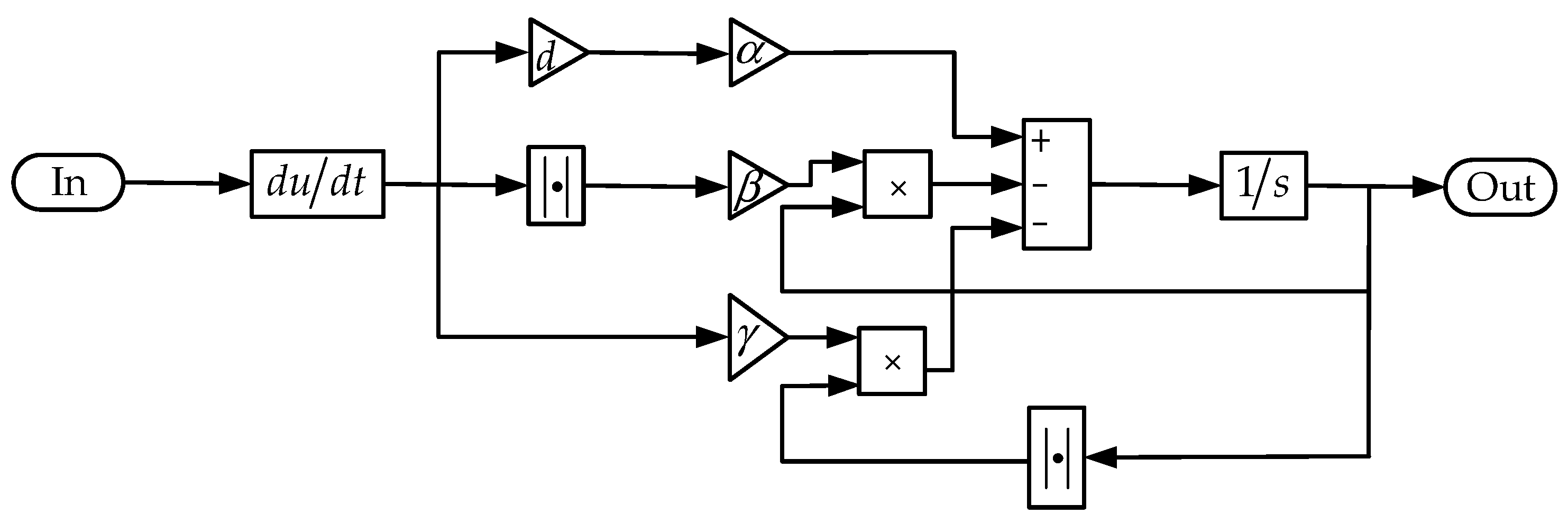
3.1. Bouc–Wen Model

The Bouc–Wen model was adopted to establish the hysteresis model of the piezoelectric actuators used to drive TEFs. The Bouc–Wen model is given by
  h ˙ = α d u ˙ β u ˙ h h n 1 γ u ˙ h n
where h is used to characterize the input–output hysteresis curve of the actuator, α , β and γ determine the shape of the hysteresis curves, d is the equivalent piezoelectric coefficient, u is the actuation voltage, and n is the order of the model. To improve the computational efficiency of the model, n was set to 1 in this study. Equation (1) can be simplified as
  h ˙ = α d u ˙ β u ˙ h γ u ˙ h
Based on Equation (2), h is expressed as a block diagram shown in Figure 7. The TEF deflection is driven by the actuator, so the dynamic deflection performance of the TEFs is influenced by the mass and damping characteristics of the actuator. Considering mass, damping, and stiffness characteristics, the motion equation of the rhombic frame piezoelectric actuator is expressed as
m x ¨ + b x ˙ + kx = k ( du h )
where m is the equivalent mass of the actuator, b is damping, k is stiffness, and x is output displacement.
According to the motion equation of the actuator, the input–output hysteresis model of the actuator can be represented as seen in Figure 8. As can be seen from this figure, the rate-dependent hysteresis model of the actuator consists of the Bouc–Wen model and the second-order transfer function. The Bouc–Wen model is used to depict the hysteresis caused by the piezoelectric materials. The second-order transfer function is applied to describe the influence of dynamic characteristics, including mass, damping, and stiffness, on the output response of the actuator.

3.2. Parameter Identification of Bouc–Wen Model

The developed actuator hysteresis model includes four parameters d , α , β , γ of the Bouc–Wen model and three parameters m , b , k of the second-order transfer function. The natural frequency of the actuator could be obtained through frequency sweep tests. Based on the fundamental relationship of system mass, stiffness, and natural frequency, the equivalent mass of the actuator is defined as
m = k ( 2 π f r ) 2
After obtaining the equivalent mass and stiffness of the actuator, the parameters d , α , β , γ , and b of the hysteresis model were subsequently identified. Given the characteristics of the established model, parameter identification of the hysteresis model was divided into two steps. In the first step, the parameters d , α , β , and γ related to the hysteresis of the piezoelectric material in the model were identified at low-frequency actuation voltage. On this basis, the second step was to identify the damping b related to the dynamic characteristics of the actuator in the model under high-frequency actuation voltage.
At low-frequency actuation voltage, the influence of the dynamic characteristic parameters of the actuator including mass, damping, and stiffness on the input and output was negligible; thus, Equation (3) is simplified as
x = du h
As a parameter identification method, the PSO algorithm offers many advantages, such as being simple to implement, rapid convergence, strong adaptability, and minimal parameter tuning requirements. Therefore, in this study, the PSO was employed to identify the unknown parameters of the hysteresis model, where the selection of the fitness function is the key to the PSO. For this paper, the adopted fitness function is
  F ( α ,   β ,   γ ,   d ) = 1 n i = 1 n ( x i x i h ) 2
where n is samples, x i is measured displacement, and x i h is the predicated output displacement of the hysteresis model. The identification flowchart of the PSO is shown in Figure 9.
Figure 10 shows the identification results of a 1 Hz actuation voltage. The results demonstrate that the experimental measurements are in good agreement with the predicted output of the model, and high identification accuracy is achieved based on the PSO algorithm. The established hysteresis model can reflect the hysteresis phenomenon of the actuator under low-frequency actuation voltage. And this model is capable of capturing the actuator hysteresis at a low-frequency actuation voltage. On the basis of parameters d , α , β , and γ identified at 1 Hz, the remaining parameter b was identified at the frequency of 20 Hz. The identified parameters of the developed actuator hysteresis model are presented in Table 3.
The experimental measurements and hysteresis model-predicted outputs of actuation voltages at different frequencies are presented in Figure 11. The comparison results demonstrate that the developed hysteresis model can accurately depict the hysteretic behavior of the piezoelectric actuator within the bandwidth of 10 Hz to 60 Hz.

4. Hysteresis Compensation

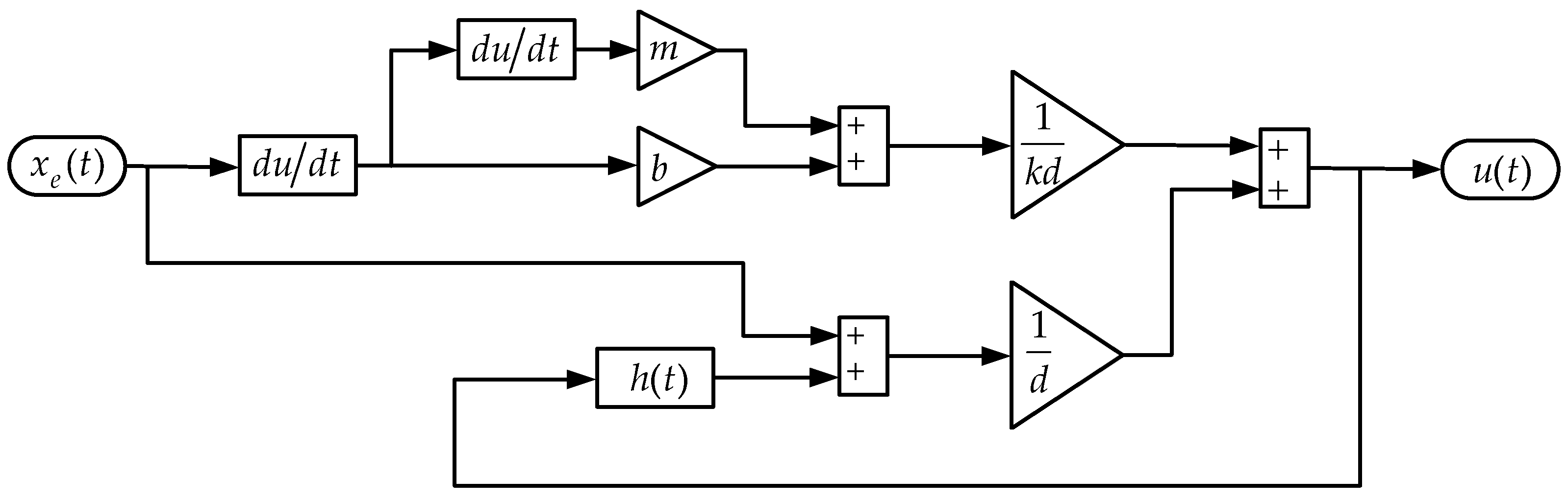
4.1. Inverse Bouc–Wen Hysteresis Model

From the relationship between the inputs and outputs of the actuator given in Equation (3), the inverse hysteresis model based on the Bouc–Wen model can be derived as
  u = m kd x ¨ + b kd x ˙ + 1 d x + h d
According to Equation (7), the inverse hysteresis model controller of the actuator was established as shown in Figure 12, where the corresponding control inputs can be calculated from the desired displacement of the actuator.
The hysteresis compensation results at different frequencies are shown in Figure 13. Clearly, the hysteresis of the actuator is effectively suppressed, though not completely eliminated, and a certain deviation persists between the actual displacement and the desired displacement. This is mainly due to the fact that in the hysteresis model, the damping of the actuator is simplified to linear damping, the order of the Bouc–Wen model is set to first order, and there are some errors in the identification of the model parameters.

4.2. Compound Control

Fuzzy PID control is a control strategy that integrates fuzzy logic with conventional PID control, which can address the performance degradation issues caused by the fixed-gain PID controllers in complex systems. To improve the tracking performance of the actuator and reduce the error between the desired displacement and the actual outputs, a compound control regime was established, and the block diagram of the control system is shown in Figure 14. In compound control, the nonlinear hysteresis of the actuator is suppressed by feedforward control based on the inverse Bouc–Wen model, and the fuzzy PID feedback control is used to compensate for the residual hysteresis and the error between the actual displacement and desired outputs of the actuator caused by external disturbances.
Based on fuzzy rules, the error e and its rate of change ec between the desired displacement and the displacement acquired by the laser displacement sensor are used as control input variables to obtain the parameters in the PID. The parameters of the fuzzy PID are expressed as
k P = k P 0 + Δ k P k I = k I 0 + Δ k I k D = k D 0 + Δ k D
The output increment of the fuzzy controller, Δ k P , Δ k I , and Δ k D , are divided into seven linguistic variables: NB, NM, NS, ZO, PS, PM, and PB. Triangular membership functions were selected for the fuzzy logic system. The fuzzy rules for adjusting Δ k P , Δ k I , and Δ k D are listed in Table 4, Table 5 and Table 6.
The compound control was architected through the feedforward control of the inverse Bouc–Wen model and fuzzy PID feedback control. The results of without control, compound control, and desired output displacement at different frequencies from 10Hz to 60Hz are shown in Figure 15. The results show that compared to the feedforward control of the inverse Bouc–Wen model, the deviation between the output displacement and the desired displacement using compound control is smaller, and the hysteresis suppression performance is further improved.
The errors between the output displacement and the desired displacement of the actuator at different frequencies are presented in Figure 16. As can be seen from this figure, the errors without hysteresis suppression are 30.3 μm, 42.1 μm, 56.6 μm, 66.4 μm, 83.2 μm, and 106.3 μm at frequencies of 10 Hz, 20 Hz, 30 Hz, 40 Hz, 50 Hz, and 60 Hz, respectively. Figure 17 shows the FFT results of the Bouc–Wen and compound control errors. Observing Figure 16, from 10 Hz to 60 Hz, the errors of the inverse Bouc–Wen model are 3.68 μm, 3.63 μm, 4 μm, 9.1 μm, 6.93 μm, and 9.84 μm, and the errors of the compound control are 2.15 μm, 2.28 μm, 2.57 μm, 5.94 μm, 4.15 μm, and 6.02 μm. Figure 16 and Figure 17 demonstrate that on the basis of feedforward compensation, the errors of the compound control are further reduced by 41.5%, 37.2%, 35.8%, 34.7%, 40.1%, and 38.8%, respectively.

5. Conclusions

This research proposed a compound control regime, which significantly suppressesd the hysteresis of a rhombic frame piezoelectric actuator used in an active rotor with TEFs. The conclusions are as follows:
(1)
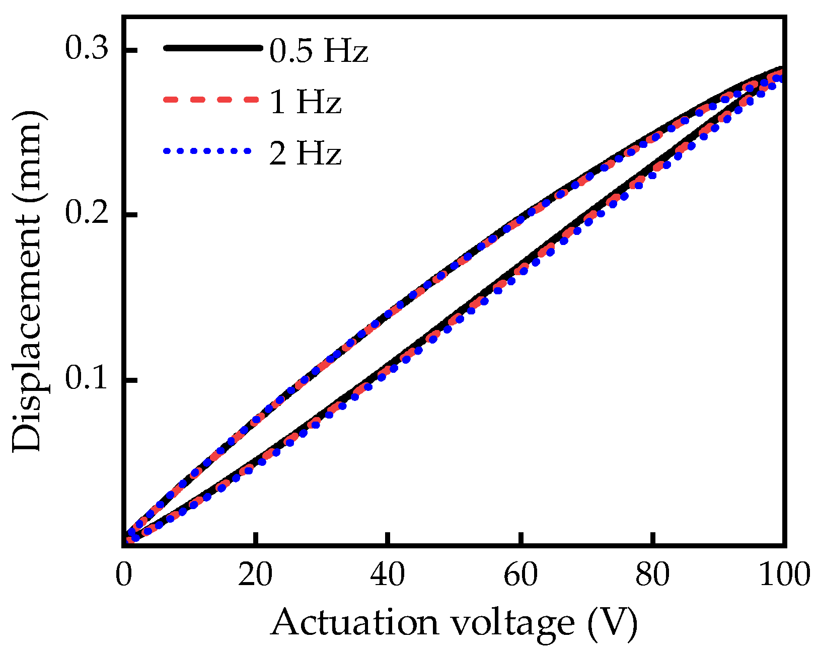
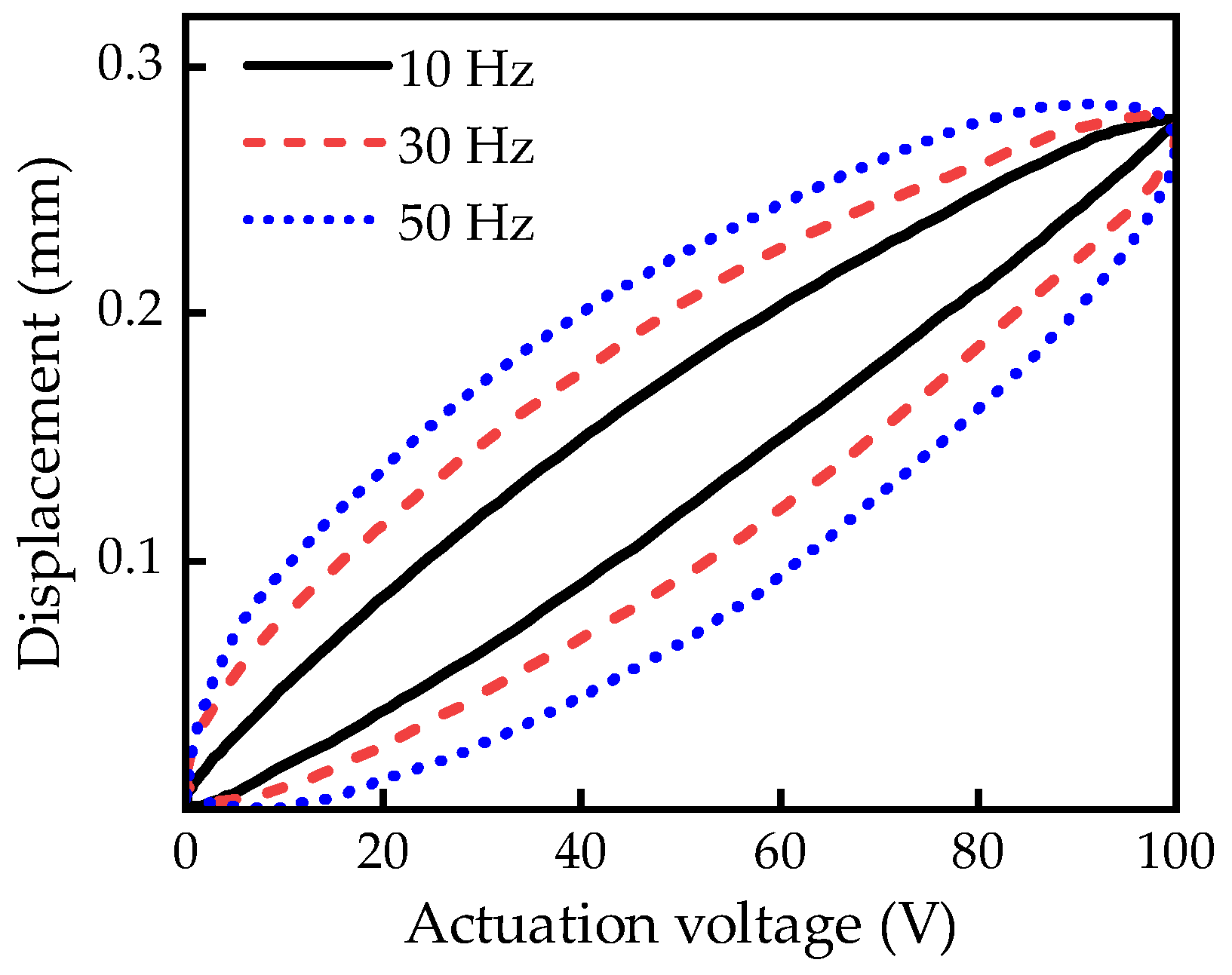
Bench-top tests were conducted to study the hysteresis characteristics of the piezoelectric actuator. The test results showed that when the actuation frequencies are lower than 10 Hz, the hysteresis of the piezoelectric actuator is mainly determined by the characteristics of the piezoelectric materials, and the hysteresis curves of the piezoelectric actuator are almost identical. As the frequency of the actuation signal increases, the system characteristics of the actuator such as mass, damping, and stiffness will become more and more significant in the actuator hysteresis.
(2)
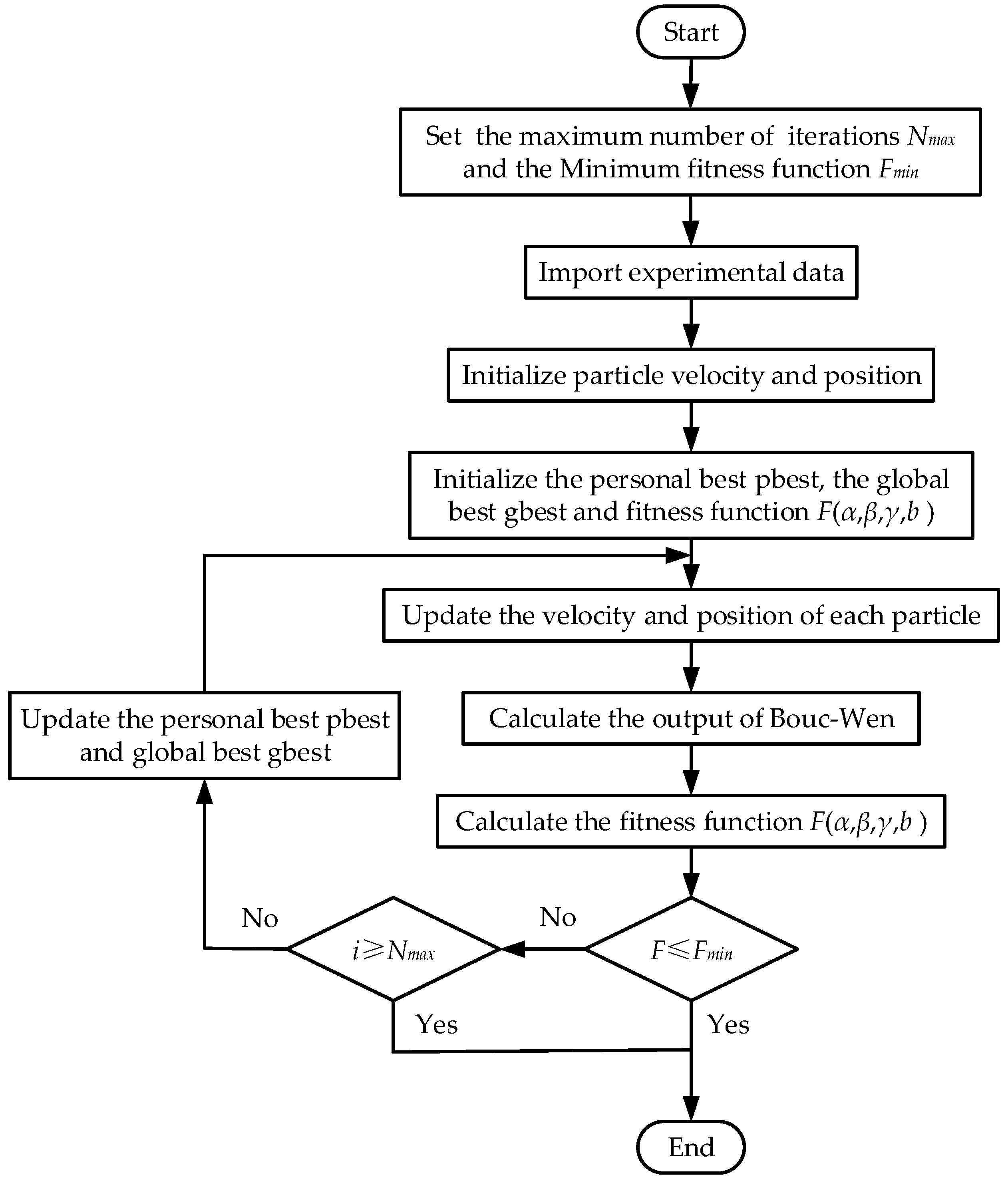
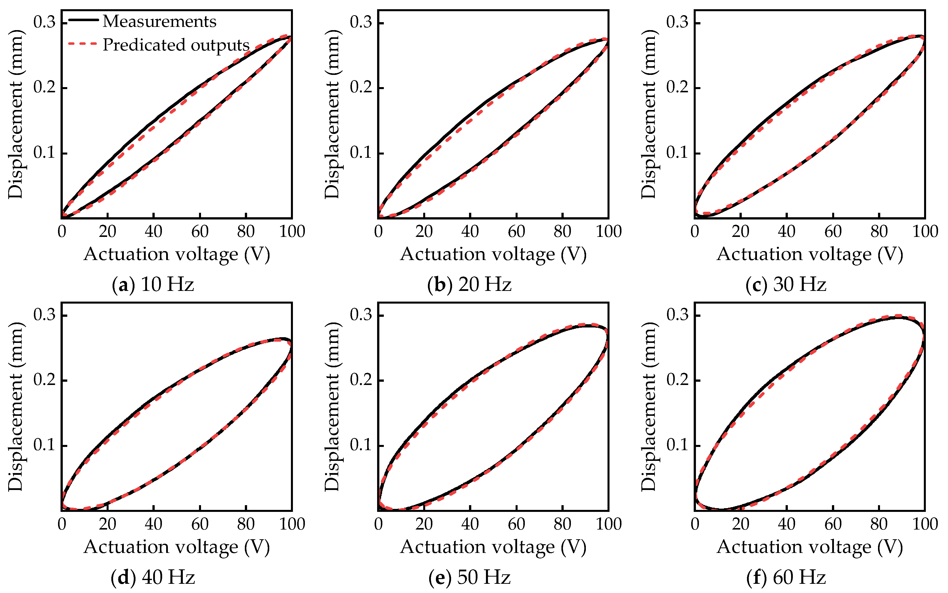
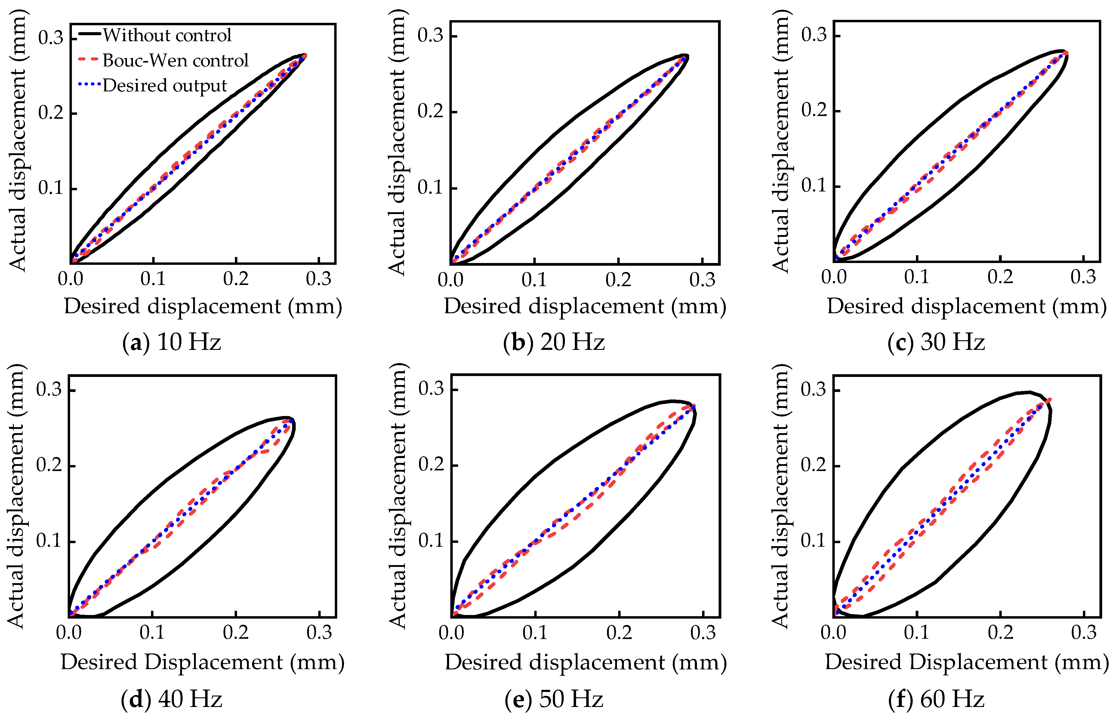
The Bouc–Wen model was utilized to depict the actuator hysteresis behavior within the bandwidth range of 1 Hz to 60 Hz, and the PSO algorithm was used to identify the parameters of the Bouc–Wen model. The measurement and simulation results indicated that the Bouc–Wen model could accurately capture the hysteresis behavior of the actuator, which lay a foundation for hysteresis compensation.
(3)
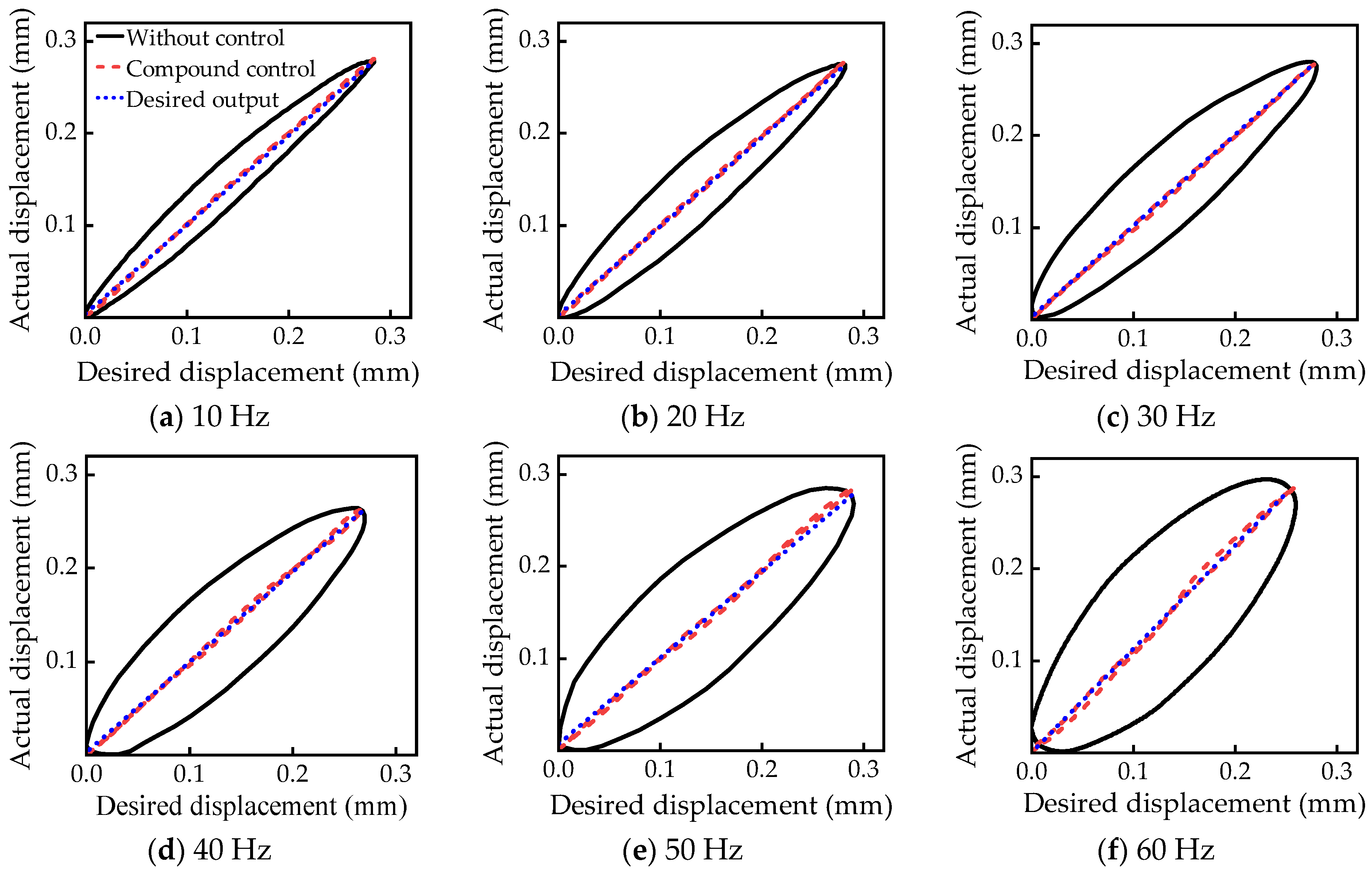
Based on the inverse Bouc–Wen model and fuzzy PID feedback control, the compound control method was developed. Experimental results demonstrated that the hysteresis behavior of the piezoelectric actuator in the frequency bandwidth from 10 Hz to 60 Hz could be significantly suppressed. This method integrates a traditional rate-dependent model with fuzzy control, thus enhancing the adaptability and robustness of the hysteresis suppression in piezoelectric actuators for the active rotor.
The compound control regime will be integrated into the two-bladed active rotor control system in the future to further validate its performance in the rotor operating conditions. Efforts will also be made to improve the vibration control performance of active rotors with TEFs by utilizing this hysteresis suppression method. These improvements will support the application of this technology in the helicopter vibration reduction field using active rotors with TEFs.

Author Contributions

Conceptualization, X.G.; methodology, X.G.; software, X.G.; data processing, X.G.; validation, L.D.; writing—original draft preparation, X.G.; writing—review and editing, J.Z.; supervision, W.Y.; project administration, L.D.; funding acquisition, J.Z. All authors have read and agreed to the published version of the manuscript.

Funding

This research was funded by the National Key Laboratory of Helicopter Aeromechanics Foundation of China (2023-HA-LB-067-03), the Key Laboratory of Rotor Aerodynamics Foundation (RAL202302-6) and the Natural Science Foundation of Jiangsu Province (BK20241420).

Data Availability Statement

Data can be available from the corresponding authors.

Conflicts of Interest

The authors declare no conflicts of interest.

References

  1. Bertolino, A.C.; Gaidamo, M.; Smorto, S.; Porro, P.G.; Sorli, M. Development of a High-Performance Low-Weight Hydraulic Damper for Active Vibration Control of the Main Rotor on Helicopters—Part 1: Design and Mathematical Model. Aerospace 2023, 10, 391. [Google Scholar] [CrossRef]
  2. Breitbach, E.; Buter, A. The main sources of helicopter vibration and noise emissions and adaptive concepts to reduce them. J. Struct. Control. 1996, 3, 21–32. [Google Scholar] [CrossRef]
  3. Friedmann, P.P. On-blade control of rotor vibration, noise, and performance: Just around the corner? J. Am. Helicopter Soc. 2014, 59, 1–37. [Google Scholar] [CrossRef]
  4. Zhou, J.L.; Dong, L.H.; Yang, W.D. Experimental study on transfer functions of an active rotor under different flight conditions. Chin. J. Aeronaut. 2022, 35, 107–120. [Google Scholar] [CrossRef]
  5. Wu, Q.L.; Zhao, N.; Yao, M.H.; Niu, Y.; Wang, C. Free vibrations and frequency sensitivity of bionic microcantilevers with stress concentration effect. Int. J. Struct. Stab. Dy. 2025, 26, 265022. [Google Scholar] [CrossRef]
  6. Napole, C.M. Advanced control of piezoelectric actuators. Ph.D. Thesis, University of the Basque Country, Euskad, Spain, 2022. [Google Scholar]
  7. Nie, Z.G.; Cui, Y.G.; Huang, J.; Wang, Y.Q.; Chen, T.H. Precision open-loop control of piezoelectric actuator. J. Intel. Mat. Syst. Str. 2022, 33, 1198–1214. [Google Scholar] [CrossRef]
  8. Kurdila, A.J.; Li, J.; Strganac, T.; Webb, G. Nonlinear control methodologies for hysteresis in PZT actuated on-blade elevons. J. Aerosp. Eng. 2003, 16, 167–176. [Google Scholar] [CrossRef]
  9. Viswamurth, S.R.; Ganguli, R. Effect of piezoelectric hysteresis on helicopter vibration control using trailing-edge flaps. J. Guid. Control. Dyn. 2006, 29, 1201–1209. [Google Scholar] [CrossRef]
  10. Viswamurth, S.R.; Ganguli, R. Modeling and compensation of piezoceramic actuator hysteresis for helicopter vibration control. Sens. Actuators A Phys. 2007, 135, 801–810. [Google Scholar] [CrossRef]
  11. Viswamurth, S.R.; Rao, A.K.; Ganguli, R. Dynamic hysteresis of piezoceramic stack actuators used in helicopter vibration control: Experiments and simulations. Smart Mater. Struct. 2007, 16, 1109–1119. [Google Scholar] [CrossRef]
  12. Muir, E.R.; Friedmann, P.P.; Kumar, D. Effect of piezoceramic actuator hysteresis on helicopter vibration and noise reduction. J. Guid. Control. Dyn. 2012, 35, 1299–1311. [Google Scholar] [CrossRef]
  13. Muir, E.R.; Friedmann, P.P.; Kumar, D. Hysteresis characterization in piezoceramic stack actuators and its influence on vibration and noise reduction in helicopters using actively controlled flaps. In Proceedings of the 51st AIAA/ASME/ASCE/AHS/ASC Structures, Structural Dynamics, and Materials Conference, Orlando, FL, USA, 12–15 April 2010. [Google Scholar]
  14. Ganguli, R.; Viswamurth, S.R. Piezoelectric actuators in helicopter active vibration control. In Micro and Smart Devices and Systems; Springer: New Delhi, India, 2014; pp. 111–125. [Google Scholar] [CrossRef]
  15. Kanchan, M.; Santhya, M.; Bhat, R.; Naik, N. Application of Modeling and Control Approaches of Piezoelectric Actuators: A Review. Technologies 2023, 11, 155. [Google Scholar] [CrossRef]
  16. Hao, G.L.; Cao, K.R.; Li, R.; Li, Z.; Du, H.; Tan, L.Y. Rate-dependent hysteresis modeling and compensation for fast steering mirrors. Sens. Actuators A Phys. 2024, 376, 115568. [Google Scholar] [CrossRef]
  17. Cai, J.N.; Dong, W.; Nagamune, R. A survey of Bouc-Wen hysteretic models applied to piezo-actuated mechanical systems: Modeling, identification, and control. J. Intel. Mat. Syst. Str. 2023, 34, 1843–1863. [Google Scholar] [CrossRef]
  18. Zhang, Z.X.; Zhang, G.H.; Wang, S.X.; Shi, C.Y. hysteresis modeling and compensation for tendon-sheath mechanisms in robot-assisted endoscopic surgery based on the modified Bouc-Wen model with decoupled model parameters. IEEE Trans. Med. Robot. Bionics 2023, 5, 218–219. [Google Scholar] [CrossRef]
  19. Yu, L.H.; Zhang, X.M.; Lai, J.H.; Fatikow, S. Tracking control of a piezo-actuated compliant mechanism based on an improved Bouc-Wen hysteresis model with variable parameters. Aip Adv. 2023, 13, 055129. [Google Scholar] [CrossRef]
  20. Zhang, Y.; Lu, J.J.; Huang, Z.X.; Feng, B. Modeling and hysteresis inverse compensation control of soft pneumatic gripper for gripping phosphorites. Actuators 2025, 14, 193. [Google Scholar] [CrossRef]
  21. Li, X.Q.; Hu, K.M.; Li, H.; Wang, B.; Xu, S.; He, Y.C. Adaptive hysteresis compenstion control of a macro-fiber composite bimorph by improved rein forcement learning. J. Intel. Mat. Syst. Str. 2024, 35, 1471–1482. [Google Scholar] [CrossRef]
  22. Zhou, J.L.; Dong, L.H.; Yang, W.D. Hysteresis Compensation for a Piezoelectric Actuator of Active Helicopter Rotor Using Compound Control. Micromachines 2021, 12, 1298. [Google Scholar] [CrossRef] [PubMed]
  23. Sun, W. Research on Real-Time Tuning of PID Parameters Based on Fuzzy Control. In Proceedings of the IEEE 2nd International Conference on Image Processing and Computer Applications, Shenyang, China, 28–30 June 2024. [Google Scholar] [CrossRef]
Figure 1. Active rotor with TEFs.
Actuators 14 00327 g001
Figure 2. Structure of drive system.
Actuators 14 00327 g002
Figure 3. Rhombic frame piezoelectric actuator.
Actuators 14 00327 g003
Figure 4. Experimental setup.
Actuators 14 00327 g004
Figure 5. Hysteresis curves at low frequencies.
Actuators 14 00327 g005
Figure 6. Hysteresis curves at high frequencies.
Actuators 14 00327 g006
Figure 7. Bouc–Wen model for calculating h .
Actuators 14 00327 g007
Figure 8. Hysteresis model.
Actuators 14 00327 g008
Figure 9. Flowchart of PSO identification.
Actuators 14 00327 g009
Figure 10. Comparison of measurements and model-predicted outputs at 1 Hz.
Actuators 14 00327 g010
Figure 11. Comparison of measurements and model-predicted outputs at different frequencies.
Actuators 14 00327 g011
Figure 12. Block diagram of the inverse Bouc–Wen model for calculating h 1 .
Actuators 14 00327 g012
Figure 13. Inverse model control at different frequencies.
Actuators 14 00327 g013
Figure 14. Block diagram of compound control.
Actuators 14 00327 g014
Figure 15. Compound control at different frequencies.
Actuators 14 00327 g015
Figure 16. Displacement error.
Actuators 14 00327 g016
Figure 17. Displacement error of different frequencies at the frequency domain.
Actuators 14 00327 g017
Table 1. Parameters of the rhombic frame actuator.
ParameterValue
Preload (N)1400
Dimensions (mm)155 × 55 × 10
Maximum displacement (mm)0.58
Mass (g)242.6
Blocking force (N)447
Stiffness (N/mm)768.6
Resonance frequency (Hz)566.4
Table 2. Information about the piezoelectric stack.
SourcePiezomechanik Gmbh Company
TypeHard
Dimensions (mm)18 × 10.1 × 10.1
d33 (pm/V)635
Mechanical quality factor 70
Table 3. The identified parameters of the Bouc–Wen model.
ParameterValue
m (kg)0.0607
b (N·s·m−1)1250
k (N/m)7.68 × 105
d (mm/V)2.98 × 10−6
α0.469
β0.114
γ0.01
Table 4. Fuzzy rules for Δ k P .
eNBNMNSZOPSPMPB
ec
NBPBPBPMPMPSZOZO
NMPBPBPMPSPSZONS
NSPMPMPMPSZONSNS
ZOPMPMPSZONSNMNM
PSPSPSZONSNSNMNM
PMPSZONSNMNMNMNB
PBZOZONMNMNMNBNB
Table 5. Fuzzy rules for Δ k I .
eNBNMNSZOPSPMPB
ec
NBNBNBNMNMNSZOZO
NMNBNBNMNSNSZOZO
NSNBNMNSNSZOPSPS
ZONMNMNSNSZOPSPS
PSNMNSZOPSPSPBPB
PMZOZOPSPSPMPBPB
PBZOZOPSPMPMPBPB
Table 6. Fuzzy rules for Δ k D .
eNBNMNSZOPSPMPB
ec
NBPSNSNBNBNMNMPS
NMPSNSNBNMNMNSZO
NSZONSNMNMNSNSZO
ZOZONSNSNSNSNSZO
PSZOZOZOZOZOZOZO
PMPBNSPSPSPSPSPB
PBPBPMPMPMPSPSPB
Disclaimer/Publisher’s Note: The statements, opinions and data contained in all publications are solely those of the individual author(s) and contributor(s) and not of MDPI and/or the editor(s). MDPI and/or the editor(s) disclaim responsibility for any injury to people or property resulting from any ideas, methods, instructions or products referred to in the content.

