Article

Dynamic Error Compensation Control of Direct-Driven Servo Electric Cylinder Terminal Positioning System

1
School of Electromechanical Engineering and Automation, Shanghai University, Shanghai 200444, China
2
School of Electrical Engineering and Automation, Jiangsu Normal University, Xuzhou 221116, China
*
Authors to whom correspondence should be addressed.
Actuators 2025, 14(7), 317; https://doi.org/10.3390/act14070317
Submission received: 14 April 2025 / Revised: 21 June 2025 / Accepted: 23 June 2025 / Published: 25 June 2025
(This article belongs to the Section Control Systems)

Abstract

In this work, we aimed to determine the nonlinear disturbance caused by cascaded coupling rigid–flexible deformation and friction in a direct-driven servo electric cylinder terminal positioning system (DDSEC-TPS) during feed motion of an intermittent, reciprocating, and time-varying load. For this purpose, a cascaded coupling dynamic error model of DDSEC-TPS was established based on the position–pose error model of the parallel motion platform and the rotor field-oriented vector transform. Then, a model to observe the dynamic error of the DDSEC-TPS was established using the improved beetle antennae search algorithm backpropagation neural network (IBAS-BPNN) prediction model according to the rigid–flexible deformation error theory of feed motion, and the observed dynamic error was compensated for in the vector control strategy of the DDSEC-TPS. The length and error prediction models were trained and validated using opposite and mixed datasets tested on the experimental platform, to observe dynamic errors and evaluate and optimize the prediction models. The experimental results show that dynamic error compensation can improve the position tracking accuracy of the DDSEC-TPS and the position–pose performance of the parallel motion platform. This study is of great significance for improving the consistency of following multiple DDSEC-TPSs and the position–pose accuracy of parallel motion platforms.

1. Introduction

The six-degree-of-freedom (DOF) parallel motion platform has the advantages of a compact structure, high stiffness, and strong bearing capacity. Therefore, it is widely used in scientific research and professional training fields [1,2]; for example, in high-fidelity dynamic simulation [3] and high-precision spatial pose docking [4]. It is a typical pose trajectory motion system that adopts multiple intelligent actuators for cooperative control. The system’s structure, as shown in Figure 1, comprises six actuators, a moving platform, and a static platform. The actuators provide not only the power feed for the multi-DOF parallel motion platform but also spatial mechanism support. The pose motion tracking accuracy of the 6-DOF parallel motion platform within the workspace envelope depends on the tracking accuracy of the end positioning of the actuators and their dynamic transmission performance [5,6,7]. The direct-driven servo electric cylinder (DDSEC) is a recently advanced actuator type with an electromagnetic field as the medium and power drive, and mechanical transmission as characteristics. A permanent magnet synchronous machine (PMSM) directly cascades with the ball screw and piston rod via coupling to realize terminal positioning. A direct-driven servo electric cylinder terminal positioning system (DDSEC-TPS) exhibits the distinct advantages of a compact structure, high transmission efficiency, multi-point positioning, and high positioning accuracy [8,9].
With the development of parallel motion platforms towards being high-speed, light-weight, and high-precision, due to the influence of system integration complexity and cost performance, the semi-closed-loop control structure [9] with cascaded coupling of a rotary motor and ball screw is widely used in DDSECs worldwide. However, this control structure includes not only cascaded cross-coupling among the electromagnetic energy conversion, mechanical transmission, and control loop [4,10,11], but also the parameter coupling relationship between the power drive and mechanical rigid–flexible transmission [12,13,14]. Additionally, during the operation of fast start–stop, high-frequency–high-speed reciprocating, and time-varying feed with a wide range of loads, the system is affected by nonlinear time-varying factors, such as cascaded coupling parameter perturbation, energy control constraints, vibration and shock [15,16,17], and magnetic circuit saturation. These factors are prone to terminal positioning interference caused by rigid–flexible deformation and dynamic frictional coupling [16,18,19]. This is because the mechanical transmission link is not included in the control loop, which easily leads to inaccurate end positioning and system instability. To solve these problems, domestic and international experts have conducted extensive research [20,21,22,23,24] on the mechanism of the generation of dynamic error, rigid–flexible deformation dynamic error models, and frictional disturbance characteristics in DDSEC-TPSs. In [13], an integrated model of a ball screw servo feed system was established, and the coupling characteristics among the model parameters were analyzed. In [14], a novel mechanical model of a ball screw-driven stage was proposed to analyze the elastic deformation dynamics and characteristics under various motion conditions. Kamalzadeh et al. reported that under action of the driving inertial force, friction force, and load force, the ball screw feed system produces rigid–flexible deformation, system parameter perturbation, and nonlinear friction and causes hysteresis, vibration, and disturbance of terminal positioning. The resulting power drive, mechanical transmission, and control errors reduce the dynamic end positioning accuracy, making it difficult to follow motion control in real time and with high precision [7,9,18].
Additionally, it is difficult to treat elastic deformation and friction models with dynamic equations under coupled effects of rigid–flexible deformation and dynamic friction because the level of precision associated with actual elastic deformation and friction characteristics and parameter tuning is difficult to realize in a DDSEC-TPS. To solve the uncertainty in the dynamic error in a DDSEC-TPS, it is necessary to further develop a dynamic error observer for rigid–flexible deformation and determine friction parameters. To address this challenge, a method, based on the identification of the axial deformation parameters of the feed transmission components in TPS modeling, specifically, a dynamic tracking error model, was proposed in [9,14]. To address the uncertainty of the dynamic error of terminal positioning in the system, the dynamic error observer of the rigid–flexible deformation caused by dynamic error and parameter identification must be systematically investigated. Xiang et al. proposed a comprehensive identification method for the structural and friction parameters of a feed servo system [25,26].
To enhance the terminal positioning accuracy, dynamic error compensation controllers have been implemented in DDSEC-TPSs to suppress or eliminate dynamic errors [27,28,29,30,31,32,33,34,35,36]. Zhai established a feed-forward compensation controller for a mechanical stiffness model of the drive part of a DDSEC to reduce the steady-state error and improve the robustness of the system [20]. Subsequently, dynamic error compensation control of data-driven rigid–flexible deformation error observation and friction parameter identification was gradually adopted. In [7,31,32,33], an artificial neural network mapping method was used to calculate the position error, and appropriate compensation was introduced into the control loop to reduce the terminal positioning error. However, this method requires a large number of training datasets before it can be applied in industry. In [37], a PID controller optimization algorithm combining Particle Swarm Optimization (PSO) with BP neural network is introduced into the servo control system, which makes the tracking error curve of the upper platform smoother, brings tracking motion closer to the theoretical value, and improves the control accuracy. Therefore, dynamical error compensation control of a DDSEC-TPS is an effective way to improve the accuracy of the posture and trajectory of the parallel motion platform used in a dynamic simulation of motion effects.
To address the problem of rigid–flexible deformation and friction disturbance of the electric cylinder in a high-speed feed operating under intermittent, reciprocating rotation and dynamic load change, a dynamic error model of a DDSEC-TPS is established. This model is based on the position and pose motion error model of a parallel motion platform and the rotor magnetic field orientation vector control principle. Subsequently, by integrating the rigid–flexible deformation error theory of DDSEC-TPS mechanical transmission, dynamic error compensation control of rigid–flexible deformation error observation is developed based on the improved beetle antennae search algorithm backpropagation neural network (IBAS-BPNN) prediction model. Finally, the effectiveness of the dynamic error observation and compensation control strategy of the DDSEC-TPS is validated through system modeling simulation and experimental results.

2. Dynamical Model

2.1. Dynamical Error Model of Parallel Motion Platform

The dynamic perception of human-in-the-loop motion effect simulation was realized by using a simulation signal generator (A), a direct-driven electric cylinder (B), and the dynamic platform (C) of a parallel motion platform (see Figure 2). The pose motion accuracy of the parallel motion platform directly determines the fidelity of the dynamic simulation of the motion effect. Specifically, the kinematic behavior of the parallel motion platform is an external manifestation of its underlying dynamics. Therefore, the dynamic error models of the DDSEC-TPS must be derived from analyzing the dynamics and pose error theory of parallel motion platforms.

2.1.1. Dynamics of Parallel Motion Platform

The dynamic structure of the 6-DOF parallel motion platform is depicted in part C of Figure 2. The dynamic equation of the parallel motion platform can be expressed as follows [1,2,3]:
J q T q T m = M s q q ¨ + C s q , q ˙ q ˙ + G s q
where q , q ˙ , and q ¨ 6 denote the generalized coordinate pose, generalized velocity, and generalized acceleration of the parallel motion platform, respectively. Furthermore, J q T q 6×6 denotes the Jacobian matrix of the system, T m 6, denotes the drive torque supplied via the servo electric cylinders, M s ( q ) 6×6 denotes the term matrix of the system mass inertia, C s q , q ˙ 6×6 denotes the coefficient matrix of the Coriolis and centrifugal forces of the system, and G s q 6 denotes the term matrix of the system’s gravity vector.

2.1.2. Kinematics and Error Model of the Actuator

By solving the hinge direction vector using the closed-loop vector method, the terminal positioning motion equation of the actuator can be obtained as follows:
x n , i u i = R r a , i + h p r b , i
where i represents the ith actuator with i 1 , 6 , x n denotes the expansion length of the actuator, u denotes the unit direction vector of the actuator, R denotes the rotation transformation matrix, r a denotes the radius of the upper platform, r b denotes the radius of the static platform, and h p denotes the vertical distance between the platform planes.
The pose change speed of the parallel motion platform is converted into the speed of the actuator terminal positioning via Jacobian matrix transformation, and the terminal positioning speed equation of the actuators can be obtained as follows:
x ˙ n , i u i = J q T ( q ) q ˙
where x ˙ n denotes the stretch speed of the actuator.
The error model of the actuators can be expressed as follows:
x n , 1 x n , 2 x n , 3 x n , 4 x n , 5 x n , 6 = u 1 T ( u 1 × r a 1 ) T u 2 T ( u 2 × r a 2 ) T u 6 T ( u 6 × r a 6 ) T p θ + u 1 T R u 1 T 0 0 0 0 0 0 u 6 T R u 6 T r a 1 r b 1 r a 6 r b 6
where p = p x p y p z , θ = θ x θ y θ z , and p x , p y and p z are the linear displacements of the parallel motion platforms in the x-, y-, and z-axes, respectively. Furthermore, θ x , θ y , and θ z are the angular displacements of the parallel motion platform in the x-, y-, and z-axes, respectively.
Equation (4) can be expressed as follows:
X n , i = J m P + J n C
where X n , i = x n , 1 x n , 2 x n , 3 x n , 4 x n , 5 x n , 6 T R 6 × 1 ,
P = p θ 6 × 1 ,   J m = u 1 T u 1 × r a 1 T u 6 T u 6 × r a 6 T 6 × 6
C = r a 1 r b 1 r a 6 r b 6 6 × 1 ,   J n = u 1 T R u 1 T 0 0 0 0 0 0 u 6 T R u 6 T 6 × 36
The platform pose error model obtained from the rearrangement of Equation (5) is
P = J m 1 X n , i J m 1 J n C = J m 1 ( X n , i J n C ) = k e a e a
where k e denotes the error model transfer matrix, with k e a = J m 1 , J m 1 J n ; and e a denotes the parameter vector errors of the actuators, with e a = X n , i , C T .
The actuator error model demonstrates an intrinsic correlation mapping relationship between the terminal positioning of the actuators and the pose motion of the parallel motion platform. Furthermore, it indicates that the actuators affect the real-time pose motion of the moving platform because of nonlinear factors such as rigid–flexible deformation and friction disturbance.

2.2. Dynamical Error Model of DDSEC-TPS

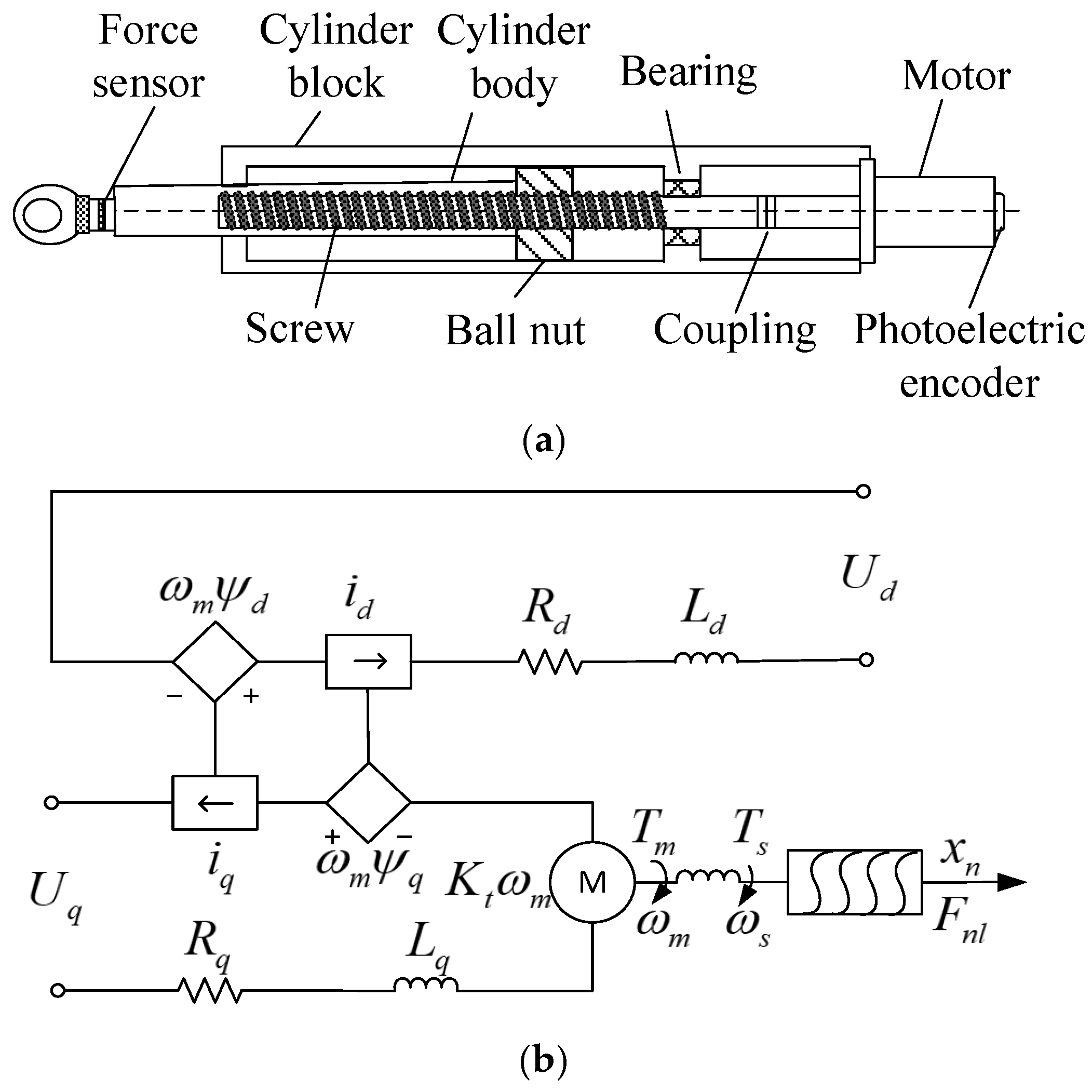
The DDSEC-TPS is a mechatronic cascade-coupled actuator featuring an integrated modular design of a servo motor, ball screw–nut pair, and piston rod. Utilizing vector control theory, the PMSM serves as the power drive source, converting electrical rotational motion into reciprocating linear motion of the piston rod through the ball screw–nut mechanism, thereby enabling precise position tracking and positioning of the mechanical transmission output [4,8,9]. The structure and operating principles are illustrated in Figure 3. As shown in Figure 3a, the DDSEC-TPS uses coupling to connect the servo PMSM and ball screw–nut pair, forming an equivalent electromechanical cascaded coupling double inertial mass system that serves as a physical carrier for realizing electromagnetic energy transfer and electromechanical energy conversion. The DDSEC-TPS can realize the terminal positioning function by using PMSM power-driven ball screw–nut pairs to complete the mechanical feed movement [10,11].

2.2.1. Dynamic Equation of PMSM Power Driver

As depicted in Figure 3b, it is assumed that the magnetic circuit remains unsaturated, and the influence of hysteresis and eddy current loss is disregarded. Furthermore, the spatial magnetic field presents a sinusoidal distribution [4,10,11], and a dynamic model in the d - q rotating coordinate system can be obtained based on the indirect orientation vector transformation of the rotor magnetic field, which comprises voltage, flux, torque, and motion equations.
The voltage equation is as follows [8,9,10,11]:
u d , i = R s , i i d , i + d ψ d , i d t ω m , i ψ q , i u q , i = R s , i i q , i + d ψ q , i d t + ω m , i ψ d , i
where u d and u q denote the equivalent voltages on the d- and q-axes, respectively; R s denotes the stator resistance, i d and i q denote the equivalent currents on the d- and q- axes, respectively, ψ d and ψ q are the equivalent flux linkages on the d- and q-axes, respectively, and ω m denotes the angular velocity on the output axis of the PMSM.
The flux linkage equation is as follows [8,9,10,11]:
ψ d , i = L d , i i d , i + ψ f , i ψ q , i = L q , i i q , i
where L d and L q denote the equivalent inductances on the d- and q-axes, respectively, and ψ f denotes the equivalent flux linkage of the permanent magnet.
The torque equation is as follows [8,9,10,11]:
T m , i = 3 2 P n , i ( ψ d , i i q , i ψ q , i i d , i )
where p n denotes the number of magnetic pole pairs in the PMSM.
The equation of motion is as follows [8,9,10,11]:
J m e q , i P n , i d ω m , i d t = T m , i T m l , i B m e q , i ω m , i d θ m , i d t = ω m , i
where J m e q , B m e q , and T m l denote the equivalent moments of inertia, viscous damping coefficient, and load torque of the DDSEC-TPS, respectively, and θ m denotes the angular displacement on the output axis of the PMSM.

2.2.2. Dynamic Equation of Mechanical Feed Drive

On the ball screw side, the drive torque T s , ω s , and θ s are used to achieve mechanical feed transmission. The drive torque can be expressed as follows [12,13]:
T s , i ( t ) = K c o , i [ θ m , i ( t ) θ s , i ( t ) ]
where K c o denotes the stiffness coefficient of the coupling, and θ s denotes the angular displacement of the output shaft of the ball screw.
The torque balance equation of the ball screw is as follows:
J s , i d 2 θ s , i d t 2 + B s , i d θ s , i d t + K s , i θ s , i + T s l , i = T s , i
where J s , B s , and K s denote the moment of inertia, damping coefficient, and elastic stiffness coefficient of the ball screw–nut pair, respectively, and T s l denotes the equivalent load torque, including all the load and friction forces.
The expressions for the driving force and displacement movement transformation of the ball screw–nut pair are as follows [12,13]:
f n , i = 2 π η s , i T s l , i L s , i . sgn ( ω m )
x n , i = L s , i θ s , i 2 π
where η s denotes the transmission efficiency of the ball screw–nut pair, L s denotes the lead of the ball-lead screw, and s g n ( ) denotes the positive and negative angular velocity sign function.
The equivalent dynamic equation of the translational system on the side of the ball nut pair can be expressed as follows:
m n , i d 2 x n , i d t 2 + B n , i d x n , i d t + K n , i x n , i + f n l , i + f n f r i , i = f n , i
where m n and x n denote the equivalent load mass and axial translational displacement of the nut and piston rod, respectively; f n , f n f r i , and f n l denote the driving force, friction force, and load force on the piston rod of the electric cylinder, respectively, and B n and K n are the equivalent damping coefficient and stiffness coefficient of the ball screw–nut pair, respectively.

2.3. Dynamic Equation of Sevo Electric Cylinder

The dynamic equation of the DDSEC-TPS can be obtained by rearranging Equations (7)–(15) as follows:
u d , i = R s , i i d , i + L d , i d i d , i d t P n , i ω m , i L q , i i q , i u q , i = R s , i i q , i + L q , i d i q , i d t + P n , i ω m , i ( L d , i i d , i + ψ f , i ) J m e q d ω m , i d t = 3 2 P n , i [ ψ f , i i q , i + ( L d , i L q , i ) i d , i i q , i ] B m e q , i ω m , i K c o , i ( θ m , i θ s , i ) a i d 2 x n , i d t 2 + b i d x n , i d t + c i x n , i = d i θ m , i d t + e ( f n l , i + f n f , i )
where a = J s 2 π L s + L s m n 2 π η s , b = B s 2 π L s + L s B n 2 π η s , c = 2 K s 2 π L s + L s K n 2 π η s , and d = K c o   , e = L s m n 2 π η s .
By substituting (14) into (16) and rearranging the first-order differential equations, DDSEC-TPS state equation can be obtained as follows:
L d , i d i d , i d t = u d , i R s , i i d , i + P n , i ω m , i L q , i i q , i L q , i d i q , i d t = u q , i R s , i i q , i P n , i ω m , i ( L d , i i d , i + ψ f , i ) J m e q , i d ω m , i d t = 3 2 P n , i [ ψ f , i i q , i + ( L d , i L q , i ) i d , i i q , i ] B m e q , i ω m , i K c o , i ( θ m , i θ s , i ) d θ s , i d t = 2 π L s , i x n , i a i d x n , i d t = b i c i L s , i 2 π θ s , i + d i θ m , i + e i ( f n l , i + f n f , i )
The output equation of the DDSEC-TPS is as follows:
x n , i = x ˙ n , i d t .
The constraint equations of the DDSEC-TPS’ power, current, angular velocity, and feed stroke are as follows:
i d , i 2 R s + i q , i 2 R s P n i d , i 2 + i q , i 2 i s , i 2 ω m ± 2 π n e x n L n max .
According to Equations (17)–(19), the DDSEC-TPS is a typical electromechanical cascaded-coupled system in each motion link of the parallel motion platform, and the dynamic equation represents the physical and mathematical relationship between the electromagnetic and mechanical coupling parameters among the components of each moving link.

2.4. Dynamic Error Model of DDSEC-TPS

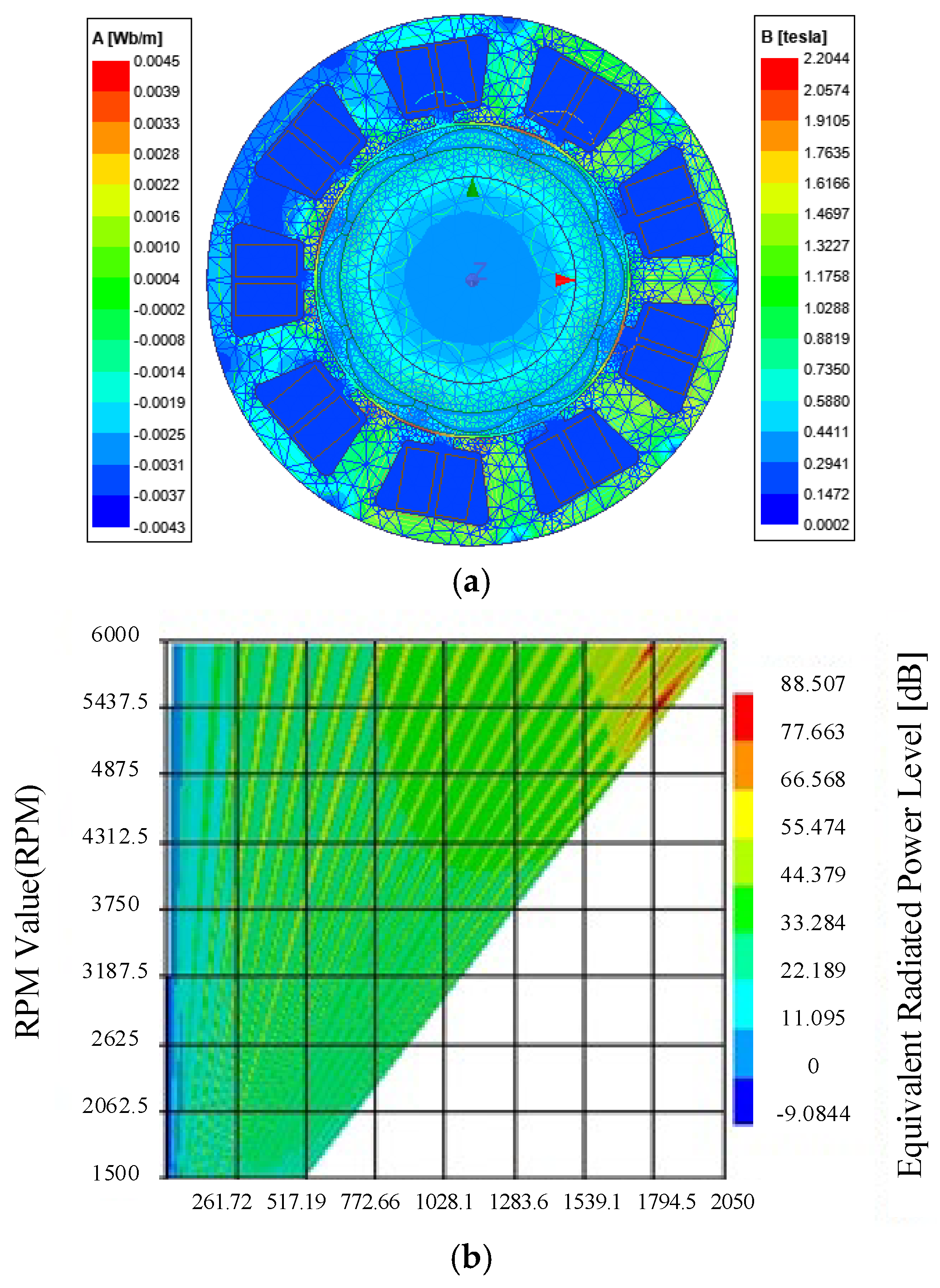
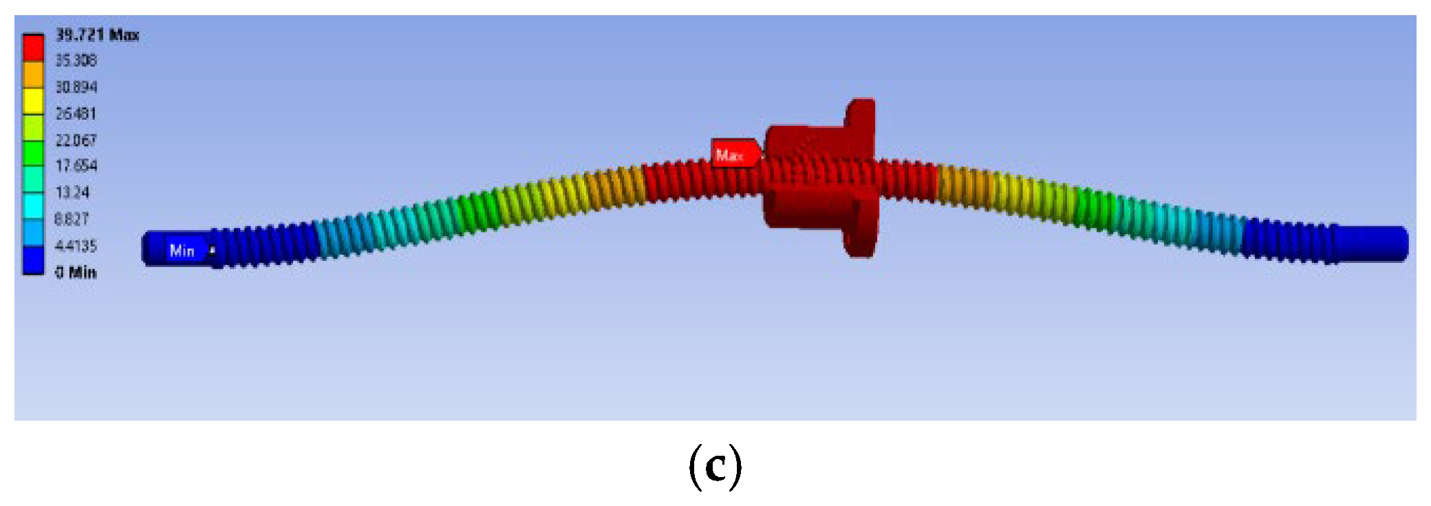
Owing to the existence of an air-gap magnetic field in the slots of the PMSM stator core, the rotor is affected by the main wave magnetic field and tooth–groove harmonics during rotation [38]. The magnetic resistance changes in the magnetic circuit, resulting in changes in the magnetic field energy and the vibration noise generated at low and high speeds. The electromagnetic analysis, modal analysis, and harmonic response of the DDSEC-TPS model can be used to obtain the uneven air-gap magnetic flux density of the PMSM, multi-speed harmonic response produced by the electromagnetic stress acting on the housing, and the vibration and deformation of the ball screw, as shown in Figure 4. In the process of time-varying voltage excitation and load disturbance, the state, system, and load parameters of DDSEC-TPS change dynamically. Vibration and noise affect the performance and accuracy of DDSEC-TPS terminal positioning, resulting in a dynamic error in the terminal positioning. Therefore, it is necessary to establish a dynamic error model for the DDSEC-TPS. The dynamic error equation of the DDSEC-TPS is obtained from (17) as follows:
d i d , i + Δ i d , i d t = 1 L d , i + Δ L d , i u d , i + Δ u d , i R s , i + Δ R s , i i d , i + Δ i d , i + P n , i ω m , i + Δ ω m , i L q , i + Δ L q , i i q , i + Δ i q , i d ( i q , i + Δ i q , i ) d t = 1 L q , i + Δ L q , i ( u q , i + Δ u q , i ) ( R s , i + Δ R s , i ) i q , i P n , i ( ω m , i + Δ ω m , i ) ( L d , i + Δ L d , i ) ( i d , i + Δ i d , i ) P n , i ( ω m , i + Δ ω m , i ) ( ψ f , i + Δ ψ f , i ) d ( ω m , i + Δ ω m , i ) d t = 1 J m , i + Δ J m , i 3 2 P n , i ( ψ f , i + Δ ψ f , i ) i q , i + 3 2 P n , i ( ( L d , i + Δ L d , i ) ( L q , i + Δ L q , i ) ) ( i d , i + Δ i d , j ) ( i q , i + Δ i q , i ) ( B m , i + Δ B m , i ) ( ω m , i + Δ ω m , i ) ( K c o , i + Δ K c o , j ) ( ( θ m , i + Δ θ m , i ) ( θ z , i + Δ θ z , j ) ) d ( θ s , i + Δ θ s , i ) d t = 2 π L s , i ( x n , i + Δ x n , i ) d ( x n , i + Δ x n , i ) d t = 1 a i [ b i c i L s , i + Δ L s , i 2 π θ s , i + d i ( θ s , i + Δ θ s , i ) + e i ( ( f n l , i + Δ f n l , i ) + f n f , i ) ]

3. Dynamic Error Analysis of Rigid–Flexible Deformation of DDSEC-TPS

According to the dynamic error model of the DDSEC-TPS, the ball screw–nut pair is an important transmission carrier for realizing the power drive and terminal positioning, and it does not operate in closed-loop control. Rigid–flexible dynamic errors and irregular complex dynamic behaviors can easily occur under the feed motions of fast round-trip and dynamic time-varying driving torque T m , load force F n l , and nonlinear friction force F f r i , which are the chief sources of dynamic errors in feed motion [26,27]. Therefore, it is necessary to quantitatively analyze the dynamic errors of the rigid–flexible deformations of the DDSEC-TPS.

3.1. Contact Deformation Error of Nut–Ball Raceway Surface

According to the Hertz point contact theory, contact deformation occurs between the ball and nut raceway surfaces, and the axial contact deformation error is as follows:
δ x n 1 , i = ( cos λ n , i z n , i 2 sin 5 α n , i ) 1 3 ( 2 K ( e S ) π m a S 1 8 ρ S ( 3 E S 3 ) + 2 K ( e N ) π m a N 1 8 ρ N ( 3 E N 3 ) ) F s , i 2 3
where δ x n 1 denotes the contact deformation error between the ball and nut raceway surfaces, z n denotes the number of working ball bearings, λ n denotes the spiral lift angle of the raceway, and α n denotes the contact angle.

3.2. Axial Tension and Compression Deformation Error of the Lead Screw

The lead screw produces axial tension and compression deformation under the action of an operating load force F n l . The axial tensile and compression error of the lead screw is as follows:
δ x n 2 , i = F n l , i x n , i E s , i A s , i
where δ x n 2 denotes the axial tensile and compression error of the lead screw, E s denotes the equivalent elastic modulus of the ball screw material, and A s denotes the equivalent pitch circle area of the lead screw.

3.3. Axial Tension and Compression Deformation Error of Piston Rod

The flange on the left side of the piston rod and nut are rigidly connected using a bolt group. Under the action of an axial load F n l , the axial deformation of the piston rod is as follows:
δ x n 3 , i = F n l , i L p 1 , i E p 1 , i A p 1 , i + F n l , i L p 2 , i E p 2 , i A p 2 , i
where δ x n 3 denotes the axial tension and compression deformation of the piston rod, and L p 1 and L p 2 , A p 1 and A p 2 , and E p 1 and E p 2 are the lengths, cross-sectional areas, and elastic material moduli of the piston rod segments of p 1 and p 2 , respectively.

3.4. Deformation Error of Fixed-End Bearing Group

The bearing group is subjected to a bidirectional load when the servo electric cylinder is operated. Under an axial load, elastic deformation occurs when the ball comes into contact with the inner and outer rings of the bearing, resulting in bearing deformation. The axial displacement error of the bearing group at the fixed end is as follows:
δ x n 4 , i = K s 0 d n , i K s 1 z n , i K s 2 sin K s 3 α b , i F n l , i K s 4
where δ x n . 4 denotes the axial displacement of the fixed-end bearing group; d n denotes the diameter of the bearing ball; α b denotes the bearing contact angle; F n l denotes the axial load, and K s 0 , K s 1 , K s 2 , K s 3 , and K s 4 represent the diameter of the bearing ball, number of working balls, bearing contact angle, action correction coefficient, and action index of the axial load, respectively.

3.5. Torsion Deformation Error of Ball Screw

Under the torsion drive of the screw torque T s , torsion deformation often occurs when the ball screw drives the nut movement to drive the axial load F n l . The torsional deformation error of the ball screw is as follows:
δ θ s 5 , i = T s , i ( L s 1 , i G s 1 , i I s 1 , i + L s 2 , i G s 2 , i I s 2 , i )
where δ θ s 5 denotes the torsion deformation angle of the lead screw; and L s 1 and L s 2 denote the lengths of the lead screw segment and fixed end of the lead screw, respectively. Furthermore, I s 1 and I s 2 denote the pole moments of inertia of segments of L s 1 and L s 2 , respectively, and G s 1 and G s 2 denote the shear elastic moduli of the lead screw material of the s 1 and s 2 segments, respectively.

3.6. Total Dynamic Error of Rigid–Flexible Deformation

The total dynamic error of the rigid–flexible deformations of the DDSEC-TPS can be obtained from (21)–(25) as follows:
δ t a l , i = j = 1 4 δ x n j , i ( x n , i ) + j = 5 5 δ θ s j , i ( θ s , i )
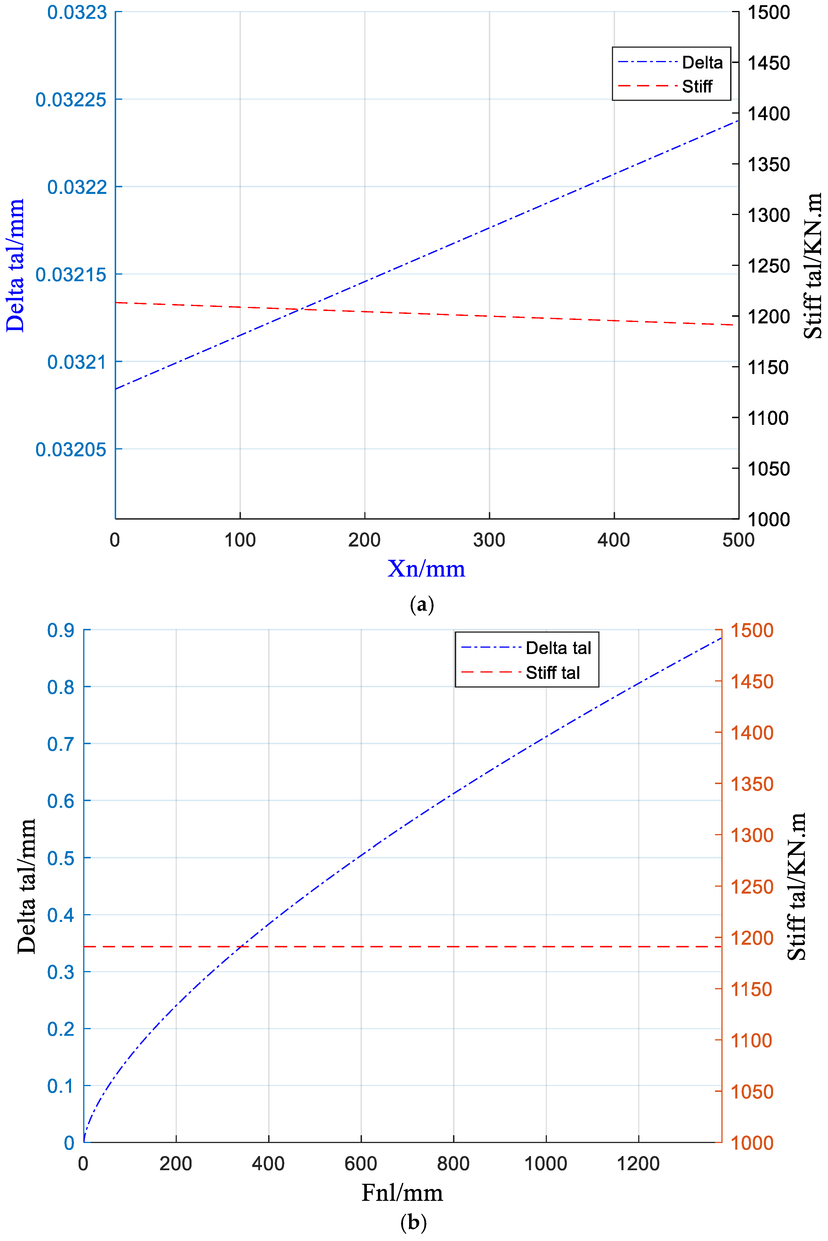
The characteristic curves of the stiffness and dynamic errors of the rigid–flexible deformations corresponding to different displacements and loads during DDSEC-TPS feed operation are shown in Figure 5. With the change in feed displacement within a range of stroke range and rated load, the stiffness of the mechanical transmission part of the DDSEC remains essentially constant. However, the maximum dynamic errors for rigid–flexible deformation are 0.32 and 0.4 mm, respectively.

4. Dynamic Error Compensation Control of DDSEC-TPS

Rigid–flexible deformation and nonlinear friction disturbance of the DDSEC-TPS can easily induce dynamic errors and compromise the positioning accuracy and dynamic performance. To suppress or eliminate the dynamic errors generated by the system affecting the accuracy of the pose motion of the parallel motion platform, the IBAS-BPNN algorithm is used to introduce dynamic error observation into the compensation control of the given displacement.

4.1. Dynamic Error Observation of DDSEC-TPS Based on IBAS-BPNN

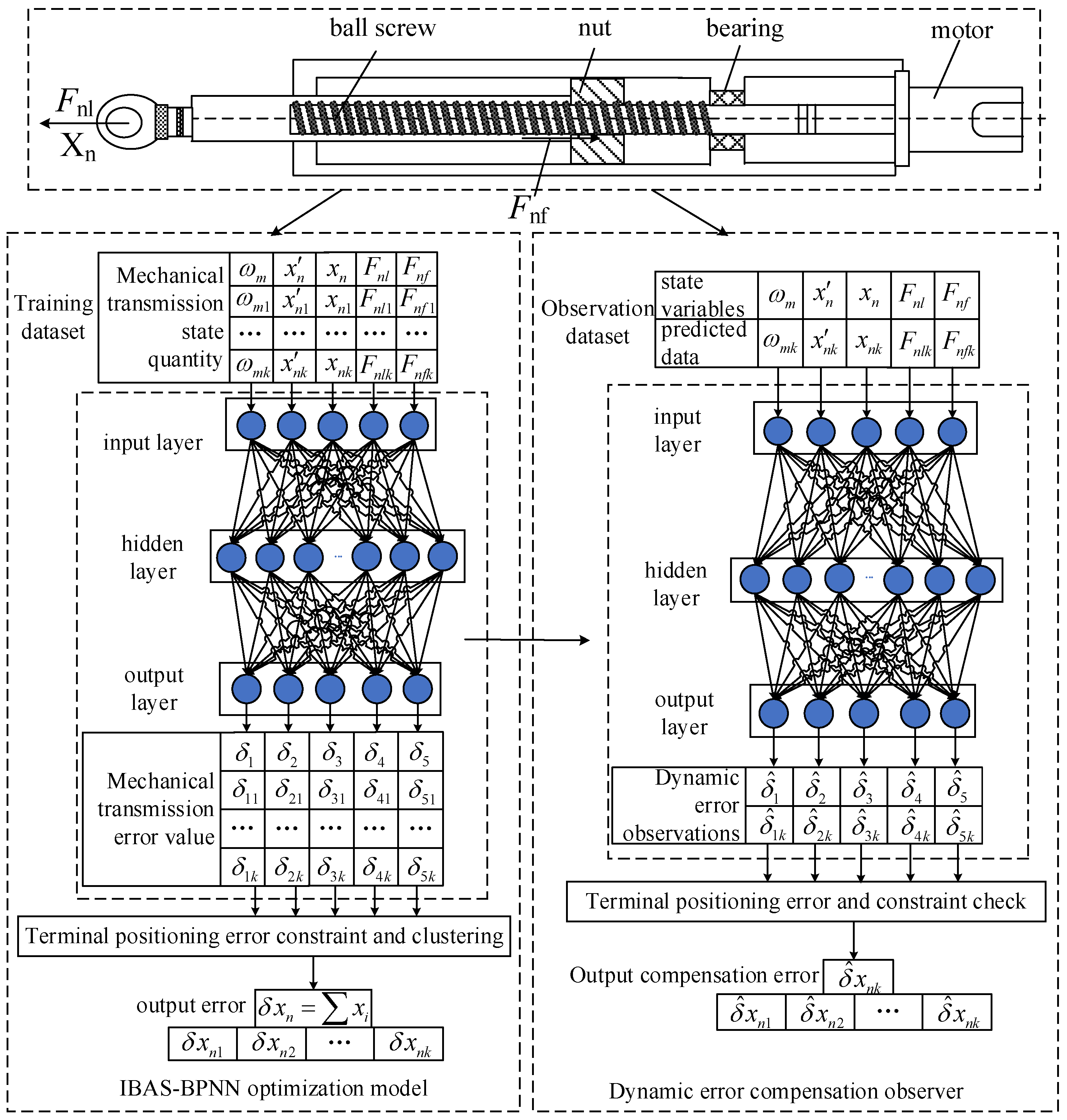
The IBAS-BPNN dynamic error observation of the DDSEC-TPS primarily consists of the dynamic error prediction model (A) and dynamic error observation (B), as shown in Figure 6.

4.1.1. BP Neural Network of DDSEC-TPS

The backpropagation neural network is a network structure based on the multi-layer forward, distributed, and parallel information computation of the neuron transfer function and the nonlinear mapping function of the error reverse adjustment of each layer’s weights and thresholds to predict the data. In part A of Figure 6, the DDSEC-TPS trains and verifies the BPNN prediction model with the dynamic error dataset of rigid–flexible deformations corresponding to the motor angular speeds, nut speeds, displacements, and load forces within the given displacement range to observe the dynamic error displacement of rigid–flexible deformations.
The observation structure of the dynamic error is divided into input, hidden, and output layers. The hidden and output layers contain the neurons and their net activation. The input of the k th node of the forward propagation hidden layer is as follows:
N e t h i k , i = k = 1 n W h k , i x h k , i θ h k , i
The output of the k th node of the hidden layer is as follows:
N e t h o k , i = f h a v , i ( k = 1 n W h k , i x h k , i + θ h k , i )  
The input to the k th node of the output layer is as follows:
N e t o i k = k = 1 q w k , i [ f h a v , i ( k = 1 n W h k , i x h k , i + θ h k , i ) ] + a k , i
The output of the k th node of the output layer is as follows:
N e t o o k = f o a v , i [ k = 1 q w k , i [ f h a v , i ( k = 1 n W h k , i x h k , i + θ h k , i ) ] + a k , i ]
where N e t k and x k denote the net activation of the k th neuron in this layer and the input value of the neuron, respectively. Furthermore, W k and θ k denote the weight and threshold values of the neuron, respectively.
The total error criterion function of each sample in the system is as follows:
E x n = 1 2 p = 1 p k = 1 l ( T k p N e t o o k , i p ) 2
During the backpropagation phase of dynamic error observation, the output error of each neuron layer is computed, starting from the output layer. Then, the weights and thresholds of each layer are adjusted using the error gradient descent method. This iterative process ensures that the final output of the modified network converges toward the desired value.
The weight update formula for the output layer is derived through gradient descent optimization, expressed as follows:
Δ w o k , i = η i E x n , i w k i = η i p = 1 p k = 1 l ( T k , i p N e t o o k , i p ) f o a v , i ( N e t o i k , i ) y i
The threshold adjustment formula of the output layer is as follows:
Δ a o k , i = η i E x n , i a o k , i = η i p = 1 p k = 1 l ( T k , i p N e t o o k , i p ) f o a v , i ( N e t o i k , i )
The weight adjustment formula of the hidden layer is as follows:
  Δ w h j , i = η i E x n , i w i j = η i p = 1 p k = 1 l ( T k p N e t o o k , i p ) f o a v , i ( N e t o i k , i ) w k i f h a v , i ( N e t h o k , i ) x j
The threshold adjustment formula of the hidden layer is as follows:
Δ θ i = η i E x n , i θ i = η i p = 1 p k = 1 l ( T k p N e t o o k k p ) f o a v , i ( N e t o i k , i ) · w k i f h a v , i ( N e t h o k , i )
The DDSEC-TPS employs the global loss function of the BPNN channels to adaptively monitor and record the dynamic error intensity between the forward channels. The mechanism enables real-time error adjustments, thereby enhancing system precision and stability.

4.1.2. IBAS-BPNN Algorithm

The initial weights and thresholds of a BPNN are generally obtained via random initialization, which can easily result in local optimization and saturation. The IBAS algorithm is an intelligent optimization algorithm with the advantages of a small number of computations, fast convergence, strong global optimization ability, and easy implementation. Consequently, the dynamic error observation performance of BPNN is enhanced by integrating the IBAS algorithm, which enables rapid optimization of the initial weights and thresholds during network training.
The activation function of IBAS-BPNN is as follows:
f a v , i ( k = 1 5 δ k , i , k = 1 5 c k , i ) = exp ( | | δ k , i c k , i | | 2 2 σ 2 )
where c k denotes the k th neuron center point, σ denotes the variance of the Gaussian function, and | | δ k c k | | denotes the Euclidean distance from the sample x k to the center point c k .
By quickly searching with the IBAS algorithm, the connection weights of the BP neural network are optimized for state variables of the DDSEC-TPS, such as motor angular speed, displacement speed, displacement, load force, friction force, and dynamic error. Optimizing the connection weights can yield the globally optimal network weights. The distance between the two antennae is set as d 0 , and the step size is step. Assuming that the initial space coordinate of the beetle is X 0 = ( x 1 , x 2 , . . . , x k ) , a random vector, i.e., b = rand ( k , 1 ) , is generated and normalized. Then, the space coordinates of the beetle’s left and right antennae are established.
X l , i = X i + b i d 0 , i / 2 X r , i = X i - b i d 0 , i / 2
where d 0 / 2 denotes the distance between the center of mass of the beetle and the antennae.
The updated location is as follows:
X t + 1 , i = X t , i δ t , i b i s i g n [ f ( X l , i ) f ( X r , i ) ]
where f ( X l ) and f ( X r ) denote the fitness values, and δ t denotes the step size of the t th iteration. The updated formula for the initial step size is as follows:
δ t , i = δ s t a r t , i δ s t a r t , i δ e n d , i e T t
where δ s t a r t denotes the initial step size of the beetle, δ e n d denotes the step size at the end of the iteration, and T denotes the maximum number of iterations.

4.1.3. Loss Function

The loss function is as follows:
min 1 N i j = 1 N L ( y j , f ( x ) ) + λ J ( f )
where 1 N i denotes the normalization factor, j = 1 N L ( y j , f ( x ) ) denotes the loss function of all samples, λ denotes the regularization coefficient, and J ( f ) denotes the complexity of the model.

4.2. Error Compensation Control of DDSEC-TPS

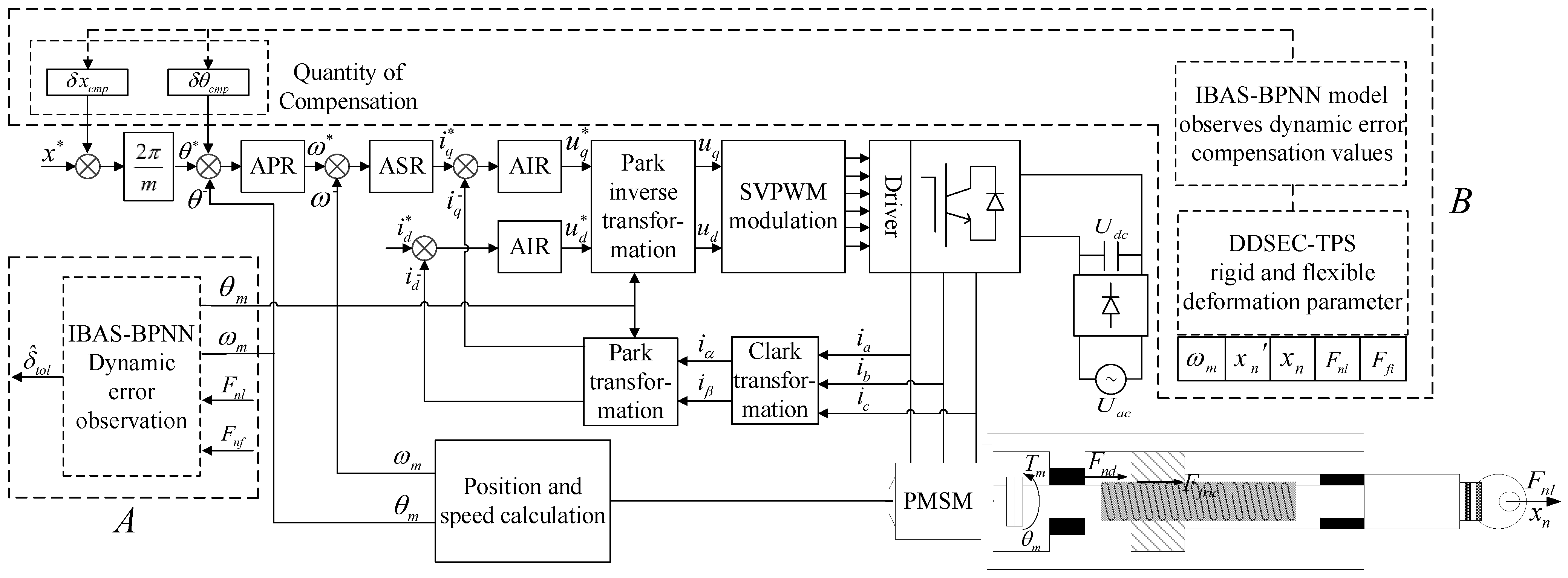
The structure of dynamic error compensation control of the DDSEC-TPS is illustrated in Figure 7. Through the state variables of the end positioning system, namely, ω m , x n , and x n , and load variables f n l , the observed dynamic error δ ^ t o l of the dynamic error prediction model is fed back to the target compensation position x n c m p * of the DDSEC. This enables real-time error correction in the DDSEC-TPS. The system implements dynamic error tracking control through vector control of the current, speed, and position loops.
As shown in modules A and B in Figure 7, the IBAS-BPNN dynamic error observer derives its inputs from the PMSM angular velocity and position data detected by the photoelectric encoder and current sensor measurements. Following weight optimization via the IBAS algorithm, the network model is refined via error backpropagation to approximate the true system dynamics from training samples. Thus, the input state variable space neuron response is realized, and the optimized dynamic error observation value is output through the network model, as shown in part B of Figure 6. The equivalent formula for the dynamic error observation is as follows:
δ ^ c m p , i = f a v o p t , i ( j = 1 N W o p t j , i x j , i + b o p t j , i )
where f a v o p t denotes the equivalent observation activation function of the dynamic error after DDSEC-TPS optimization, and W o p t and b o p t denote the equivalent optimization weights and thresholds of the IBAS-BPNN prediction models, respectively.
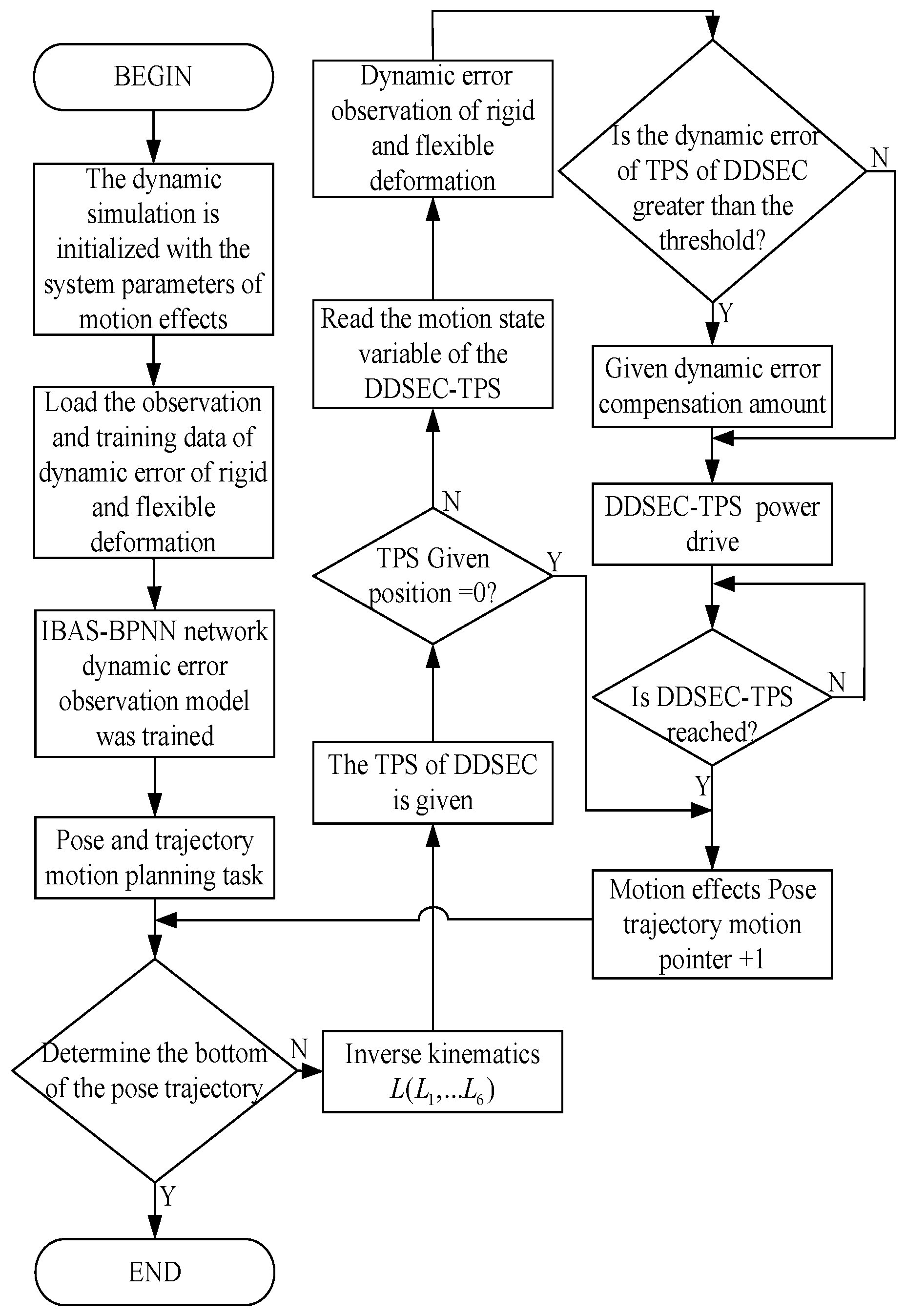
The IBAS-BPNN prediction model is used to obtain the eigenvalues for the dynamic error observation channel of the DDSEC-TPS, and a new set of optimized eigenvalues are obtained through the BPNN reverse channel. The compensation control process is illustrated in Figure 8. The IBAS-BPNN dynamic error compensation observation value δ ^ t o l is calculated according to Equation (41) within the time interval of k T , and the given value of the end positioning is revised as follows:
x n * ( k + 1 ) = x n * ( k ) + δ ^ c m p ( k )
In position control mode, the running direction polarity signal and rotation angular displacement pulse train are transmitted to the servo driver’s register and deviation counter, to enable precise control of the PMSM angular velocity and displacement. When the control pulse instruction of the input counter stops sending, the given values of the terminal positioning and pulse angular displacement of the dynamic error compensation saved in the reversible counter are reduced to zero, and the compensation position given by the DDSEC-TPS is completed when the motor stops rotating.

5. Experimental Test of Dynamic Error Compensation of DDSEC-TPS

The experimental testing of the dynamic error compensation control of the DDSEC-TPS was systematically evaluated under the conditions of rated load, as well as different inclination angles and displacements. It included the dynamic error compensation of the DDSEC-TPS observed using the data-driven IBAS-BPNN prediction model, the length and error of the terminal positioning before and after the dynamic error compensation control, and the influence of the dynamic error compensation control on the pose change in the parallel moving platform.

5.1. Experimental Platform of DDSEC-TPS

The experimental platform of the DDSEC-TPS, as shown in Figure 9a, comprises an adjustable angle-tilting platform, a DDSEC-TPS, and a load. The test principle is illustrated in Figure 9b. The motion state of the actuator of the parallel motion platform was simulated by adjusting the adjustable angle-tilting platform and stretching movement of the DDSEC-TPS. The parameters of the experimental test platform for the DDSEC-TPS are enumerated in Table 1.

5.2. Experimental Test of Dynamic Error Compensation Control of DDSEC-TPS Corresponding to Rated Load, Variable Tilting Angle, and Feed Displacement

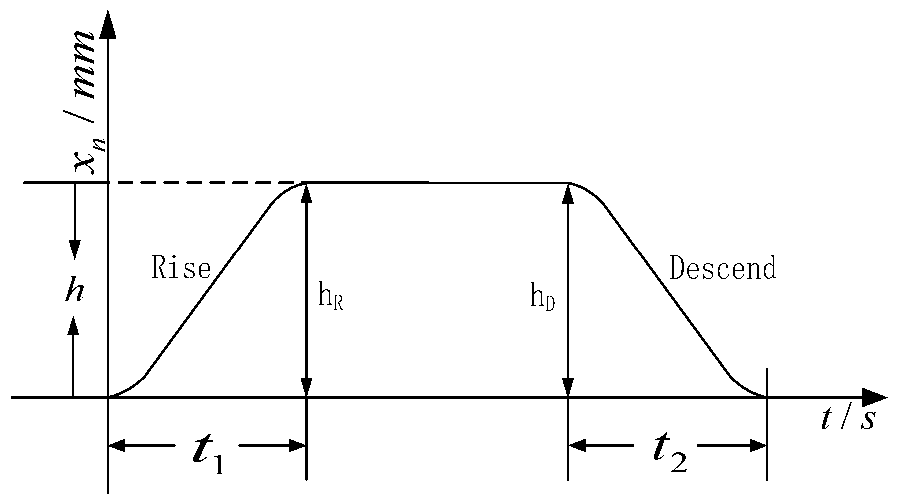
Using dynamic simulation of the parallel platform’s workspace motion, this study aimed to replicate the specified telescopic length of the DDSEC-TPS under varying loads and tilt angles. The stretching motion is illustrated in Figure 10. The actuator’s motion trajectory is dynamically tracked by adjusting the tilt angle, time, and terminal positioning command in position-control mode following a single-cycle saddle-shaped trajectory.
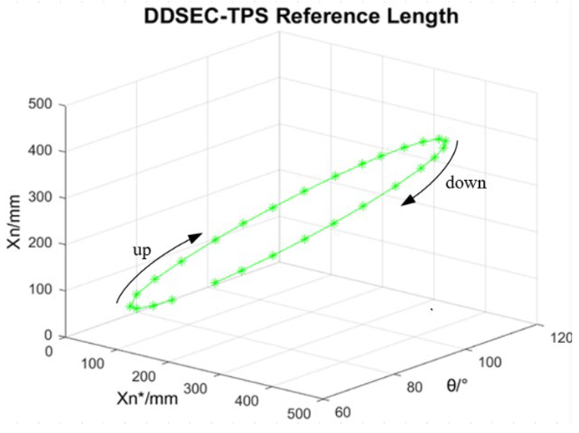
The elongation motion of the DDSEC-TPS was characterized by increasing the terminal positioning length from 0 mm to 450 mm, corresponding to a variation range of the tilting angle of 90° → 60° → 90°. Furthermore, the contraction motion of the DDSEC-TPS was characterized by a reduction in the terminal positioning length from 450 mm to 0 mm, corresponding to a variation range of the tilting angle of 90° → 120° → 90°. The terminal positioning length of the DDSEC-TPS is illustrated in Figure 11. According to the operating mechanism of the DDSEC-TPS, the terminal positioning length was measured by the grating scale, and opposite and mixed test datasets of elongation and contraction motion positioning lengths were constructed to train and verify the IBAS-BPNN model to observe the dynamic error compensation quantities.

5.2.1. Dynamic Error Observation of the Prediction Model Driven by Opposite Datasets

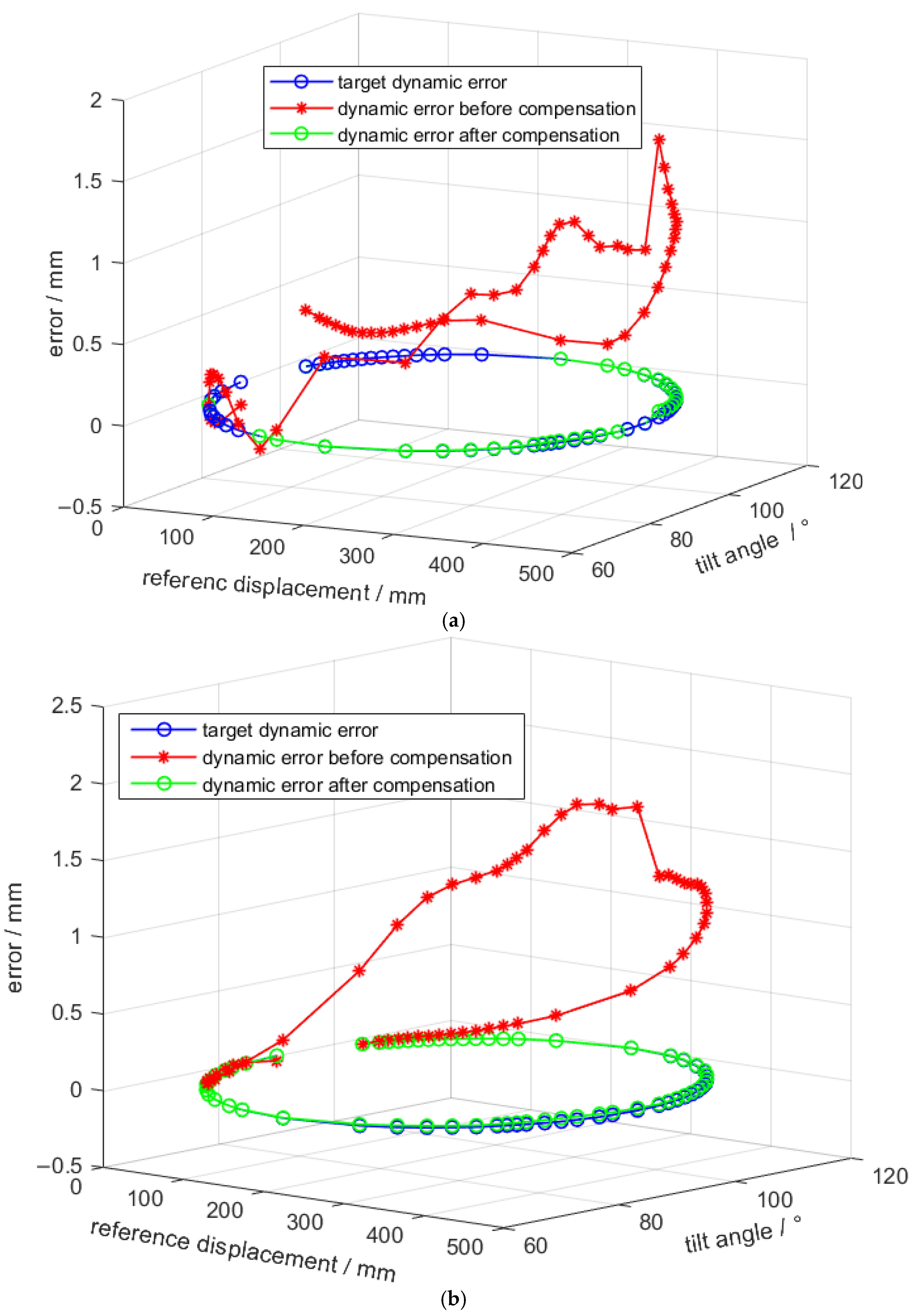
Training and validation were performed using the opposite datasets of extension motion positioning length and contraction motion positioning length. Furthermore, to enhance the error analysis, an error observation model of the DDSEC-TPS based on the positioning prediction length and an error observation model based on the contraction motion predicted length error driven by opposite datasets were established. Subsequently, dynamic error compensation was obtained through the dynamic error observer driven by the opposite data of the DDSEC-TPS. The dynamic errors of the DDSEC-TPS obtained using the error prediction model based on the positioning length and the length error of the extension motion are shown in Figure 12a,b, respectively.
As shown in Figure 12a,b, the dynamic error can be more accurately approximated to the target error value when using the error prediction models based on positioning length and positioning length error for observation and compensation. Notably, the model leveraging positioning length error demonstrates slightly superior dynamic error observation and compensation performance compared to the model based solely on length prediction. Furthermore, the dynamic errors associated with the elongation and contraction motions of the DDSEC-TPS reveal varying degrees of step phenomena.

5.2.2. Dynamic Error Observation of Prediction Model Driven by the Mixed Data

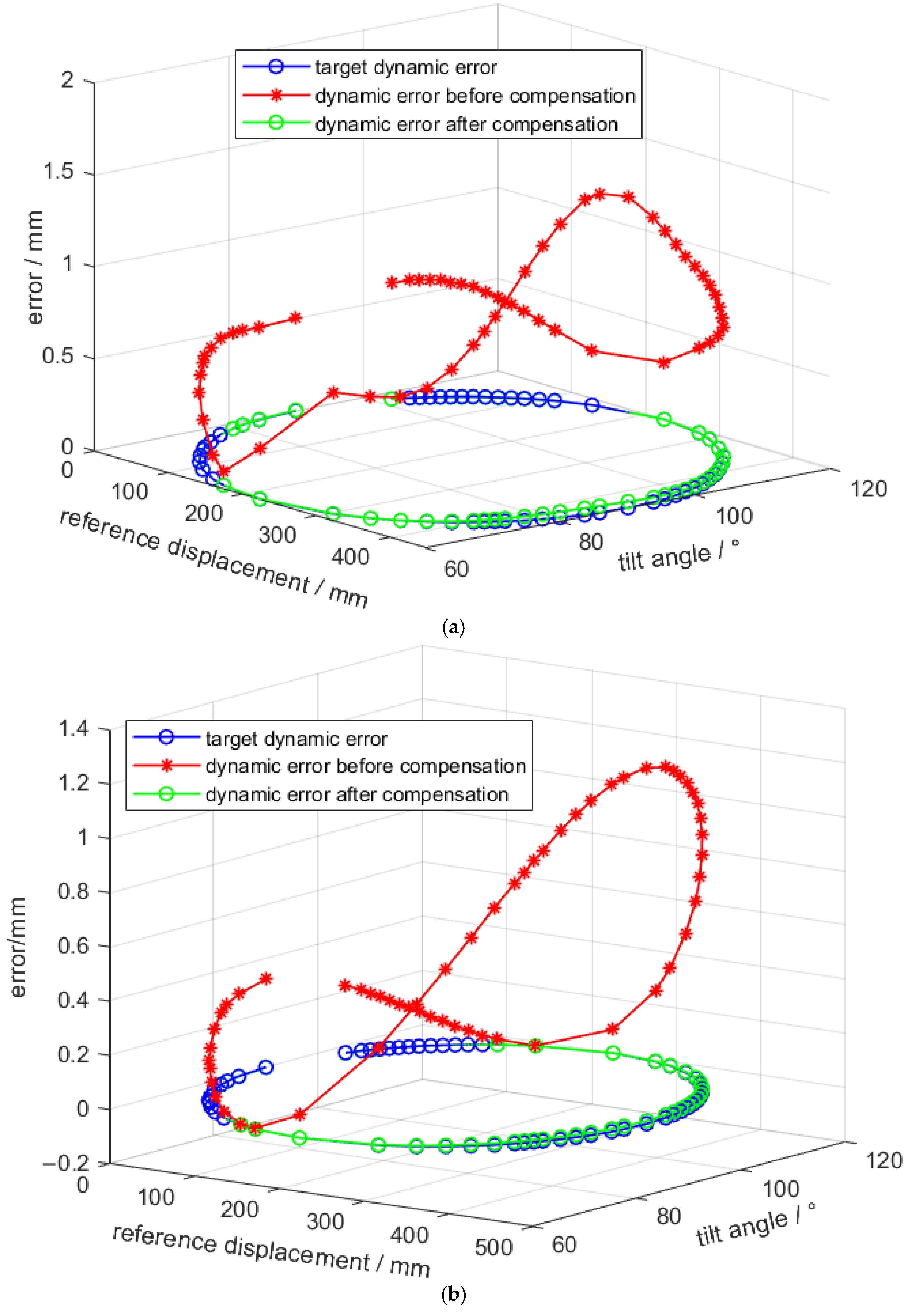
The dynamical error observation models were established for the DDSEC-TPS based on the prediction length and length error of telescopic motion positioning, respectively, using the positioning length datasets of elongation motion and contraction motion for training and verification. Dynamic error compensation was then realized by a dynamic error observer driven by mixed data from the DDSEC-TPS. The dynamic errors of the DDSEC-TPS observed by the error prediction model based on the positioning length and length errors of the telescopic motion are shown in Figure 13a,b.
Similarly, from a comparison of Figure 13a,b, it can be observed that the dynamic error can be better approximated to the target error value after the error prediction models of positioning length and positioning length error are used to observe and compensate for the dynamic error. In terms of its performance, the dynamic error observation compensation control performance of the error prediction model of the positioning length error is slightly better than that of the length prediction model. In addition, the dynamic errors of the elongation and contraction joints of the DDSEC-TPS exhibited different degrees of transitional continuous consistency.

5.2.3. Evaluation of Dynamic Error Observation

The mean squared error (MSE), root mean squared error (RMSE), and mean absolute percentage error (MAPE) were used to evaluate the dynamic error observation results obtained by the error prediction model for the positioning length and length error of telescopic motion driven by the opposite and mixed datasets. The evaluation results of the dynamic error observations are presented in Table 2. The MSE, RMSE, and MAPE of the dynamic error observation compensation control were significantly improved after dynamic error compensation control, and the comprehensive evaluation indices of the error prediction model driven by the mixed datasets were the best after compensation.

5.2.4. Terminal Positioning Tracking Performance of Dynamic Error Compensation Control

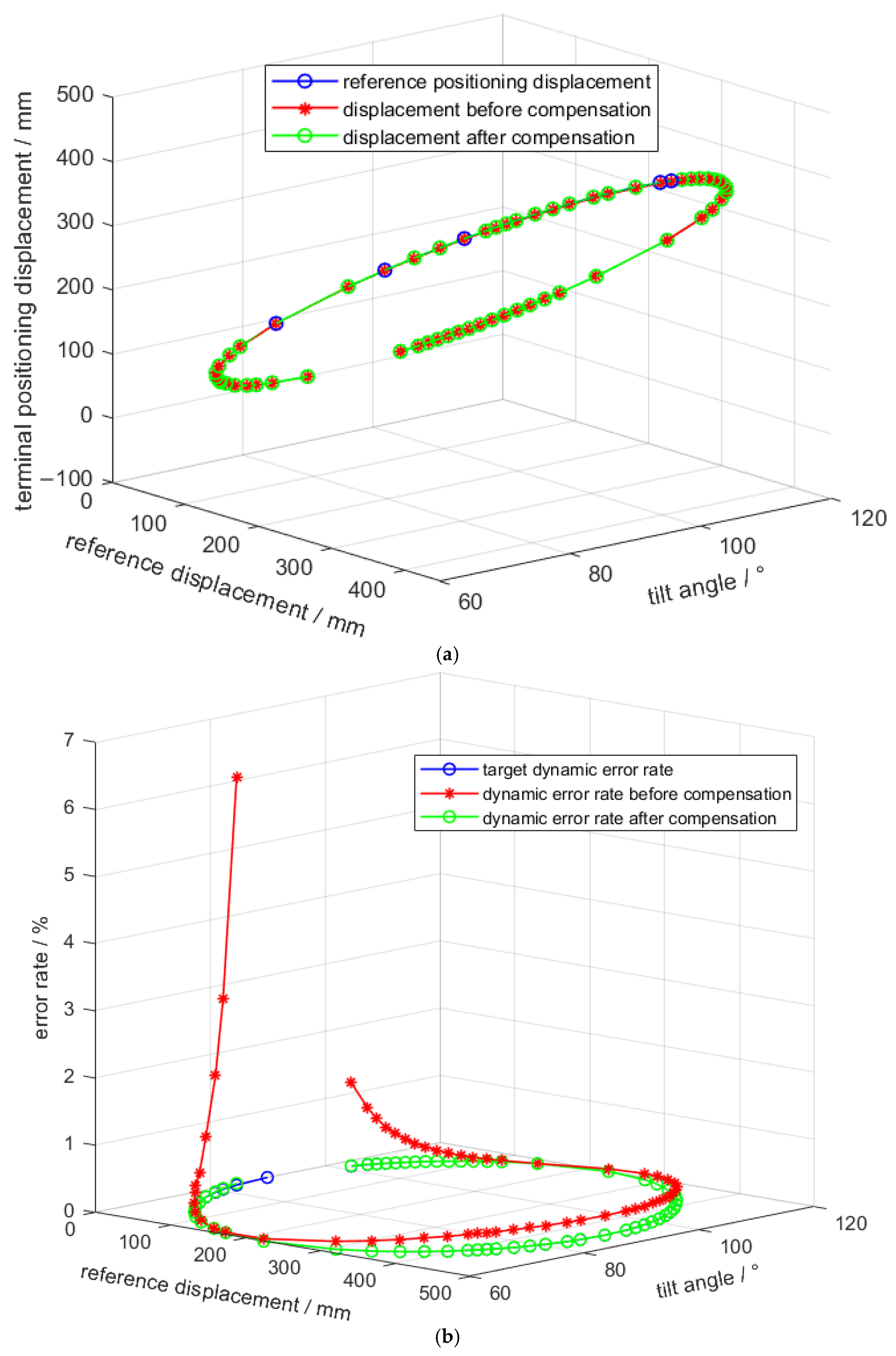
Based on using the error prediction model driven by mixed datasets as the dynamic error observer, the value of the observed dynamic error was used for the compensation control under a given terminal positioning length. The terminal positioning tracking performance of the DDSEC-TPS is shown in Figure 14. The dynamic error increases with an increase in the tilting angle and terminal positioning length under the rated load. The experimental test result after dynamic error compensation shows that the maximum compensation amount of the DDSEC-TPS is 1.5 mm, as shown in Figure 14a, and the maximum MAPE index is reduced by 21%, as shown in Figure 14b. The test results of the terminal positioning length are closer to the reference value and have better consistency after compensation. Therefore, dynamic error observation compensation control driven by mixed datasets can significantly improve the DDSEC’s terminal positioning tracking performance.

5.3. Pose Performance of Parallel Motion Platform After Dynamic Error Compensation

As shown in Figure 1, the pose motion trajectory of the 6-DOF parallel motion platform is realized by the telescopic motion of the six DDSEC power drivers. The parameters of the motion platform are specified in Table 3.
The dynamic error of the DDSEC feed motion affects the pose motion trajectory accuracy of the parallel motion platform. Consequently, it affects the fidelity of the motion special effect dynamic simulation of the motion. Under the conditions of rated load and different terminal positioning lengths, the influence of multiple DDSEC-TPSs dynamic error compensation control on the pose trajectory performance of the parallel motion platform was further verified, using the parameters of the parallel moving platform given below.
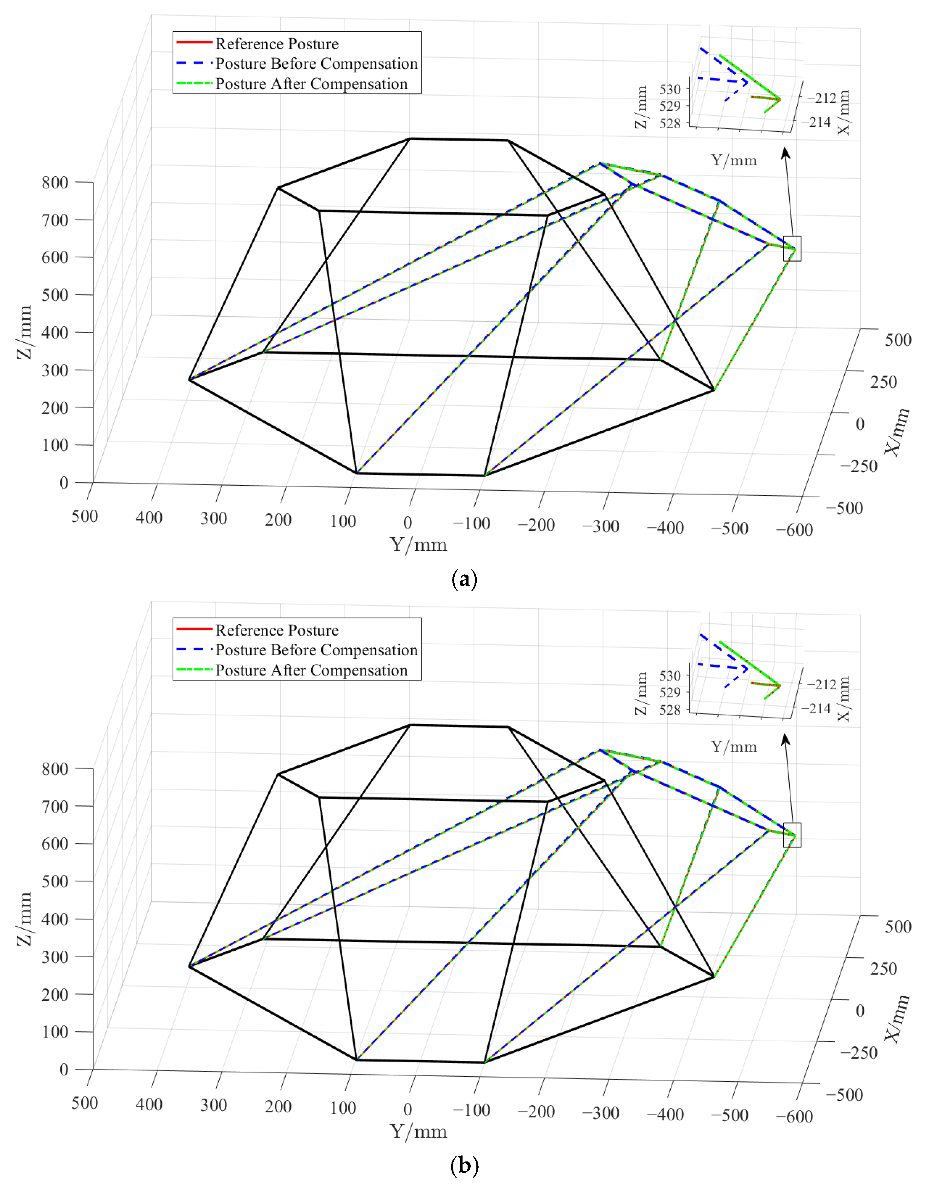
The pose motion trajectory in the working space of the parallel motion platform was obtained using the positive solution algorithm for the six given terminal positioning lengths. Table 4 lists the six terminal positioning lengths and the input values of the positive solution algorithm before and after dynamic error compensation control. Furthermore, the pose changes in the parallel motion platform were solved as shown in Figure 15. It can be observed from Figure 15 that the poses of the two groups of positive solutions after dynamic error compensation follow the reference positioning poses.
Before compensation of the parallel motion platform corresponding to the first set of DDSEC-TPSs, the position error is (−0.2109 mm, −2.4465 mm, and −2.4928 mm), and the attitude error is (0.0047°, 0.0052°, and 0.0067°). After compensation, the position error is (0.00074 mm, 0.0184.35 mm, and 0.0067 mm), and the attitude error is (0.000043°, 0.000043°, and 0.000057°). We can observe that the pose error is improved by (0.21016 mm, 2.4281 mm, and 2.4735mm) and (0.00466°, 0.00516°, and 0.00664°). Similarly, the pose error of set 2 improved by (0.1183 mm, 1.3899 mm, and 1.368 mm) and (0.00258°, 0.00219°, and 0.00398°). The accuracy and followability of the position and attitude motion corresponding to different given postural motion states can be better maintained through the dynamic error compensation control of DDSEC-TPS in the range of travel.

6. Conclusions

The parallel motion platform for dynamic simulation is a pose trajectory motion system with multi-DOF coordinated control. In view of the problem that DDSEC-TPSs are prone to produce cascaded coupling rigid–flexible deformation under the operating conditions of intermittent, reciprocating, and time-varying load, which affects the terminal positioning accuracy, the rigid–flexible deformation theory of mechanical transmission components was applied to establish a dynamic error compensation control method for DDSEC-TPSs based on IBAS-BPNN dynamic error observation. The conclusions are as follows:
(1)
Based on the theoretical analysis of the kinematics, dynamics, and pose errors of the parallel motion platform used in the dynamic simulation, it can be concluded that the pose errors of the parallel motion platform and DDSEC-TPS dynamic errors have an intrinsic correlation mapping relationship.
(2)
According to the cascaded coupling structure of the moving-link DDSEC-TPS, a dynamic error model of the DDSEC-TPS based on the rotor magnetic field orientation was established, and the dynamic errors of the rigid–flexible deformations of the mechanical transmission components were analyzed under the operating conditions of intermittent, reciprocating, and time-varying loads. The high-order, nonlinear, and multi-mode dynamic characteristics, as well as the dynamic error variation characteristic of rigid–flexible deformation, are shown.
(3)
A dynamic error observer for the DDSEC-TPS was established using the IBAS-BPNN prediction model to realize dynamic error compensation control. Under the conditions of rated load and different inclination angles, the IBAS-BPNN prediction model of length and length error was trained and verified using opposite and mixed datasets tested by the experimental platform, which helped effectively demonstrate the dynamic error and optimize the dynamic error observation model. The experimental results show that the maximum dynamic error can be reduced by 1.35 mm under the conditions of rated load and different tilt angles. that corresponding to the given length of the DDSEC-TPS of group 2, the parallel motion platform can minimize the pose errors to 0.017071 mm and 0.0000313°. The results further show that dynamic error compensation can improve the accuracy of the DDSEC-TPSs and the pose performance of the parallel motion platform.
(4)
Further studies should focus on the accuracy and consistency of the position and posture motion of the parallel motion platform and improve the fidelity of the dynamic simulation of the motion effects.

Author Contributions

Conceptualization, M.Z. and Q.Y.; methodology M.Z. and Q.Y.; software, M.Z.; validation, M.Z., L.L., Q.Y. and X.T.; formal analysis, M.Z. and Z.C.; investigation, M.Z.; resources, M.Z.; data curation, M.Z.; writing—original draft preparation, M.Z.; writing—review and editing, M.Z., L.L. and Q.Y.; visualization, M.Z.; supervision, Q.Y. and L.L.; project administration, M.Z. and L.L.; funding acquisition, L.L. and Q.Y. All authors have read and agreed to the published version of the manuscript.

Funding

This research was funded by the Ministry of Education’s Industry-University Cooperation and Collaborative Talent Cultivation Project grant number 241000782281306, 2410004232130821 And The APC was funded by 241000782281306, 2410004232130821.

Data Availability Statement

The research data is still being processed and also requires authorization from the cooperating party.

Acknowledgments

This work was supported in part by the National Natural Science Foundation of China under Grant 62173165, the Ministry of Education’s Industry-University Cooperation and Collaborative Talent Cultivation Project Grant 241000782281306, 2410004232130821, and the Modern Education Technology Research Project of Jiangsu Province under Grant 2021-R-91852.

Conflicts of Interest

The authors declare no conflict of interest.

References

  1. Miletović, I.; Pool, D.M.; Stroosma, O.; Van Paassen, M.M.; Chu, Q.P. Improved Stewart platform state estimation using inertial and actuator position measurements. Control Eng. Pract. 2017, 62, 102–115. [Google Scholar] [CrossRef][Green Version]
  2. Meng, Q.; Zhang, T.; He, J.; Song, J.; Chen, X. Improved model-based control of a six-degree-of-freedom Stewart platform driven by permanent magnet synchronous motors. Ind. Robot. 2012, 39, 47–56. [Google Scholar] [CrossRef]
  3. Becerra, V.M.; Belo, E.M. Dynamic Modeling of a Six Degree-of-Freedom Flight Simulator Motion Base. J. Comput. Nonlinear Dynam. 2015, 10, 193–204. [Google Scholar]
  4. Lee, S.M.; Xia, K.W.; Son, H.S. Robust Tracking Control of Spherical Motion Platform for Virtual Reality. IEEE Trans. Ind. Electron. 2021, 68, 892–901. [Google Scholar] [CrossRef]
  5. Wang, S.M.; Ehmann, K.F. Error Model and Accuracy Analysis of a Six-DOF Stewart Platform. J. Manuf. Sci. Eng. 2002, 124, 286–295. [Google Scholar] [CrossRef]
  6. Song, Y.B.; Tian, W.J.; Tian, Y.L.; Liu, X. Calibration of a Stewart platform by designing a robust joint compensator with artificial neural network. Precis. Eng. 2022, 77, 375–384. [Google Scholar] [CrossRef]
  7. Gonzalez, M.; Kacete, A.; Murienne, A.; Marchand, E. Light 6 DoF Network for robust and precise object pose estimation with small datasets. IEEE Robot. Autom. Lett. 2021, 6, 2914–2921. [Google Scholar] [CrossRef]
  8. Liu, T.M.; Shao, J.M.; Gao, J.Z.; Zhang, L.X. Servo system design of direct-drive aerospace linear electro-mechanical actuator. Proc. ITNEC 2016, 2016, 576–580. [Google Scholar]
  9. Deng, C.; Xie, S.Q.; Wu, J.; Shao, X.Y. Position error compensation of semi-closed loop servo system using support vector regression and fuzzy PID control. INT J. Adv. Manuf. Technol. 2014, 71, 887–898. [Google Scholar] [CrossRef]
  10. Liu, Y.G.; Gao, X.H.; Yang, X.W. Research of Control Strategy in the Large Electric Cylinder Position Servo System. Math. Probl. Eng. 2015, 2015, 167628. [Google Scholar] [CrossRef][Green Version]
  11. Li, D.Y.; Wang, J.Z. Nonsingular Fast Terminal Sliding Mode Control with Extended State Observer and Disturbance Compensation for Position Tracking of Electric Cylinder. Math. Probl. Eng. 2018, 2018, 1–12. [Google Scholar] [CrossRef]
  12. Henke, B.; Sawodny, O.; Neumann, R. Distributed Parameter Modeling of Flexible Ball Screw Drives Using Ritz Series Discretization. IEEE/ASME Trans. Mechatron. 2015, 20, 1226–1235. [Google Scholar] [CrossRef]
  13. Li, J.; Xie, F.G.; Liu, X.J.; Liu, D.W.; Li, F.H.; Jiang, Z. Dynamic Modeling of a Linear Feed Axis Considering the Characteristics of the Electro-mechanical and Rigid-flexible Coupling. J. Mech. Eng. 2017, 53, 60–69. [Google Scholar] [CrossRef]
  14. Kamalzadeh, A.; Gordon, D.J.; Erkorkmaz, K. Robust compensation of elastic deformations in ball screw drives. Int. J. Mach. Tools Manuf. 2010, 50, 559–574. [Google Scholar] [CrossRef]
  15. Guo, C.; Chen, L.P.; Ding, J.W. A novel dynamics model of ball-screw feed drives based on theoretical derivations and deep learning. Mech. Mach. Theroy 2019, 141, 196–212. [Google Scholar] [CrossRef]
  16. Xiang, H.B.; Wang, S.J.; Zhang, C.Q.; Li, X.F.; Liu, J. Compensation of Friction and Elastic Deformation for Ball Screw Drive System. In Proceedings of the 2015 IEEE International Conference on Mechatronics and Automation (ICMA), Beijing, China, 2–5 August 2015; Volume 2015, pp. 1031–1035. [Google Scholar]
  17. Dumanli, A.; Sencer, B. Data-driven iterative trajectory shaping for precision control of flexible feed drives. IEEE/ASME Trans. Mechatron. 2021, 26, 2735–2746. [Google Scholar] [CrossRef]
  18. Zhu, H.Z.; Fujimoto, H. Mechanical Deformation Analysis and High-Precision Control for Ball-Screw-Driven Stages. IEEE/ASME Trans. Mechatron. 2015, 20, 956–966. [Google Scholar] [CrossRef]
  19. Boyer, F.; Gotelli, A.; Tempel, P.; Lebastard, V.; Renda, F.; Briot, S. Implicit time integration simulation of robots with rigid bodies and Cosserat rods based on a Newton-Euler recursive algorithm. IEEE Trans. Robot. 2024, 40, 677–696. [Google Scholar] [CrossRef]
  20. Zhai, F.G.; Yin, Y.B.; Li, C.; Tian, W.; Qiao, Z. Stiffness modeling and feedforward control of servo electric cylinder drive system. J. Jilin Univ. (Eng. Technol. Ed.) 2021, 51, 443–449. [Google Scholar]
  21. Yang, M.; Ni, Q.; Liu, X.; Xu, D. Vibration Suppression and Over-Quadrant Error Mitigation Methods for a Ball-Screw Driven Servo System with Dual-Position Feedback. IEEE Access 2020, 8, 213758–213771. [Google Scholar] [CrossRef]
  22. Fujimoto, H.; Takemura, T. High-Precision Control of Ball-Screw-Driven Stage Based on Repetitive Control Using -Times Learning Filter. IEEE Trans. Ind. Electron. 2014, 61, 3694–3703. [Google Scholar] [CrossRef]
  23. Shirvani, H.K.; Hosseinkhani, Y.; Erkorkmaz, K. Suppression of Harmonic Positioning Errors in Ball-Screw Drives using Adaptive Feedforward Cancellation. Precis. Eng. 2021, 68, 235–255. [Google Scholar] [CrossRef]
  24. Vicente, D.A.; Hecker, R.L.; Villegas, F.J.; Flores, G.M. Modeling and vibration mode analysis of a ball screw drive. Int. J. Adv. Manuf. Technol. 2012, 58, 257–265. [Google Scholar] [CrossRef]
  25. Wang, G.; Zhan, H.; Zhang, G.; Gui, X.; Xu, D. Adaptive Compensation Method of Position Estimation Harmonic Error for EMF-Based Observer in Sensorless IPMSM Drives. IEEE Trans. Power Electron. 2014, 29, 3055–3064. [Google Scholar] [CrossRef]
  26. Zhang, C.Y.; Chen, Y.L. Tracking Control of Ball Screw Drives Using ADRC and Equivalent-Error-Model-Based Feedforward Control. IEEE Trans. Ind. Electron. 2016, 63, 7682–7692. [Google Scholar] [CrossRef]
  27. Kamalzadeh, A.; Erkorkmaz, K. Accurate tracking controller design for high-speed drives. Int. J. Mach. Tools Manuf. 2007, 47, 1393–1400. [Google Scholar] [CrossRef]
  28. Li, F.H.; Jiang, Y.; Li, T.M.; Ehmann, K.F. Compensation of Dynamic Mechanical Tracking Errors in Ball Screw Drives. Mechatronics 2018, 55, 27–37. [Google Scholar] [CrossRef]
  29. He, Z.Y.; Lian, B.B.; Li, Q.; Zhang, Y.; Song, Y.; Yang, Y.; Sun, T. An error identification and compensation method of a 6-DoF parallel kinematic machine. IEEE Access 2020, 8, 119038–119047. [Google Scholar] [CrossRef]
  30. Liu, Y.; Xu, L.; Zuo, L. Design, Modeling, Lab, and Field Tests of a Mechanical-Motion-Rectifier-Based Energy Harvester Using a Ball-Screw Mechanism. IEEE/ASME Trans. Mechatron. 2017, 22, 1933–1943. [Google Scholar] [CrossRef]
  31. Lv, Z.; Liu, P.; Ning, D.; Wang, S. Anti-Swaying Control Strategy of Ship-Mounted 3-RCU Parallel Platform Based on Dynamic Gravity Compensation. Machines 2024, 12, 209. [Google Scholar] [CrossRef]
  32. El-Sousy, F.F.M.; Amin, M.; Mohammed, O.A. High-Precision Adaptive Backstepping Optimal Control using RBFN for PMSM-Driven Linear Motion Stage. In Proceedings of the 2019 IEEE International Electric Machines & Drives Conference (IEMDC), San Diego, CA, USA, 12–15 May 2019; Volume 2019, pp. 1680–1687. [Google Scholar]
  33. Shen, H.; Zhou, H.; Jin, Y.; Li, L.; Deng, B.; Xu, J. Research on Pose Error Modeling and Compensation of Posture Adjustment Mechanism Based on WOA-RBF Neural Network. Machines 2024, 12, 782. [Google Scholar] [CrossRef]
  34. Li, Y.; Xue, Y.; Yang, F.; Cai, H.; Li, H. Comprehensive Compensation Method for Motion Trajectory Error of End-Effector of Cable-Driven Parallel Mechanism. Machines 2023, 11, 520. [Google Scholar] [CrossRef]
  35. Liu, J.; Chen, X. Adaptive control based on neural network and beetle antennae search algorithm for an active heave compensation system. Int. J. Control. Autom. Syst. 2022, 20, 515–525. [Google Scholar] [CrossRef]
  36. Zhou, Z.; Gao, J.; Zhang, L. Synchronization Control with Dynamics Compensation for Three-Axis Parallel Motion Platform. Actuators 2024, 13, 166. [Google Scholar] [CrossRef]
  37. Tang, G.; Lei, J.; Du, H.; Yao, B.; Zhu, W.; Hu, X. Proportional-integral-derivative controller optimization by particle swarm optimization and back propagation neural network for a parallel stabilized platform in marine operations. J. Ocean. Eng. Sci. 2025, 10, 1–10. [Google Scholar] [CrossRef]
  38. Zhao, M.; Wang, X.; Liu, L.; Tu, X.; Yang, Q. Optimization of PMSM for EV based on Vibration and Noise Suppression. Appl. Comput. Electrom. 2024, 39, 64–80. [Google Scholar] [CrossRef]
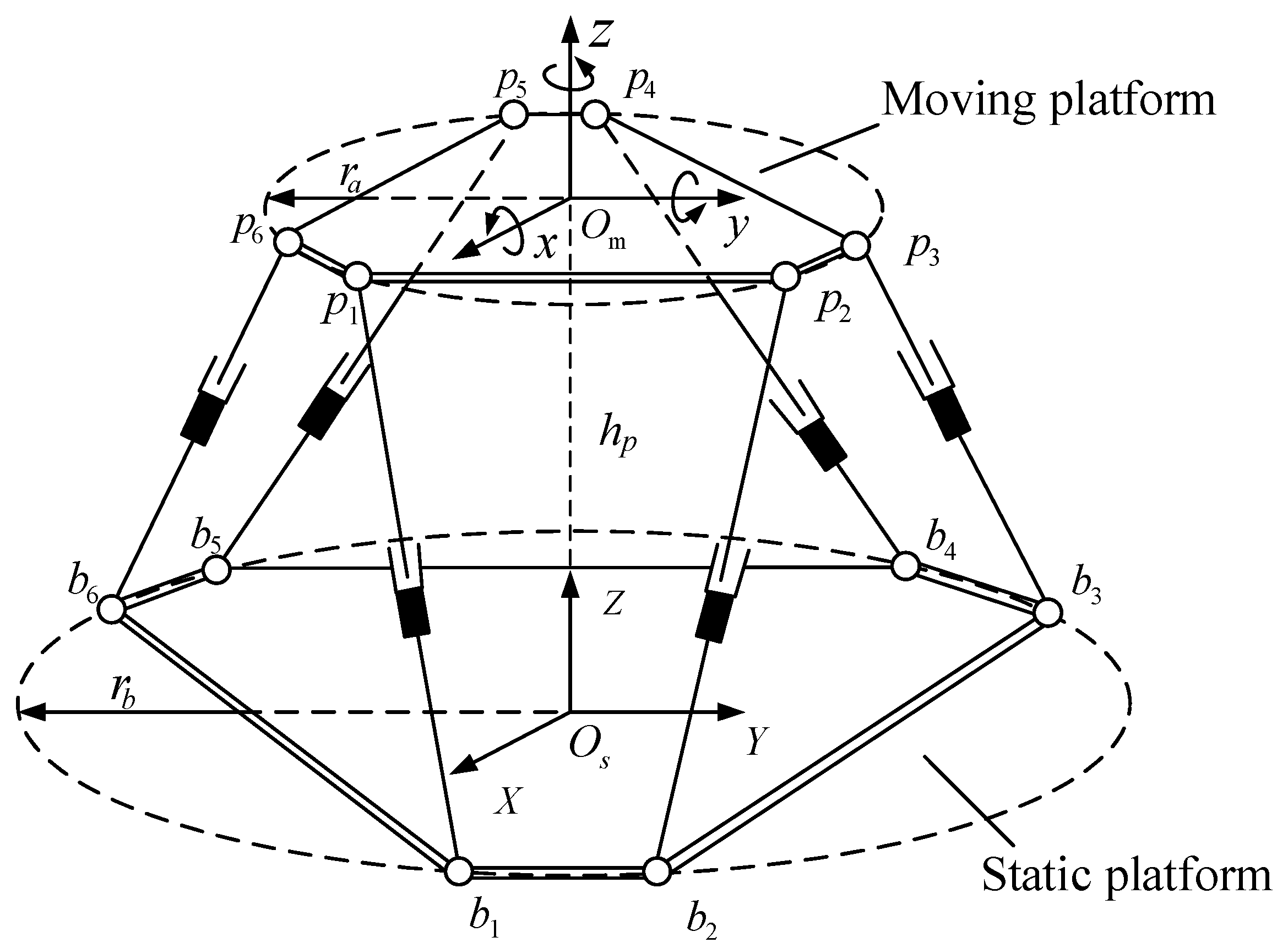
Figure 1. Six DOF parallel motion platform.
Actuators 14 00317 g001
Figure 2. Dynamical structure of parallel motion platform.
Actuators 14 00317 g002
Figure 3. Dynamical model of DDSEC-TPS. (a) DDSEC-TPS structure. (b) DDSEC-TPS schematic diagram.
Actuators 14 00317 g003
Figure 4. Actual operating state analysis of DDSEC-TPS. (a) Air-gap flux density of PMSM. (b) Harmonic response analysis of PMSM. (c) Vibration mode analysis of ball screwnut pair.
Actuators 14 00317 g004aActuators 14 00317 g004b
Figure 5. Dynamic error of rigid–flexible deformation of DDSEC-TPS. (a) Dynamic error within the range of rated load travel. (b) Dynamic error within the range of load variation.
Actuators 14 00317 g005
Figure 6. IBAS-BPNN dynamic error observation mode.
Actuators 14 00317 g006
Figure 7. Principle and structure of dynamic error compensation control of DDSEC-TPS. (A) Dynamic error observation. (B) Error compensation control.
Actuators 14 00317 g007
Figure 8. Dynamic error compensation control flow.
Actuators 14 00317 g008
Figure 9. DDSEC-TPS experimental platform. (a) Experimental platform. (b) Experimental testing principle.
Actuators 14 00317 g009
Figure 10. Realization of DDSEC-TPS telescopic motion.
Actuators 14 00317 g010
Figure 11. Feed length of DDSEC-TPS.
Actuators 14 00317 g011
Figure 12. Dynamic error observation driven by opposite data. (a) Length prediction model. (b) Length error prediction model.
Actuators 14 00317 g012
Figure 13. Dynamic error observation driven by mixed data. (a) Length prediction model. (b) Error prediction model.
Actuators 14 00317 g013
Figure 14. DDSEC-TPS location tracking performance. (a) Terminal positioning comparison. (b) Error rate.
Actuators 14 00317 g014
Figure 15. Position and pose changes in the parallel motion platform before and after compensation control. (a) Position and pose changes corresponding to set 1. (b) Position and pose changes corre-sponding to set 2.
Actuators 14 00317 g015
Table 1. Parameters of DDSEC-TPS’ platform.
NameSymbolsUnitsValue
Rated powerPeW400
Rated speednerpm3000
Rated velocityVemm/s250
Rated thrustFnlKN1.38
ItineraryLnmm500
Helical pitchLsmm5
Table 2. Evaluation results of dynamic error observation.
TypesDataset and Observation ModelMSERMSEMAPE
Before
compensation
Opposite data, length model1.17651.08472.0187
Mixed data, length model1.53511.23902.4307
Opposite data, error model1.13501.06541.9118
Mixed data, error model1.11021.05371.9184
After
compensation
Opposite data, length model8.1594 × 10−50.00903291.6965
Mixed data, length model0.000297160.0172381.6990
Opposite data, error model7.6153 × 10−50.00872661.6964
Mixed data, error model7.6055 × 10−50.0087211.696424
Table 3. Parameters of the parallel motion platform.
Platform ParametersSymbolsUnitsValues
Moving platform radius r a m 0.325
Static platform radius r b m 0.428
Short side center angle of the top platform α p ° 26.68
Short side center angle of the bottom platform α b ° 30.0
Height between platforms h m 596.0
Initial leg length l 0 m 0.60
Minimum leg length l m i n m 0.60
Maximum leg length l m a x m 1.05
Quality of the moving platform and load m k g 85.0
Upper leg quality m k g 13.0
Lower leg quality m k g 22.0
Table 4. Given the length of DDSEC-TPS under rated load.
Points GroupSymbolsUnitsGiven LengthBefore CompensationAfter Compensation
Set 1xn1mm646.3000646.6351646.3532
xn2mm612.9000613.1993612.6177
xn3mm653.7000653.3837643.4422
xn4mm733.5500732.8540733.5058
xn5mm736.8000736.0835737.0036
xn6mm646.7800647.3723647.1427
Set 2xn1mm690.0000690.1287690.0114
xn2mm755.5000755.6838755.5605
xn3mm781.4500780.7317781.4321
xn4mm603.5100603.2412603.5164
xn5mm623.4200622.3021623.3479
xn6mm608.1900608.2149608.3630
Disclaimer/Publisher’s Note: The statements, opinions and data contained in all publications are solely those of the individual author(s) and contributor(s) and not of MDPI and/or the editor(s). MDPI and/or the editor(s) disclaim responsibility for any injury to people or property resulting from any ideas, methods, instructions or products referred to in the content.