Article

Metal Thickness Measurement Using an Ultrasonic Probe with a Linear Actuator for a Magnet-Type Climbing Robot: Design and Development

1
School of Mechanical Engineering, Hangzhou Dianzi University, Hangzhou 310018, China
2
Ocean College, Zhejiang University, Zhoushan 316000, China
3
Zhejiang University Robotics Institute, Yuyao 315400, China
4
Haichuang Humanoid Robot Industry Innovation Center, Hangzhou 311100, China
*
Author to whom correspondence should be addressed.
Actuators 2025, 14(6), 299; https://doi.org/10.3390/act14060299
Submission received: 8 May 2025 / Revised: 5 June 2025 / Accepted: 13 June 2025 / Published: 18 June 2025
(This article belongs to the Special Issue Advanced Robots: Design, Control and Application—3rd Edition)

Abstract

The inspection of oil storage tanks is a critical measure to prevent the risk of oil leakage. Therefore, research has focused on magnet-type climbing robots for automated tank inspections. While existing magnet-type climbing robots have demonstrated significant improvements in climbing steel structures, their capability in terms of metal thickness measurement has not been previously evaluated. During thickness inspections, ultrasonic thickness sensors require a probe to be pressed against target surfaces. To automate metal thickness measurements, this pressing motion of the probe needs to be performed by the robot. This study introduces a novel metal thickness measurement device comprising an ultrasonic probe, a linear actuator, a gel pump, and a pressure sensor designed for a magnet-type climbing robot. The linear actuator moves the probe to its initial position, the gel pump injects a coupling gel, and then the actuator moves the probe to the surface and back. Finally, our prototype of an ultrasonic probe with a linear actuator was installed on a magnet-type climbing robot to demonstrate its functionality in a practical application regarding an oil storage tank inspection system. The prototype achieved a measurement success rate of 65.9% and an average error of 0.7% compared to a reference thickness. This article details the design and development of the ultrasonic probe with a linear actuator to enable the probe to make contact with the surface. It then details the experimental results and evaluation of metal thickness measurement performed using the prototype and the climbing robot.

1. Introduction

The inspection of oil storage tanks is a critical measure to prevent the risk of oil leakage. In recent years, the number of large structures, such as storage tanks, has increased with traffic volume [1]. For example, in China alone, there are 14,461 storage tanks [2]. The frequency of the routine cleaning and maintenance of these tanks has been increasing [3], and their inspection is a time-consuming task. Moreover, it is dangerous to perform this task manually [4], as workers often use temporary scaffolds [5] to reach high places. Although inspection is essential to prevent leaks and maintain operational safety, traditional inspections require technicians to climb scaffoldings or suspended platforms, exposing them to high-risk working conditions. Additionally, this requires significant time and financial resources. Therefore, many researchers have been developing various inspection robots to inspect structures easily and safely [6]. Climbing robots, which adhere to iron structures, are useful for inspecting facilities such as oil storage tanks [7].
The automation of inspections is expected to replace dangerous, time-consuming, and difficult tasks that humans currently perform. The inspection robots move through various environments and conduct a series of inspections under remote operation [8]. With the advancement of robotics, an increasing amount of work has been replaced by robots [9]. Climbing robots have been applied in various circumstances, such as welding, painting, and monitoring [10]. Adhesion methods are selected based on the material and shape of the target structures. Suction-type climbing robots use suction cups and vacuums to adhere to the surface. This method can be applied to any material with a sufficiently flat surface, making it suitable for applications such as inspecting aircraft bodies [11,12]. The method using propellers or fans can be applied to curved, rough, or non-ferromagnetic surfaces [13]. Therefore, propeller-type robots have been used to inspect concrete walls and pipes [14]. Magnet-type climbing robots demonstrate steady movement on steel objects [15]. They are used for the maintenance of storage tanks [16,17] and steel gates [18], as the walls of such tanks are made of ferromagnetic materials [19]. Robots that utilize permanent magnet adhesion can provide greater adhesion force, conserve energy, and mitigate the risk of falling [15,16]. Magnet-type climbing robots demonstrate excellent performance in high-load tasks, and performance analysis has confirmed their ability to adhere safely and operate stably [20].
The deformation of a large crude oil storage tank affects its safe operation, requiring metal thickness inspection for each part of the tank wall [21]. The metal thickness can be measured using an ultrasonic sensor. However, there are technical challenges to overcome to achieve thickness measurement using ultrasonic sensors operated by robots. Ultrasonic inspection requires the probe (transducer) to contact the target surface with appropriate force, ensuring the adequate coupling of the transmitted acoustic energy [22]. During metal thickness measurements using ultrasonic sensors, the robot must properly dispense a coupling gel and firmly press the probe against the measurement surface [23]. Therefore, an electric pusher [24], a solenoid [25], a legged robot [26], a four-bar linkage [23,27], and a Scotch Yoke mechanism [28] were used as actuators to make contact as summarized in Table 1. Using the electric pusher, the lifting and releasing motion of the probes was accomplished, and the robot—equipped with an ultrasonic sensor—performed weld inspections for spherical tanks [24]. In [26], a six-legged robot performed crouching motions to move a probe to a surface. Their robot successfully crouched down toward a horizontal flat steel surface; the average measurement error compared to the reference values was 2% for the 2 mm and 3 mm sample plates. However, the thickness of the oil tanks is generally 5 mm to 10 mm [29]. A probe that is controlled using a solenoid was tested on metal plates with thicknesses of 5 mm, 8 mm, and 10 mm in [25]. A module using the Scotch Yoke mechanism to push an ultrasonic probe to a surface for measurement is proposed in [28]. The Scotch Yoke mechanism can convert the rotational movement of the robot’s wheels into the pressing motion of the probe, allowing the robot to climb the surface without the need for additional actuators. However, these devices were designed for specific robot configurations and have not been widely adopted. In addition, to automate a metal thickness measurement, the coupling gel needs to be dispensed to facilitate the propagation of solid waves [23]. Therefore, an air compressor and a diaphragm pump were used to spray the coupling gel near a probe, assisting a robot in completing wall thickness detection using ultrasonic sensors [27]. Their robot achieved a maximum error of 0.2 mm, which fell within the allowable error range, on steel plates with thicknesses ranging from 5 mm to 8 mm. Yet, the air compressor and the diaphragm pump were not mounted on the robot due to payload limitations. In [23], a steel climbing robot integrated with an ultrasonic sensor was developed for autonomous thickness measurement of steel bridge members. In their study, a four-bar mechanism was designed to generate vertical movements for the ultrasonic transducer, allowing it to place a probe on a measurement surface. A peristaltic pump was mounted on the robot to dispense the coupling gel.
Existing magnet-type climbing robots have shown significant improvements in their climbing ability on steel-made structures; however, these robots have not been widely used in metal thickness measurement tasks, as they require probe contact and the application of coupling gel. In this study, we propose the use of a linear actuator as a new actuator for ultrasonic thickness measurements used by climbing robots. The magnet-type climbing robot moves stably on the tank surface; therefore, we selected magnetic adhesion as the primary method for our climbing robot. The key contribution of this study is the development of an oil storage tank inspection system utilizing a magnet-type climbing robot and an ultrasonic sensor for measuring metal thickness. The linear actuator enables the ultrasonic probe to make contact with the measurement surface. Moreover, a mounted peristaltic pump realizes the proper injection of the coupling gel. The developed prototype of the ultrasonic probe with the linear actuator was mounted on a climbing robot. The prototype achieved a measurement success rate of 65.9% and an average error of 0.7% compared to a reference thickness. The result showed an average error of 0.07 mm, which was within the allowable error range of 0.2 mm [27]. We believe that metal thickness measurement using an ultrasonic probe with a linear actuator and a peristaltic pump is a simple, yet potentially effective method. Furthermore, the design introduced in this study can be adapted for use on other industrial surfaces, such as ship hulls, bridges, or pipelines.
The remainder of this paper is organized as follows. In Section 2, the design and development of an ultrasonic probe with a linear actuator for metal thickness measurements are explained. Section 3 describes the experiment and the evaluation of metal thickness measurement by a magnet-type climbing robot using the prototype sensor probe with the actuator. Section 4 discusses the experimental results and the limitations of the study. Finally, Section 5 presents the conclusion of this paper and outlines future work.

2. Materials and Methods

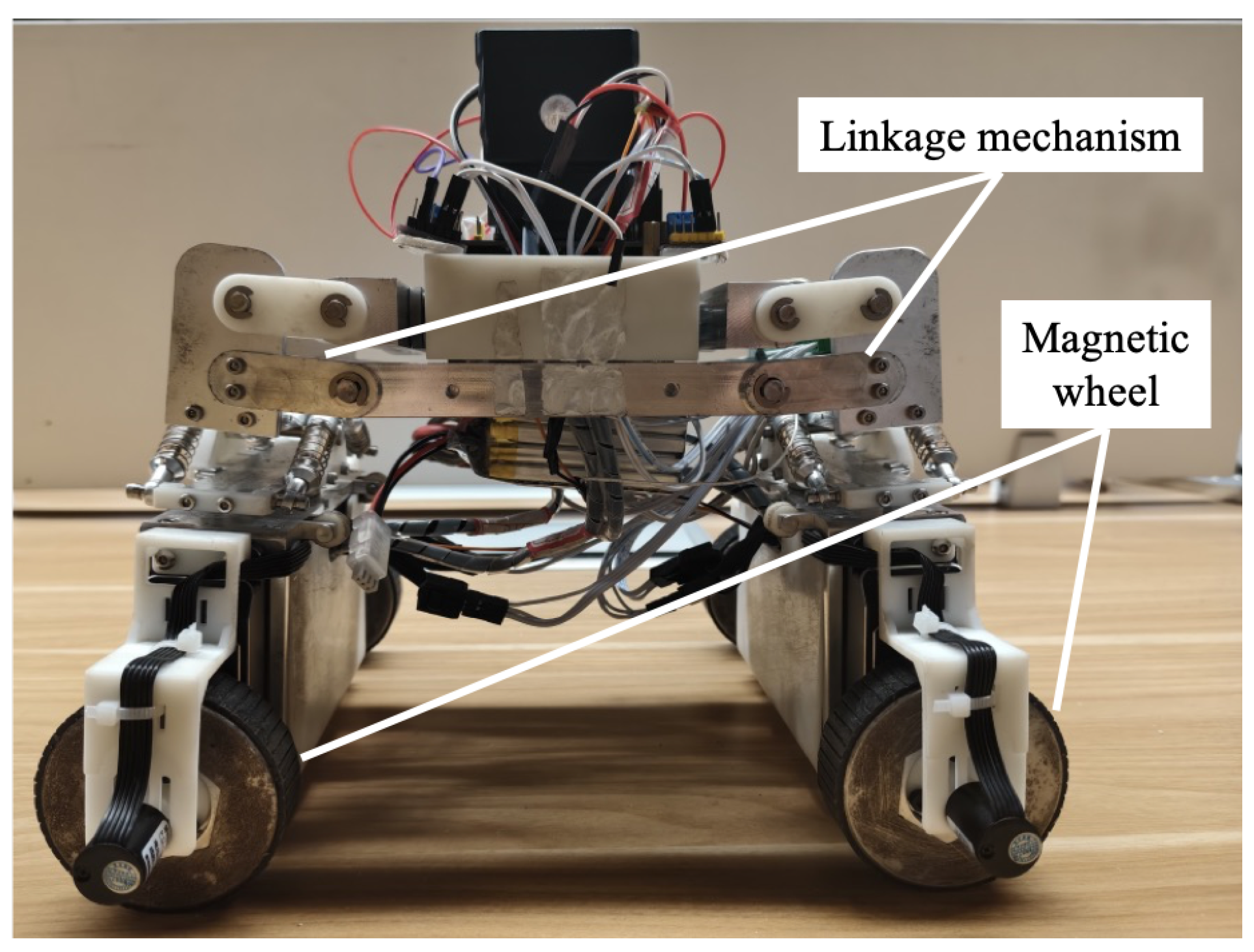
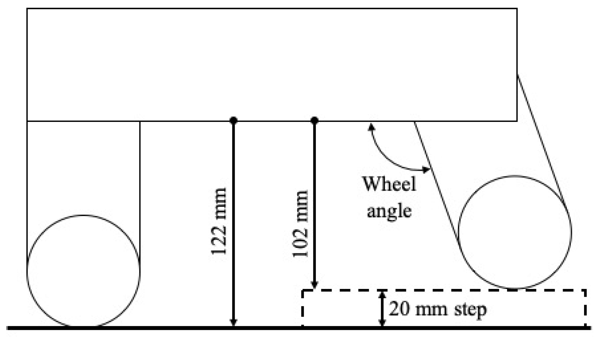
2.1. Magnet-Type Climbing Robot

The magnet-type climbing robot used in this study was previously presented in [30,31]. The robot uses four magnetic wheels and can traverse obstacles on steel-made structures, including 20 mm-high steps and concave and convex corners [31]. Table 2 shows the specification of the robot used in this study, and Figure 1 shows the side view of the magnet-type climbing robot. Four continuous-rotation servos were used to drive the magnetic wheels. The angle of the front and rear wheels to the surface can be adjusted to overcome steps as shown in Figure 2. An STM32-compatible board was used to control the robot, and communication between the robot and the controller handle was established via a Wi-Fi module. The robot was designed to operate for 50 min using a 2100 mAh Li-Po battery.

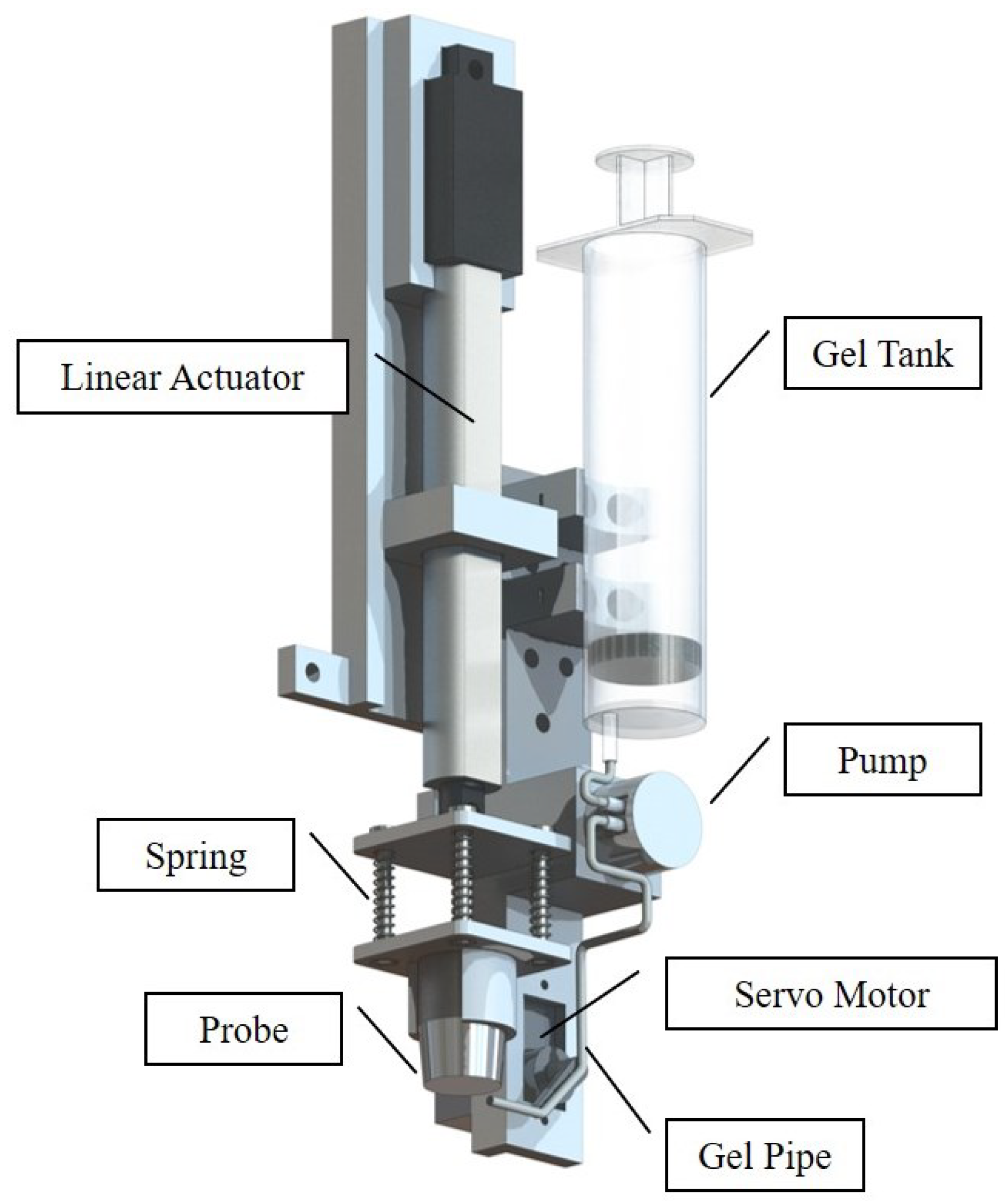
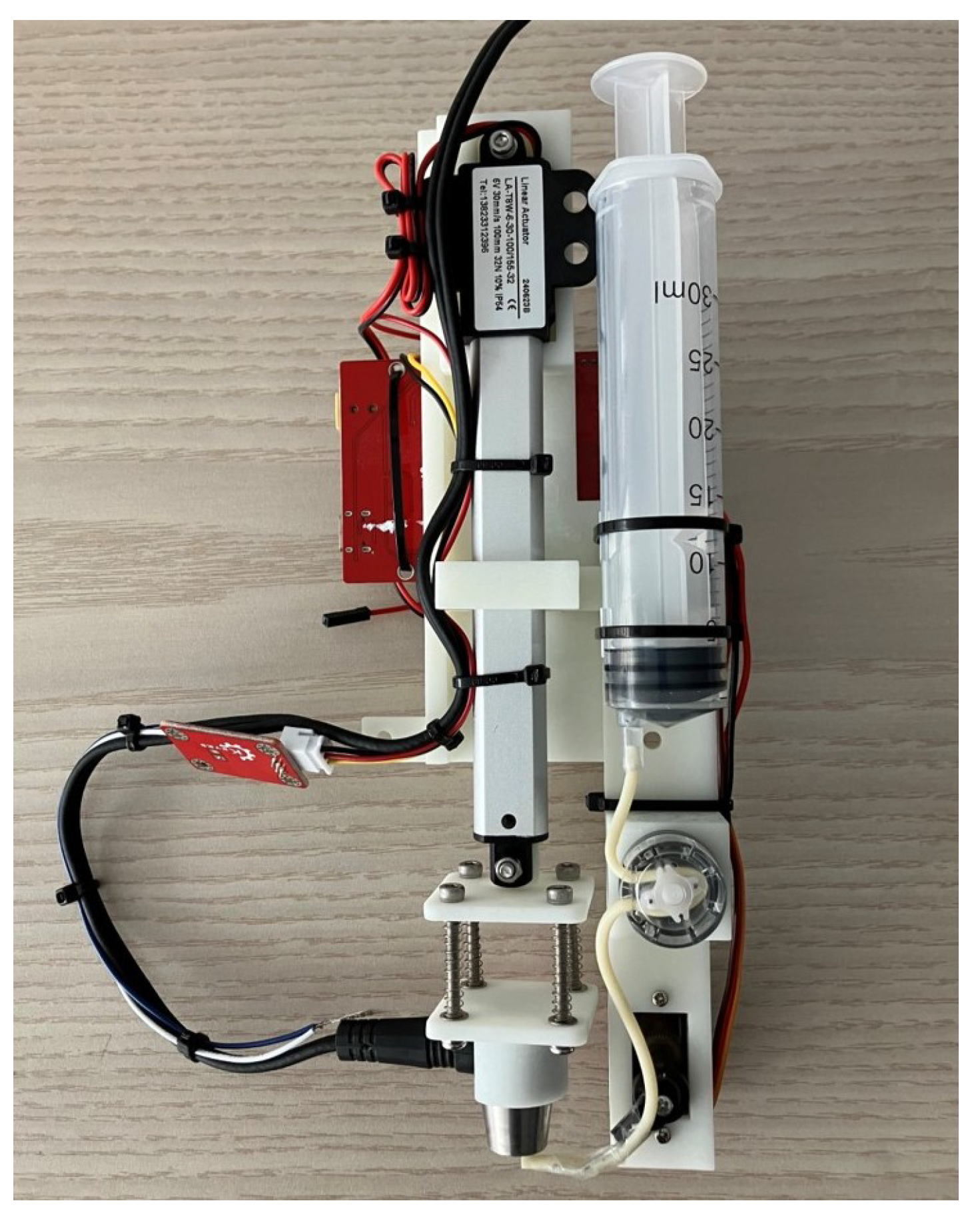
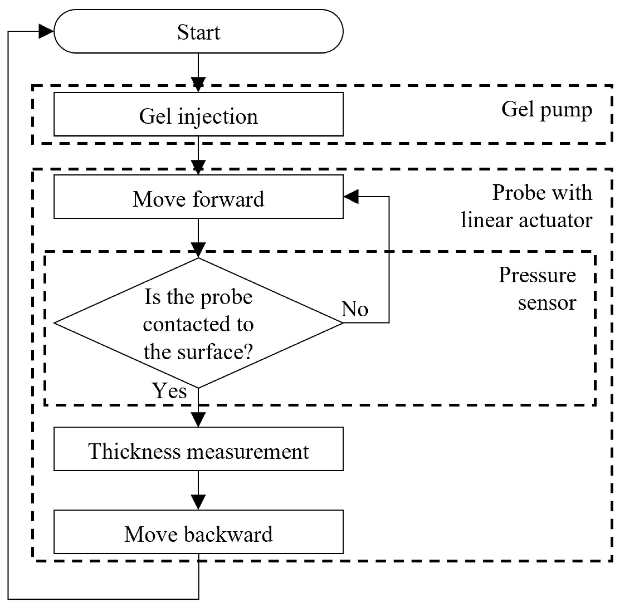
2.2. Design of the Probe with Linear Actuator

In this study, an ultrasonic probe with a linear actuator is introduced for measuring metal thickness. The probe emits a pulse wave and then receives the reflected pulse. Finally, the thickness is calculated by multiplying the velocity of sound in the object by half of the measured round-trip time. To automate the metal thickness measurement, the robot must generate this pressing motion of the probe. Additionally, coupling gel must be dispensed to facilitate the propagation of solid ultrasonic waves [23]. Moreover, due to the robot’s design for overcoming steps, the distance between the robot body, where the sensor is installed, and the target surface varies depending on the surface conditions as shown in Figure 2.
Therefore, we developed a device in which the linear actuator moves the probe, and coupling gels are injected by a DC motorized pump. Figure 3 shows a design of the probe with a linear actuator, and Figure 4 shows a sensor installed on a wall-climbing robot. The linear actuator moves the probe to the surface and returns it to the initial position. The gel pump injects the coupling gel from the gel tank. The gel pipe is connected to the servo arm, allowing the servo motor to move its end of the gel pipe to the probe for gel injection. Springs are used to compensate for the small gaps caused by the contact angle of the probe, ensuring consistent contact on vertical flat surfaces. For curved surfaces, a large storage tank has a large diameter, so the effect of the curved surface is small and limited. When measuring smaller tanks, the curvature becomes larger. To scale to tanks of different sizes or geometries, the probe of the device should be selected to fit the curved surfaces of the tank. Variations in the tank material influence the speed of sound that travels through the solid. The ultrasonic thickness gauge must account for these material differences and adjust for the velocity of sound waves in corresponding materials.

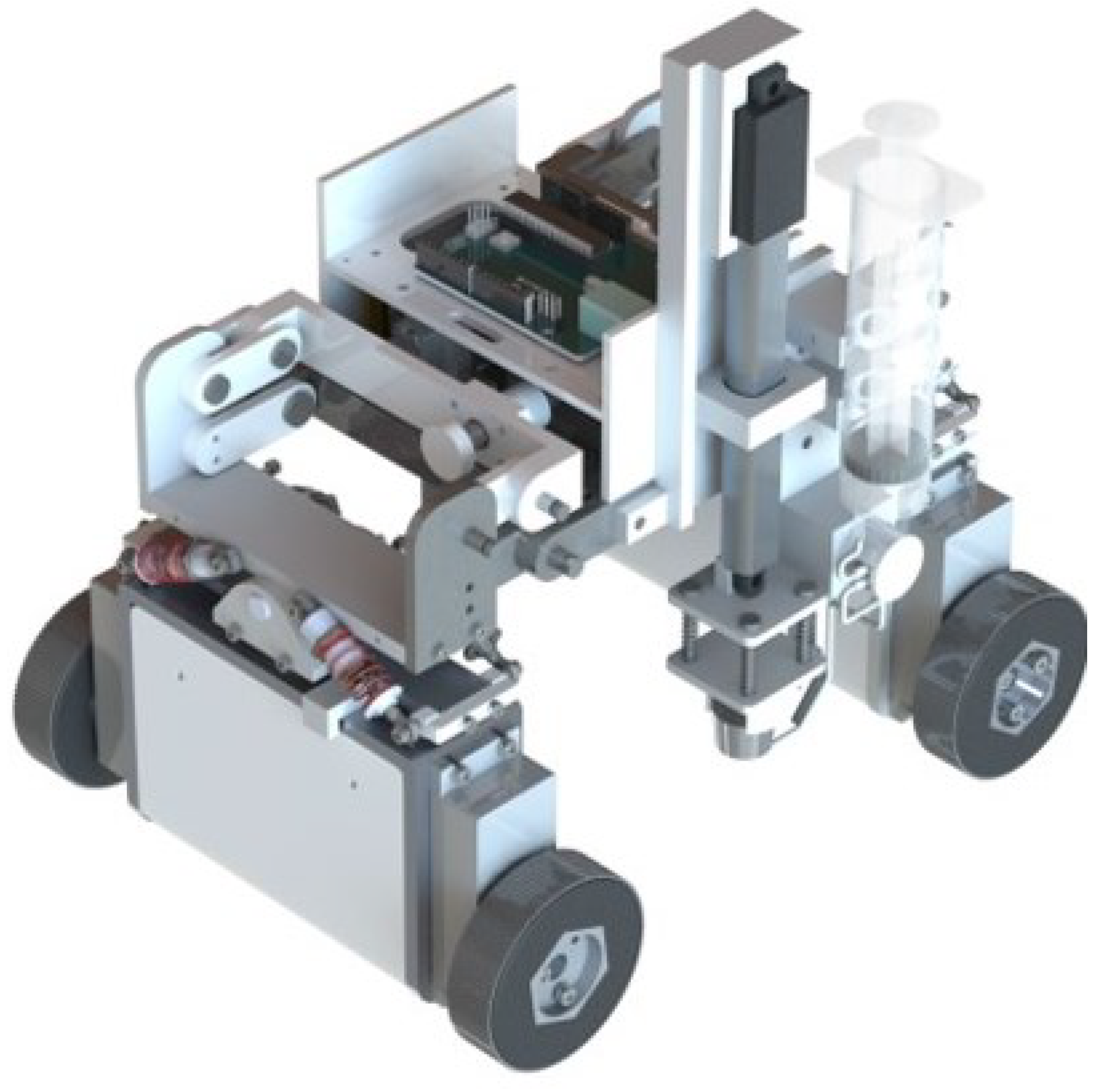
2.3. Development of the Prototype Device

Figure 5 shows a developed ultrasonic probe with a linear actuator. The linear actuator (LA-T8W-6-30-100/155-32 from Leioutejidian, Shenzhen, China) has a stroke range of 0 mm to 100 mm with a movement speed of 30 mm/s. We confirmed that the gel pump (LFP101ADB from Hangzhoulifu, Hangzhou, China) can dispense a sufficient amount of coupling gel for one measurement in 15 s. The maximum injection volume was 2 mL/min when using water. The rest of the parts were made by 3D printers. The linear actuator, gel pump, and servo motor (MG90S from Tower Pro, Singapore) were controlled by an Arduino UNO-compatible board.The probe was connected to the ultrasonic thickness sensor (SW-6510S from SNDWAY, Dongguan, China). The mass of the developed device was 0.3 kg, and the thickness sensor was 0.2 kg. The total mass was less than the robot specification payload. The range of distance to the surface from the robot body that should be covered is 102 mm to 122 mm (see Figure 2). The developed device can achieve a distance range of 85 mm to 185 mm. Thus, the probe can reach the surface regardless of the robot’s wheel angles. A control flow diagram showing the linear actuator, ultrasonic probe, and gel pump is shown in Figure 6.
To ensure stable contact and prevent overshooting or probe rebound, a pressure sensor (FSR400 from Interlink Electronics, Fremont, CA, USA) was attached between the probe and its holder to provide feedback and prevent measurement errors. The sensor has a force sensitivity range of 0.1 to 10 N. The pressure sensor detects when the probe makes contact with the surface. Figure 7 shows the pressure sensor reading of the device. The green area represents the phase for the injection of the coupling gel; the phase where the actuator moved forward to press the surface is shown as the blue area; the phase where the probe makes contact with the surfaces is shown by the red area; and the gray area represents the backward movement of the actuator to move to the initial position. When there is no contact, the value is low, but it increases when the probe makes contact with the surface. When the value exceeds a threshold, the device waits for a few moments to measure the thickness, and then the actuator returns to its initial position. The threshold and contact time were established through multiple attempts. Since our design utilizes only two outputs (the liner actuator and the pump) and a single input (the pressure sensor), the computational cost and mechanical complexity do not significantly impact robot control. The control frequency of the device was 20 Hz.

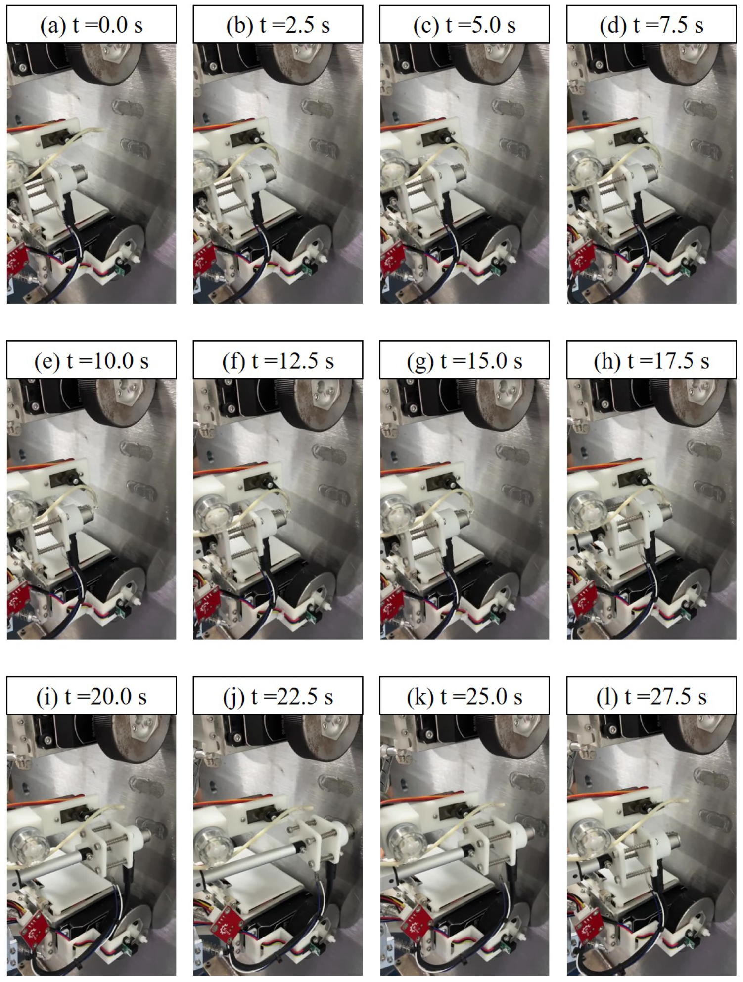
2.4. Fundamental Experiment

The metal thickness was measured at a single point using the ultrasonic probe with the linear actuator developed as a prototype device mounted on the climbing robot. Figure 8 shows the image frames captured during the inspection with a 2.5 s interval. Figure 8a shows the phase in which the servo motor moves the gel pipe to the injection point. Figure 8b–h show the phases where a motorized pump dispenses coupling gel onto the probe. Figure 8i shows the actuator moving forward, and Figure 8j shows the probe making contact with the surface. After completing the measurement, the actuator returned to its initial position as shown in Figure 8k,l. Each measurement sequence took approximately 30 s.

3. Results

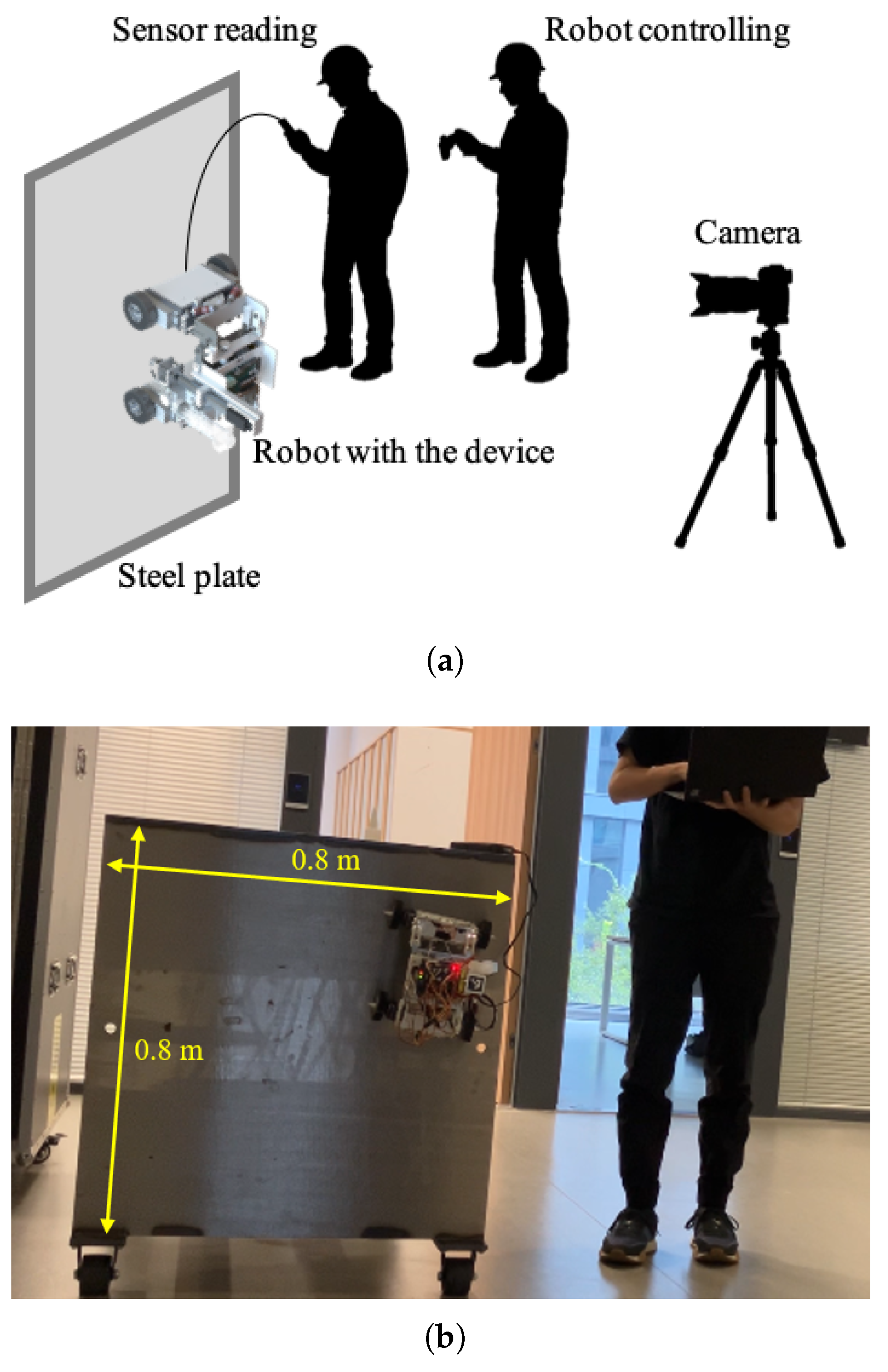
3.1. Experimental Setups

We conducted a thickness measurement experiment using a prototype device as shown in Figure 5, and a magnet-type climbing robot as shown in Figure 1. The metal thickness measurement experiment was conducted in the environment shown in Figure 9a. Before the experiment, an ArUco marker [32] was placed on the prototype device to track its position. The robot was manually controlled, and an on-ground camera recorded its movement on the steel box. The experiment was conducted on the steel box, which consists of four metal plates as shown in Figure 9b. In the experiment, we used the vertical flat surface of the steel box, which had no coating or rust. The length of each edge was 0.8 m. The thickness was 10 mm, as oil tanks typically have a thickness ranging from 5 mm to 10 mm [29].

3.2. Results

The measurement success rate was 65.9%, with 29 successful measurements and 15 errors out of a total of 44 points measured. In this experiment, to determine the overall success rate, we moved the robot to the next point instead of retrying a measurement, even when a measurement failure occurred. Figure 10 shows the result of the measurements. The position of the robot was tracked using the ArUco marker [32] on top of the device. The blue points represent successful measurements, while the red points represent failures. Among the successful measurements, the average measured thickness was 9.93 mm, whereas the actual metal thickness was 10 mm. We calculated the average measurement error compared to the reference thickness, which was 0.7% in this experiment. The results show an average error of 0.07 mm, which was within the allowable error range of 0.2 mm [27]. Figure 11 shows the box plot of the result. The largest error (+5.07 mm) was observed when the robot moved in a zigzag pattern along the wall and changed its orientation. The second largest error (−3.78 mm) was observed due to excessive coupling gel injection, causing the ultrasonic gauge to output a value before the probe was properly grounded.

4. Discussion

In a related study [26], the average measurement error compared to the reference values was 2% for a robot that used six legs to move the inspection probe to the surface. In the experiment of this study, the measurement error compared to the reference thickness was 0.7%. Therefore, the results showed that the developed sensor device could be used for the development of a climbing robot-based system for inspecting steel structures at a certain level. However, the measurement success rate was 65.9% and requires improvement. The system’s performance is sensitive to initial alignment and gel distribution inconsistencies; therefore, real-time adaptive feedback is required to increase the measurement success rate. In this experiment, the robot did not remeasure the same point when it failed to obtain a value; however, in actual operations, the success rate can be increased by remeasuring when an attempt fails. We believe that both gel injection and actuator control are important for overall performance, as the gel injection pump fills the gap between the probe and the surface, and the actuator ensures proper contact. Moreover, design improvements can improve the success rate of measurement. The probe holder with a spring should be redesigned to apply a more consistent force, duration, and angle against the surface when pressing the probe. The kinematics model of the end effector’s position ensures alignment with the desired trajectory in [33], which offers useful parallels to automation strategies in metal thickness inspection.
The climbing robot has a battery life of 50 min (see Table 2), and the device takes about 30 s to perform a single measurement, allowing for up to 100 measurements on a single charge. As the gel injection by the pump takes a long period during the measurement sequence, the pump capacity should be increased to allow for more measurements per unit of time.

Limitation

First, the testing setup is relatively limited, as the measurements were conducted only on a flat steel surface. The experiment results do not fully reflect the variability of curved and corroded surfaces encountered in real tank inspections. Further testing on cylindrical structures, plates with varying thicknesses, or surfaces with different roughness conditions would improve the system’s applicability.
One limitation is that the detected marker points do not precisely match the probe’s contact points. Therefore, the inspection points recorded by the robot contain some errors depending on the camera position. Calibrating the contact point, ArUco marker, and camera could resolve this issue. In this experiment, the objective was to validate the prototype device, so we used an ArUco marker for ease of implementation. However, these markers introduce a dependency on external visual tracking, which is not feasible in industrial, low-light settings or under adverse weather conditions. Therefore, localization and mapping methods have been studied in previous studies. A commonly proposed method involves installing sensors, such as lasers and cameras, on the ground to track the robot on the wall [10,16]. Moreover, self-localization by internal sensors was proposed. A method using an RGB-D camera to make a 3D map of target structures has been proposed [34,35]. Further study on path planning and localization is necessary to meet the low-energy-consumption requirements of climbing robots in bridge inspections [36].
Although this paper does not address external operational uncertainties, such as surface roughness, rust, or uneven tank geometry, implementing the self-localization and control methods described above could mitigate factors that reduce measurement accuracy and reliability.

5. Conclusions

The inspection of oil storage tanks is a critical measure to prevent the risk of oil leakage. The final goal of this study was to develop a fully automated tank inspection robotic system to reduce inspection costs. Previous studies on wall-climbing inspection robots have primarily focused on stable locomotion on wall surfaces, with only a few addressing the integration of actual inspection sensors. This is because ultrasonic metal thickness measurement requires the robot to dispense coupling gel properly and firmly press the probe against a measurement surface [23]. Therefore, we propose a method for measuring metal thickness using an ultrasonic probe with a linear actuator for a magnet-type climbing robot. Our prototype successfully demonstrated its functionality in the practical applications for an oil storage tank inspection system through experimentation. The prototype achieved a measurement success rate of 65.9% and an average error of 0.7% compared to a reference thickness.
Finally, the implementation of autonomous control remains a subject for future work. In an inspection operation, the recording of the autonomous robot’s movement and inspection results is essential. The entire measurement system should be evaluated through analysis that examines how its performance metrics—such as measurement repeatability, probe alignment accuracy, and surface contact reliability—vary with changes in actuator displacement, gel volume, or surface irregularities, and how these factors impact the accuracy of thickness readings to assess real-world robustness.

Author Contributions

Conceptualization, Y.N. and C.W.; methodology, Y.N.; software, Y.N.; validation, Y.N. and C.W.; formal analysis, Y.N.; investigation, Y.N.; resources, W.S.; data curation, Y.N. and C.W.; writing—original draft preparation, Y.N.; writing—review and editing, Y.N.; visualization, Y.N.; supervision, W.S.; project administration, W.S.; funding acquisition, W.S. All authors have read and agreed to the published version of the manuscript.

Funding

This research was funded by the Eaglet Planning Cultivation Project of Zhejiang Administration for Market Regulation (Grant No. CY2022231).

Institutional Review Board Statement

Not applicable.

Informed Consent Statement

Not applicable.

Data Availability Statement

Data are contained within the article.

Conflicts of Interest

The authors declare no conflicts of interest.

References

  1. Yaguchi, H.; Kimura, I.; Sakuma, S. A New Type of Rotary Magnetic Actuator System Using Electromagnetic Vibration and Wheel. Actuators 2020, 9, 51. [Google Scholar] [CrossRef]
  2. Chen, F.; Wang, L.; Wang, Y.; Zhang, H.; Wang, N.; Ma, P.; Yu, B. Retrieval of dominant methane (CH4) emission sources, the first high-resolution (1–2 m) dataset of storage tanks of China in 2000–2021. Earth Syst. Sci. Data 2024, 16, 3369–3382. [Google Scholar] [CrossRef]
  3. Ma, S.; Tang, X.; Ma, W.; Liu, J.; Xiao, L. An Unmanned Cleaning Robot for the Inner Wall of Large LNG Tanks. In Proceedings of the 2022 International Conference on Advanced Robotics and Mechatronics (ICARM), Guilin, China, 9–11 July 2022; pp. 562–568. [Google Scholar] [CrossRef]
  4. Kalra, L.; Shen, W.; Gu, J. A Wall Climbing Robotic System for Non Destructive Inspection of Above Ground Tanks. In Proceedings of the 2006 Canadian Conference on Electrical and Computer Engineering, Ottawa, ON, Canada, 7–10 May 2006; pp. 402–405. [Google Scholar] [CrossRef]
  5. Mazumdar, A.; Asada, H.H. Mag-Foot: A steel bridge inspection robot. In Proceedings of the 2009 IEEE/RSJ International Conference on Intelligent Robots and Systems, St. Louis, MO, USA, 10–15 October 2009. [Google Scholar] [CrossRef]
  6. Akahori, S.; Higashi, Y.; Masuda, A. Development of an Aerial Inspection Robot with EPM and camera arm for steel structures. In Proceedings of the 2016 IEEE Region 10 Conference (TENCON), Singapore, 22–25 November 2016; pp. 3542–3545. [Google Scholar] [CrossRef]
  7. Kalra, L.P.; Gu, J.; Meng, M. A Wall Climbing Robot for Oil Tank Inspection. In Proceedings of the 2006 IEEE International Conference on Robotics and Biomimetics, Kunming, China, 17–20 December 2006; pp. 1523–1528. [Google Scholar] [CrossRef]
  8. Chen, J.; Cao, X.; Xu, H.; Zhang, X.; Deng, Z. Structure Design and Characteristic Analysis of Compound-Driven Unit for Pipeline Robot. In Proceedings of the 2020 5th International Conference on Advanced Robotics and Mechatronics (ICARM), Shenzhen, China, 18–21 December 2020; pp. 353–358. [Google Scholar] [CrossRef]
  9. Yang, W.; Yang, C.; Zhang, R.; Zhang, W. A Novel Worm-inspired Wall Climbing Robot with Sucker-microspine Composite Structure. In Proceedings of the 2018 3rd International Conference on Advanced Robotics and Mechatronics (ICARM), Singapore, 18–20 July 2018; pp. 744–749. [Google Scholar] [CrossRef]
  10. Zhang, X.; Zhang, Y. Adaptive Robust Tracking Control of Wall-climbing Robot Based on Constraint Following Theory. In Proceedings of the 2022 International Conference on Advanced Robotics and Mechatronics (ICARM), Guilin, China, 9–11 July 2022; pp. 696–701. [Google Scholar] [CrossRef]
  11. Amakawa, T.; Yamaguchi, T.; Yamada, Y.; Nakamura, T. Proposing an adhesion unit for a traveling-wave-type, omnidirectional wall-climbing robot in airplane body inspection applications. In Proceedings of the 2017 IEEE International Conference on Mechatronics (ICM), Churchill, VIC, Australia, 13–15 February 2017; pp. 178–183. [Google Scholar] [CrossRef]
  12. Wang, C.; Gu, J.; Li, Z. Switching Motion Control of the Climbing Robot for Aircraft Skin Inspection. In Proceedings of the 2019 IEEE International Conference on Fuzzy Systems (FUZZ-IEEE), New Orleans, LA, USA, 23–26 June 2019; pp. 1–6. [Google Scholar] [CrossRef]
  13. Andrikopoulos, G.; Papadimitriou, A.; Brusell, A.; Nikolakopoulos, G. On Model-based Adhesion Control of a Vortex Climbing Robot. In Proceedings of the 2019 IEEE/RSJ International Conference on Intelligent Robots and Systems (IROS), Macau, China, 3–8 November 2019; pp. 1460–1465. [Google Scholar] [CrossRef]
  14. Alkalla, M.G.; Fanni, M.A.; Mohamed, A.M.; Hashimoto, S. Tele-operated propeller-type climbing robot for inspection of petrochemical vessels. Ind. Robot. Int. J. 2017, 44, 166–177. [Google Scholar] [CrossRef]
  15. Song, W.; Wang, Z.; Wang, T.; Ji, D.; Zhu, S. A Path Tracking Method of a Wall-Climbing Robot towards Autonomous Inspection of Steel Box Girder. Machines 2022, 10, 256. [Google Scholar] [CrossRef]
  16. Li, J.; Li, B.; Dong, L.; Wang, X.; Tian, M. Weld Seam Identification and Tracking of Inspection Robot Based on Deep Learning Network. Drones 2022, 6, 216. [Google Scholar] [CrossRef]
  17. Li, J.; Feng, H.; Tu, C.l.; JIN, S.s.; WANG, X.s. Design of Inspection Robot for Spherical Tank Based on Mecanum Wheel. In Proceedings of the 2019 Far East NDT New Technology & Application Forum (FENDT), Qingdao, China, 24–27 June 2019; pp. 218–224. [Google Scholar] [CrossRef]
  18. Duan, Z.; Fang, G.; Shi, G.; Qian, H.; Cui, J.; Zhang, J. The Design and Performance Investigation of a Split Four-Track Water-Jet Cleaning Robot for Steel Gate Panels. Actuators 2024, 13, 528. [Google Scholar] [CrossRef]
  19. Zhang, Y.; Dodd, T.; Atallah, K.; Lyne, I. Design and optimization of magnetic wheel for wall and ceiling climbing robot. In Proceedings of the 2010 IEEE International Conference on Mechatronics and Automation, Xi’an, China, 4–7 August 2010; pp. 1393–1398. [Google Scholar] [CrossRef]
  20. Ji, H.; Li, P.; Wang, Z. Analysis and Simulation of Permanent Magnet Adsorption Performance of Wall-Climbing Robot. Actuators 2024, 13, 337. [Google Scholar] [CrossRef]
  21. Zhao, Y.; Zhang, J.; Zhang, Y.; Lin, Y. Research on Foundation Settlement Detection Method of Large Crude Oil Storage Tank. In Proceedings of the 2021 IEEE Far East NDT New Technology & Application Forum (FENDT), Kunming, China, 14–17 December 2021; pp. 134–139. [Google Scholar] [CrossRef]
  22. Zhang, D.; Watson, R.; Dobie, G.; MacLeod, C.; Pierce, G. Autonomous Ultrasonic Inspection Using Unmanned Aerial Vehicle. In Proceedings of the 2018 IEEE International Ultrasonics Symposium (IUS), Kobe, Japan, 22–25 October 2018; pp. 1–4. [Google Scholar] [CrossRef]
  23. Otsuki, Y.; Nguyen, S.T.; La, H.M.; Wang, Y. Autonomous Ultrasonic Thickness Measurement of Steel Bridge Members Using a Climbing Bicycle Robot. J. Eng. Mech. 2023, 149, 8. [Google Scholar] [CrossRef]
  24. Ding, Y.; Sun, Z.; Chen, Q. Non-contacted Permanent Magnetic Absorbed Wall-climbing Robot for Ultrasonic Weld Inspection of Spherical Tank. MATEC Web Conf. 2019, 269, 02013. [Google Scholar] [CrossRef]
  25. Enjikalayil Abdulkader, R.; Veerajagadheswar, P.; Htet Lin, N.; Kumaran, S.; Vishaal, S.R.; Mohan, R.E. Sparrow: A Magnetic Climbing Robot for Autonomous Thickness Measurement in Ship Hull Maintenance. J. Mar. Sci. Eng. 2020, 8, 469. [Google Scholar] [CrossRef]
  26. Phlernjai, M.; Ratsamee, P. Multi-Legged Inspection Robot with Twist-Based Crouching and Fine Adjustment Mechanism. J. Robot. Mechatron. 2022, 34, 588–598. [Google Scholar] [CrossRef]
  27. Zhang, M.; Zhang, X.; Li, M.; Cao, J.; Huang, Z. Optimization Design and Flexible Detection Method of a Surface Adaptation Wall-Climbing Robot with Multisensor Integration for Petrochemical Tanks. Sensors 2020, 20, 6651. [Google Scholar] [CrossRef] [PubMed]
  28. Nishimura, Y.; Zheng, T.; Song, W. Metal Thickness Measurement Module with Scotch Yoke Mechanism for Tank Inspections. In Proceedings of the 2024 IEEE International Conference on Advanced Intelligent Mechatronics (AIM), Boston, MA, USA, 15–19 July 2024; pp. 734–739. [Google Scholar] [CrossRef]
  29. Shen, W.; Gu, J.; Shen, Y. Proposed wall climbing robot with permanent magnetic tracks for inspecting oil tanks. In Proceedings of the IEEE International Conference Mechatronics and Automation, Niagara Falls, ON, Canada, 29 July–1 August 2005; pp. 2072–2077. [Google Scholar] [CrossRef]
  30. Wang, C.; Zhu, S.; Song, W.; Zheng, T.; Ding, H.; Wang, B. Modeling of attractive force of magnetic wheel under different wall structure and attitude used for climbing robot. J. Mech. Sci. Technol. 2024, 38, 411–421. [Google Scholar] [CrossRef]
  31. Wang, C.; Zhu, S.; Song, W. Design and experiment of climbing robot for steel I-beam girder inspection. Ind. Robot. Int. J. Robot. Res. Appl. 2025, ahead-of-print. [Google Scholar] [CrossRef]
  32. Garrido-Jurado, S.; Muñoz-Salinas, R.; Madrid-Cuevas, F.; Marín-Jiménez, M. Automatic generation and detection of highly reliable fiducial markers under occlusion. Pattern Recognit. 2014, 47, 2280–2292. [Google Scholar] [CrossRef]
  33. Ben Hazem, Z.; Guler, N.; Altaif, A.H. A study of advanced mathematical modeling and adaptive control strategies for trajectory tracking in the Mitsubishi RV-2AJ 5-DOF Robotic Arm. Discov. Robot. 2025, 1, 2. [Google Scholar] [CrossRef]
  34. Hong, K.; Wang, H.; Yuan, B. Inspection-Nerf: Rendering Multi-Type Local Images for Dam Surface Inspection Task Using Climbing Robot and Neural Radiance Field. Buildings 2023, 13, 213. [Google Scholar] [CrossRef]
  35. Yang, L.; Li, B.; Feng, J.; Yang, G.; Chang, Y.; Jiang, B.; Xiao, J. Automated wall-climbing robot for concrete construction inspection. J. Field Robot. 2022, 40, 110–129. [Google Scholar] [CrossRef]
  36. Xu, W.; Hou, C.; Li, G.; Cui, C. Path Planning for Wall-Climbing Robots Using an Improved Sparrow Search Algorithm. Actuators 2024, 13, 370. [Google Scholar] [CrossRef]
Figure 1. Magnet-type climbing robot.
Actuators 14 00299 g001
Figure 2. Distance to the surface from the robot body.
Actuators 14 00299 g002
Figure 3. Design of the device with the linear actuator.
Actuators 14 00299 g003
Figure 4. Magnet-type robot with the developed device.
Actuators 14 00299 g004
Figure 5. Developed device with the linear actuator.
Actuators 14 00299 g005
Figure 6. Control flow diagram of the linear actuator, ultrasonic probe, and gel pump.
Actuators 14 00299 g006
Figure 7. Pressure sensor reading. Green area: gel injection; blue area: actuator forward movement; red area: probe pressing against the surface; gray area: actuator backward movement.
Actuators 14 00299 g007
Figure 8. Inspection sequence (2.5 s interval) showing actuator movement, gel injection timing, and ultrasonic signal acquisition over time.
Actuators 14 00299 g008
Figure 9. Experiment setting. (a) Experiment design; (b) climbing robot on a steel box surface.
Actuators 14 00299 g009
Figure 10. Experiment results [mm]. Blue points: successful measurements; red points: failed measurements; ①: largest error caused by the change in the robot orientation; ②: second-largest error caused due to excessive coupling gel injection.
Actuators 14 00299 g010
Figure 11. Box plot of the measured thicknesses.
Actuators 14 00299 g011
Table 1. Comparison table summarizing related works.
ReferenceYearMethodGel Injection
Ding et al. [24]2019Electric pusherN/A
Enjikalayil et al. [25]2020SolenoidN/A
Zhang et al. [27]2020Four-bar linkage mechanismAir compressor and diaphragm pump (on-ground)
Phlernjai et al. [26]2022Crouching motion of the legged robotN/A
Otsuki et al. [23]2023Four-bar linkage mechanismPeristaltic pump (onboard)
Nishimura et al. [28]2024Scotch Yoke mechanismN/A
Proposed2025Linear actuatorPeristaltic pump (onboard)
N/A: Not applicable or not reported.
Table 2. Robot specification.
Mass [kg]3.8
Size [mm × mm × mm]280 × 197 × 160
Payload [kg]1.2
Climbing mechanismMagnetic wheel
Actuator torque (wheel) [Nm]10
Battery life [min]50
Applicable obstacle height [mm]20
Corner (concave/convex)🗸/🗸
🗸: Applicable.
Disclaimer/Publisher’s Note: The statements, opinions and data contained in all publications are solely those of the individual author(s) and contributor(s) and not of MDPI and/or the editor(s). MDPI and/or the editor(s) disclaim responsibility for any injury to people or property resulting from any ideas, methods, instructions or products referred to in the content.

