1. Introduction
The introduction of electro-hydrostatic actuators onboard aircraft represented a major change in the structure of aircraft control systems. All the power distributed through the hydraulic system for operating the flight controls was transferred to the electrical power system. The main motivation for this change was to increase the reliability of the flight control system. The transfer of energy through the hydraulic system is totally dependent on the hydraulic fluid reserve. The loss of hydraulic fluid means the inoperability of all flight controls. Although there are three independent hydraulic systems onboard airliners, in the 1980s, there were two aviation accidents that involved the inoperability of flight controls precisely due to the loss of hydraulic fluid. The disasters of JAL flights 123 [
1] and United Airlines 232 [
2] became viral and sparked research initiatives aimed at eliminating this problem of flight controls.
The distribution of electrical energy from the source to the actuators is much more efficient and reliable than that of hydraulic energy. As a result, the transition from the concept of classical hydraulic actuators of flight controls to the power-by-wire (PBW) concept, where energy is transmitted from the source to the actuator in electrical form, has begun onboard aircraft. The transition is currently in full swing. Newly designed aircraft are using this technology. The technology is also expanding to more and more aircraft categories.
This transition to PBW aircraft has raised many problems, some already solved, while others are under research. An interesting and comprehensive synthesis on the issue of electro-hydrostatic actuators (EHA) can be found in [
3].
Unlike classic electro-hydraulic servoactuators (EHS), which use a hydraulic cylinder to convert hydraulic energy received from pumps into mechanical energy and a servovalve to control it [
4], EHA uses a local hydraulic circuit that converts electrical energy received from generators into mechanical energy to actuate flight controls [
5]. The problems arising in PBW systems are multiple [
6]. The entire power conveyed through the hydraulic system is now transferred to the electrical system of the aircraft. This means that the electrical system of transport aircraft can convey powers of MW order. It would be preferable to completely replace the hydraulic circuit with a mechanical device, thus using electro-mechanical servoactuators [
7]. Experimental tests, however, have shown that mechanical gearboxes cannot withstand the demands of flight control, leading to their seizure. In addition, the backlash occurring over time due to the wear of mechanical gears means that the hydraulic circuits used in the construction of the EHA cannot yet be abandoned.
A major problem on aircraft board is the weight of the servoactuators. The much simpler structure of the EHS makes them even lighter than an EHA. An EHS is generally composed of a hydraulic cylinder controlled by a servo valve. An EHA generally contains, in addition to the hydraulic cylinder, an electric motor, a pump, a hydraulic accumulator and a valve system. Depending on the chosen design, it may also contain other elements. However, the overall flight control system remains questionable, given that the EHS also requires the entire aircraft hydraulic system to function.
The automation of EHA implies many research directions. Problems like neural networks diagnosis of the EHA or EHA disturbance rejection are studied in [
8,
9].The control of EHA-based flight controls is more complicated than that of EHS-based flight controls. In this regard, there are many studies in the literature using different control techniques, from simple ones based on PID controllers to complex techniques of robust control, neural control, backstepping control, etc. [
10,
11,
12,
13,
14,
15,
16,
17].
The study presented here targets four types of EHA, one of fixed pump type with variable motor (FPVM) and three variable pump variants with fixed motor (VPFM). The main issue addressed is that of the advantages and disadvantages offered by the FPVM and VPFM configurations from different points of view. EHA configurations are presented in detail in [
18]. The FPVM variant is simpler in construction but involves the permanent variation of the pump drive motor speed, depending on the command received. The pump motor is a high-power one, which implies a heavy load on its control converter. The VPFM variant keeps the main pump motor speed constant and varies the pump displacement to control the servoactuator. In this case, the main motor converter is less stressed, but a pump displacement control system is required.
Variation of the pump displacement in the VPFM version is provided in some different ways. Typically, an axial piston pump with tilt swash plate is used. The movement of the pump tilt plate can be achieved either using a controlled electric motor that drives the swash plate or using an additional hydraulic circuit that controls the swash plate. If an electric motor is used, it is necessary to transmit the movement to the swash plate through mechanical transmission. For this purpose, if the electric motor is of high speed/low torque, a high ratio mechanical transmission is necessary. A mechanical transmission with high ratio is the worm–worm wheel mechanism. This version is denoted in the following as VPFM-HR. If the electric motor is of low speed/high torque, a low ratio mechanical transmission is necessary. A mechanical transmission with a low ratio can be a gear set. This version will be denoted in the following as VPFM-LR.
If an additional hydraulic circuit is used for driving the swash plate, an additional pump is necessary, generally mounted on the same shaft as the main pump, a servo-valve, and an additional hydraulic cylinder. In the sequel, we denote this version as FPVM-HYD.
Each of the four versions has its own issues. Different functioning problems appear in each case and in this paper, we identify these problems and highlight the advantages and disadvantages that appear in their functioning.
In the paper, simulation models are developed for the studied variants and the variation of the parameters in each system is monitored to ascertain the advantages and disadvantages. Furthermore, considerations are presented over other advantages and disadvantages than those resulting directly from the numerical simulations but related to the servoactuator configuration and its operation. In
Section 2, the FPVM-type EHA is presented. In
Section 3, the VPFM-type EHA with a low gear ratio for the pump displacement command is presented. In
Section 4, the VPFM-type EHA with a high gear ratio of the pump displacement command is presented. In
Section 5, the VPFM-type EHA with hydraulic control of the pump displacement is presented.
Section 6 presents a comparative synthesis between the studied configurations. Finally,
Section 7 gives the conclusions of the work. The simulation schemes are performed using the AMESIM SIMCENTER ACADEMIC BUNDLE software version 2304. To facilitate comparison, the same test signal is used for all studied configurations.
The operating principles of common types of EHA servoactuators are presented in detail in [
19,
20,
21,
22]; hence, we do not insist on the operating principles of each configuration. For each configuration, we present only the basics.
We start from an actuator for an aileron of a transport aircraft, for which the parameters in
Table 1 were imposed.
To achieve these parameters, the parameters of the servoactuator components presented in
Table 2 were calculated.
Excepting the gear pump, these are the parameters of the common components used in all the EHA configurations studied. For each configuration, other components may appear, presented for each case separately.
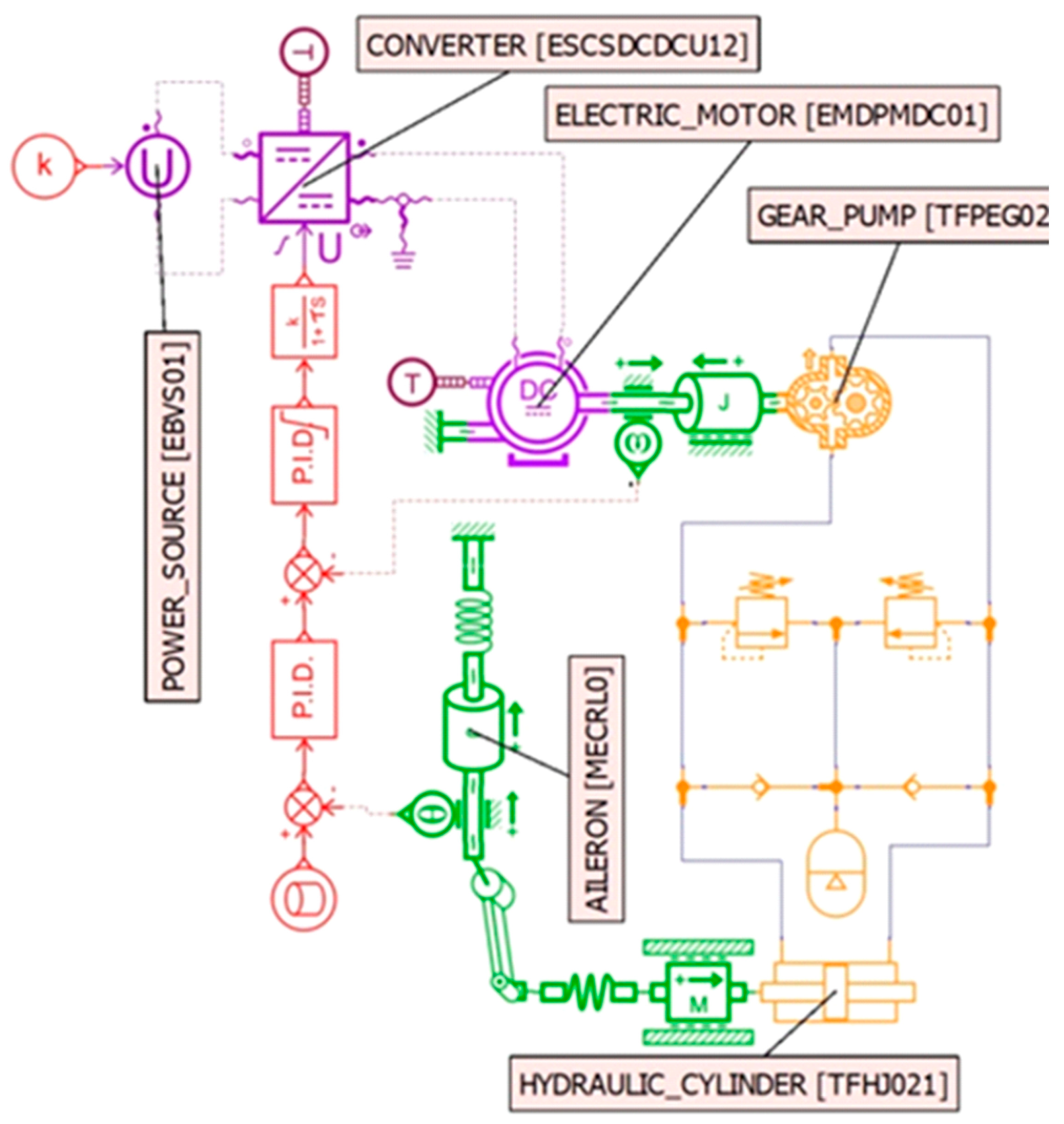
2. FPVM Type EHA
The FPVM type servoactuator is shown in
Figure 1.
In the case of the FPVM servoactuator, the hydraulic cylinder is filled by a fixed displacement pump, usually with gears, driven by the electric motor. To actuate the aileron, the electric motor varies its rotation speed and rotation direction to transport the hydraulic fluid between the cylinder chambers. On the other hand, the electric motor is powered by a controlled converter, to obtain the required rotation speed for the pump. The control loop contains a PID controller for the pump rotation speed and another external loop that varies the rotation speed depending on the error between the control signal and the aileron position. The power supply, a real ±270 VDC differential, in the simulation scheme, is modeled by a single 540 VDC source. No other components are required for the FPVM type servoactuator.
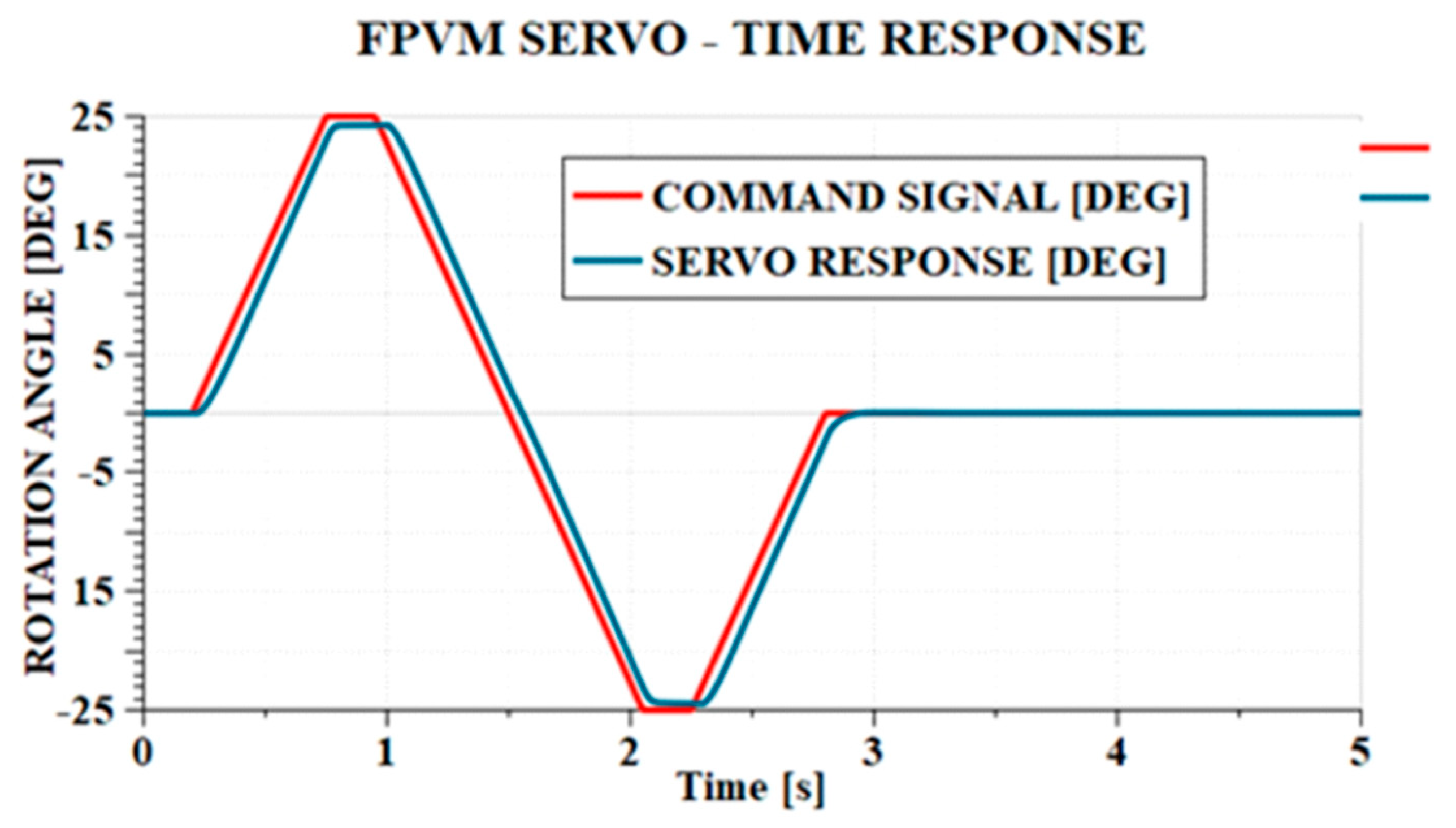
The control signal used is composed of three ramp portions with maximum steering speed, the first between 0° and 25°, the second between 25° and −25°, and the third between −25° and 0°. There is a short constant signal between the first and second ramps, as well as between the second and third ramps. The sequence begins and ends with a constant signal of 0°. The same test signal is applied to all the configurations and the necessary conclusions are drawn.
The time response of the FPVM servoactuator is shown in
Figure 2.
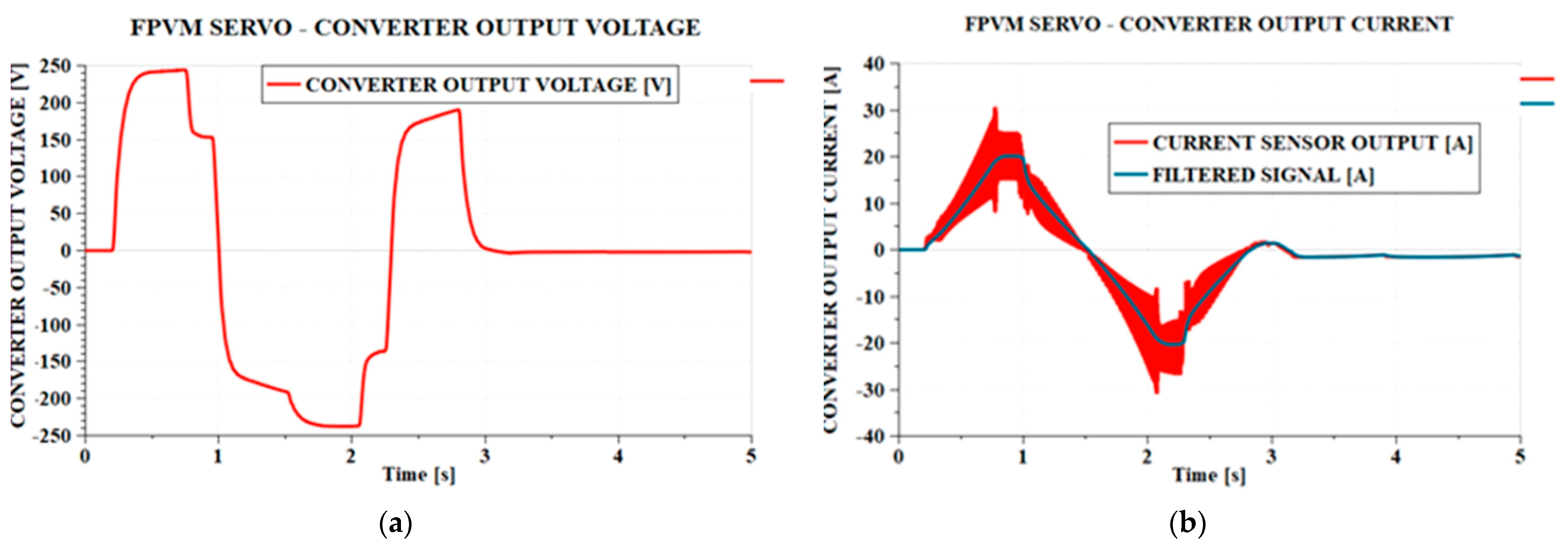
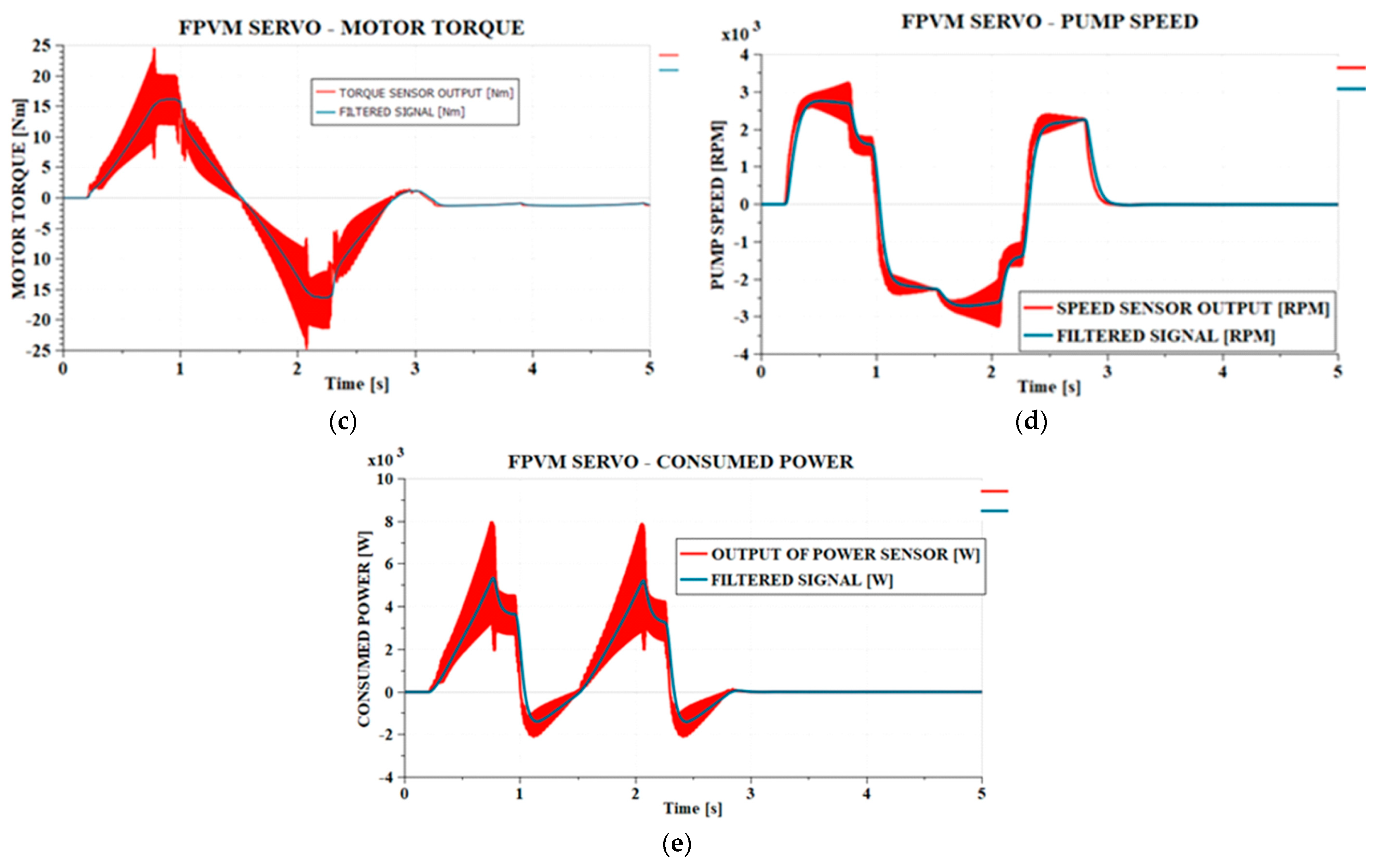
Figure 3 shows the driving motor parameters—voltage, current, shaft torque, angular velocity, and power consumption.
Regarding the servoactuator response time, it is not very good. The maximum positioning error is 2.5° and the maximum delay is 0.055 s, at the maximum aileron steering speed. Although the maximum time delay is very close to the parameters required for aircraft command surfaces (maximum 0.05 s), the maximum positioning error of 2.5° far exceeds the maximum imposed value of 1°.
Note that the command voltage has a smooth variation, but rest of the parameters—current, torque, rotation speed and power—show increasingly large oscillations as the aileron approaches the maximum stroke value, both in the positive and negative directions. These oscillations are generated by the flow pulsations of the gear pump, which further induce pressure pulsations in the hydraulic cylinder and torque oscillations at the pump shaft. These large amplitude current oscillations will additionally load the electrical power converter. In
Figure 3b–e, the values of the filtered parameters with an aperiodic block of order 1 with a time constant of 0.01 s have also been represented, so that an image of the average values of those parameters can be obtained, for the purpose of subsequent dimensioning of the electronic system. It is noticed that the current oscillations reach peaks of up to 30 A under conditions in which the maximum filtered value is approximately 20 A. Also, the power absorbed by the electric motor reaches peaks of maximum 8 kW, given that the maximum filtered value is approximately 5.2 kW. Therefore, we can state that this EHA configuration places a heavy load on the converter; on one hand, this is due to the frequent changes in speed and rotation direction of the motor, but it is also due to the oscillations induced by the flow pulsations of the pump. The pump’s flow pulsations increase in frequency as the number of the pump gear teeth increases but decrease in amplitude depending on the same parameter.
The power required to maintain the aileron steered at maximum stroke is approximately 3.5 kW, with amplitude pulsations of approximately 1 kW, and in stationary regime at zero aileron steering, the servoactuator consumes approximately 5 W of power.
Taking as a reference the common elements of the studied servoactuators, namely, the hydraulic cylinder, hydro-accumulator, valves, and the main motor, which, in this scheme, is the only motor, we note that in addition to these, only the gear pump appears. For the pump used in this scheme, the mass in the catalog is 1.14 kg [
23].
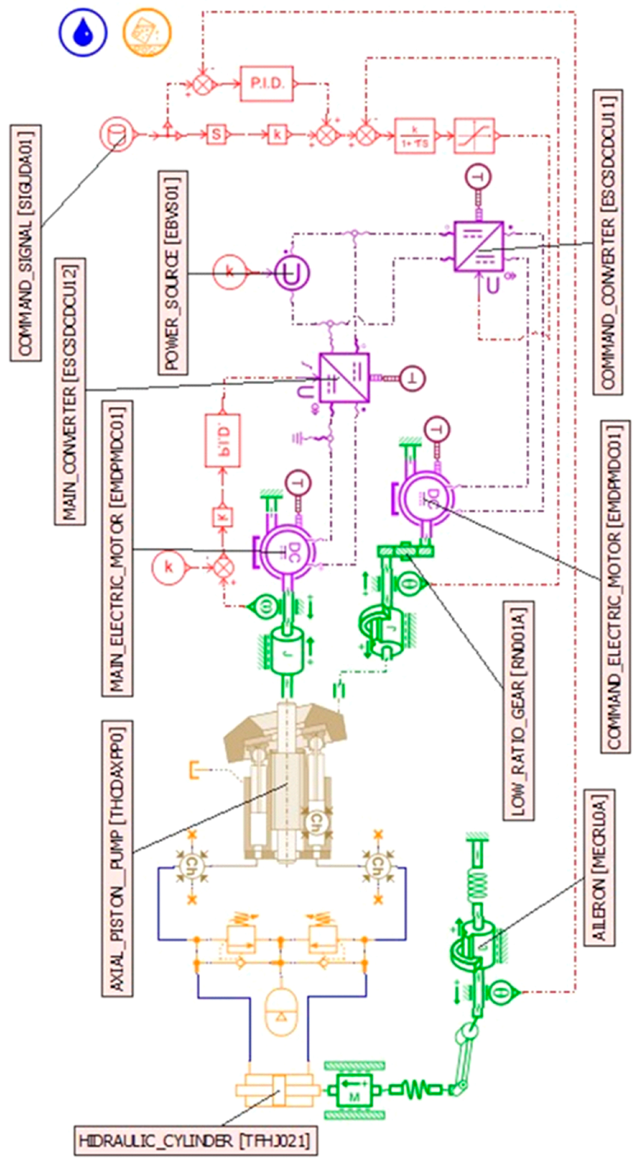
3. VPFM Type EHA with Small Transmission Ratio to Command Pump Displacement—(VPFM–LR)
The schematic of this type of servoactuator is shown in
Figure 4.
VPFM-type servoactuators maintain constant rotation speed of the pump motor and command the flow to the hydraulic cylinder by changing the pump displacement. The variable displacement pump used is typically of the swashing plate axial pistons pump type. To control such servoactuators, it is now necessary to command the pump’s swashing plate. This actuation can be done in several ways. Here, we present three possibilities.
A first way of driving the swashing plate uses an electric motor, through a device with a small transmission ratio. In this case, a gear set was considered. The electric motor controlling the plate, through the reducer, rotates the pump plate. Due to the small gear ratio, a high-torque but low-speed electric drive motor is required. The characteristics of the variable displacement pump considered in this paper are presented in
Table 3.
The same actuation is used, as in the previous case, the electric motor driving the pump is the same, and the supply voltage is the same. The pump motor is powered by an electric motor, which is now maintained at a constant rotation speed of 3000 rpm by means of a PID control loop. A second electric motor now appears, driving the pump plate, via the reducer. The gear ratio in this case is considered equal to 3.
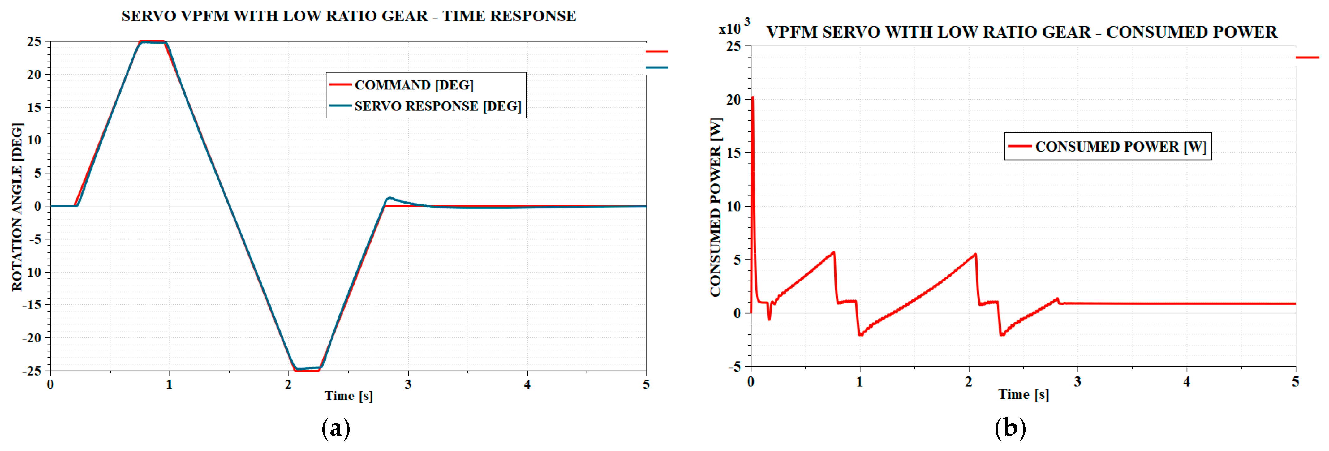
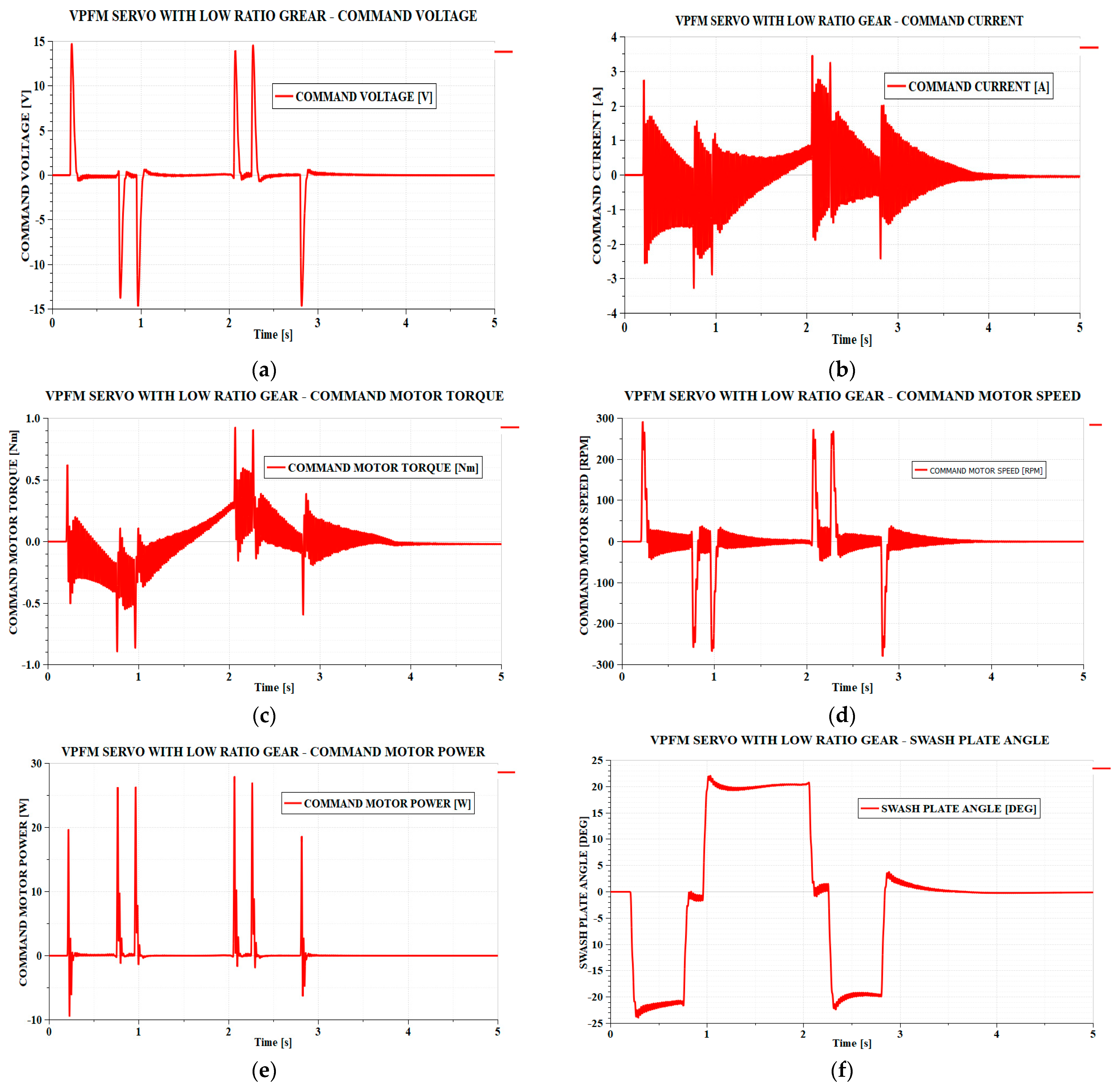
The behavior of the servoactuator under the same conditions as those in the previous section is shown in
Figure 5,
Figure 6 and
Figure 7.
From the point of view of the time response, the resulting behavior is good. The time delay is below 0.05 s and the maximum error over the entire interval is approximately 0.5°. Only at the end of the last ramp variation does an error of 1.2° appear, which remains above the maximum error allowed for an interval of 0.1 s.
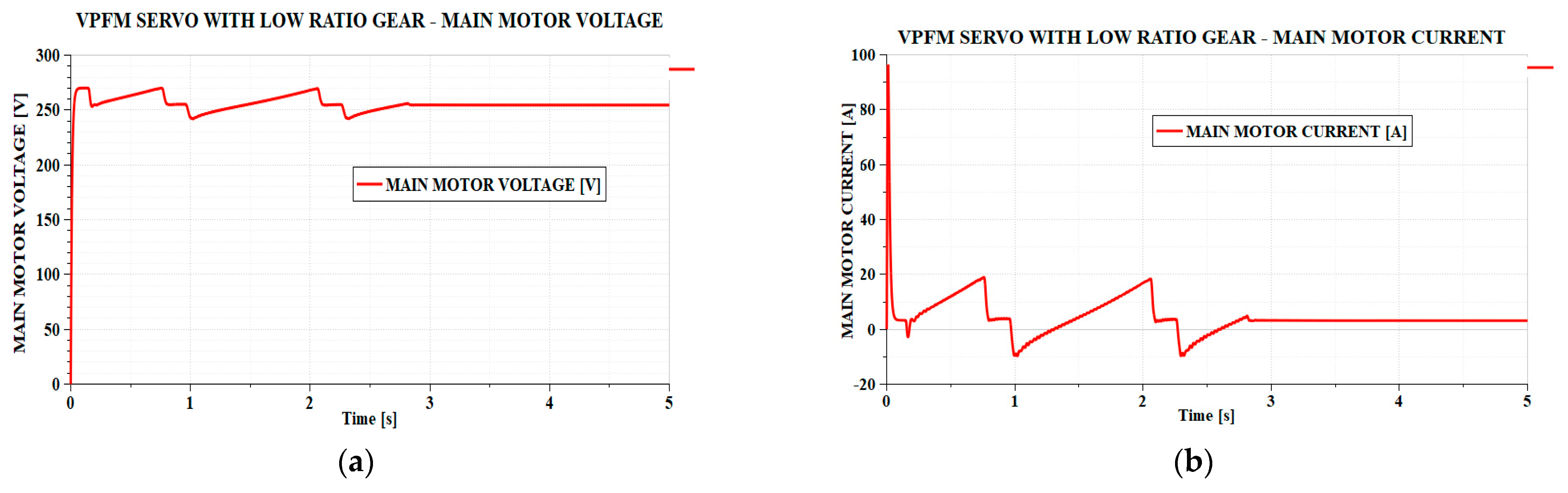
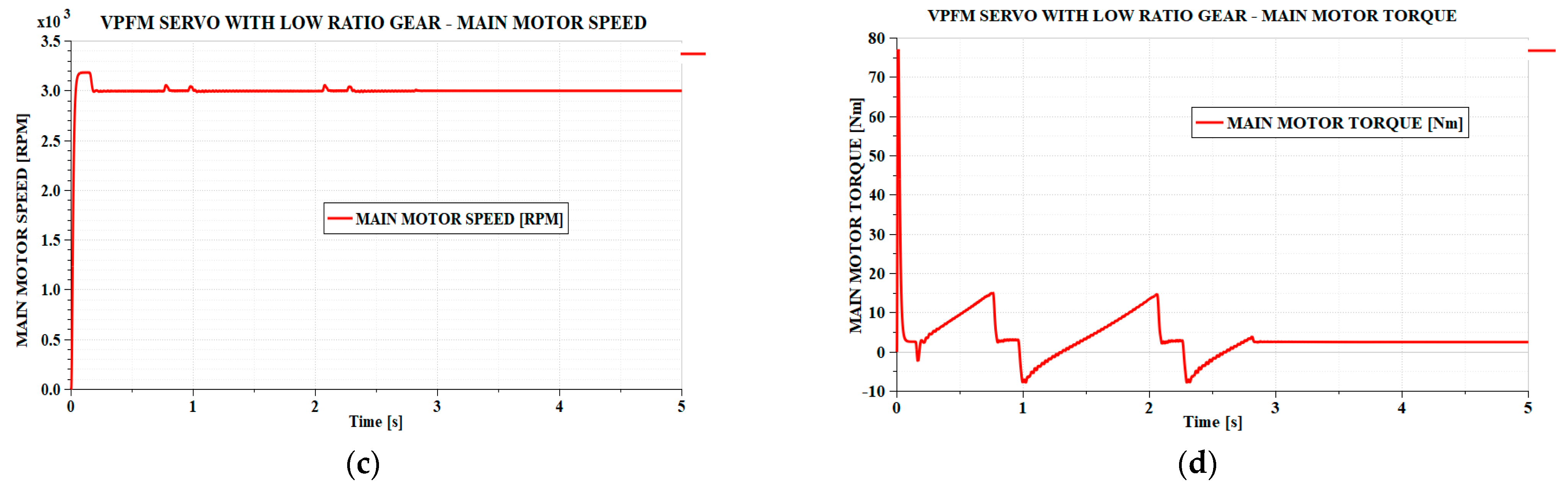
For this case, the main electric motor parameters also behave very well, with smooth variations, without significant oscillations. The maximum power consumed is approximately 5.2 kW, being absorbed mostly by the main engine. Regarding the power consumed, it is noted that at idle, with zero aileron steering, there is a permanent power consumption of 900 W.
The problems related to large parameter oscillations are transferred to the command motor in this case. Although the command voltage has a smooth variation, the current, shaft torque, angular velocity, and power absorbed by the command motor exhibit strong oscillations. Although the command power has small peaks, on the order of 25 W, the large current variations still place intense loads on the command converter this time. But considering that the commanded power is over 250 times smaller, such a converter is still easier to design and build.
These oscillations in the command system are due to the moment pulsations that occur on the pump plate. Each piston of the pump, during one rotation of the pump drive shaft, is alternately in the suction phase and then in the discharge phase. So, the force exerted by each piston on the pump plate will have a pulsating variation with a frequency equal to the pump rotation speed. The frequency of the moment that appears on the pump plate will be equal to the pump rotation speed multiplied by the number of pistons.
Large torque and angular velocity oscillations place intense loads on the gear reducer. This leads to rapid wear and short service life. However, from a constructive point of view, this gear reducer can be designed as an interchangeable module, to be replaced after a certain number of flight hours, before its performance declines to affect the quality of the aileron actuation.
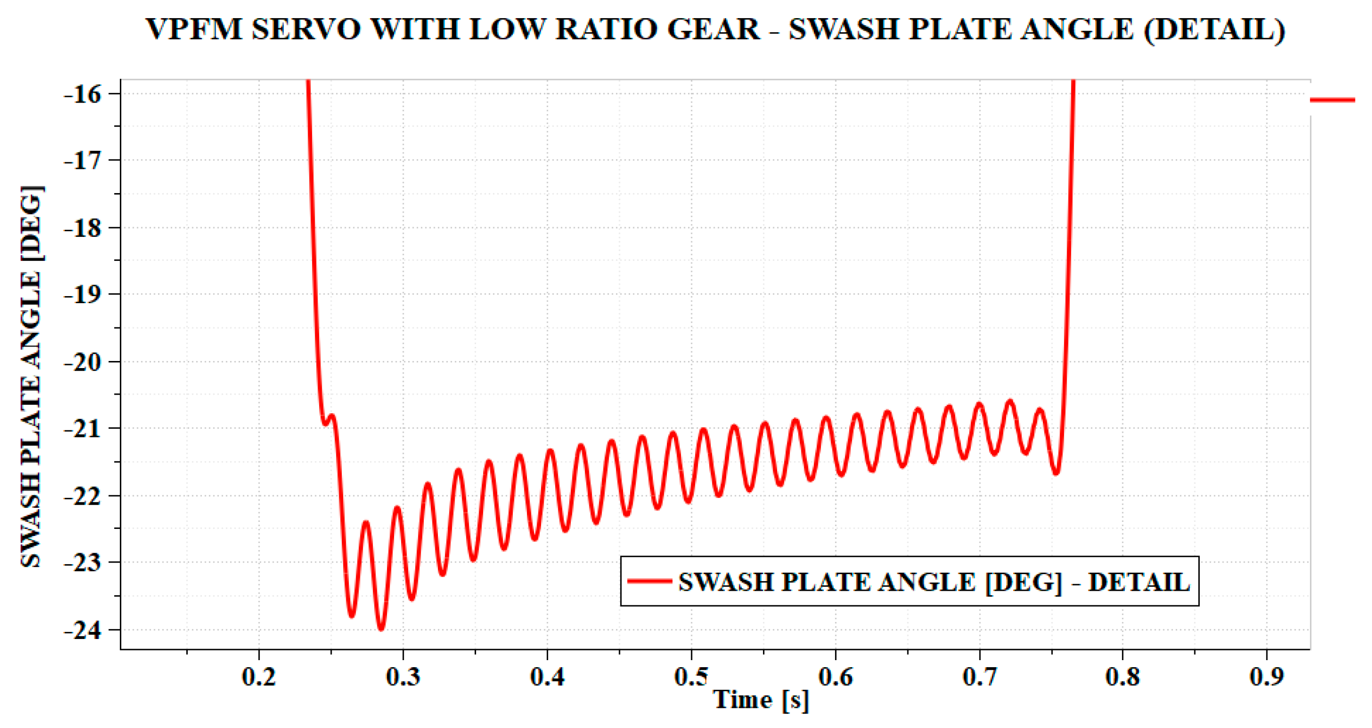
The large pulsations of the pump plate’s operating torque also translate into oscillations. These are very small, hard to notice in
Figure 7f, but are highlighted in
Figure 8.
The shaft torque of the command motor is of the order of 0.9 Nm, and the maximum angular velocity of this motor is of the order of 300 rpm. These parameters fit very well into the characteristics of a stepper motor. For example, the NEMA 23 motor, produced by GEMS Motor, variant GM57HSM76-3004 in bipolar configuration offers a maximum torque of 1.5 Nm and can reach a maximum speed of 300 rpm under the conditions of having a mass of 1.05 kg [
24]. The use of stepper motors in this situation has the advantage of very precise control of the pump plate under conditions of a high holding torque, which can compensate for the torque pulsations occurring on the pump plate.
There is a problem with the characteristics of a variable cylinder capacity pump of similar size. Parker manufactures small cylinder capacity motor-driven axial piston pumps for aviation. In this regard, the AP05V pump has a cylinder capacity of 0.15 in
3/rev, a maximum rotation speed of 11,000 rpm and weighs approximately 1.2 kg, but it has a constant cylinder capacity [
25]. One of the smallest variable cylinder capacity pumps produced by Parker is the PV016, which has a cylinder capacity of 16 cm
3/rev, a maximum rotation speed of 3000 rpm, and a nominal pressure of 350 bar and weighs 19 kg [
26]. Its control method, however, is not of the type considered in this paper, but has internal displacement regulators. We can estimate that for a smaller cylinder capacity of only 3.5 cm
3/rev, with a simplified control system, with a special aviation-designed gear, the weight of the pump could be reduced to up to 5 kg.
In this case, the additional mass added to the basic elements of the servoactuator system, also considered in the previous section, is composed of the mass of the stepper motor of 1.05 kg and the mass of the variable cylinder capacity pump of 5 kg: a total of 6.05 kg, compared to only 1.14 kg in the case of the FPVM servoactuator.
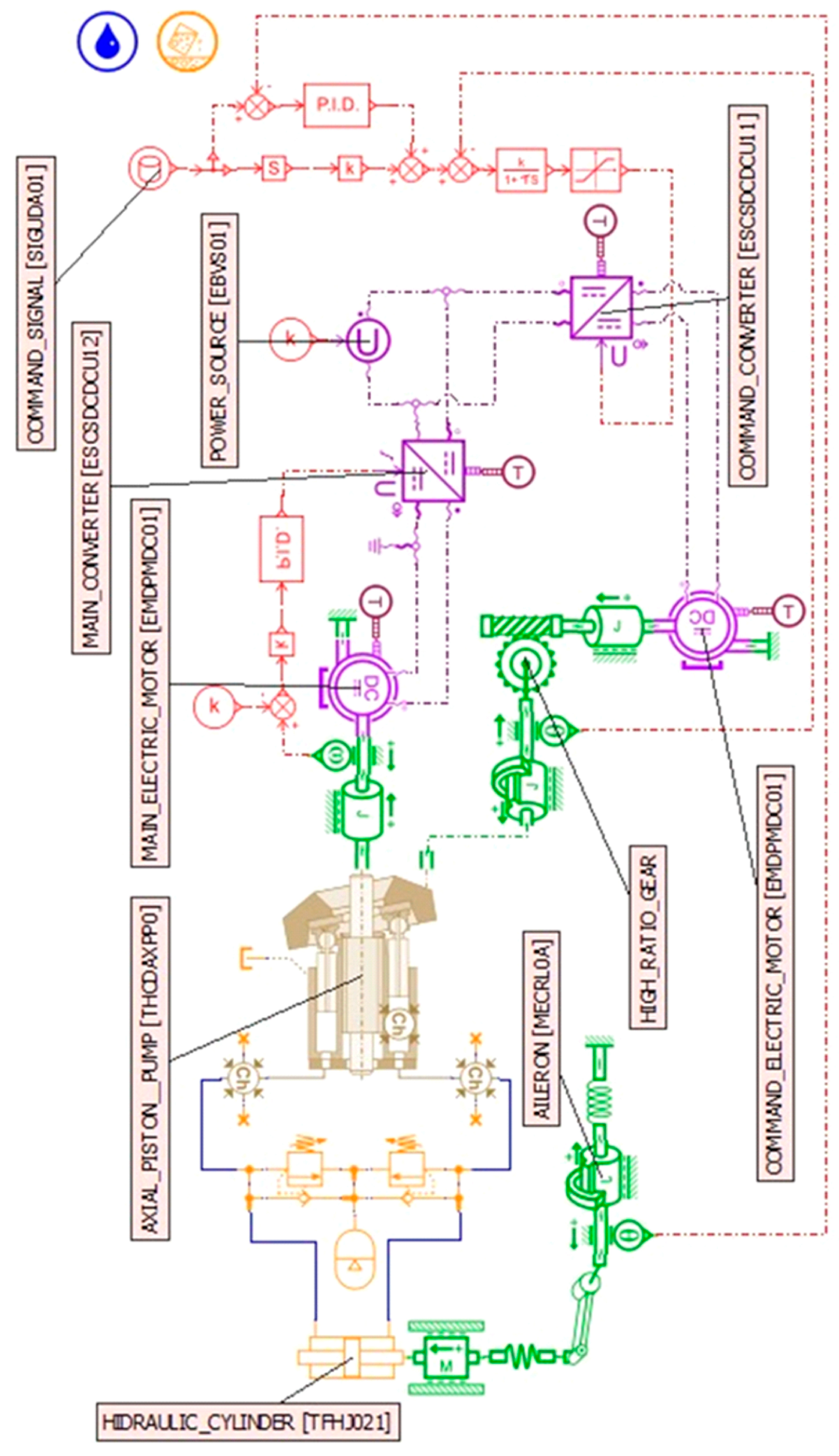
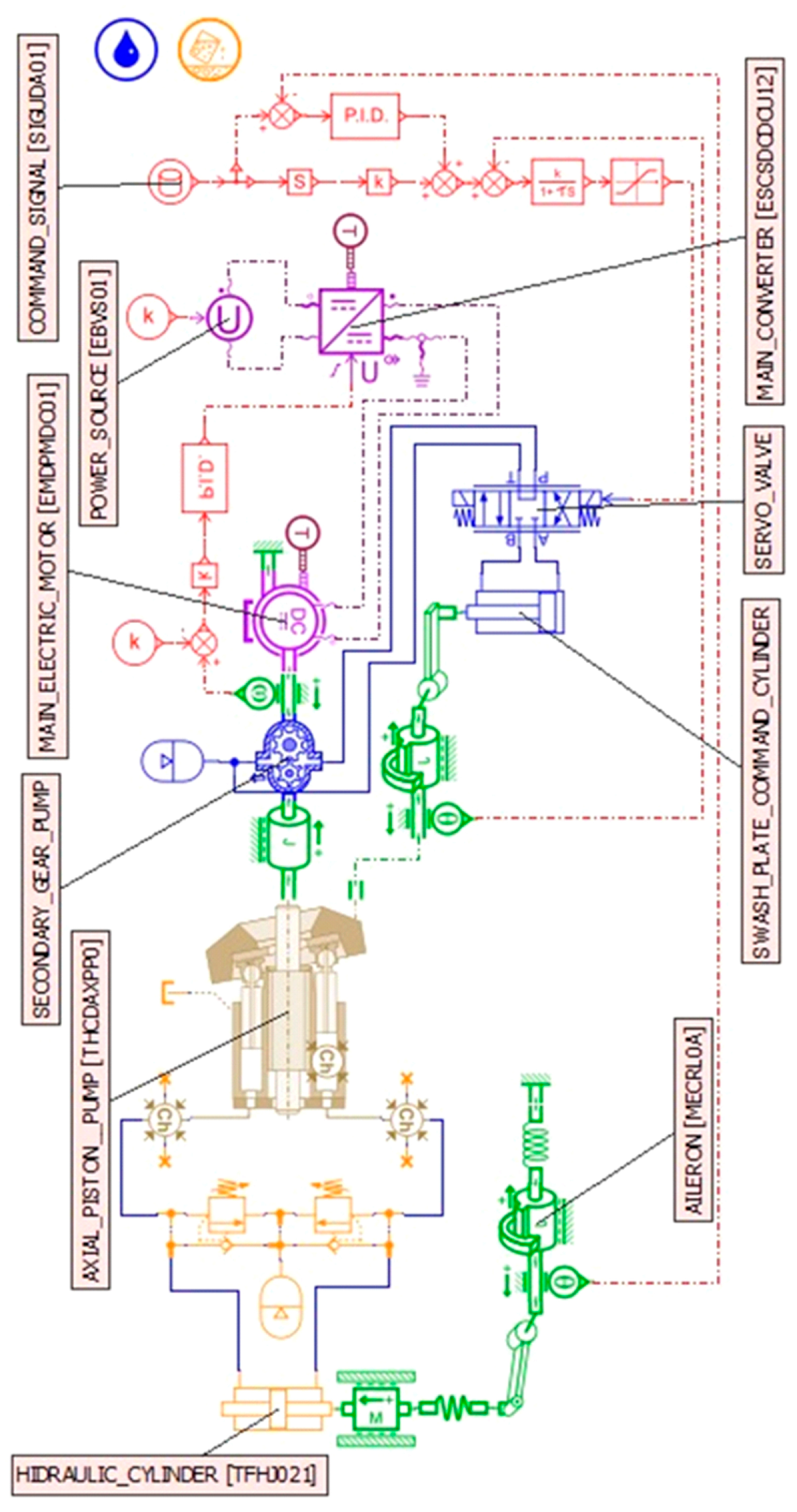
4. VPFM Type EHA with High Transmission Ratio to Command Pump Displacement—(VPFM–HR)
This case is similar to the previous one, but the pump plate is driven by a worm–worm wheel type gear with a high transmission ratio. Its scheme is shown in
Figure 9.
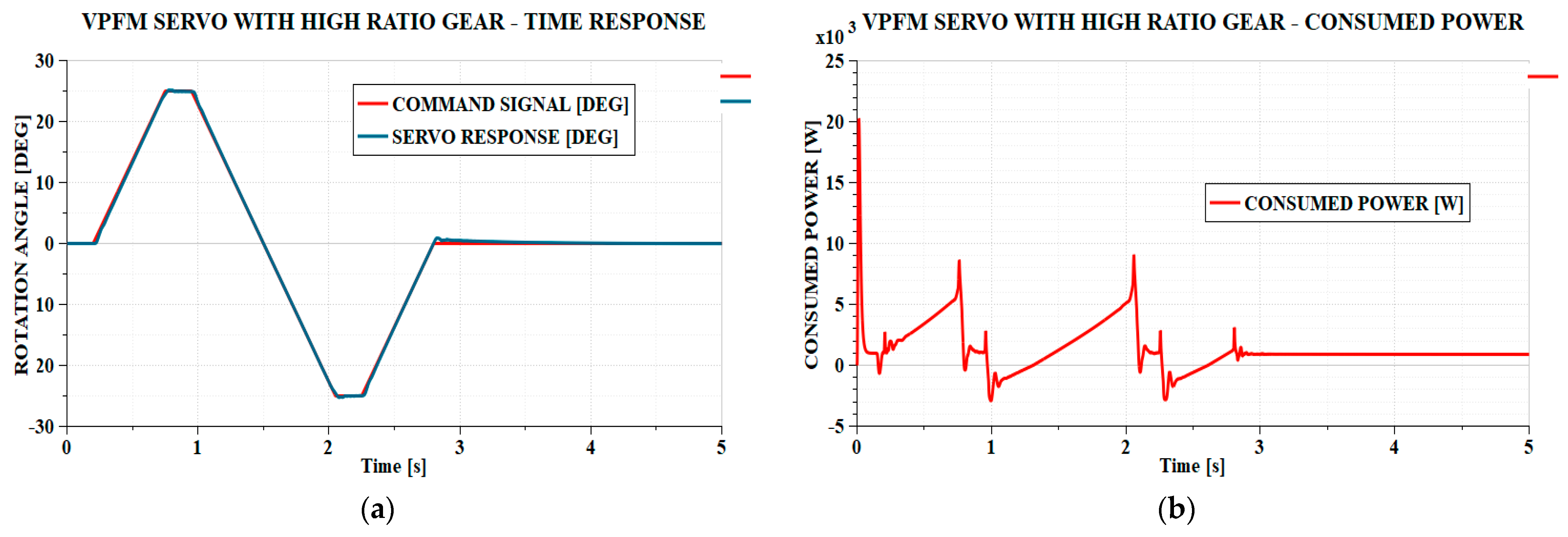
This time, a worm–worm wheel gear transmission ratio of 70 was considered. The simulations results are presented in
Figure 10,
Figure 11 and
Figure 12.
In
Figure 10, the time response of the servoactuator is very good. The positioning error is below 0.5° and the time delay is below 0.04 s throughout the entire simulated sequence. The power consumed is approximately the same, except for power peaks that can reach values of approximately 9 kW, when the servoactuator reaches its maximum stroke.
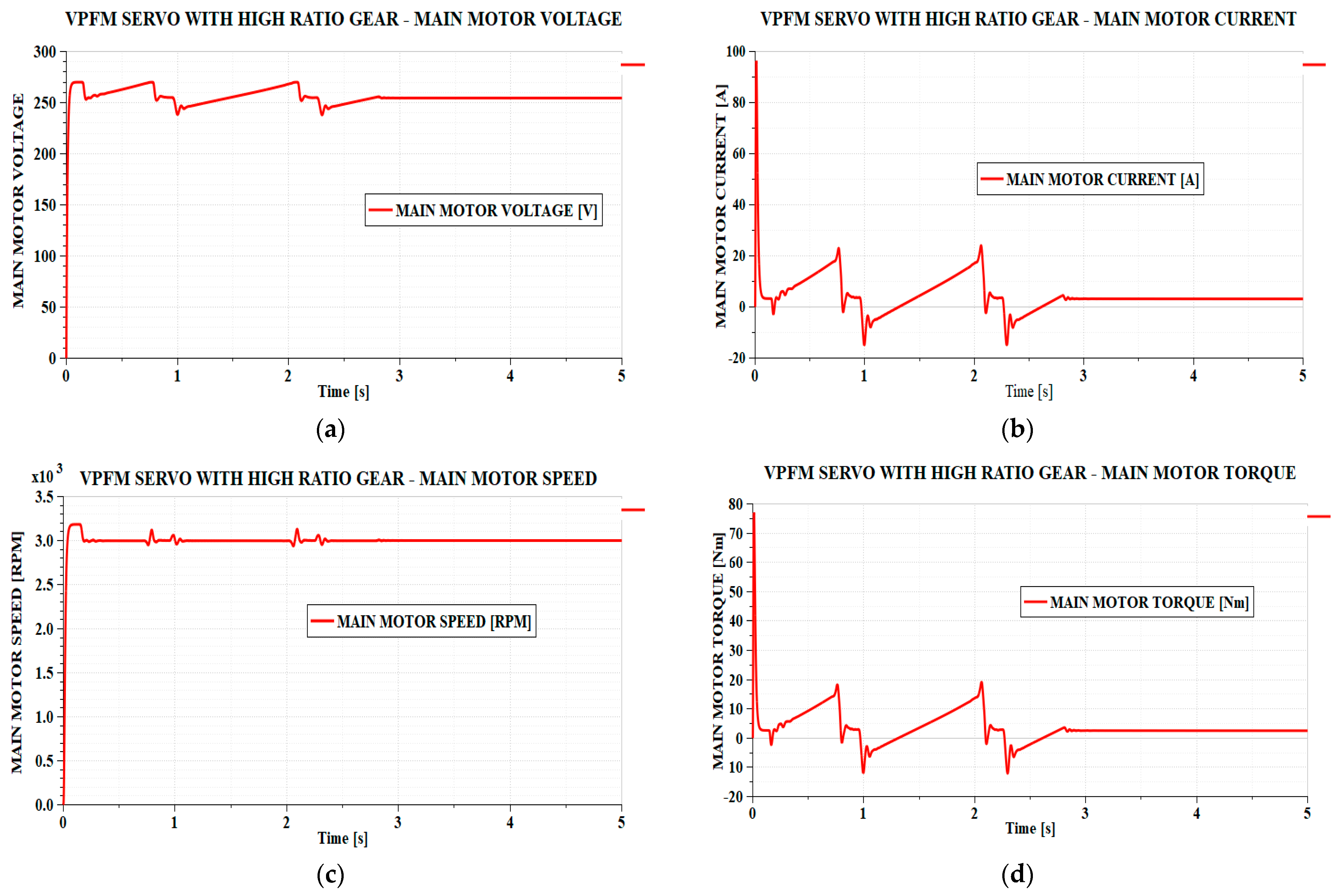
In
Figure 11, it is observed that the variations of the main motor parameters are smooth, due to a lower load on it. The rotation speed is maintained very close to the constant value of 3000 rpm and the command voltage, command current, and torque of the main motor do not have pronounced peaks or oscillations.
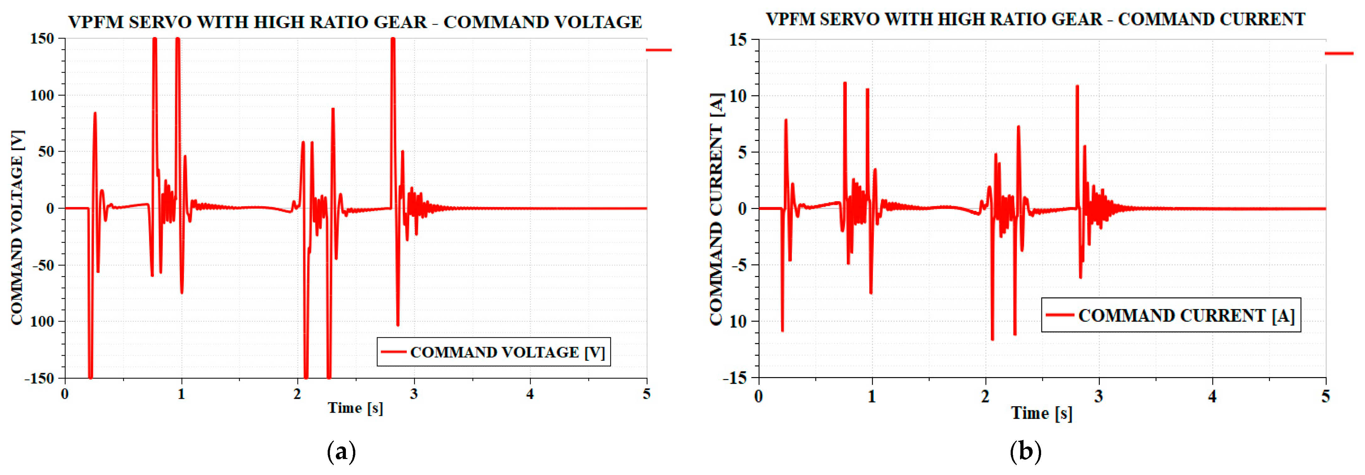
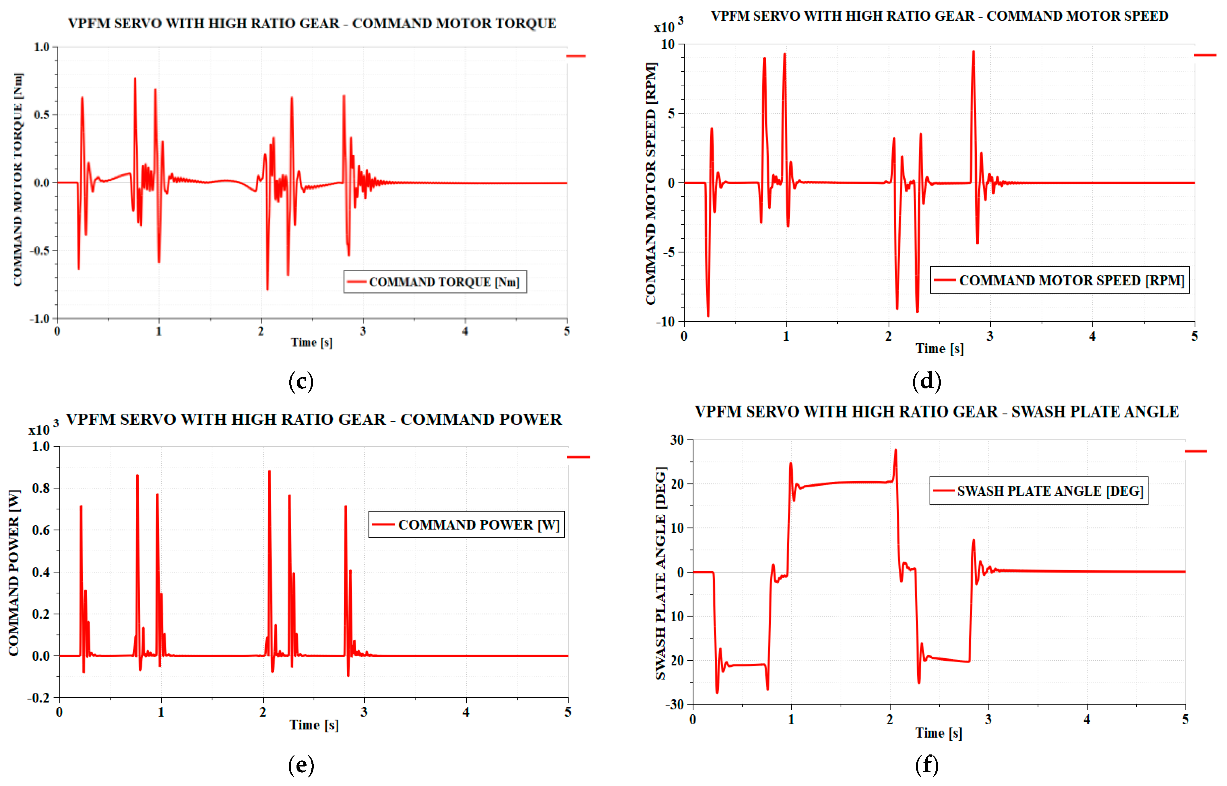
The parameters of the command motor (see
Figure 12) also have a relatively good behavior, without strong oscillations, as in the previous case. However, large peaks of voltage, current, torque, and rotation speed appear in moments of sudden variation of the command signal. These moments of time involve rapid variations in the angle of the pump plate and, therefore, high rotational speeds of the command motor. Peak speeds of around 9000 rpm are reached with peak shaft torques of around 0.5 Nm, which means peak power of up to approximately 900 W. A BLDC motor that has a rotation speed of 13,000 rpm and a power of 1200 W and weighs approximately 1.2 kg is the BLB 1200 motor from the company Xuperb from Guandong, China [
27]. However, an open problem remains: whether such a motor can withstand the rapid rotation speed variations necessary for the functioning of a servoactuator of the studied type.
The worm–worm gear reducer configuration ensures a high transmission ratio and very good attenuation of torque pulsations coming from the pump plate, but it also creates higher friction. The very good attenuation of the moment oscillations coming from the pump plate makes the variation in the pump plate angle sufficiently smooth, without oscillations, presenting only a few relatively small peaks in the moments of rapid variation of the pump plate angle. Again, there is the problem of wear over time due to the high loads to which it is subjected, and a possible solution is also to make the reducer in the form of an interchangeable module that can be replaced after a certain number of flight hours.
The power consumption is similar to the power in the previous case, except for the higher power peaks that reach 8.7 kW. The power consumption at idle is approximately 900 W.
It is assumed that the axial pistons pump has the same characteristics as the pump in the previous case. Consequently, in terms of additional mass compared to the common elements of the schemes, this consists of the pump mass, which was approximated at 5 kg, and the command motor mass, estimated at 1.2 kg: in total, 6.2 kg.
5. VPFM Type EHA with Hydraulic Command of Pump Displacement—(VPFM–HYD)
As seen in the previous sections, either high torques or high rotation speeds of the electric motor are required to command the pump plate. A variant that combines these advantages is that of hydraulic command of the pump plate. However, this requires an auxiliary hydraulic circuit. A VPFM-type EHA scheme that uses this variant is shown in
Figure 13.
A hydraulic circuit consisting of a pump, a hydraulic accumulator acting also as a reservoir, a servo valve, and a hydraulic cylinder is used to command the pump plate. In order to avoid the difficulties related, on one hand, to the presence of an additional motor to drive the auxiliary pump, and on the other hand, to its control, which again involves rapid rotation speed variations, the option of mounting the auxiliary pump on the same shaft as the main pump was chosen. In this way, both the main and the auxiliary pump are permanently maintained at a constant rotation speed. The hydraulic cylinder for driving the main pump plate is controlled by a servo valve which, in the neutral position, returns the input flow to the tank. This allows the auxiliary pump to operate at a constant rotation speed.
The command servo valve has the advantage of achieving very good dynamics of the plate command system, but it also has some disadvantages. Servo valves are expensive electro-hydraulic devices, but they have low reliability. It is known that of all hydraulic devices, servovalves have the lowest reliability.
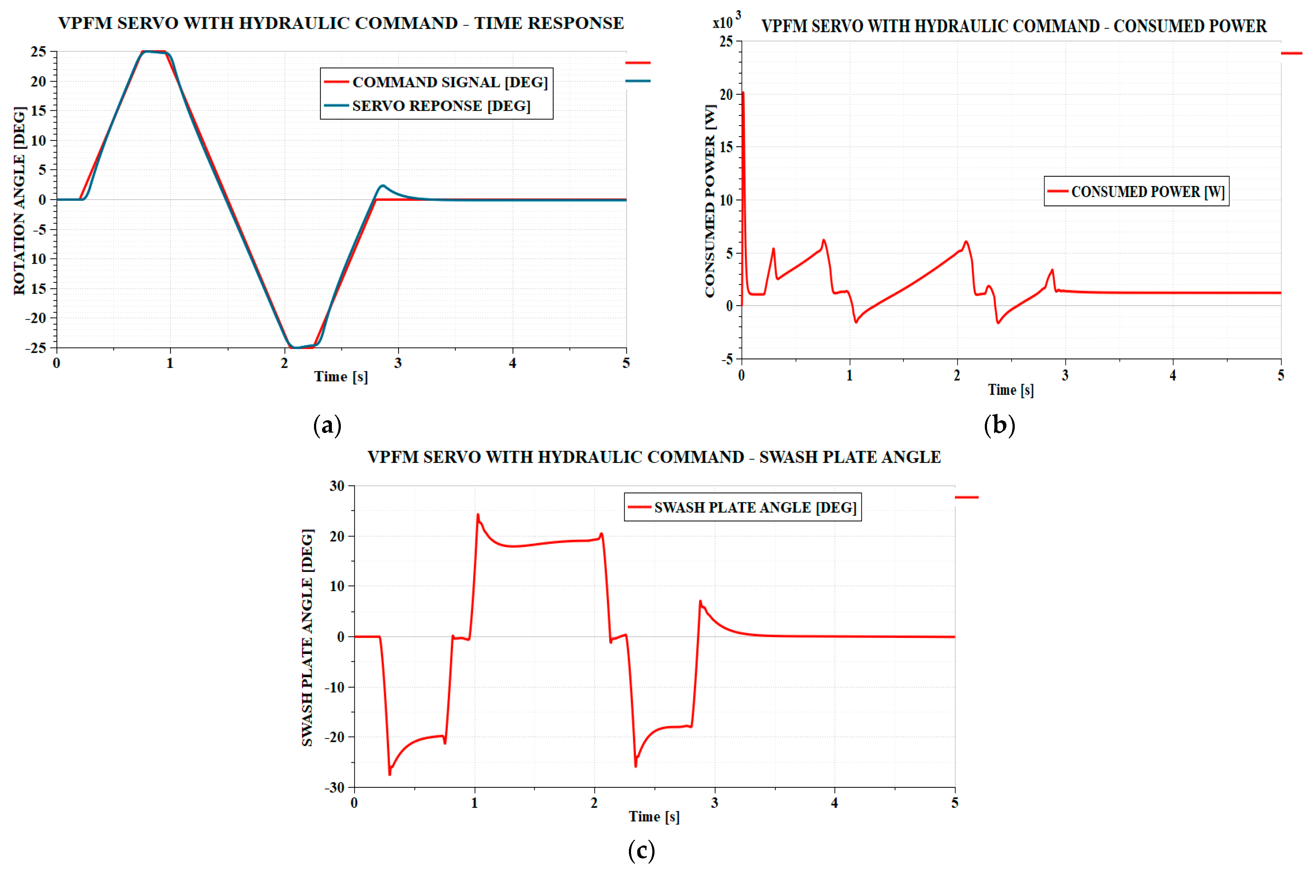
From the point of view of the servoactuator dynamics, a very good behavior is observed, which follows the command signal almost perfectly, except for the area where the aileron movement stops at the end of the last ramp signal where a maximum error of approximately 2° appears, which exceeds the maximum allowed value for an interval of approximately 0.2 s. If the automatic control scheme of the pump plate is refined, it is possible to eliminate this inconvenience. The force, speed, and rigidity of the hydraulic drive of the main pump plate make it possible to obtain such dynamics. The variation of the angle of the pump plate is smooth, without any vibrations due to the superior rigidity provided by the hydraulic cylinder compared to that achieved with the help of an electric motor (variants in
Section 3 and
Section 4).
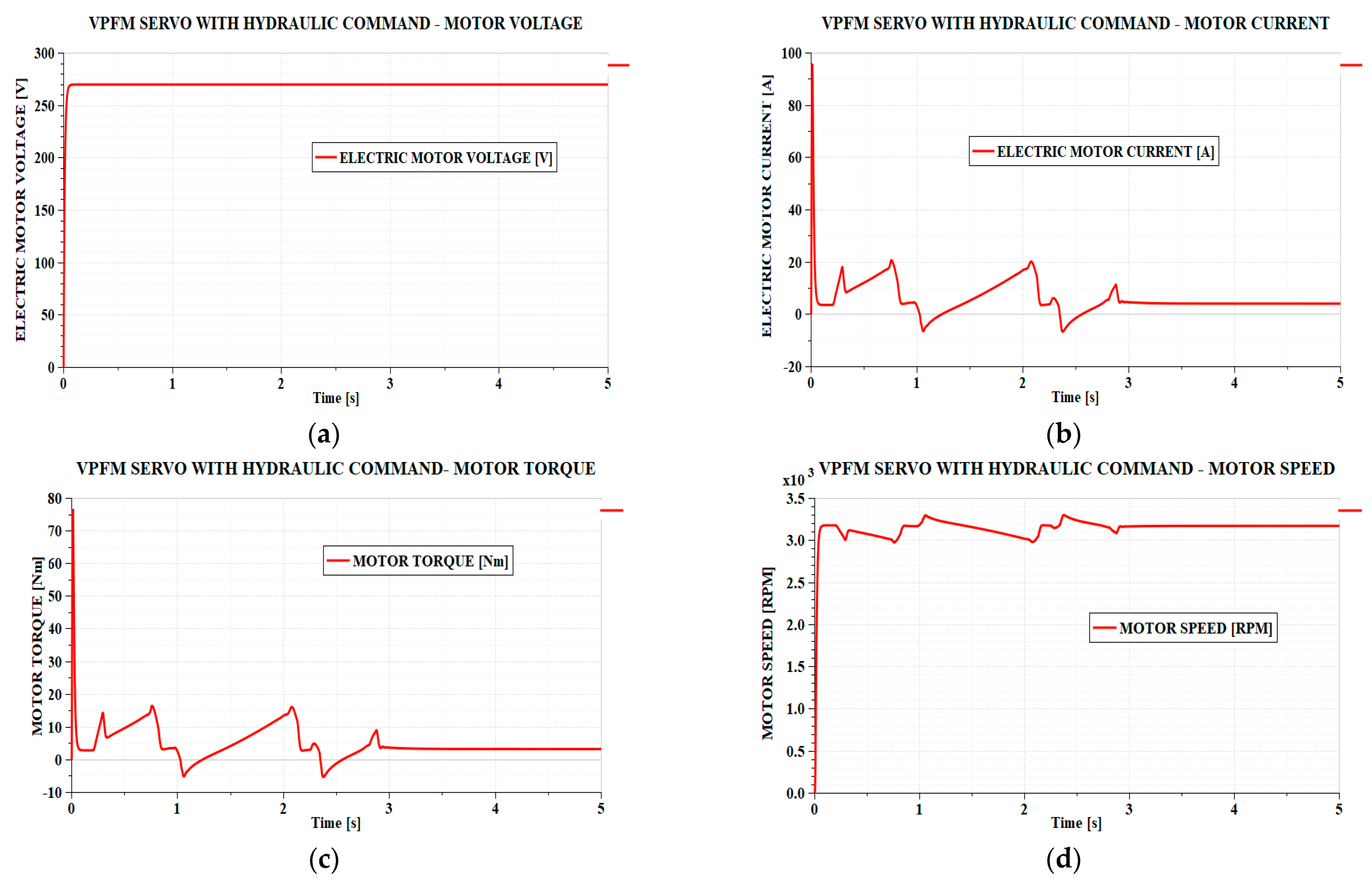
The maximum power consumed is approximately 6.3 kW, and the power consumed at idle is approximately 1200 W. Hence, from the point of view of the power consumed, this servoactuator has a significant disadvantage.
Regarding the components used, the main pump remains the same as in
Section 3 and
Section 4, for which we considered a mass of 5 kg. To this, the auxiliary pump is added, having a cylinder capacity of approximately 2.2 cm
3/rev. Being a constant-speed gear pump, a pump of the same category as the FPVM servoactuator pump can be used. According to [
23], an SNP1NN pump meets the operating conditions in this servoactuator and weighs 1.05 kg. The auxiliary circuit hydro-accumulator can be of the same type as the main circuit. It weighs 1.4 kg. The required servo valve is very small. In [
28], micro electrohydraulic servo valves produced by MOOG Inc. from Elma, NY, USA, series 31, are presented. The servo valve 031-1001 has a reference flow rate of 2.5 lpm, as much as was considered for the servo valve in the simulation scheme and weighs 0.37 kg. For the hydraulic cylinder, a piston diameter of 25 mm, a rod diameter of 12 mm, and a stroke of 25 mm were considered. Because the mass of hydraulic cylinders depends on the stroke for which they are built, the catalogs of manufacturing companies do not usually specify their mass. This is determined based on the customer’s requirements. We evaluate for the hydraulic cylinder mentioned above a mass of 0.15 kg. In total, the elements that appear in addition to those common to the other servoactuators result in a mass of 7.97 kg.
6. Comparative Synthesis of Results
From what was presented in the previous sections, it can be seen that each variant studied has advantages and disadvantages, so that
Table 4 presents a comparative synthesis between the variants studied.
Regarding the mass of the servoactuator, the mass of the common elements in the four studied schemes is denoted by C. An estimate of this mass can also be made, taking into account their dimensions or the values presented in the catalogs.
The hydraulic cylinder used has a piston diameter of 78 mm, a rod diameter of 38 mm, and a stroke length of 45 mm. We can estimate the mass of this hydraulic cylinder at 2.5 kg. The mass of the one-way valves presented in the catalog is 10 g each; the mass of the relief valves is 0.3 kg each. The mass of the hydraulic accumulator is 1.4 kg. As the main motor, a compatible variant is the BLDC motor type BG95x120 dPro PN/EC/EI produced by AMETEK, which, when powered by a voltage of 60 V, has a maximum power of 4400 W and a nominal rotation speed of 3900 rpm and weighs 6.7 kg [
29]. In total, the mass of the common components of the servoactuators results in C = 11.2 kg.
If we consider the power consumed by the servoactuators, the following observations can be made. The FPVM servoactuator has a peak power of the order of 5.2 kW, on top of which oscillations due to the flow pulsations of the pump are superimposed, reaching peak values of 8 kW. The peak value without oscillations is a convenient one compared to other servoactuators, but the problem of power peaks remains. The power consumed at idle is the most advantageous for the FPVM-type EHA, of only 5 W, because here, the pump is practically stopped, and only residual power is consumed. The other types of EHAs have high idle power consumption because the pumps remain permanently engaged. This high power consumption leads to continuously questioning of their implementation on transport aircrafts. After a cruise flight lasting several hours, the energy consumed in idle or low-load modes reaches extremely high values, incompatible with current trends in reducing energy consumption. Given their much better response time than the FPVM-type EHA, the VPFM-LR and VPFM-HR EHAs would be compatible with aerobatic or advanced training aircraft, where idle modes represent a small fraction of the total flight. The good dynamic qualities, very low oscillations of the electric motor parameters, and good reliability could justify their use on these aircraft.
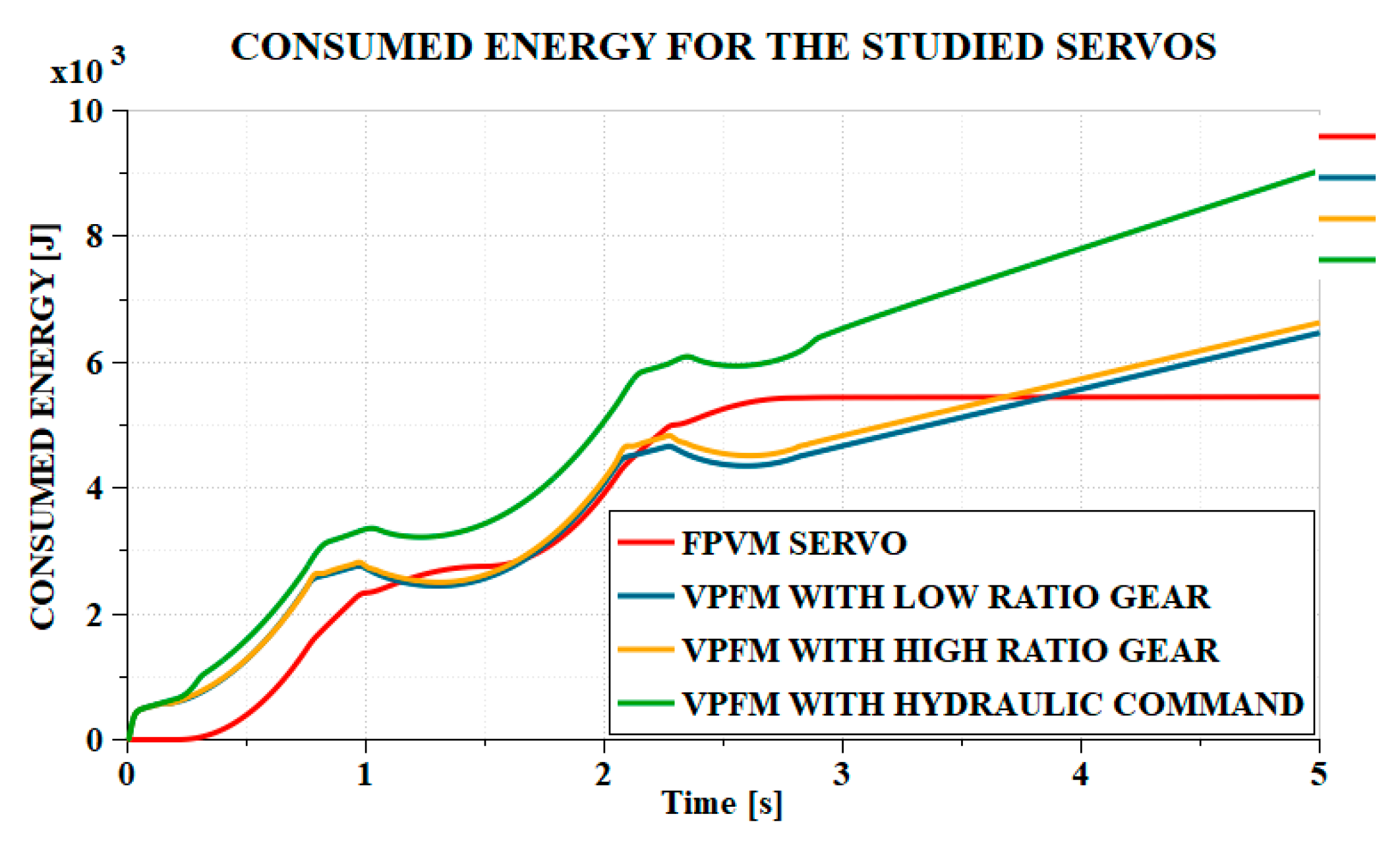
These considerations are also justified by the results in
Figure 16. It is observed that when idling, the FPVM-type EHA has negligible energy consumption, but during loads, the energy consumed increases much faster than in the VPFM-LR and VPFM-HR types. The load sequence begins with an idle interval, in which the FPVM does not consume energy, but the VPFM consumes a considerable amount of energy, after which, during load, the energy consumed by the FPVM becomes greater than the energy consumed by the VPFM-LR and VPFM-HR. At the end of the load sequence, when there is a new idle interval, again, the energy consumed by FPVM becomes less than that consumed by VPFM.
VPFM-HYD-type EHAs have the best dynamics and the lowest loads on the electric motor, but the energy consumption is very high, both under load and at idle. In addition, the use of servovalves in the system greatly reduces the reliability of the system. Redundant configurations could be achieved, but this type of EHA already has a much higher mass than the others. Another option would be the variable pump variable motor (VPVM) version, which would reduce the energy consumed in idle modes. There are studies in the literature on such configurations [
15,
16,
30], but the control strategies are very complex. Great control difficulties are to be expected when the system switches from idle to fast loads, when the motor must be accelerated if it has been stopped at idle and, in addition, the pump cylinder capacity must be increased.
Regarding reliability, the studied EHAs can be considered here as well. For the EHA-FPVM, the studied schemes contain highly reliable devices—an electric motor, gear pump, valves, hydraulic cylinder. These components generally give a low number of failures. Problems may arise, however, in the components of the electrical power converter. It must withstand large current oscillations. In fact, such a problem was also highlighted in [
6]. For this reason, the reliability of this type of FPVM EHA may be lower than might be expected from the studies presented in this paper. For the VPFM-type EHA, some components are used that have a lower reliability than those in the FPVM system. Variable axial piston pumps typically have a lower reliability than gear pumps. The gears for commanding the plate, whether high or low ratio, are highly loaded. The friction in these gears causes intense wear and they will be put out of service in a relatively short time. Replacing the solution of interchangeable modules after a certain number of flight hours seems reasonable in this regard. As previously mentioned, VPFM-HYD EHAs contain components with lower reliability. Along with the components found in the VPFM-LR and VPFM-HR variants, there is also the servo valve, which is recognized in the literature as having considerably lower reliability than the other components of the hydraulic system.
7. Conclusions
Adopting a certain EHA version for a certain type of aircraft is a rather difficult decision, taking into account a multitude of aspects. For aviation, the control quality and flight safety are crucial. However, the issue of energy saving has been rapidly growing in importance nowadays and it is no longer an issue to be neglected.
Currently, the dominant EHA version in aircraft flight controls is FPVM. Its main problem is the high demand upon the electric power controller, due to the high electric motor power and frequent changes in speed and direction. VPFM versions studied in this work eliminate the problem at the cost of raising additional issues.
The main problem in this study, for the VPFM versions, is the high power consumption in idle mode. All these versions keep the axial piston pump rotating all the time and this means a permanent power consumed and lost in the idle regime. This power is much higher in the VPFM-HYD version.
From this point of view, future research is to realize an EHA scheme in a hybrid configuration. This means the EHA operates in VPFM mode when the flight controls are intensely used. When the flight controls are in idle mode for long periods, the electric motor is stopped. A sudden command of the flight controls is supported by a hydro-accumulator until the electric motor starts and enters in the nominal regime. This solution is feasible considering the electric motor needs to start 1–2 s until it reaches the nominal regime. The starting can be made in no-load conditions to have the smallest possible peak currents in the period until the nominal regime is reached. In this way, these EHA versions are very interesting for airliners on long flights.
Another problem that appears in the VPFM-LR and VPFM-HR versions is the transmission mechanism wearing. This wearing increases the clearance in the transmission and further produces a bad control for the pump swash plate and, finally, an altered control for the aileron or any other flight control. A solution is to design the transmission mechanism as an interchangeable module, easy to replace after a number of flight hours. Adopting solutions based on more thorough maintenance and reducing the number of hours when some components are overhauled may, in the future, be a solution for the use of technical solutions that, until recently, were known to have lower reliability. The presence of redundant servoactuators on the flight controls of transport aircraft is another solution used for a long time. This solution reduces the risks if one flight control EHA fails.
A study, in the future, is the influence of the transmission mechanisms wearing upon the EHA functioning. It is interesting to determine the clearance limits between the transmission parts that are acceptable in the EHA functioning. Using numerical models, it is possible to find the clearance limits acceptable for a convenient flight control and, by experimental studies, it is possible to determine the number of flight hours until these limits are reached.
From the wearing point of view, the VPFM-HYD version is the most appropriate. It has no mechanical transmission to control the swash plate, so it does not have this problem. Another important advantage is the dynamic quality. On the other hand, a big disadvantage of this scheme is the high power consumption. For fight airplanes where the quality of flight controls is essential, and the flight controls are hardly used, with short periods in idle regime, this version can be used. Due to short periods in idle regime, a hybrid version, as mentioned before, brings insignificant advantages, so the VPFM-HYD version could be used in this form.
A solution that follows to combine the advantages of FPVM and VPFM is VPVM (variable pump variable motor). The study of VPVM-type configurations needs to be detailed in the future in order to fulfill the aircraft control requirements. However, the difficulties encountered are expected to be high. Until now, there has been some research in this field [
16], but the control of this kind of system is very complex.


 ,
, 
