Article

Research on Active Lubrication Based on Piezoelectric Micropump

1
Henan Key Laboratory of High—Performance Bearings, Luoyang 471039, China
2
School of Mechanical and Automotive Engineering, Qilu University of Technology, Jinan 250316, China
3
School of Mechatronics Engineering, Harbin Institute of Technology, Harbin 150001, China
*
Author to whom correspondence should be addressed.
Actuators 2025, 14(5), 227; https://doi.org/10.3390/act14050227
Submission received: 5 April 2025 / Revised: 28 April 2025 / Accepted: 1 May 2025 / Published: 2 May 2025
(This article belongs to the Special Issue Piezoelectric Ultrasonic Actuators and Motors)

Abstract

This paper mainly introduces the problem of active lubrication. At present, the technology of active lubrication for bearings in micro-space is not mature, and it is difficult to meet the requirements of micro-space lubrication. A piezoelectric micropump for active lubrication is proposed in this paper. The micropump has the advantages of compactness, embedding, high precision, and fast response. We analyze the performance of the micropump under different characteristics. When the applied frequency is 9.95 kHz, the voltage is 200 V and the oil viscosity is 0.001 Pa·s, and the pumping capacity can reach 0.8 μL. When the same excitation signal is used, the experimental pumping capacity reaches 0.76 μL. The theoretical and experimental error is 5.3%. For different bearing conditions, combined with the theoretical model of minimum oil film thickness, we propose the number of pulses to meet the micro-redundancy lubrication under different working conditions. These analyses provide a theoretical basis for active lubrication in micro-space.

1. Introduction

In today’s era, the failure of equipment in many fields is caused by the lubrication failure of bearings. So, it is necessary to solve the problem of bearing lubrication. Bearing lubrication is of great significance to improve the service life of equipment, which is a development trend in the future. However, the active lubrication of small spaces remains to be solved [1]. Lubrication systems can be divided into passive lubrication systems and active lubrication systems. The passive lubrication system is driven by centrifugal force or surface migration force to add lubricant to the bearing. Passive lubrication equipment includes the oil rope supply system [2] and the porous lubrication system [3]. As a passive lubrication method, porous self-lubrication has good reliability. However, its oil supply accuracy is lower than that of active lubrication [4]. Grease lubrication is a passive lubrication method. In the space environment of large temperature difference and high vacuum, it has poor controllability and weak adaptability [5]. The passive lubrication system is uncontrollable. It cannot provide lubricating oil in time according to the wear state of the bearing at that time. The active lubrication system provides the required lubricant to the bearing by receiving external commands. It includes an on-site on-demand oil supply system [6] and static oil storage system [7]. In summary, active lubrication can better meet the needs of bearing lubrication. Estupinan et al. [8] proposed a piezoelectric actuator. It achieves active lubrication by controlling the valves of complex high-pressure oil injection systems. Its size is 30 mm. It arranges the piezoelectric actuator along the radial direction at the outer surface of the target bearing. The active lubrication method based on electromagnetic actuator can obtain better accuracy, but it is susceptible to disruption by space electromagnetic interference; additionally, the whole lubrication system is complex [9]. Morosi and Santos [10] proposed an active control method for gas-lubricated journal bearings. This method is achieved by controlling the valve through a piezoelectric actuator. The system is also too complex and large. Santos [11] proposed a method to realize active lubrication of bearings by using traditional hydraulic systems. A high-pressure oil storage system with valves is installed outside the bearing system. However, the whole system structure is complex and takes up a lot of space. This type of active lubrication system selects a drive structure that is more suitable for working in a large space environment. However, this structure has low precision, large single oil supply, and slow response speed. Therefore, it cannot achieve accurate and fast lubrication in a small space. In general, our oil requirement is at the μL level. There are also related studies [12] showing that the oil requirement is at the μL level. At the same time, we calculated the oil demand according to the formula we proposed. The oil requirement is really at the μL level.
Different from the above driving principle, a piezoelectric micropump structure is proposed in this paper. We use piezoelectric ceramic materials. Piezoelectric material is a kind of material with non-centrosymmetric structure. This material has the ability to enhance electrochemical and photochemical activity in response to mechanical deformation [13]. Piezoelectric actuators have been widely used in the field of microfluidic manipulation [14,15,16,17]. The piezoelectric micropump uses the volume change of the resonant cavity generated by the vibration of the piezoelectric actuator to accurately drive the microfluid. It has the advantages of high control precision, simple structure, and good stability. It is widely used in many fields of precision fluid control, such as military, industrial, medical, and other fields [18,19]. Compared with traditional mechanical pumps, piezoelectric micropumps have the advantages of simple control mode, high pumping efficiency, fast response speed, and strong anti-electromagnetic interference. When the corresponding driving voltage amplitude is applied to the piezoelectric micropump device, the precise delivery of the fluid can be achieved [20,21,22]. Piezoelectric micropumps are divided into valve piezoelectric micropumps and valveless piezoelectric micropumps. In 2023, Zhang Lu et al. from Northeast Forestry University proposed a self-cleaning filtration and pumping system based on the piezoelectric micropump. The system can simultaneously achieve stable and long-term directional filtration and pumping [23]. The valveless piezoelectric micropump will produce backflow problems. Therefore, it cannot achieve full forward flow [24,25]. For the piezoelectric micropump with a valve, according to the type of check valve, it can be further classified into cantilever valve, fixed valve at both ends, wheeled valve, spherical valve, and so on [26]. In 2019, Liu et al. [27] of Nanjing University of Aeronautics and Astronautics optimized a piezoelectric air pump. They improved the performance of the pump by 32.9%. In 2018, Sun Yeming et al. [28] proposed an active valve-type piezoelectric pump with two-way transmission through the coordinated control of the active valve and the piezoelectric vibrator. In 2021, He Lipeng et al. of Changchun University of Technology designed and manufactured a pump. It is a high-output-pressure piezoelectric pump with a straight arm wheel check valve [29]. The research on piezoelectric micropumps abroad started earlier than in China. Since the 1960s, with the development of microelectronic technology, foreign countries have begun to study microfluidic pumps that use piezoelectric materials to drive microfluidic flows. From the 1970s to the 1990s, with the development of piezoelectric materials and micromachining technology, the research of piezoelectric micropumps has entered a new stage [30]. The research in this stage mainly focuses on the structural design and performance optimization of piezoelectric micropumps. Until the beginning of the 21st century, micro-nano technology has developed rapidly, and the research on piezoelectric micropumps has been more in-depth [31]. In 2023, Martin Richter et al. [32] from the Fraunhofer Institute for Electronic Microsystems and Solid-State Technology in Germany designed a multi-stage connected piezoelectric silicon micropump. It uses a piezoelectric silicon micropump to pump and compress the gas, reducing the negative pressure generated. In 2004, Truong and Nguyen [33] at Nanyang Technological University in Singapore developed a wheeled piezoelectric pump with a circular plate valve using polymer lamination technology. In order to obtain broadband and large flow output performance, domestic researchers have developed many active valve piezoelectric pumps by integrating active control valves. In 2019, Bekir et al. fabricated a latch-up microfluidic valve array based on shape memory polymers. They demonstrated their applications as reagent mixers and peristaltic pumps [34]. However, the pumping performance of these valve-containing micropumps is unstable and the structure is relatively complex.
In order to improve the unidirectional flow performance of the micropump and reduce the backflow rate, we designed a piezoelectric micropump in this paper. In this paper, we design a piezoelectric micropump, which can be embedded into the micropump system to achieve active lubrication. At the same time, it can achieve high precision and fast response. Through numerical simulation and experimental verification, we studied the pumping performance, pressure generation, and control functions of piezoelectric micropumps under simulated environmental conditions. The purpose of this paper is to calculate the oil demand in advance by formula. Then, we verify that the formula is correct through experiments. We detect the friction torque of the bearing by measuring the motor current. Then, we derive the oil demand according to the friction torque. Then, we calculate the number of pulses to reflect the error. Then, we get a correct conclusion. This conclusion is that it is correct to use the formula to predict the oil demand. Through this process, the bearing realizes on-demand lubrication. Most of the previous micropumps rely on external pressure difference to drive the fluid. This system is complex and has high energy consumption. Our innovation is that micropumps work without back pressure. The micropump can realize self-priming oil supply by high-frequency vibration of the piezoelectric vibrator. and our micropumps are equipped with valve devices. Piezoelectric vibrator and valve work together to produce unidirectional fluid power. This process does not require external pressure. Then, the bearing can achieve on-demand lubrication. The results of this study will provide a reference for the development of advanced lubrication systems. At the same time, this micropump improves the accuracy and stability of the lubrication system.

2. Structure and Mechanism

The valve piezoelectric micropump device proposed in this work is shown in Figure 1. The device is mainly composed of a piezoelectric vibrator, cavity, and valve. The lubricating oil is transported and stored in the cavity through a silicone tube. We have fully discussed the selection of this configuration. The piezoelectric micropump with valve blocks the reverse flow of the fluid through the mechanical valve. The fluid achieves a strict one-way flow. However, the valveless piezoelectric micropump mainly relies on the geometric asymmetry of the flow channel to suppress the backflow. The fluid may penetrate reversely. In terms of flow control accuracy, the piezoelectric micropump with valve can achieve precise control of single displacement through the opening and closing of the valve. However, the flow rate of the valveless piezoelectric micropump is more susceptible to back pressure fluctuations. The piezoelectric micropump with active valve needs an additional drive circuit to control. It is easy to cause failure due to valve wear. The valve used in this paper is composed of a valve cover, spring, and wedge groove. The spring provides a constant reset force. It prevents the cantilever valve from opening delay and failure due to material fatigue. For ball valves and disc valves, the inertia of the ball or disc is larger. They are prone to valve opening and closing delay under high-frequency drive. However, the valve composed of a spring and wedge groove is a lightweight structure. This structure can adapt to a higher frequency drive. So, we choose this configuration of the piezoelectric micropump. The piezoelectric vibrator is the core component of the micropump device. It is composed of PZT ceramics and copper sheets, and is fixed on the cavity by epoxy resin.
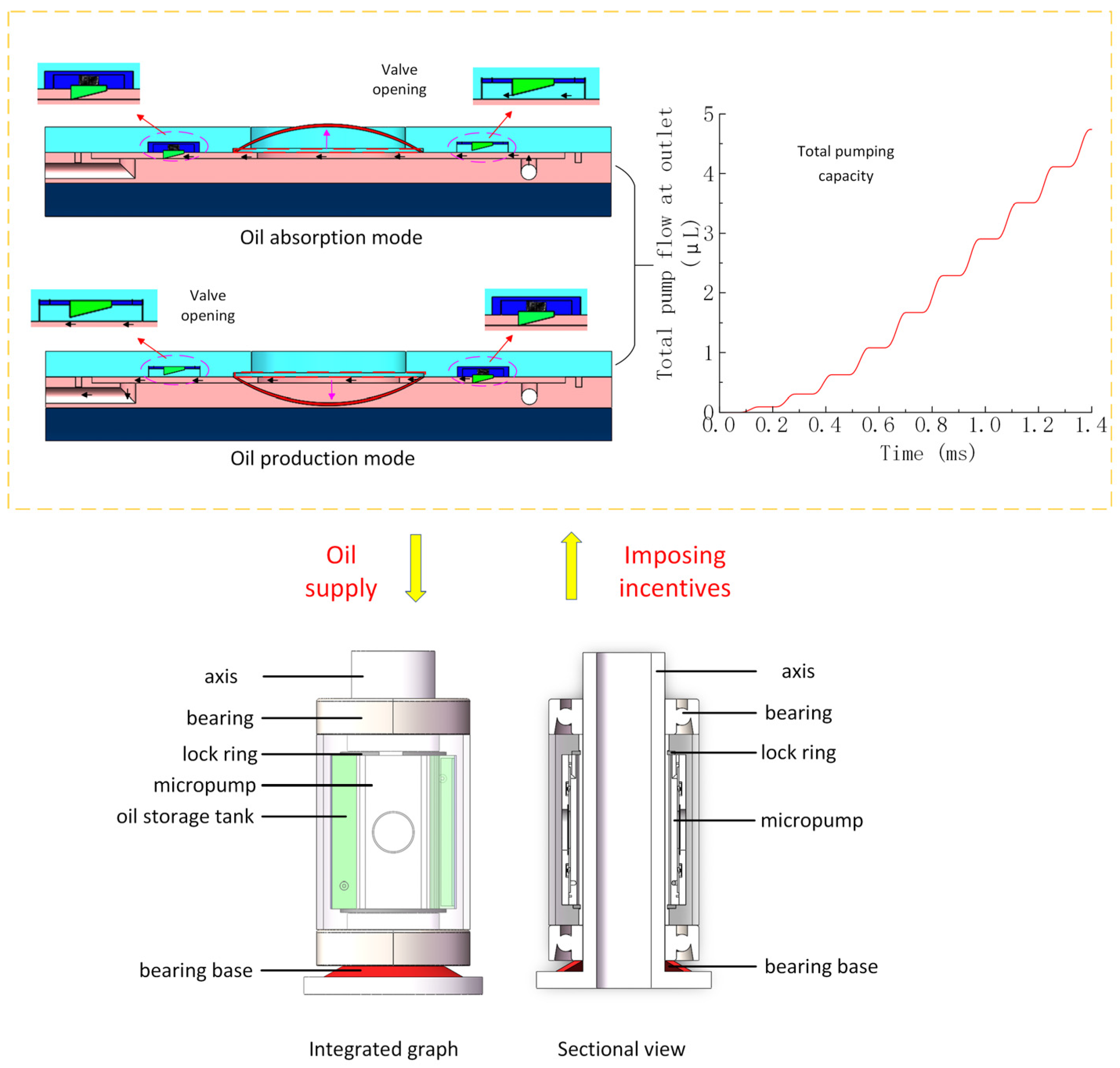
The active lubrication principle diagram is shown in Figure 2. When periodic square wave signals are introduced at both ends of the oscillator, the oscillator vibrates and deforms. At the same time, the oil begins to periodically eject from the outlet. When the oscillator is convexly deformed upward, the inlet valve opens and the outlet valve closes. The lubricating oil enters the cavity from the oil inlet hole, and the cavity expands. Then, a pulsating negative pressure is generated in the cavity. Under the double action of negative pressure and kinetic energy, the droplets are separated from the fluid in the cavity, and then fly out to form droplets. When the vibrator deforms downward, the inlet valve closes and the outlet valve opens. The oil is compressed, and the instantaneous pulsating high pressure is generated in the cavity. High pressure drives the droplets to converge at the outlet and obtain kinetic energy. From the above analysis, it can be seen that the oil is periodically and uniformly ejected with the periodic deformation of the piezoelectric vibrator, so as to achieve the effect of supplying oil to the bearing. The physical photos and size information of the micropump are shown in Figure 3.
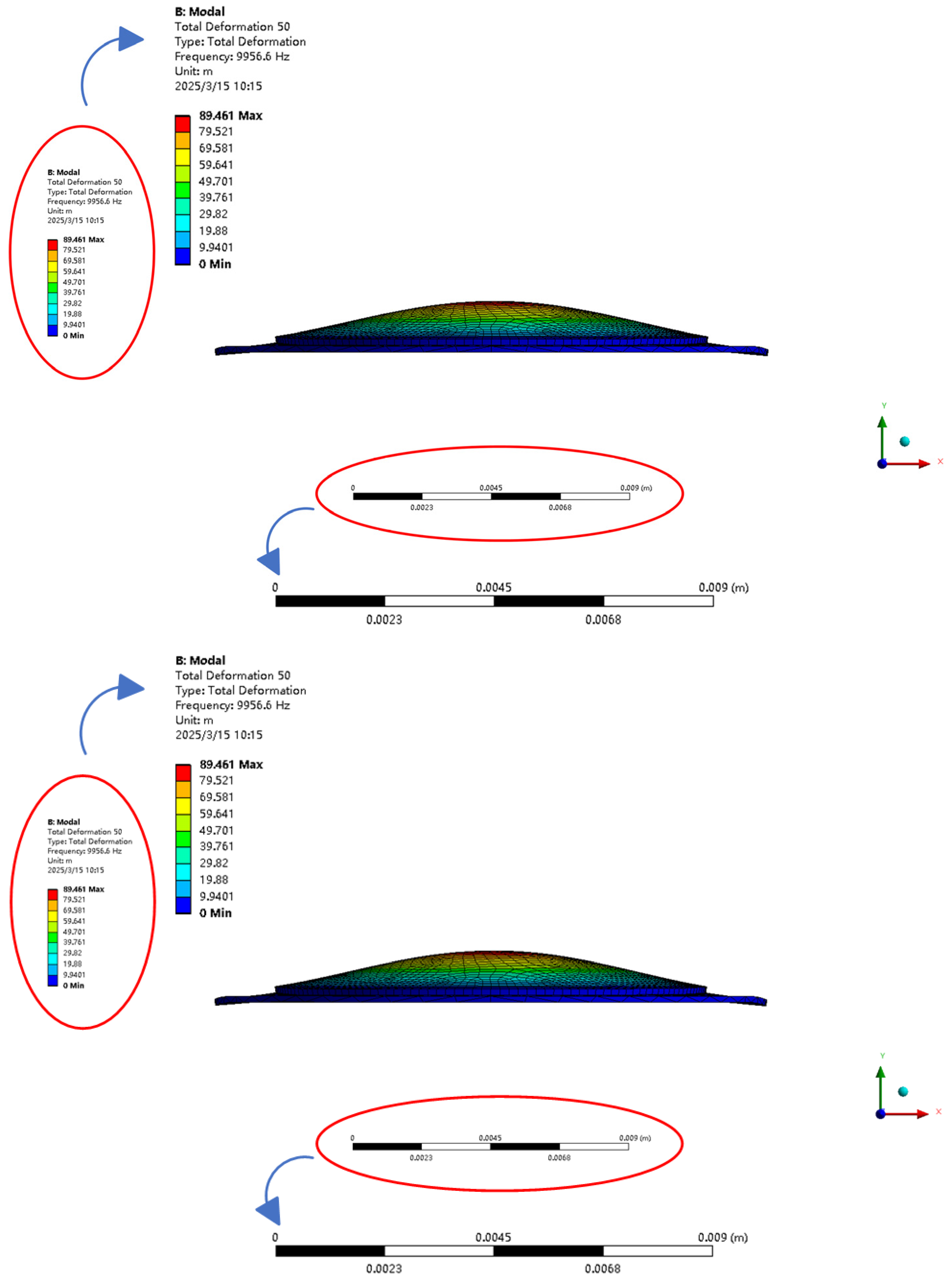
Firstly, the modal analysis of the piezoelectric micropump is carried out. We use the expansion and expansion characteristics of piezoelectric ceramics to drive the pump body to work. In order to optimize the design and efficiency of the micropump, modal simulation analysis can help us understand the dynamic characteristics of the system. In this way, we can improve the performance of the micropump. Modal simulation analysis is mainly to analyze the vibration characteristics of piezoelectric ceramics. Then, we evaluate the natural frequencies, mode shapes, and amplitudes of the system at different operating frequencies. Through modal analysis, we can identify whether resonance may occur under certain working conditions. According to the modal analysis, we can further determine how to optimize the design to meet the resonance conditions in order to achieve better vibration performance. The modal frequency analysis of the piezoelectric micropump is shown in Figure 4. Its natural frequency is 9956 Hz. At this frequency, the micropump can work stably and provide a theoretical basis for the design optimization of the micropump.
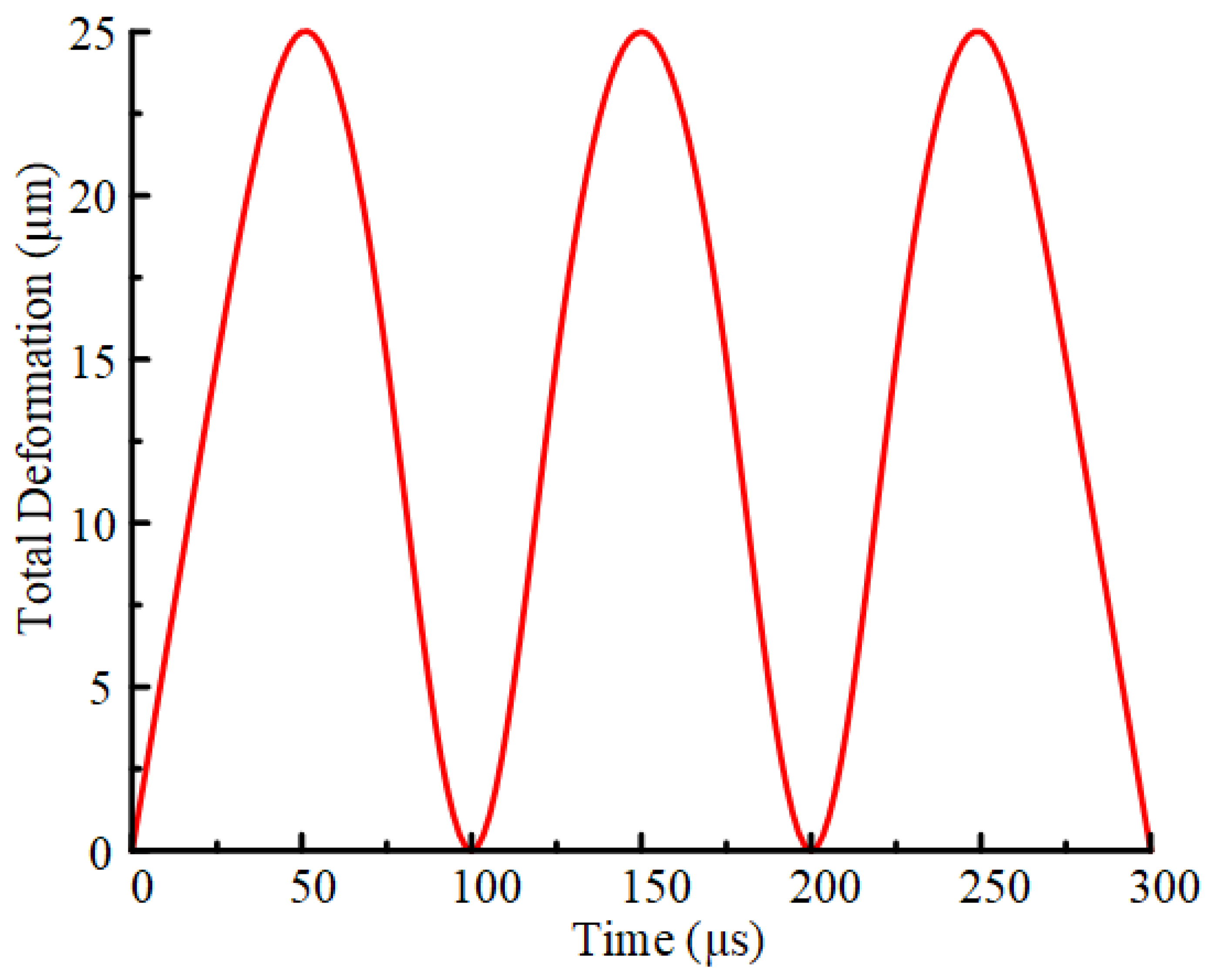
After completing the modal analysis of the piezoelectric micropump, we further perform transient simulation analysis. Through transient simulation analysis, the dynamic response characteristics of the piezoelectric micropump under actual working conditions are studied. Transient analysis can reveal the hydrodynamic behavior of the piezoelectric micropump under different driving signals and the transient performance of the system. Transient analysis is mainly to study the fluid transport characteristics of the piezoelectric micropump under transient conditions. We obtain the influence on the transient performance of the micropump by applying an excitation signal to the piezoelectric ceramic. According to the results of modal analysis, 9.95 kHZ is selected as the working frequency. As shown in Figure 5, the shape of the piezoelectric vibrator changes periodically, increasing first and then decreasing. We believe that the reason for this phenomenon is that a stable excitation signal is applied to the piezoelectric ceramic. The highest point represents the maximum deformation of the piezoelectric vibrator, and the lowest point represents the piezoelectric vibrator returning to the initial position. By applying an excitation signal to the piezoelectric ceramic, the piezoelectric vibrator can achieve stable periodic deformation. The transient simulation analysis provides an important reference for the design and optimization of piezoelectric micropumps. By reasonably designing the piezoelectric driving signal and valve structure, the performance and reliability of the micropump can be significantly improved.
In order to further reveal the principle of the piezoelectric micropump and study the influence of frequency, voltage, and oil viscosity on the operation of the micropump, the fluid–solid coupling analysis of the designed piezoelectric micropump device is carried out. Different from the device structure diagram, the watershed meshing model is shown in Figure 6. It can be seen from Figure 6 that in order to simulate the injection of oil from the nozzle into the air, we added a fluid domain in the cavity to simulate the external air environment. We set the piezoelectric vibrator as the domain and the cavity part as the fluid domain (oil). We choose PZT-5H as the material of PZT ceramics. Its Young’s modulus is 56 GPa, Poisson’s ratio is 0.36, and density is 7600 kg/m3. The following are the reasons why we chose PZT-5H. Considering the piezoelectric constant, the piezoelectric ceramic working mode of our piezoelectric micropump is D31 mode. The D31 mode focuses on the d31 constant. According to the relevant ceramic standards of IEEE, the d31 of PZT-5H is relatively large. Therefore, we mainly choose PZT-5 H. The copper sheet is made of copper with a Young’s modulus of 108 GPa, a Poisson’s ratio of 0.32, and a thickness of 0.2 mm. We use the transient structure analysis module and fluent module to simulate the fluid–solid coupling analysis.
In the transient analysis module, we apply the fixed boundary conditions to the bottom of the micropump, and set the surface of the piezoelectric vibrator in contact with the fluid domain as a fluid–solid interface. We apply a square wave pulse signal to the piezoelectric vibrator. In the fluent module, the fluid domain is meshed. We use the dynamic mesh method (remeshing and smoothing) to simulate the dynamic change of the fluid domain caused by the deformation of the piezoelectric vibrator through the coupled surface. The inlet of the fluid domain is set to a pressure inlet of 0 MPa constant pressure, and the outlet of the fluid domain is set to a pressure outlet of 0 MPa constant pressure.
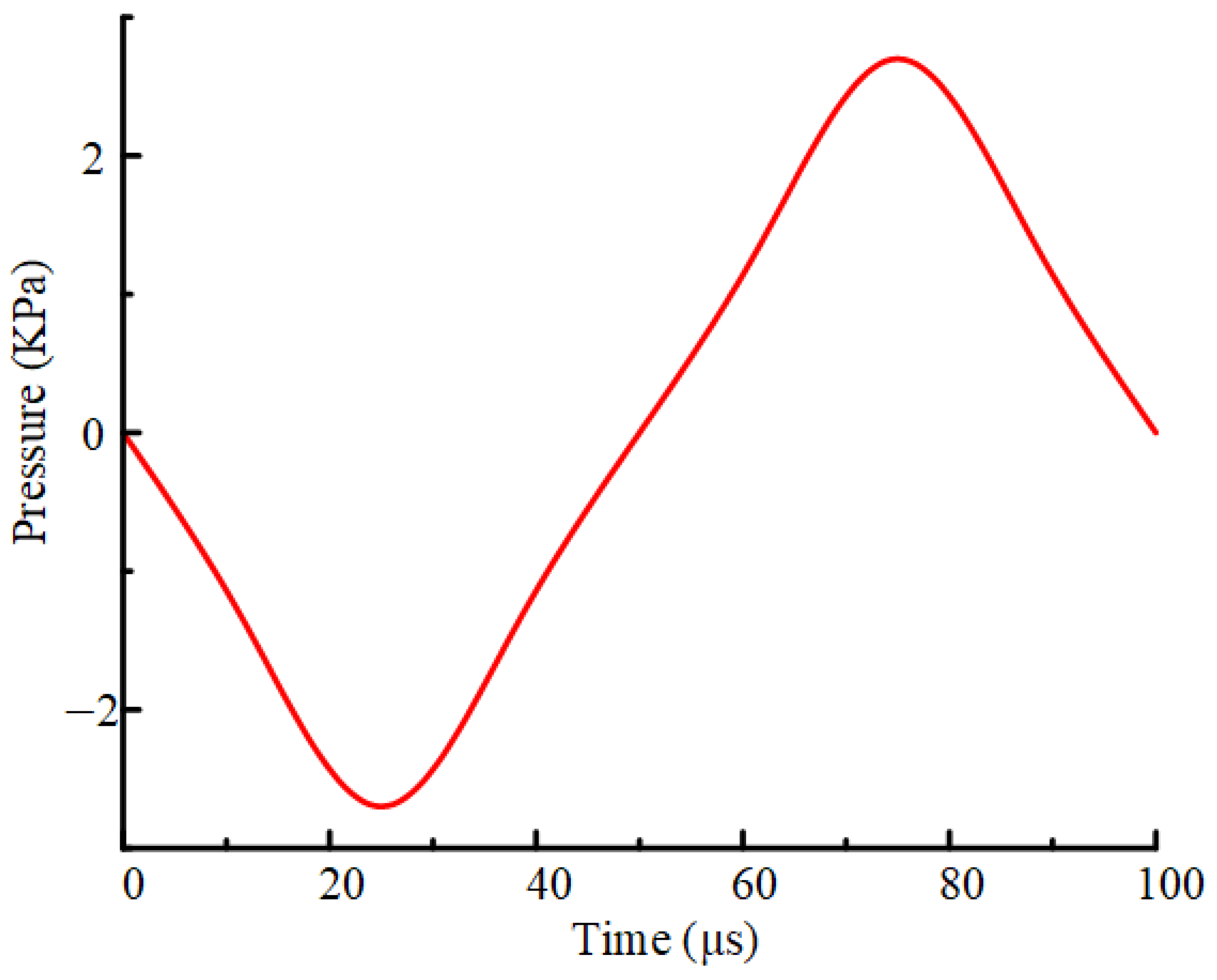
The cavity pressure diagram of the piezoelectric micropump device under standard parameters is shown in Figure 7. At the initial time, the pressure is 0. When the excitation signal is applied to the piezoelectric ceramic, the piezoelectric vibrator begins to vibrate. When the chamber reaches a certain pressure, the inlet valve is opened and the lubricating oil is pumped into the chamber. Then, the liquid in the cavity increases and the pressure increases, reaching the highest point of the curve in Figure 6. When the cavity is filled with lubricating oil, the inlet valve is closed and the outlet valve is opened. The lubricating oil is pumped out of the cavity, the liquid in the cavity is reduced, and the pressure is reduced.
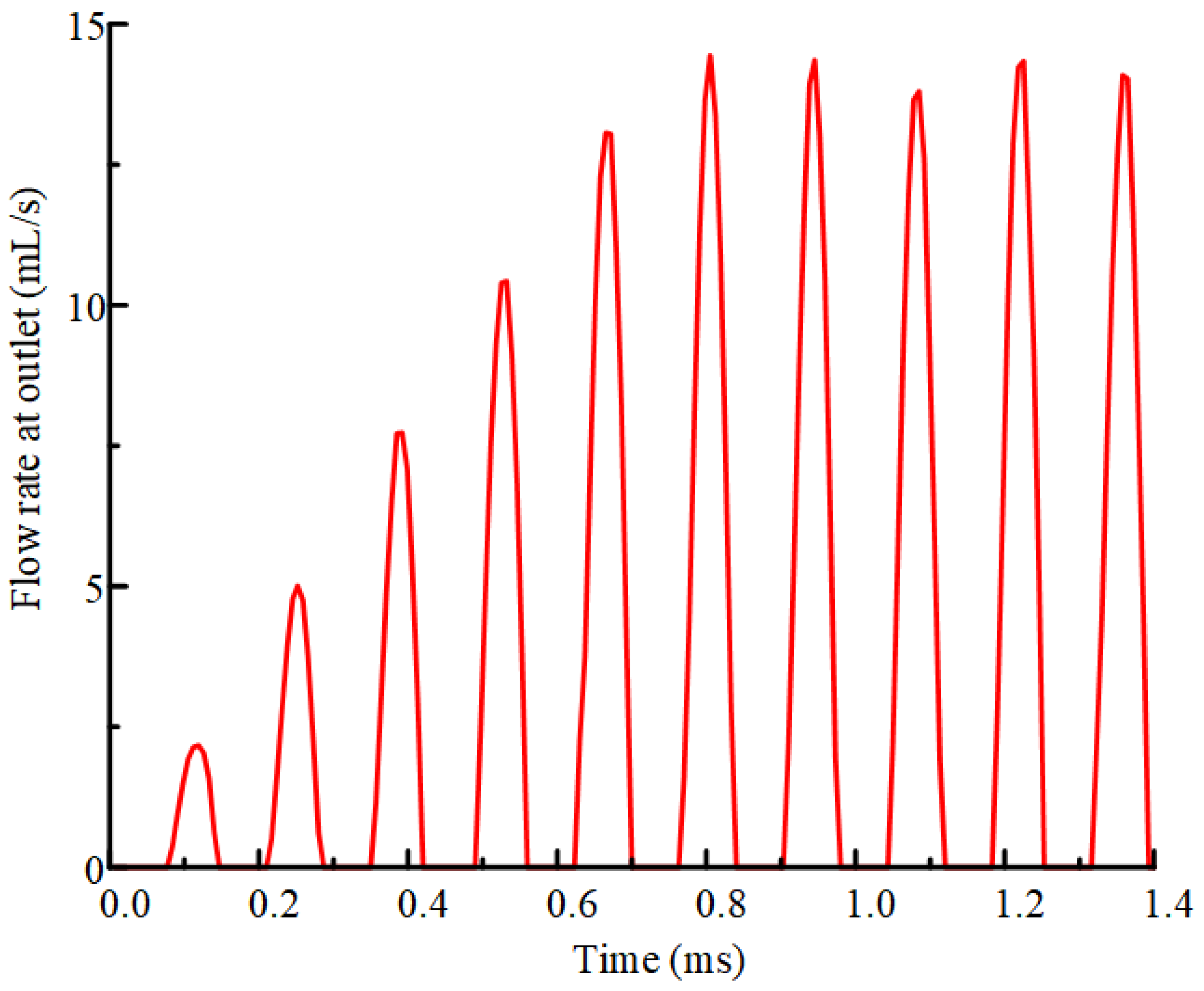
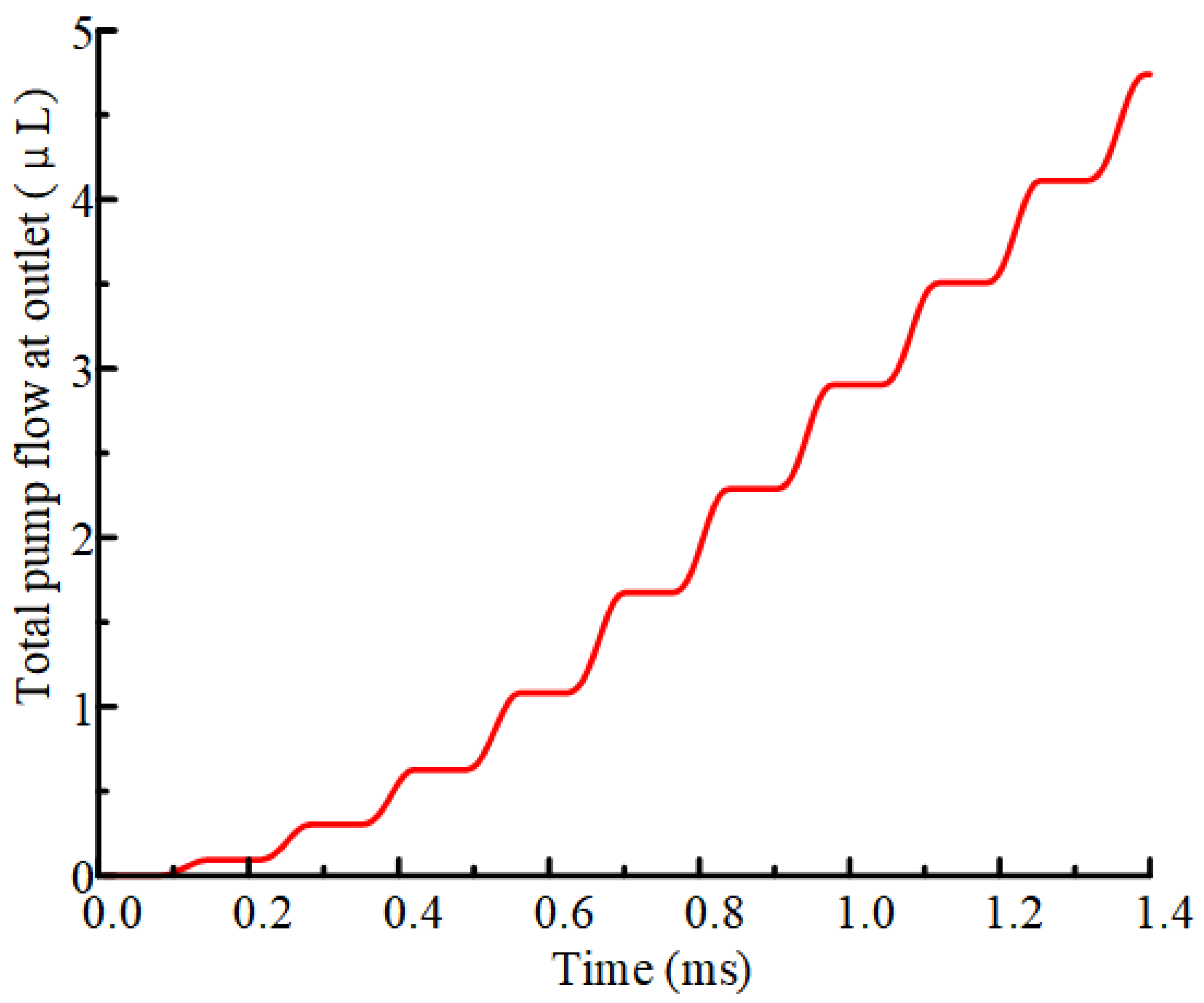
After that, we conducted a coupling analysis of the pumping characteristics of the pump. Then, we get the result of the change of the flow at the outlet with time, as shown in Figure 8. With the change of time, the pumping volume at the outlet increases gradually, and then changes periodically. The highest point of the curve represents the maximum pumping capacity, and the lowest point represents that there is no oil pumping out at this moment. When the cavity is filled with oil, the cavity will pump out oil, and the pumping capacity will also increase. The total pumping capacity at the outlet is obtained by integrating the flow rate. As shown in Figure 9, the total pumping capacity increases with time. When the pressure in the cavity is the largest, that is, when it is filled with lubricating oil, the pumping capacity is stable. After pumping out the lubricating oil in the cavity, the pump oil volume increases and changes periodically.

3. Performance Controlling

This part mainly studies the pumping performance of micropump. When the micropump is under different voltage, frequency, and oil viscosity conditions, we analyze the variation of the pumping volume and output pressure of the micropump. We use pumping volume to reflect pumping performance. For micropumps, what we should really look at is the flow rate, but our innovation is for the active lubrication of bearings. Lubrication is more concerned about the amount of lubricating oil. So, we use the pumping volume to reflect the pumping performance. By systematically testing the effects of different voltages, frequencies, and oil viscosities on the performance of the micropump, we evaluated its output capacity and stability under various working conditions. These studies help us to optimize the design and operation parameters of the micropumps, thereby improving their efficiency and reliability in various applications.
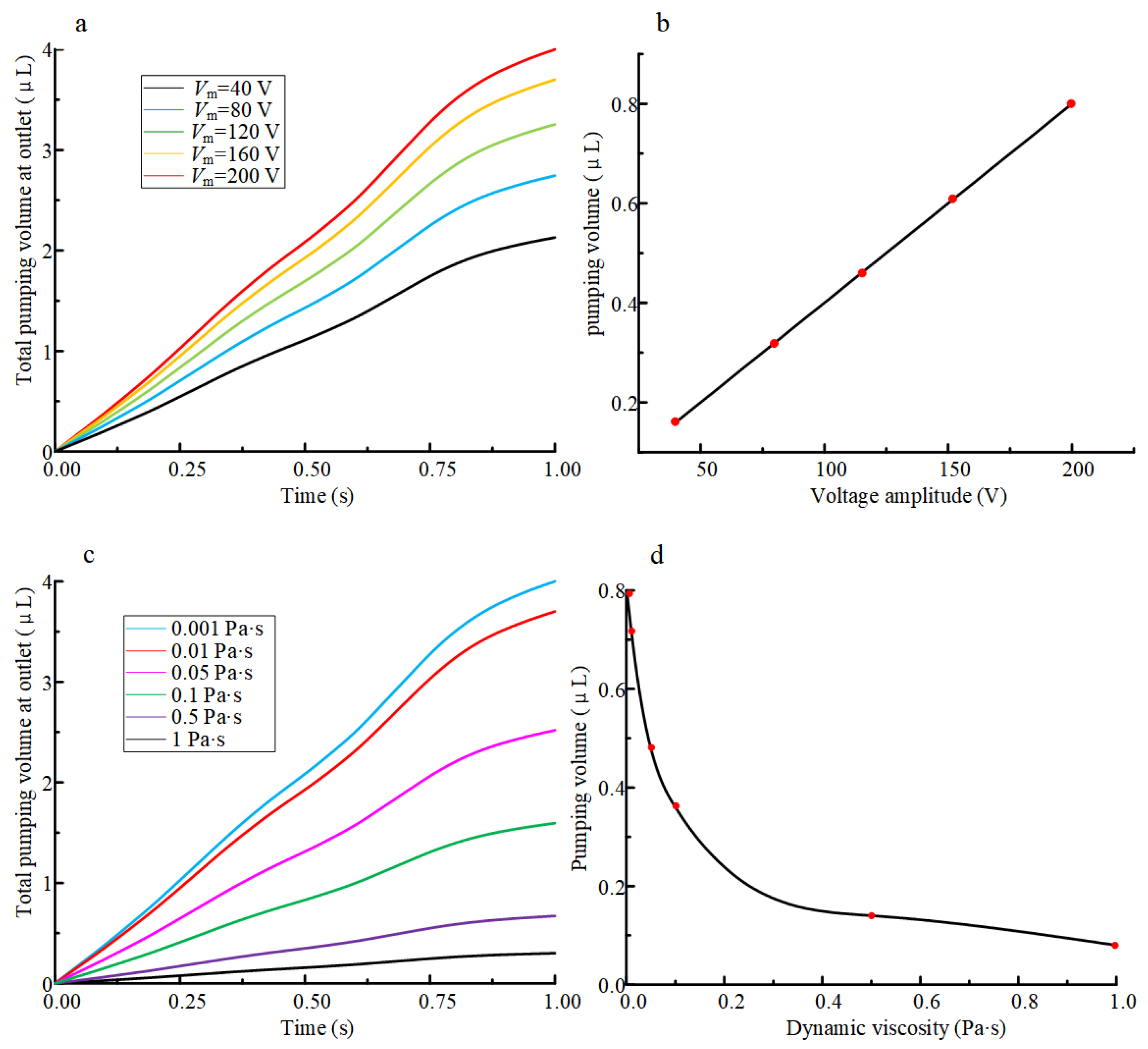
In the case of a certain structural size, the characteristics of the piezoelectric micropump are mainly achieved by adjusting the excitation. The piezoelectric micropump designed in this paper is mainly used for the accurate transportation of fluid. The piezoelectric actuator works in a non-resonant state, and the external excitation is a sinusoidal periodic voltage. Therefore, this part mainly studies the influence of voltage amplitude on pumping performance. At the oil viscosity of 0.001 Pa·s, when the piezoelectric micropump is subjected to periodic voltages with different voltage amplitudes, the total pumping volume results are presented in Figure 10a. Vm represents the inter-peak voltage. It can be seen that with the increase of the voltage amplitude, the curve fluctuation intensity and the total pumping volume gradually increase. At 1 s, the five curves reach the highest point, and the maximum pumping capacity is larger than that of other voltage amplitudes when the voltage is 200 V. That is to say, we can increase the pumping capacity of the micropump by increasing the applied voltage value.
According to the results of Figure 10b, we get the pumping volume in a cycle. In addition, the pumping capacity increases linearly with the increase of voltage amplitude. When the voltage amplitude is 50 V, it is at the lowest point of the curve, that is, the minimum pumping capacity. When the voltage amplitude is 200 V, the maximum pumping capacity is reached. Therefore, by adjusting the voltage amplitude, we can effectively control the pumping characteristics. By increasing the voltage amplitude, the micropump can obtain a larger pumping capacity.
The pumping characteristics of the micropump are also affected by the viscosity of the pumping fluid. When the voltage is 200 V, and the pumping fluid has different viscosities, the total pumping capacity is shown in Figure 10c. With the increase of time, the pumping capacity increases. At 1 s, when the oil viscosity is 0.001 Pa·s, the pumping capacity of the micropump reaches the maximum value. At the same time, when the oil viscosity is 1 Pa·s, the pumping amount obtained by the micropump is the smallest. For the effect of viscosity on pumping performance, we give a quantitative analysis. The pumping variation per unit viscosity is 0.72 μL/Pa·s. Regarding the effect of temperature on viscosity, we are oriented to active lubrication in small space environment. The temperature is generally kept between 20° and 30°. So, we do not need to consider the effect of temperature on oil viscosity. So, we can increase the pumping capacity by reducing the oil viscosity. The results of the pumping volume of a cycle varying with different viscosities are shown in Figure 10d. When the oil viscosity is 0.001 Pa·s, the pumping capacity in a cycle reaches about 0.8 μL. When the oil viscosity is 1 Pa·s, the pumping capacity reaches the minimum value. We can see that the pumping capacity decreases with the increase of viscosity.

4. Experiments

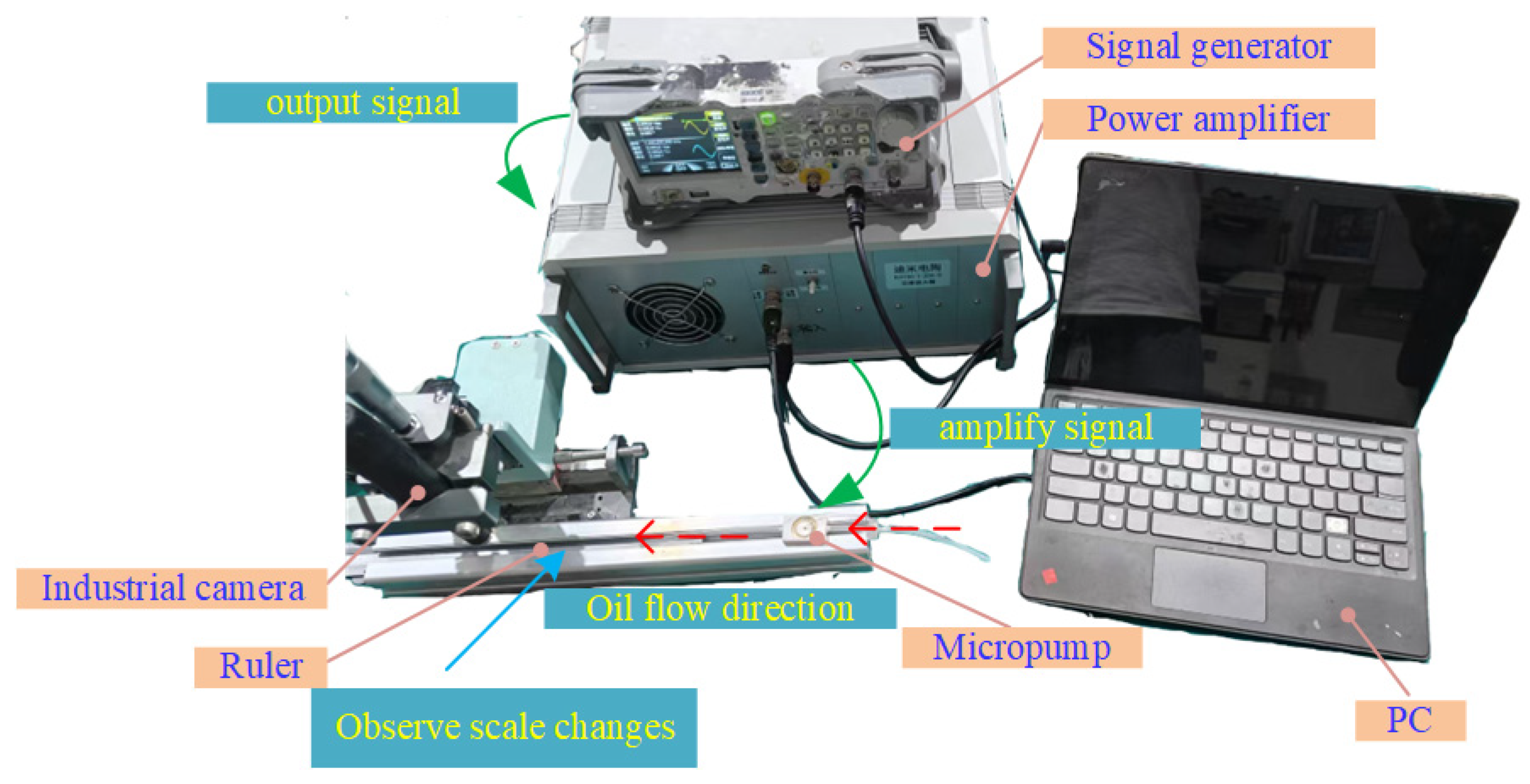
In order to verify the results, we fabricated a prototype based on the designed piezoelectric micropump. We conducted experiments, and the experimental platform system is shown in Figure 11.
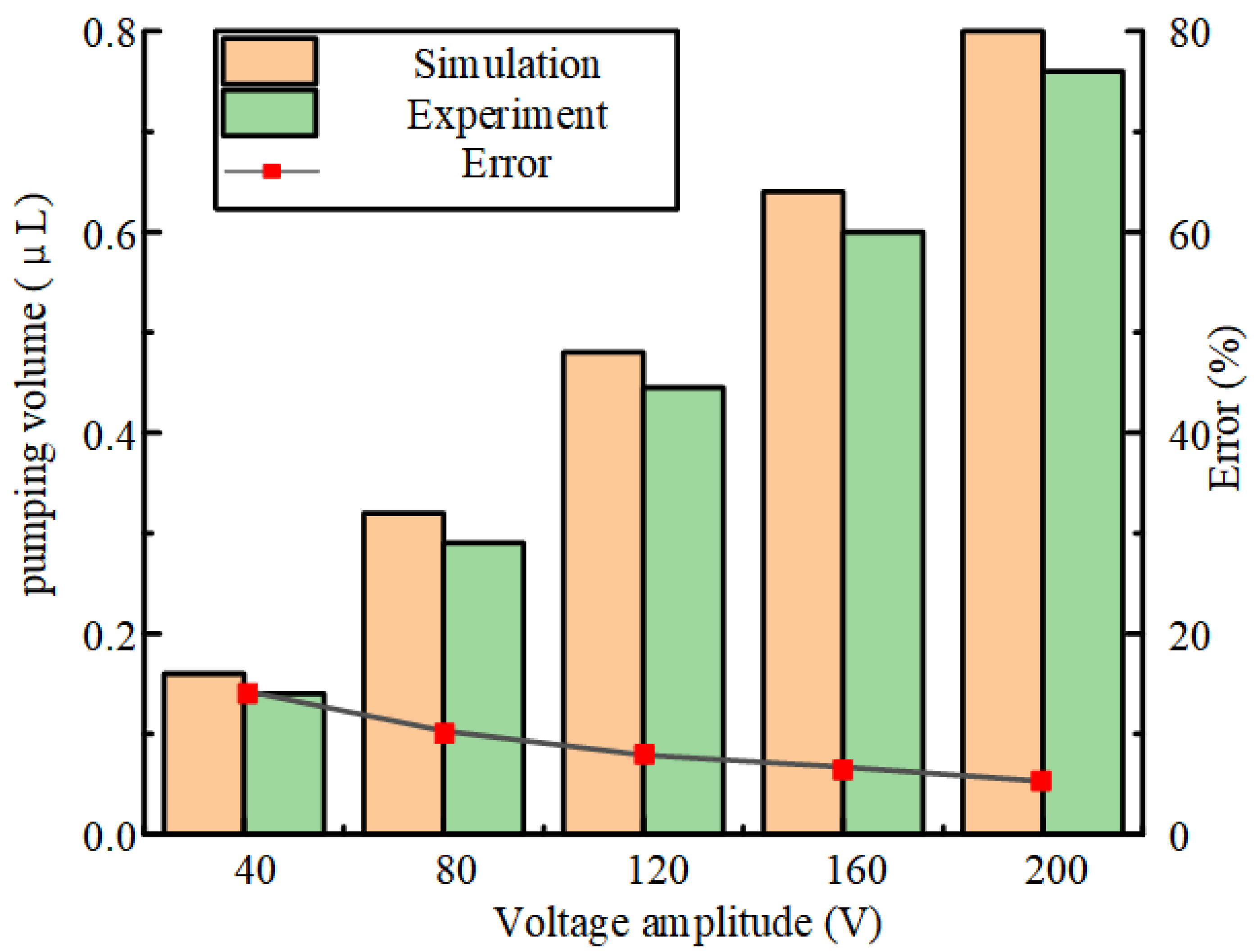
When the viscosity of the oil is 0.001 Pa·s, we apply different amplitudes of periodic voltage to the piezoelectric micropump with valve. The results of the pump volume in one cycle are shown in Figure 12. As the voltage increases, the pumping capacity also increases. When the voltage is 200 V, both the theoretical pumping capacity and the experimental pumping capacity reach the maximum. When the voltage is 40, the theoretical pumping capacity and the experimental pumping capacity reach the minimum value. When the voltage is 40 V, the error reaches the maximum value. In Figure 12, when the voltage is below 200 V, the error between the experimental data and the theoretical data becomes smaller and smaller as the voltage increases. We believe that the reason for this phenomenon is that the amplitude of the piezoelectric vibrator is small at low voltage. It causes the valve to open and close with an insufficient driving force. The valve may not be fully opened, so this leads to a delay in opening and closing the valve. As the voltage increases, the amplitude increases. As the amplitude increases, the driving force increases. The opening and closing speed of the valve becomes faster. Then, this phenomenon reduces the error. When the voltage is 200 V, the error reaches the minimum value. When the voltage is increased, the error between the experimental data and the theoretical data is smaller and smaller. The experimental results are the same as the simulation results, and the error is within the acceptable range. We can reduce the error value by increasing the voltage.
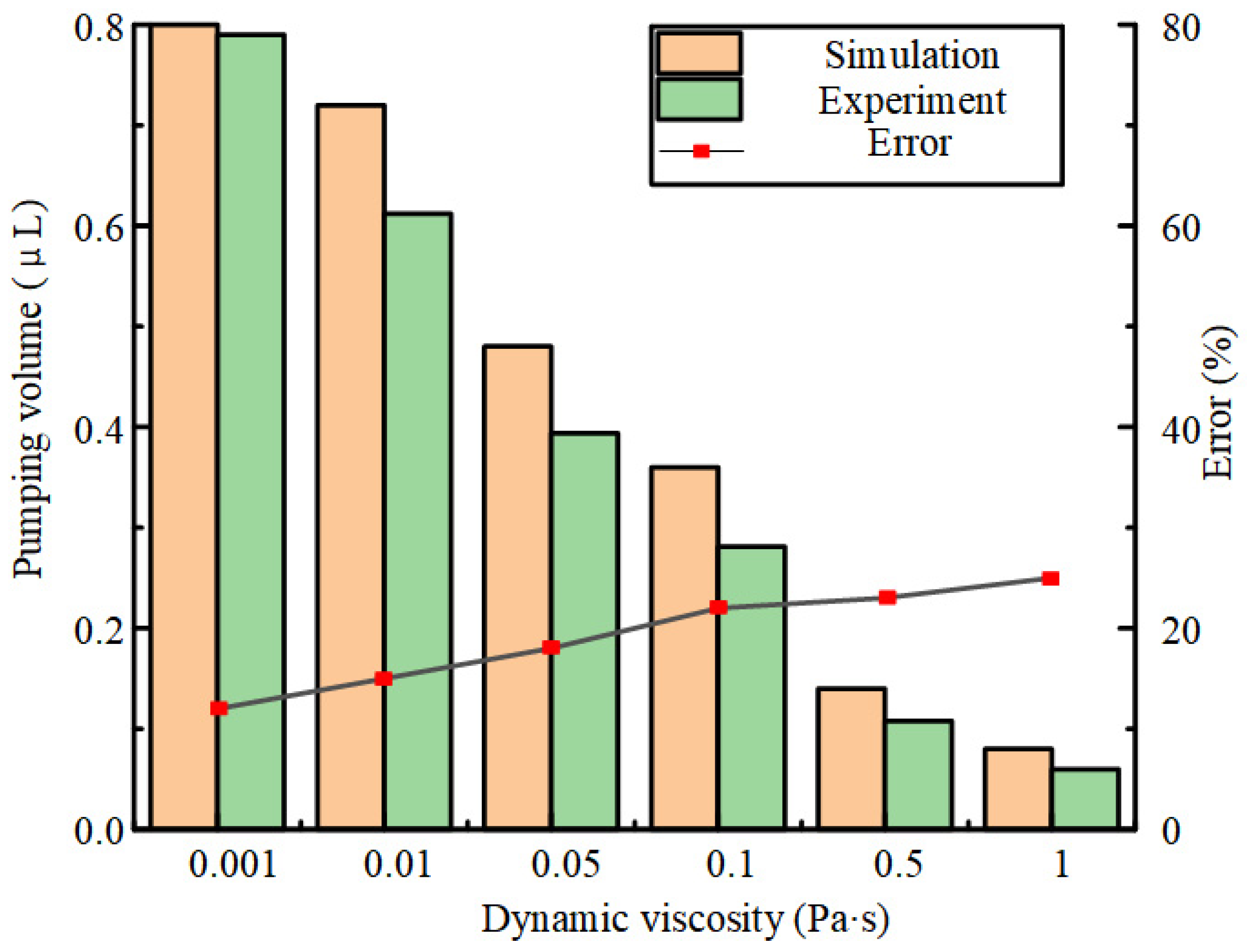
At a voltage of 200 V, when pumping fluids of different viscosities with a valved piezoelectric micropump, the results of the pump volume in a cycle are shown in Figure 13. When the oil viscosity is 0.001 Pa·s, the theoretical pumping capacity and the experimental pumping capacity reach the maximum, and the error is the smallest. When the oil viscosity is 1 Pa·s, the theoretical pumping capacity and the experimental pumping capacity reach the minimum value, and the error is the largest. We believe that the increase of oil viscosity affects the pumping performance. With the increase of oil viscosity, the pumping capacity decreases, but the error will increase with the increase of oil viscosity.
We can get a conclusion from Figure 12 and Figure 13. When the micropump frequency is 9.95 kHz, the voltage is 200 V, the oil viscosity is 0.001 Pa·s, and the pumping capacity can reach 0.8 μL. When the same excitation signal is used, the experimental pumping capacity reaches 0.76 μL. The theoretical and experimental error is 5.3%. In this paper, the reasons for the error between the experimental pumping volume and the theoretical pumping volume are described from the following aspects. From the point of view of model simplification, we assume that the valve plate is a massless rigid body under ideal conditions. The opening and closing of the valve is completed in an instant. In fact, the valve plate has mass and moment of inertia. When the driving frequency is high, the valve plate will change slower than the fluid pressure because of the inertia. It causes the valve opening time to be slower than the theoretical value. It also leads to a certain error in the pumping volume. In terms of material properties, the elastic coefficient of the spring will change with temperature. It leads to a certain error in the experimental pumping volume. Under high frequency vibration, the amplitude of the piezoelectric vibrator will also decrease due to the dielectric loss. Thus, the pumping capacity has a certain impact. In terms of experimental noise, the driving voltage output by the signal generator may contain other harmonics. These harmonics cause the actual vibration frequency of the piezoelectric vibrator to deviate from the theoretical value.
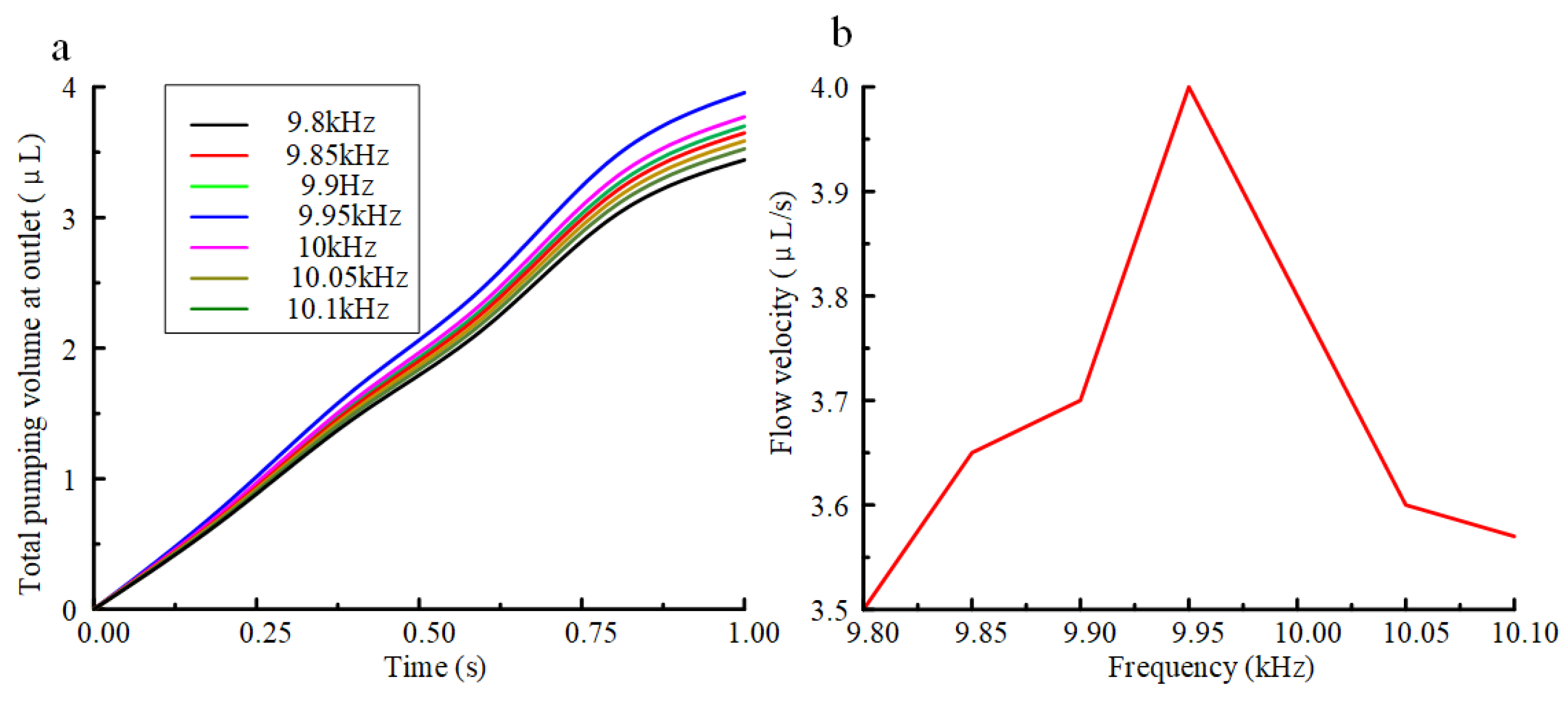
The signal frequency also affects the pumping performance. When the applied signal frequency is exactly at the frequency of a certain order mode of the oscillator, the amplitude of the oscillator will increase. We affect the pumping performance by changing the vibration amplitude of the vibrator. The influence of the frequency change of the signal on the pumping performance is shown in Figure 14a. With the change of time, the pumping capacity at each frequency increases. When 9.95 kHz is applied, the pumping capacity is greater than when other frequencies are applied. We can see that in the range of 9.8 kHz to 10.1 kHz, the frequency has a great influence on the pumping performance. The flow rate of lubricating oil at different frequencies is shown in Figure 14b. In the process of 9.8 kHz to 9.95 kHz, the flow rate of lubricating oil increases continuously. In the process of 9.95 kHz to 10.1 kHz, the flow rate of lubricating oil decreases continuously. At 1 s, when the frequency is 9.95 kHz, the pumping capacity reaches the maximum value. Therefore, we can increase the pumping capacity by adjusting the frequency to about 9.95 kHz.

5. Lubrication Performance

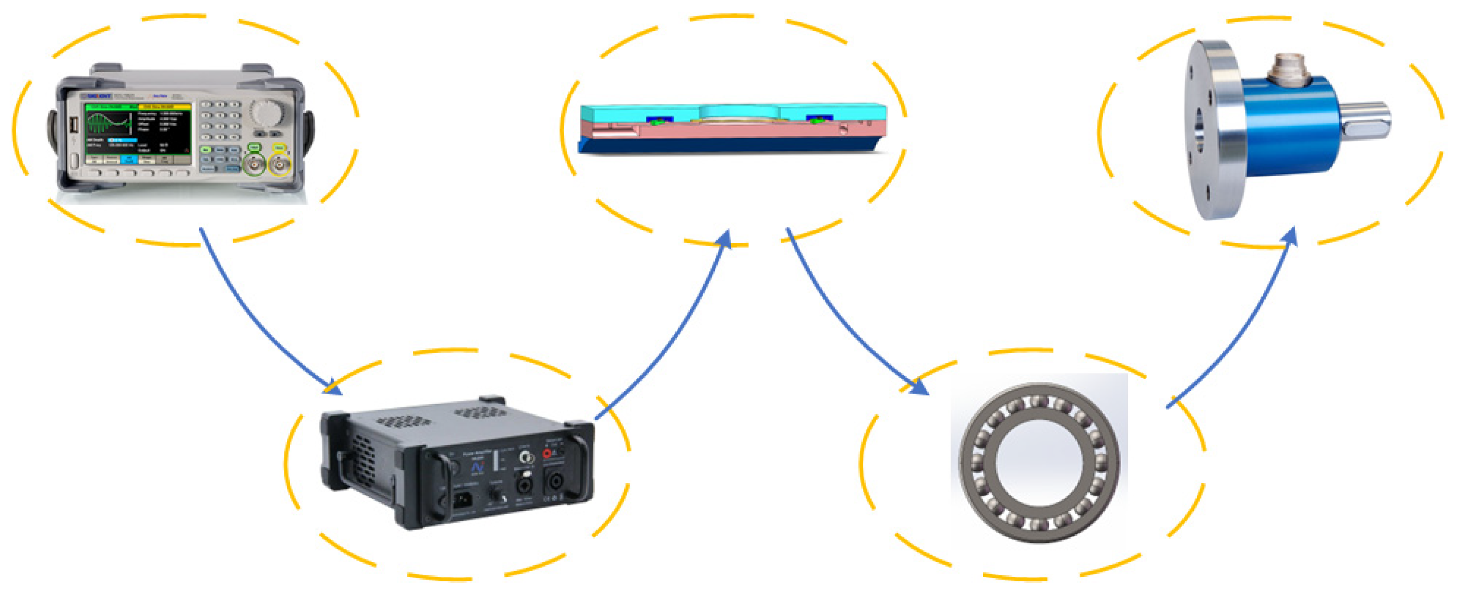
In this part, we will carry out the calculation of oil demand and the measurement of bearing friction torque. The flow chart of the experiment is shown in Figure 15. First, we use a signal generator to transmit the signal to the power amplifier. The power amplifier amplifies the voltage and then applies it to the piezoelectric micropump. Then, the piezoelectric micropump starts to work under the action of excitation. After the lubricating oil is conveyed to the bearing, we use a torque sensor to measure the friction torque of the bearing.
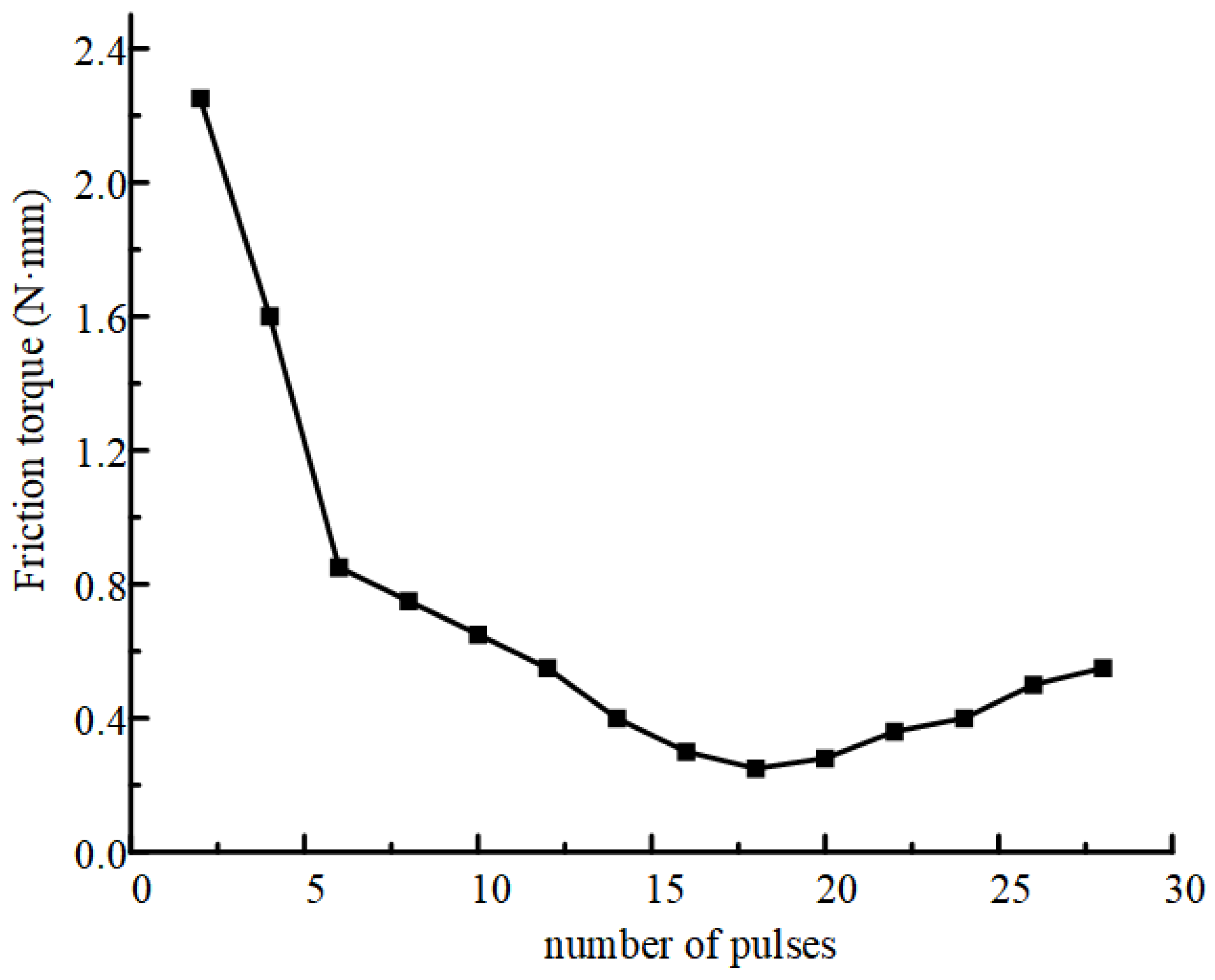
When we gradually apply the voltage pulse, the change process of the bearing friction torque is shown in Figure 16. It can be seen that with the increase of the number of applied voltage pulses, the friction torque of the bearing gradually decreases in the early stage. Moreover, when 18 voltage pulses are applied, the friction torque reaches its minimum value. Then, when more voltage pulses are applied, the friction torque increases. Before applying 18 pulse signals, as the pulse signal increases, the lubricant gradually fills the cavity. Then, the lubricating oil film is formed in the cavity. Lubrication oil changes from friction state to fluid lubrication. Therefore, the bearing friction torque is significantly reduced at this stage. At the same time, when 18 pulse signals are applied, the oil film thickness reaches the critical value. The friction torque reaches the minimum value. After applying 18 pulse signals, adding more lubricating oil will cause too much lubricating oil in the oil film. Too much lubricating oil leads to the increase of viscosity resistance of the lubricating oil. The increase of viscosity resistance of the lubricating oil leads to the increase of friction torque. Therefore, we can adjust the friction torque of the bearing by adjusting the number of applied voltage pulses. Therefore, under this condition, the number of voltage pulses required to achieve micro-redundancy lubrication is 18, and the amount of micro-redundancy lubrication is about 0.93086 μL. We also understand this trend from the relevant literature [12]. The relevant literature also increases the validity of the experimental results.
The amount of micro-excess lubricating oil is based on the theory of central oil film thickness. The central oil film thickness hc of deep groove ball bearings operating under elastohydrodynamic lubrication can be calculated by Formula (1). Formula (1) was derived by Hamrock and Dowson in Ref. [35]. U, G, W, and k are parameters related to speed, material, load, and ovality, respectively. The equivalent radius R is calculated according to R = 1/K, where K is the curvature sum of the ball and the raceway, and e is the natural logarithm. We consider the applicability of this formula in our work. This formula is valid under our experimental conditions. Our oil demand volume is calculated by the formula. At the same time, we also measured the oil demand of the experiment, but there will be some errors. Temperature has no effect because the temperature is almost constant during the pumping process. For a geometric shape, we really cannot guarantee that it is an ideal geometric shape. We can not guarantee that the raceway is a perfect rotating body. So, there will be errors. This also explains the phenomenon that there are errors in the theoretical calculation and experiment, but we believe that the error is within a reasonable range.
h c = 2.69 U 0.67 G 0.53 W 0.067 ( 1 0.61 e 0.73 k ) / K
The central oil film thickness can be considered as the average oil film thickness required for the normal operation of deep groove ball bearings. During the rotation process, the lubricating oil is evenly distributed on the inner and outer raceways and balls. Therefore, for deep groove ball bearings with N rollers, the volume of lubricating oil required for micro-redundancy lubrication can be calculated [12] as follows:
V t o t a l h c o S o + h c i S i + N S r ( h c o + h c i ) / 2
In the formula, S represents the effective contact area of the lubricating oil film. The subscripts o, i, and r refer to the inner ring raceway, outer ring raceway, and ball, respectively.
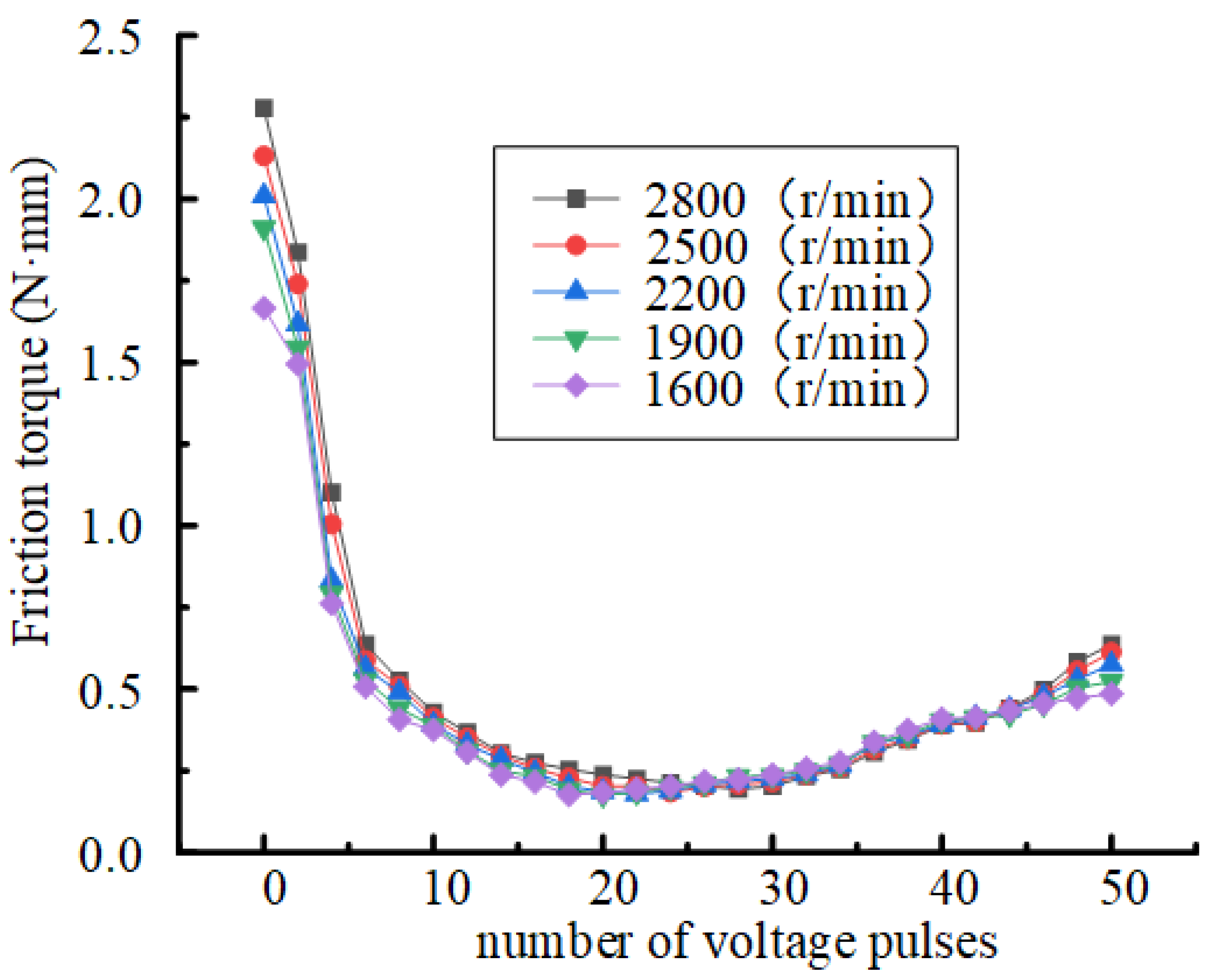
When a voltage pulse with an amplitude of 120 V is applied to the piezoelectric micropump, the test results of the bearing rotating at different speeds are shown in Figure 17. It can be seen that with the increase of rotational speed, the number of voltage pulses required to achieve micro-redundancy lubrication increases, that is, the total amount of lubricating oil required to increase. Micro-redundancy is a state that is difficult to achieve exactly satisfied. Our system is ultimately based on the current of the motor to feedback the change of friction torque. This process forms a closed-loop control. With the increase of lubricating oil, the friction torque is smaller and smaller, but it is difficult to get the best point through feedback. For example, when we apply 18 pulse signals, the friction torque increases only when there is a small amount of redundancy. It shows that the lubrication is just past the critical state. This is the explanation of micro-redundancy lubrication. The minimum friction torque of the bearing increases with the increase of the rotational speed. When we apply 18 pulse signals, the bearing friction torque reaches the minimum value. We observe the moment when 18 pulse signals are applied. With the increase of rotational speed, the friction torque of the bearing increases. That is, the minimum friction torque of the bearing increases with the increase of the rotational speed. Here, we only test the results of bearings rotating at relatively low speeds. We aim to ensure that the designed micro-jets can achieve micro-redundant lubrication when a small amount of total oil is required.
In fact, we are concerned about how many voltage pulses should be applied to achieve micro-redundancy lubrication. In order to predict the required number of voltage pulses, we should first calculate the total amount of oil required for the bearing to operate under different conditions. Then, the droplet volume is obtained by coupling analysis. We divide the calculated total volume by the volume of a single droplet to obtain the required number of pulses Ntotal. The calculation model is shown in (3).
N t o t a l = V t o t a l / V s i n g l e
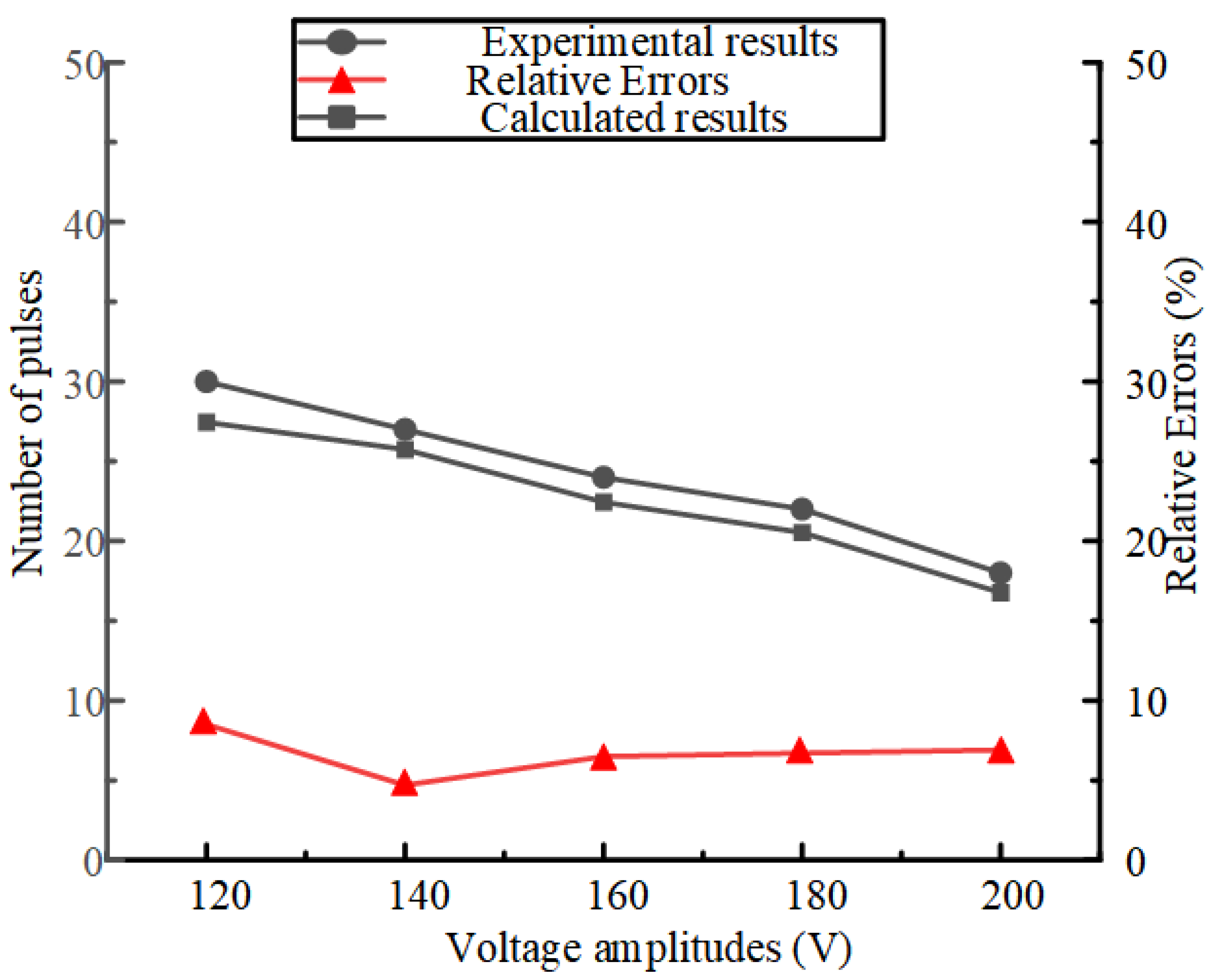
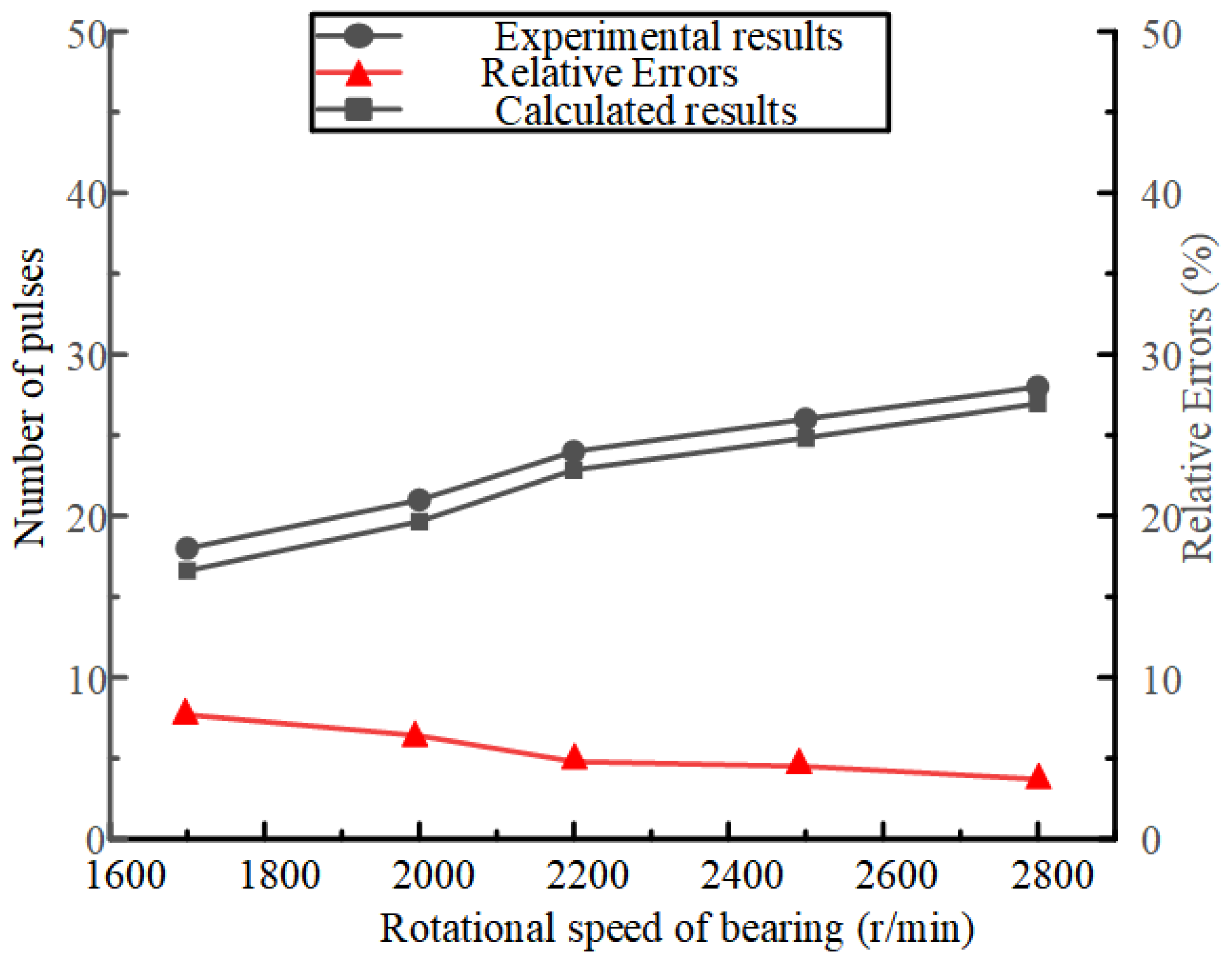
Vtotal is the total volume of lubricating oil required for micro-redundancy lubrication. When the microjet is applied with different amplitude pulse voltages and the bearing rotates at a speed of 2800 r/min, the number of voltage pulses required for micro-redundancy lubrication is obtained by experiment and calculation, as shown in Figure 18. As the voltage increases, the number of pulses required gradually decreases. With the increase of voltage, the amount of injection increases, so the number of pulses decreases. It can be seen from Figure 16 that the number of pulses corresponding to the lowest point of each speed curve represents the number of pulses required for the micro-redundancy lubrication obtained by the experiment. Therefore, when the microjet is applied with a pulse voltage of 120 V, the number of pulses required for bearings at different speeds is shown in Figure 19. With the increase of rotational speed, the number of pulses increases gradually. We believe that the reason is that as the speed increases, the required oil film thickness becomes thicker, so the demand becomes larger. In Figure 19, the error decreases with the increase of bearing speed. We believe that the reason for this phenomenon is that as the bearing speed increases, the oil demand of the bearing will also increase. Then, in this process, our lubrication accuracy is constant. That is, the single injection volume is constant. So, when the amount of oil required increases, the number of jet pulses will increase. When the number of pulses increases, the error between the theoretical value and the experimental value becomes smaller and smaller. So, the error will decrease with the increase of bearing speed. It can be seen that the required number calculated by Formula (1) is consistent with the experimental results. The results prove the effectiveness of the redundant model.
It can be seen from Figure 18 and Figure 19 that the calculated number of pulses is smaller than the experimental results. A slight increase in the number of pulses is acceptable. The error decreases with the increase of bearing speed. The error is kept within 10%, and the relative error is acceptable. In order to reduce the error, we need to adopt the following methods. The errors of Figure 18 and Figure 19 are less than 10%, but the error has no obvious regularity. Therefore, it is not suitable to use a correction factor to deal with the error. We can use a real-time feedback mechanism. Because the real-time feedback mechanism is not subject to regular restrictions, and it fits our current situation, we can use a real-time feedback mechanism to deal with the error.

6. Conclusions

A piezoelectric micropump system based on a moving valve is studied and designed in this paper. Through theoretical analysis and simulation analysis, we verify the effectiveness of the moving valve structure in the piezoelectric micropump. That is, under the simulation analysis, when the applied frequency is 9.95 kHz, the voltage is 200 V, the oil viscosity is 0.001 Pa·s, and the pumping volume can reach 0.8 μL. When the same excitation signal is used, the experimental pumping capacity reaches 0.76 μL, and the theoretical and experimental error is 5.3%. The error is within the acceptable range.
We analyzed the effects of voltage, oil viscosity, and frequency on pumping characteristics. Then, we get the law of pumping performance using different excitation signals. We propose a control method for different properties of lubricating oil. For different viscosities of lubricating oil, you can choose to increase the voltage to increase the amount of pumping in a cycle. At the same time, it is found that in a certain range, the change of frequency has a great influence on the pumping performance. We studied the friction torque and oil demand of the bearing. It can be seen from the experiment that with the increase of the number of applied voltage pulses, the friction torque of the bearing gradually decreases in the early stage. When the number of voltage pulses reaches 18, the friction torque of the bearing reaches a minimum of 0.25 N·mm, and the oil requirement reaches 0.93086 μL. When the number of voltage pulses is increased, the friction torque increases. We have verified by experiments that the calculation formula of oil demand is correct. Therefore, on-demand lubrication can be achieved.

Author Contributions

Conceptualization: Z.Z. and Y.Z.; methodology: Y.W. and X.S.; software and validation: L.L.; formal analysis: Z.Z. and Y.Z.; investigation: Y.W.; resources: L.L.; data curation: Y.Z.; writing—original draft preparation: Z.Z.; writing—review and editing: Y.Z. and X.S.; visualization: Y.W.; supervision: Y.Z.; project administration: K.L.; funding acquisition: Z.Z. All authors have read and agreed to the published version of the manuscript.

Funding

This work was supported in part by the Henan Key Laboratory of High-performance Bearings, Luo Yang 471039, China (Grant No. ZYSKF202306).

Data Availability Statement

The data presented in this study are available on request from the corresponding author.

Conflicts of Interest

The authors declare that they have no known competing financial interests or personal relationships that could have appeared to influence the work reported in this paper.

References

  1. Krishnan, S.; Hsu, H.-Y.; Lee, S.-H.; Gopinath, K. A Bearing Cartridge Assembly for Long-term Performance of Momentum/Reaction Wheels used in Spacecraft. Tribol. Ind. 2014, 36, 22–32. [Google Scholar]
  2. Loewenthal, S.H.; Parker, R.J.; Zaretsky, E.V.; Scibbe, H.W. Operating Characteristics of a 0.87 kW-hr Flywheel Energy Storage Module. 1985. Available online: https://ntrs.nasa.gov/citations/19860040126 (accessed on 1 April 2025).
  3. Chen, W.B.; Wang, W.Z.; Liang, H.; Zhu, P.Z. Molecular Dynamics Simulations of Lubricant Outflow in Porous Polyimide Retainers of Bearings. Langmuir 2021, 37, 9162–9169. [Google Scholar] [CrossRef] [PubMed]
  4. Wang, J.; Zhao, H.; Huang, W.; Wang, X. Investigation of Porous Polyimide Lubricant Retainers to Improve the Performance of Rolling Bearings under Conditions of Starved Lubrication. Wear 2017, 380, 52–58. [Google Scholar] [CrossRef]
  5. Lugt, P.M. A Review on Grease Lubrication in Rolling Bearings. Tribol. Lubr. Technol. Rev. 2010, 66, 44. [Google Scholar] [CrossRef]
  6. Marchetti, M.; Jones, W.R.; Pepper, S.V.; Jansen, M.J.; Predmore, R.E. In-situ, on-demand lubrication system for space mechanisms. Tribol. Trans. 2003, 46, 452–459. [Google Scholar] [CrossRef]
  7. Krishnan, S. Long-Term Lubrication Systems for Momentum Wheels Used in Spacecrafts. Tribol. Int. 2003, 43, 259–267. [Google Scholar]
  8. Estupinan, E.; Santos, I. Controllable Lubrication for Main Engine Bearings Using Mechanical and Piezoelectric Actuators. IEEE-ASME Trans. Mechatron. 2012, 17, 279–287. [Google Scholar] [CrossRef]
  9. Sathyan, K.; Hsu, H.Y.; Lee, S.H.; Gopinath, K. Long-term lubrication of momentum wheels used in spacecrafts-An overview. Tribol. Int. 2010, 43, 259–267. [Google Scholar] [CrossRef]
  10. Morosi, S.; Santos, I.F. Active lubrication applied to radial gas journal bearings. Part 1: Modeling. Tribol. Int. 2011, 44, 1949–1958. [Google Scholar] [CrossRef]
  11. Santos, I.F.; Watanabe, F.Y. Lateral dynamics and stability analysis of a gas compressor supported by hybrid and active lubricated multirecess journal bearing. J. Braz. Soc. Mech. Sci. Eng. 2006, 28, 485–495. [Google Scholar] [CrossRef]
  12. Li, K.; Yang, R.; Liu, J.; Chen, W.; Zhang, L.; Liu, Y. A Trace Redundant Lubrication Piezoelectric Micro-jet for Bearing System. IEEE/ASME Trans. Mechatron. 2018, 2018, 2862824. [Google Scholar] [CrossRef]
  13. Wegert, Z.J.; Roberts, A.P.; Challis, V.J. Multi-objective structural optimisation of piezoelectric materials. Int. J. Solids Struct. 2022, 248, 111666. [Google Scholar] [CrossRef]
  14. Zhang, L.; Zheng, H.; Liu, B.; Liang, Q.; Li, K.; Liu, J.; Chen, W. A piezoelectric energy harvester for multi-type environments. Energy 2024, 305, 132218. [Google Scholar] [CrossRef]
  15. Li, K.; Zhou, X.; Liu, Y.; Sun, J.; Tian, X.; Zheng, H.; Zhang, L.; Deng, J.; Liu, J.; Zhao, J.; et al. A 5 cm-Scale Piezoelectric Jetting Agile Underwater Robot. Adv. Intell. Syst. 2023, 5, 2200262. [Google Scholar] [CrossRef]
  16. Zhou, X.; Li, K.; Liu, Y.; Sun, J.; Li, H.; Chen, W. Development of an Anti-Hydropressure Miniature Underwater Robot with Multi-Locomotion Mode Using Piezoelectric Pulsed-Jet Actuator. IEEE Trans. Ind. Electron. 2022, 70, 5044–5054. [Google Scholar] [CrossRef]
  17. Shan, T.-Y.; Wu, X.-S.; Hu, Y.-W.; Lin, X.-D.; Sun, D.-F. Injection of Viscous Micro-Droplet via Nozzle-Driven Piezoelectric Micro-Jet and Its Performance Control Method. Micromachines 2023, 14, 1267. [Google Scholar] [CrossRef]
  18. Duque, M.; Leon-Salguero, E.; Sacristán, J.; Esteve, J.; Murillo, G. Optimization of a Piezoelectric Energy Harvester and Design of a Charge Pump Converter for CMOS-MEMS Monolithic Integration. Sensors 1895, 19, 1895. [Google Scholar] [CrossRef]
  19. Le, S.; Hegab, H. Investigation of a multistage micro gas compressor cascaded in series for increase pressure rise. Sens. Actuator A-Phys. 2017, 256, 66–76. [Google Scholar] [CrossRef]
  20. Gidde, R.R.; Pawar, P.M.; Dhamgaye, V.P. Fully coupled modeling and design of a piezoelectric actuation based valveless micropump for drug delivery application. Microsyst. Technol. 2020, 26, 633–645. [Google Scholar] [CrossRef]
  21. Yan, Q.F.; Yin, Y.K.; Sun, W.T.; Fu, J. Advances in Valveless Piezoelectric Pumps. Appl. Sci. 2021, 11, 7061. [Google Scholar] [CrossRef]
  22. Le, T.N.; Nguyen, V.A.; Bach, G.L.; Tran, L.D.; Cao, H. Design and Fabrication of a PDMS-Based Manual Micro-Valve System for Microfluidic Applications. Adv. Polym. Technol. 2020, 2020, 2460212. [Google Scholar] [CrossRef]
  23. Zhang, L.; Zheng, H.Y.; Zhou, X.X.; Liu, B.; Chen, S.; Li, K. A Universal Piezoelectric Micropump with Capabilities of Self-Cleaning, Stable Filtration and Precise Pumping. IEEE Trans. Ind. Electron. 2024, 71, 678–687. [Google Scholar] [CrossRef]
  24. Zhang, W.; Wang, C.; Yue, Z.; Zhan, C.N.; Geng, W.D.; Liu, G.H. Travelling-wave piezoelectric micropump with low resistance microchannel. Electron. Lett. 2011, 47, 1065-U23. [Google Scholar] [CrossRef]
  25. Izzo, I.; Accoto, D.; Menciassi, A.; Schmitt, L.; Dario, P. Modeling and experimental validation of a piezoelectric micropump with novel no-moving-part valves. Sens. Actuator A-Phys. 2007, 133, 128–140. [Google Scholar] [CrossRef]
  26. Wu, X.Q.; He, L.P.; Hou, Y.; Tian, X.C.; Zhao, X.L. Advances in passive check valve piezoelectric pumps. Sens. Actuator A-Phys. Rev. 2021, 323, 112647. [Google Scholar] [CrossRef]
  27. Liu, C.; Zhu, Y.C.; Wu, C.W. Optimization of a synthetic jet based piezoelectric air pump and its application in electronic cooling. Microsyst. Technol. 2020, 26, 1905–1914. [Google Scholar] [CrossRef]
  28. Sun, Y.M.; Wang, J.Y. Digitally-controlled driving power supply for dual-active-valve piezoelectric pump. Microsyst. Technol. 2019, 25, 1257–1265. [Google Scholar] [CrossRef]
  29. He, L.P.; Wu, X.Q.; Zhang, Z.; Wang, Z.; Zhang, B.C.; Cheng, G.M. Experiment analysis of high output pressure piezoelectric pump with straight arm wheeled check valve. J. Intell. Mater. Syst. Struct. 2021, 32, 1987–1996. [Google Scholar] [CrossRef]
  30. Rao, K.S.; Hamza, M.; Kumar, P.A.; Sravani, K.G. Design and optimization of MEMS based piezoelectric actuator for drug delivery systems. Microsyst. Technol. 2020, 26, 1671–1679. [Google Scholar] [CrossRef]
  31. Ucar, H. Investigation of Piezoelectric Energy Harvesting From Structural Vibration Induced by Rotating Machinery. Int. J. Acoust. Vib. 2022, 27, 257–264. [Google Scholar] [CrossRef]
  32. Richter, M.; Anheuer, D.; Wille, A.; Congar, Y.; Wackerle, M. Multistage Micropump System towards Vacuum Pressure. Actuators 2023, 12, 227. [Google Scholar] [CrossRef]
  33. Truong, T.Q.; Nguyen, N.T. A polymeric piezoelectric micropump based on lamination technology. J. Micromech. Microeng. 2004, 14, 632–638. [Google Scholar] [CrossRef]
  34. Aksoy, B.; Besse, N.; Boom, R.J.; Hoogenberg, B.J.; Blom, M.; Shea, H. Latchable microfluidic valve arrays based on shape memory polymer actuators. Lab Chip 2019, 19, 608–617. [Google Scholar] [CrossRef] [PubMed]
  35. Hamrock, B.; Dowson, D. Isothermal Elastohydrodynamic Lubrication of Point Contacts: Part III-Fully Flooded Result. J. Lubr. Technol. 1976, 99, e3453074. [Google Scholar] [CrossRef]
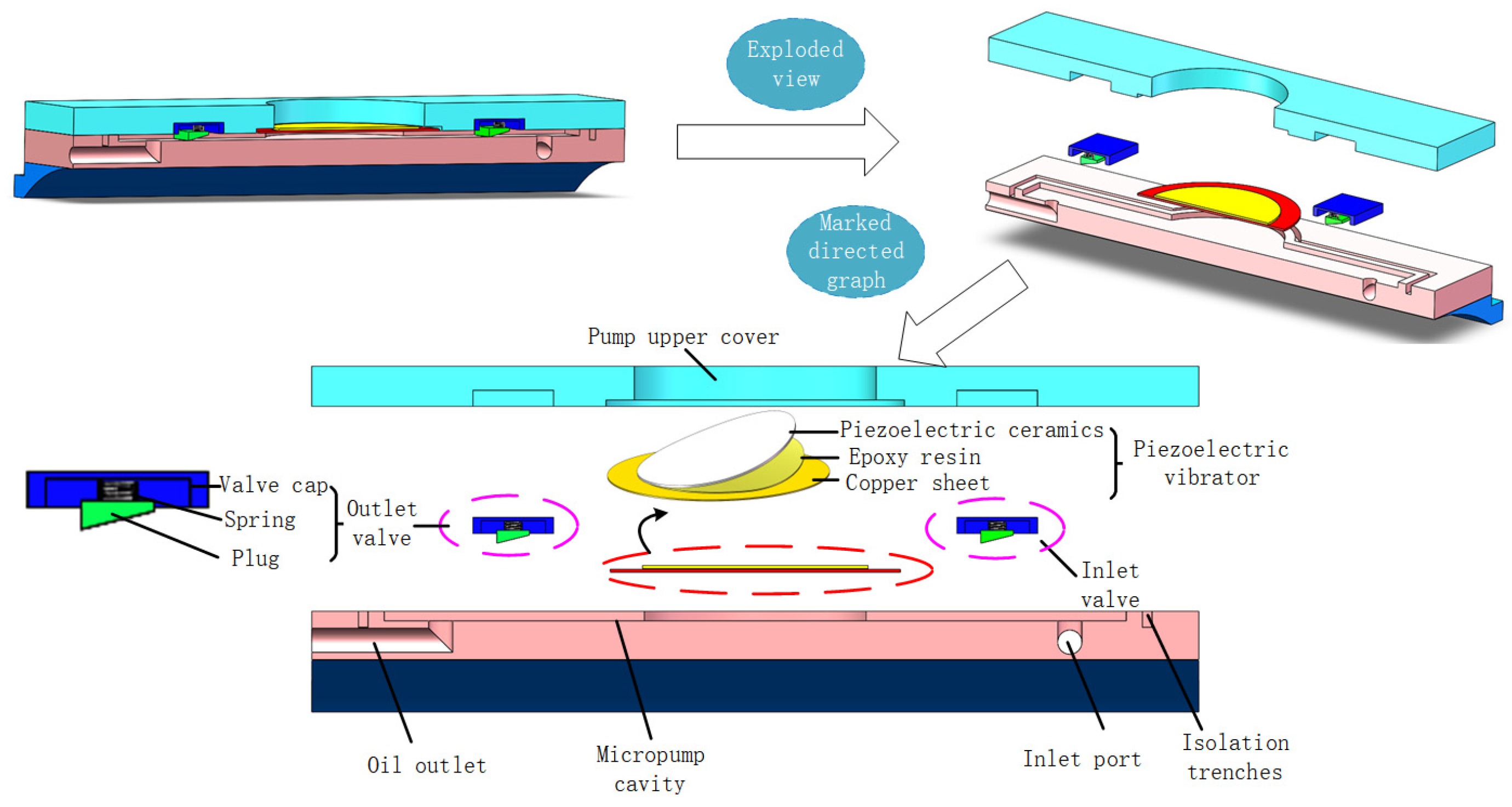
Figure 1. Piezoelectric micropump with moving valve.
Actuators 14 00227 g001
Figure 2. Active lubrication principle diagram.
Actuators 14 00227 g002
Figure 3. Micropump photos and dimensions.
Actuators 14 00227 g003
Figure 4. Modal analysis diagram of micropump.
Actuators 14 00227 g004
Figure 5. Oscillator deformation diagram.
Actuators 14 00227 g005
Figure 6. Watershed grid division diagram.
Actuators 14 00227 g006
Figure 7. Pressure diagram of micropump cavity.
Actuators 14 00227 g007
Figure 8. Flow rate of pump at different time.
Actuators 14 00227 g008
Figure 9. Total pumping amount at different time.
Actuators 14 00227 g009
Figure 10. Pumping performance tests of the designed valveless piezoelectric micropump under different conditions: (a,b) pumping performance tests when different voltage amplitudes are applied; (c,d) the pumping performance tests of pumping fluids with different viscosities.
Actuators 14 00227 g010
Figure 11. Experimental platform system.
Actuators 14 00227 g011
Figure 12. Experimental pumping capacity when different voltage amplitudes are applied.
Actuators 14 00227 g012
Figure 13. Experimental pumping capacity when pumping fluids with different viscosities.
Actuators 14 00227 g013
Figure 14. (a) Volume of pumped droplets at different frequencies. (b) Flow rate of lubricating oil at different frequencies.
Actuators 14 00227 g014
Figure 15. Flow chart of the experiment.
Actuators 14 00227 g015
Figure 16. Variation of bearing friction torque with applied voltage pulse.
Actuators 14 00227 g016
Figure 17. Friction torque at different speeds when the voltage amplitude is 120 V.
Actuators 14 00227 g017
Figure 18. Experimental pulse number, theoretical pulse number, and error under different voltages.
Actuators 14 00227 g018
Figure 19. Number of experimental pulses and theoretical pulses and errors at different bearing speeds.
Actuators 14 00227 g019
Disclaimer/Publisher’s Note: The statements, opinions and data contained in all publications are solely those of the individual author(s) and contributor(s) and not of MDPI and/or the editor(s). MDPI and/or the editor(s) disclaim responsibility for any injury to people or property resulting from any ideas, methods, instructions or products referred to in the content.