Abstract
The underwater unstructured environment poses new challenges for the miniaturization and flexibility of underwater vehicles. This paper proposes a method of using micrometer-scale vibrations of piezoelectric vibrators to drive macroscopic jets. Then, we use two coupled piezoelectric jet driving units to construct a miniature underwater vehicle. Numerical simulation is used to investigate the flow field characteristics of coupled jets. Finally, the impact of the angle between the two piezoelectric jet drive units on the propulsion force is analyzed. The miniature underwater vehicle measures 77.8 mm in length and 87 mm in width. While achieving miniaturization, it maintains high flexibility, maneuverability, and controllability. By adjusting the input signals to the two piezoelectric jet drive units, the miniature underwater vehicle can move in a straight line, turn, and rotate. Its maximum linear velocity reaches 54.23 mm/s. Its outstanding motion ability and environmental adaptability allow it to perform various tasks in unknown and complex environments. It also has broad application prospects.
1. Introduction
Underwater vehicles play an important role in environmental surveys, water quality monitoring, seafloor and deep-sea exploration, marine species monitoring, and data collection. They are vital for ocean exploration and underwater operations [1]. In recent years, the growing commercial and industrial use of underwater vehicles has increased. Operating in unknown and complex environments poses new challenges. These include inspecting underwater infrastructure, like complex pipelines, exploring and sampling the seafloor with reefs and narrow spaces, monitoring underwater cave systems or archaeological sites, and even conducting exploration in harsh deep-sea environments [2]. To accomplish tasks in the aforementioned environments, underwater vehicles must possess a combination of high maneuverability, pressure resistance, compact size, and stable transmission systems in order to better adapt to unstructured spaces.
Among the essential attributes of underwater vehicles, miniaturization, which refers to compactness, is a prerequisite for achieving other attributes. In research on miniaturizing underwater vehicles, functional materials are widely used in their design. Actuators made from these materials are compact, and their sealing and pressure-resistant structures are simple. They can directly convert electrical energy into mechanical energy. These characteristics help achieve underwater vehicle miniaturization. The current research on underwater vehicle actuators shows three main directions in the application of functional materials: shape memory alloys (SMAs), Piezoelectric Transducers (PZTs), and Electroactive Polymers (EAPs) [3]. EAPs include dielectric elastomers (DEs) and Ionic Polymer Metal Composites (IPMCs). For propulsion modes, underwater robots using these materials mostly adopt two bionic methods: body/caudal fin swimming (BCF) and median/paired fin swimming (MPF) [4]. They use biomimetic fin structures for power output. Notably, compared to the two mainstream propulsion modes mentioned earlier, underwater robots designed based on jet propulsion principles have not yet garnered sufficient research attention.
For example, Raphael Tsimbo Fokou et al. [5] designed a soft robotic fish driven by artificial muscles composed of SMA and printed circuit boards, with a length of 280 mm. Qian et al. [6] presented a miniature swimmer driven by a PZT ring ultrasonic underwater propulsion system. It is 7 mm in both length and diameter, with a speed of 19.79 mm/s. Borgen et al. [7] designed a miniature robotic fish. It is driven by a mechanism powered by two piezoelectric bending beam actuators. The maximum swimming speed of the robotic fish can reach 0.25 m/s. Wang et al. [8] designed a spherical swimming robot powered by a piezoelectric inertial motor, with a diameter of only 50 mm. Takesue et al. [9] presented a micro-underwater robot equipped with a vibrating motor. It can reach a speed of 127 mm/s. Zhang et al. [10] designed a manta ray-like flexible underwater robot based on bending dielectric elastomers. Its maximum length is no more than 6 mm. Berlinger et al. [11] presented a mini-robotic fish driven by a fin-like dielectric elastomer actuator. The fish is 100 mm long, 30 mm wide, and 60 mm high. Guo et al. [12] proposed a hybrid underwater micro-robot using an Ionic Conducting Polymer Film (ICPF) actuator. It is 45 mm long and 10 mm wide. Sun et al. [13] designed a centimeter-scale bionic robotic turtle based on an IPMC actuator. The turtle’s maximum length is 9.5 cm. Chen et al. [14] designed a robotic fish driven by a magnetic actuator. It can swim quickly and turn flexibly, and it is 89 mm long. Liao et al. [15] designed a bionic robot fish with an integrated vibration and jet propulsion mechanism. The fish is 100 mm long and 30 mm in diameter. Wang et al. [16] designed a mini-jellyfish-like robot with a diameter of 110 mm and a height of 140 mm. Valdastri et al. [17] designed a mini-swimming robot propelled by the interaction of permanent magnets. The robot is 35 mm long and 18 mm wide.
Compared with the BCF and MPF swimming modes, jet propulsion has a faster response, simpler control, and is easier to implement. In addition to the above, the jet propulsion mode, as opposed to the BCF and MPF swimming modes, responds faster and is simpler to control. When designing underwater actuators based on the jet propulsion mode, the internal cavity with variable volume needs to connect with the outside fluid. As a result, the inner and outer structures of the actuator are interconnected, and the pressure difference between the internal and external environment is less affected by the outside. If the design is reasonable, the actuator can theoretically possess high-pressure resistance. However, underwater actuators that use other propulsion modes have difficulty achieving such high-pressure resistance [18,19,20]. At present, research on the jet propulsion mode of underwater robots driven by functional material actuators mainly focuses on bionic jellyfish or squids. For example, Hamidi et al. [21] developed a bionic jellyfish driven by a twisting and curling polymer actuator. Yang et al. [22] designed a cuttlefish robot leveraging the muscle-like properties of dielectric elastomers. Tang et al. [23] created a cephalopod robot based on dielectric elastomer jet actuators. Ulloa et al. [24] designed a jellyfish robot using shape memory alloy springs as actuators. Barbar et al. [25] proposed a jellyfish robot propelled by an ionic polymer–metal composite actuator. Godaba et al. [26] developed a jellyfish robot powered by a dielectric elastomer actuator. Wang et al. [27] designed a bionic jellyfish robot driven by a shape memory alloy. These jet-propulsion-mode jellyfish robots, though centimeter-scale in structure, have only one jet chamber. Thus, they can only move in a single direction, which results in low flexibility, low maneuverability, and poor controllability. We assume that multiple jet chambers are arranged on the robot. These jet chambers can coordinate with each other to drive the robot to move. This may greatly enhance the robot’s flexibility, maneuverability, and controllability.
The existing jet-propulsion-mode robots are mostly actuated by shape memory alloys and dielectric elastomers. Their slow response speed does not meet our design requirements. Piezoelectric ceramics, with their fast response, high pressure resistance, and simple structure, meet our design requirements. But currently, piezoelectric jet technology is mostly used for fluid drag reduction, such as the piezoelectric drag reducers studied by Zhang et al. [28,29,30], and it is rarely used as a propulsion source for underwater vehicles.
Inspired by jellyfish movements, we propose using micrometer-scale vibrations of piezoelectric vibrators to drive macroscopic jets. Then, we develop a miniature underwater vehicle with two coupled piezoelectric jet drive units, applying piezoelectric jet drive in underwater vehicles. The miniature underwater vehicle, despite its small size, boasts high flexibility, maneuverability, and controllability. It is capable of moving in straight lines, turning, and rotating. As piezoelectric jet drive units directly use actuators as executors without transmission systems and dynamic seals, they eliminate transmission-system failure rates, energy-loss issues, and the risk of overall system failure caused by dynamic seal failure. This significantly improves the stability of micro-vehicles in complex and harsh environments.
The rest of this paper is organized as follows. The second part introduces the structural design of the piezoelectric jet drive unit and the miniature underwater vehicle. In the third part, numerical simulation is used to analyze the principle of multi-unit coupled jet driving and the optimal driving angle. It also presents a motion control strategy for the miniature underwater vehicle. The fourth part tests the motion performance of the miniature underwater vehicle. Finally, the fifth part offers conclusions and an outlook.
2. Structural Design
Figure 1 presents the structural design of the miniature underwater vehicle and piezoelectric jet drive units. The miniature underwater vehicle comprises an upper shell, a buoyancy block, a lower shell, and two piezoelectric jet drive units, whose nozzles face inward and are positioned 100° apart. The piezoelectric jet drive unit comprises a unit housing, piezoelectric ceramic, copper sheets, and a jet chamber. We bonded the piezoelectric ceramic and epoxy resin on the copper sheet to form a piezoelectric vibrator. Epoxy resin was applied to the outer cylindrical surface of the copper sheet. This secured the piezoelectric vibrator to the jet chamber, forming a jet cavity. Based on the converse piezoelectric effect of piezoelectric ceramics, the piezoelectric vibrator undergoes bending deformation when excited by an AC signal. This changes the volume of the jet chamber, enabling fluid to be drawn in or expelled, thereby achieving the driving function. Coating the piezoelectric vibrator with soft silicone allows it to be used underwater without additional sealing devices. This greatly reduces the size of the miniature underwater vehicle.
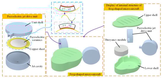
Figure 1.
Structural design of the miniature underwater vehicle and the piezoelectric jet drive unit.
3. Multi-Unit Underwater Coupled Jet Propulsion Mechanism and Motion Control Strategy for the Miniature Underwater Vehicle
3.1. Multi-Unit Underwater Coupled Jet Propulsion Mechanism
Based on the converse piezoelectric effect of piezoelectric ceramics, the piezoelectric vibrator generates bending deformation under AC signal excitation. This deformation changes the jet chamber volume, thereby drawing in or expelling fluid to achieve the driving function. The driving process of the piezoelectric jet drive unit involves the multi-field coupling of electricity, structure, and fluid. Thus, a bidirectional fluid–structure coupling model was established using the commercial software Ansys Workbench 18.2, as shown in Figure 2. Structural dynamics simulation was performed using the Transient Structural module. A flow field characterization simulation was conducted with the Fluent module. Data exchange for fluid–structure coupling analysis was handled by the System Coupling module. Finally, CFD-Post was used for post-processing and result analysis.
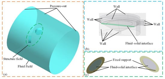
Figure 2.
Simulation model. (a) Fluid domain and domain model. (b) Fluid domain boundary conditions. (c) Domain boundary conditions.
After the flow field reaches a steady state, changes in the piezoelectric vibrator and flow field characteristics at different time points within a cycle are selected, as shown in Figure 3a,b. From 0 to 0.5 T is the ejection phase. The piezoelectric vibrator deforms in the direction shown in the figure. The jet chamber volume decreases gradually. Fluid is ejected through the nozzle. Because of the shearing effect between the ejected fluid and the surrounding stationary fluid, vortex rings form at positions A and B. Over time, the two vortex rings at position A gradually enlarge, move inward, interact upon contact, and eventually dissipate. The vortex ring at position B moves outwards and grows. It continuously entrains surrounding fluid, forming a high-momentum jet that propels the miniature underwater vehicle. The two vortex rings eventually move away from the miniature underwater vehicle and dissipate slowly. From 0.5 T to T is the suction phase. The piezoelectric vibrator deforms in the direction shown in the figure. The volume of the jet chamber increases gradually. Fluid is first sucked into the chamber along the axis of the nozzle. Similarly, vortex rings form at positions A and B due to the shearing effect between the sucked in fluid and the surrounding stationary fluid. Fluid continues to be drawn into the chamber along the bottom of the jet chamber. Over time, the vortex ring at position A still slowly moves inward and gradually dissipates. Unlike the ejection phase, the vortex ring at position B moves inward during the suction phase. Before the two vortex rings meet, they both increase in size. After they meet, their interaction causes them to shrink and eventually dissipate into the fluid. During the suction phase, the vortex ring also entrains surrounding fluid to form a jet, propelling the miniature underwater vehicle. Because of the continuous ejection and suction, the miniature underwater vehicle can maintain continuous motion.
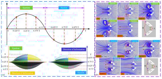
Figure 3.
Flow field characteristics of the underwater coupled jet in one cycle. (a) The change I the piezoelectric vibrator with time. (b) The flow field of the multi-unit underwater coupled jet at different time points.
3.2. Analysis of the Optimal Angle of the Multi-Unit Underwater Coupled Jet
Figure 4b presents the miniature underwater vehicle and its simplified mathematical model. In the diagram, the propulsion force F from the piezoelectric jet drive unit is perpendicular to the jet chamber’s bottom. The force driving the miniature underwater vehicle is the x-axis component Fx of F. Let α be the angle between the two piezoelectric jet drive units. The angle between F and Fx is π/2 − α/2. So, Fx = F cos (π/2 − α/2). As α increases, Fx increases. That is, the larger the angle, the greater the propulsion force. To verify this, a numerical simulation was used to calculate the propulsion force of the multi-unit coupled underwater jets at different angles. In this study, we maintained an aspect ratio of 0.6–0.9. Angle changes can affect the total width of the miniature underwater vehicle. So, to meet the aspect ratio requirement, our angle analysis ranged from 80° to 120°. The simulation method is the same as in Section 3.1. After the calculation, the x-axis force on the jet chamber bottom was extracted in CFD-Post as the driving force. Then, the driving force was integrated and averaged to obtain the average driving force. The average propulsion force at different angles is shown in Figure 4a. As can be seen in the figure, as the angle increases, the average propulsion force also increases, which corroborates the earlier findings. Theoretically, a larger angle is better. When α is 120°, the average propulsion force is maximized, but so is the flow resistance. When the drag force and propulsion increase proportionally, 90° is theoretically the optimal angle. However, due to complex fluid interactions from the structure, our tests found 110° to be optimal. Thus, we selected 100° as the angle between the two piezoelectric jet drive units for further experiments.
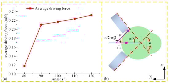
Figure 4.
Multi-unit underwater coupled jet optimal angle analysis. (a) Average propulsion force at various angles. (b) Mathematical model.
3.3. Motion Control Strategy of the Miniature Underwater Vehicle
The miniature underwater vehicle achieves multi-mode motion through coordinated voltage control of the two piezoelectric jet drive units, as shown in Figure 5. When the same voltage is applied to the two piezoelectric jet driving units, the driving units produce equal propulsion force. The equal driving force on both sides enables the micro-underwater vehicle to move stably on a straight line (The linear motion video can be found in Part I of the Supplementary Material Video S1 included with this article). By creating an asymmetric thrust distribution through adjusting the voltage difference between the two sides, the miniature underwater vehicle can perform turning movements (The turning motion video can be found in Part I of the Supplementary Material Video S1 included with this article). In obstacle avoidance scenarios, instantaneously cutting off the voltage input to one piezoelectric jet drive unit can trigger a rotation around a fixed point. Once the vehicle has turned to the desired angle, restoring the symmetrical voltage to both units can rebuild a straight-line trajectory (detailed sports videos can be found in Part I of the Supplementary Material Video S1 included with this article).
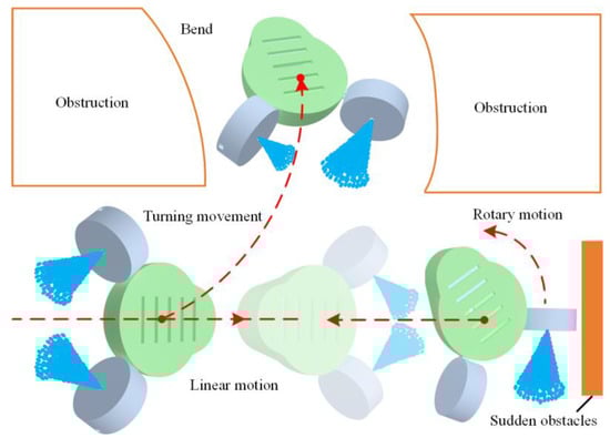
Figure 5.
Multiple motion modes of the miniature underwater vehicle.
4. Motion Performance Test of the Miniature Underwater Vehicle
The multiple motion modes of the miniature underwater vehicle are achieved through the coordination of two piezoelectric jet drive units. The performance of these units depends on the vibration characteristics of the piezoelectric vibrator, which is controlled by an excitation signal with two key parameters: voltage and frequency. As the piezoelectric jet drive unit has an optimal working frequency, it can achieve maximum thrust when operating at this frequency. First, we examined the linear velocity of the miniature underwater vehicle at different frequencies with a constant voltage to determine the optimal working frequency of the piezoelectric jet drive unit. Next, we explored how varying voltages affect linear velocity, rotational angular velocity, turning angular velocity, and turning radius when the frequency is constant.
The relationship between the linear velocity of the miniature underwater vehicle and frequency at 150 Vp-p voltage is shown in Figure 6a. In the figure, the linear velocity first increases and then decreases with increasing frequency. The maximum linear velocity is obtained at 110 Hz, indicating that the optimal working frequency of the piezoelectric jet drive unit is around 110 Hz. In the following experiments, 110 Hz was used as the fixed working frequency to study the motion performance of the miniature underwater vehicle at different voltages. Figure 6b presents the relationship between linear velocity and voltage. It shows that the linear velocity of the miniature underwater vehicle increases with the voltage. A maximum linear velocity of 54.23 mm/s is achieved at 210 Vp-p. This is probably because, at higher excitation voltages, piezoelectric vibrators achieve larger vibration amplitudes. This makes piezoelectric jet drive units generate higher thrust. In practical applications, the movement speed of miniature underwater vehicles can be adjusted by changing the voltage. As can be seen in Figure 6c, the rotational angular velocity increases with the voltage applied to the outer piezoelectric jet drive unit. A maximum rotational angular velocity of 1.17 rad/s is achieved at 210 Vp-p. This excellent rotational capability allows the miniature underwater vehicle to make quick turns when encountering obstacles during movement. In the turning-characteristic experiment of the miniature underwater vehicle, the voltage ratio of the outer piezoelectric jet drive unit to the inner piezoelectric jet drive unit was 1.07–1.47. We measured the cornering angular velocity and radius at different voltages, with the results presented in Figure 6d. As can be seen, the rotational angular velocity increases with the voltage, reaching a maximum of 0.99 rad/s. Meanwhile, the turning radius decreases with increasing voltage, with a minimum of 40 mm. This small turning radius allows the miniature underwater vehicle to navigate flexibly through narrow and tortuous pipelines or crevices.
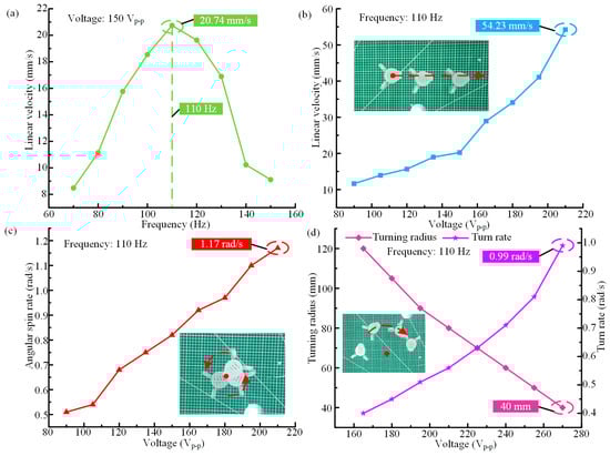
Figure 6.
Motion characteristics test of the miniature underwater vehicle. (a) The relationship between linear velocity and frequency at a voltage of 150 Vp-p. (b) The relationship between linear velocity and voltage at 110 Hz. (c) The relationship between the rotational angular velocity and voltage at a frequency of 110 Hz. (d) The relationship between turning angular velocity, turning radius, and voltage when the frequency is 110 Hz.
5. Performance Comparison
To demonstrate the superior performance and applicability of the miniature underwater vehicle, we compared it with other robots in terms of size, speed, and locomotion, as shown in Table 1.

Table 1.
Comparison with existing designs.
6. Conclusions
The underwater unstructured environment demands that underwater vehicles have a small size and high flexibility. This paper presents a multi-unit underwater coupled jet method. Numerical simulations show that the periodic ejection and suction of fluid by piezoelectric jet drive units create vortex rings. These rings entrain surrounding fluid, forming high-momentum jets that propel the miniature underwater vehicle. Based on a multi-unit underwater coupled jet method, a miniature underwater vehicle was designed by arranging two piezoelectric jet drive units at an angle. In order to study the influence of the angle between the units on the propulsion force, we established a mathematical model and then verified it by a numerical simulation. The results indicated that the propulsion force increases with the angle between the units.
By applying different excitation signals to the two piezoelectric jet drive units, the miniature underwater vehicle can achieve linear, turning, and rotational motions. In order to test the motion performance of the micro-underwater vehicle, we developed a prototype of the micro-underwater vehicle. When the same excitation signals are applied to both piezoelectric jet drive units, the vehicle moves linearly, achieving a maximum linear velocity of 54.23 mm/s. When an excitation signal is applied to only one piezoelectric jet drive unit, the miniature underwater vehicle rotates, achieving a rotational angular velocity of up to 1.17 rad/s. When different excitation signals are applied to the two piezoelectric jet drive units, the miniature underwater vehicle turns. Its maximum turning angular velocity is 0.99 rad/s, and its minimum turning radius is 40 mm. Its outstanding motion and environmental adaptability make the miniature underwater vehicle capable of performing various tasks in unknown and complex environments, acting as an excellent executor. In the future, we will try to add buoyancy adjustment modules and control systems to achieve cable-free control.
Supplementary Materials
The following supporting information can be downloaded at: https://www.mdpi.com/article/10.3390/act14050244/s1, Video S1: Miniature underwater vehicle Structure and motion demonstration.
Author Contributions
D.Z.: writing—original draft, validation, supervision, software, resources, funding acquisition, and funding acquisition. X.M.: data curation. X.Z.: formal analysis. P.G.: project administration. K.L.: writing—review and editing, visualization, and validation. All authors have read and agreed to the published version of the manuscript.
Funding
This work was supported in part by the Natural Science Foundation of Heilongjiang Province, China (Grant No. YQ2023E011).
Data Availability Statement
Data are contained within the article and Supplementary Materials.
Conflicts of Interest
Authors Dong Zhang and Xingming Ma were employed by the company State Grid Heilongjiang Electric Power Co., Ltd., Daqing Power Supply Company. Author Xue Zhang was employed by the company Shandong Electricity & Electricity Hitachi High Voltage Switchgear Co., Ltd., Author Peng Gao was employed by the company Harbin Kangyuan Multi-Dimensional Technology Development Co, Ltd. The remaining author declares that the research was conducted in the absence of any commercial or financial relationships that could be construed as a potential conflict of interest.
References
- Xing, J.; Jin, W.; Yang, K.-H.; Howard, I.M. A Bionic Piezoelectric Robotic Jellyfish with a Large Deformation Flexure Hinge. IEEE Trans. Ind. Electron. 2023, 70, 12596–12605. [Google Scholar] [CrossRef]
- Zhou, X.X.; Zhang, L.; Chen, W.S.; Liang, Q.W.; Liu, B.; Zheng, H.Y.; Li, K. Study of an Untethered Bioinspired Piezoelectric Father-Son Robot for Deep-Sea Narrow Space. IEEE Trans. Ind. Electron. 2024, 12, 16108–16119. [Google Scholar] [CrossRef]
- Chu, W.S.; Lee, K.T.; Song, S.H.; Han, M.W.; Lee, J.Y.; Kim, H.S.; Kim, M.S.; Park, Y.J.; Cho, K.J.; Ahn, S.H. Review of biomimetic underwater robots using smart actuators. Int. J. Precis. Eng. Manuf. 2012, 13, 1281–1292. [Google Scholar] [CrossRef]
- Wang, R.; Wang, S.; Wang, Y.; Cheng, L.; Tan, M. Development and Motion Control of Biomimetic Underwater Robots: A Survey. IEEE Trans. Syst. Man Cybern. Syst. 2022, 52, 833–844. [Google Scholar] [CrossRef]
- Fokou, M.R.T.; Xia, Q.R.; Jin, H.; Xu, M.; Dong, E.R. A Soft Robotic Fish Actuated by Artificial Muscle Modules (SoRoFAAM-1). J. Bionic Eng. 2023, 20, 2030–2043. [Google Scholar] [CrossRef]
- Qian, Y.; Kong, D.Q.; Nagasaki, D.; Aoyagi, M.; Kurosawa, M.K. A miniature swimmer actuated by a PZT ring ultrasonic underwater propulsion system. Jpn. J. Appl. Phys. 2024, 63, 7. [Google Scholar] [CrossRef]
- Borgen, M.G.; Washington, G.N.; Kinzel, G.L. Design and evolution of a piezoelectrically actuated miniature swimming vehicle. IEEE-ASME Trans. Mechatron. 2003, 8, 66–76. [Google Scholar] [CrossRef]
- Wang, L.; Hou, Y.J.; Zhao, K.D.; Shen, H.; Wang, Z.W.; Zhao, C.S.; Lu, X.L. A novel piezoelectric inertial rotary motor for actuating micro underwater vehicles. Sens. Actuator A-Phys. 2019, 295, 428–438. [Google Scholar] [CrossRef]
- Takesue, N.; Mitsuzumi, T.; Nagasawa, M. Proposal of miniature aquatic robot utilizing resonance of elastic plate. In Proceedings of the 2015 IEEE International Conference on Advanced Intelligent Mechatronics (AIM), Busan, Republic of Korea, 7–11 July 2015; pp. 1719–1724. [Google Scholar]
- Zhang, C.; Zhang, C.; Qu, J.; Qian, X. Underwater and Surface Aquatic Locomotion of Soft Biomimetic Robot Based on Bending Rolled Dielectric Elastomer Actuators. In Proceedings of the 2023 IEEE/RSJ International Conference on Intelligent Robots and Systems (IROS), Detroit, MI, USA, 1–5 October 2023; pp. 4677–4682. [Google Scholar]
- Berlinger, F.; Duduta, M.; Gloria, H.; Clarke, D.R.; Nagpal, R.; Wood, R.J. A Modular Dielectric Elastomer Actuator to Drive Miniature Autonomous Underwater Vehicles. In Proceedings of the 2018 IEEE International Conference on Robotics and Automation (ICRA), Brisbane, Australia, 21–25 May 2018; pp. 3429–3435. [Google Scholar]
- Guo, S.; Okuda, Y.; Zhang, W.; Ye, X.; Asaka, K. The development of a hybrid underwater micro biped robot. Appl. Bionics Biomech. 2006, 3, 143–150. [Google Scholar] [CrossRef]
- Sun, Q.M.; Han, J.Z.; Li, H.; Liu, S.; Shen, S.N.; Zhang, Y.F.; Sheng, J.Z. A Miniature Robotic Turtle With Target Tracking and Wireless Charging Systems Based on IPMCs. IEEE Access 2020, 8, 187156–187164. [Google Scholar] [CrossRef]
- Chen, X.; Wu, Z.; Zhou, C.; Yu, J. Design and Implementation of a Magnetically Actuated Miniature Robotic Fish. IFAC-PapersOnLine 2017, 50, 6851–6856. [Google Scholar] [CrossRef]
- Liao, P.; Zhang, S.W.; Sun, D. A dual caudal-fin miniature robotic fish with an integrated oscillation and jet propulsive mechanism. Bioinspir. Biomim. 2018, 13, 15. [Google Scholar] [CrossRef]
- Wang, W.; Li, W.Q.; Xu, J.C.; Dong, J.W.; Xiang, C.Q.; Guan, Y.S.; Zhang, T. Design and Implementation of a Miniature Jellyfish-Inspired Robot. IEEE Robot. Autom. Lett. 2023, 8, 3134–3141. [Google Scholar] [CrossRef]
- Valdastri, P.; Sinibaldi, E.; Caccavaro, S.; Tortora, G.; Menciassi, A.; Dario, P. A Novel Magnetic Actuation System for Miniature Swimming Robots. IEEE Trans. Robot. 2011, 27, 769–779. [Google Scholar] [CrossRef]
- Li, K.; Zhou, X.X.; Liu, Y.X.; Sun, J.H.; Tian, X.Q.; Zheng, H.Y.; Zhang, L.; Deng, J.; Liu, J.K.; Chen, W.S.; et al. A 5 cm-Scale Piezoelectric Jetting Agile Underwater Robot. Adv. Intell. Syst. 2023, 5, 9. [Google Scholar] [CrossRef]
- Zhou, X.X.; Li, K.; Liu, Y.X.; Sun, J.H.; Li, H.Y.; Chen, W.S.; Deng, J. Development of an Antihydropressure Miniature Underwater Robot with Multilocomotion Mode Using Piezoelectric Pulsed-Jet Actuator. IEEE Trans. Ind. Electron. 2023, 70, 5044–5054. [Google Scholar] [CrossRef]
- Zhou, X.X.; Chen, W.S.; Li, K.; Zheng, H.Y.; Liu, B.; Chen, S.; Zhang, L.; Qi, N.M. A 7 cm-Scale Spherical Underwater Robot Using Piezoelectric Double-Jet Actuator for Deep-Sea Environment. IEEE-ASME Trans. Mechatron. 2023, 12, 3277–3288. [Google Scholar] [CrossRef]
- Singh, R.; Mohapatra, S.; Matharu, P.S.; Tadesse, Y.T. Twisted and coiled polymer muscle actuated soft 3D printed robotic hand with Peltier cooler for drug delivery in medical management. Acta IMEKO 2022, 11, 1–6. [Google Scholar] [CrossRef]
- Yang, T.; Xiao, Y.H.; Zhang, Z.; Liang, Y.M.; Li, G.R.; Zhang, M.Q.; Li, S.J.; Wong, T.W.; Wang, Y.; Li, T.F.; et al. A soft artificial muscle driven robot with reinforcement learning. Sci. Rep. 2018, 8, 8. [Google Scholar] [CrossRef]
- Tang, C.; Ma, W.T.; Li, B.; Jin, M.L.; Chen, H.L. Cephalopod-Inspired Swimming Robot Using Dielectric Elastomer Synthetic Jet Actuator. Adv. Eng. Mater. 2020, 22, 1901130. [Google Scholar] [CrossRef]
- Ulloa, C.C.; Terrile, S.; Barrientos, A. Soft Underwater Robot Actuated by Shape-Memory Alloys “JellyRobcib” for Path Tracking Through Fuzzy Visual Control. Appl. Sci. 2020, 10, 7160. [Google Scholar] [CrossRef]
- Akle, B.; Najem, J.S.; Leo, D.J.; Blottman, J.B. Design and development of bio-inspired underwater jellyfish like robot using ionic polymer metal composite (IPMC) actuators. In Proceedings of the Smart Structures and Materials + Nondestructive Evaluation and Health Monitoring, San Diego, CA, USA, 6–10 March 2011. [Google Scholar]
- Godaba, H.; Li, J.; Wang, Y.; Zhu, J. A Soft Jellyfish Robot Driven by a Dielectric Elastomer Actuator. IEEE Robot. Autom. Lett. 2016, 1, 624–631. [Google Scholar] [CrossRef]
- Wang, Z.; Lin, X.; Feng, X.; Qin, H.; Xu, S. A motion simulation of bionic jellyfish based on shape memory alloy. In Proceedings of the 2017 36th Chinese Control Conference (CCC), Dalian, China, 26–28 July 2017; pp. 6590–6595. [Google Scholar]
- Zhang, L.; Lv, M.; Zhao, X.; Fan, H.; Xie, T.; Shan, X.; Li, K. Achieving travelling wave drag reduction by micro piezoelectric actuator. Int. J. Mech. Sci. 2024, 275, 109326. [Google Scholar] [CrossRef]
- Zhang, L.; Li, K.; Shan, X.B.; Zhai, Y.; Yan, S.; Xie, T. Active Drag Reduction for the Wall of Microunderwater Vehicles by Piezoelectric Actuated Drag Reducer. IEEE-ASME Trans. Mechatron. 2022, 27, 5981–5993. [Google Scholar] [CrossRef]
- Zhang, L.; Lv, M.F.; Zhao, X.X.; Fan, H.Y.; Xie, Z.J.; Li, K. Arrangement and Control Parameter Selection Methods of Piezoelectric Traveling Wave Drag Reducer. IEEE Trans. Ind. Electron. 2024, 11, 16264–16274. [Google Scholar] [CrossRef]
Disclaimer/Publisher’s Note: The statements, opinions and data contained in all publications are solely those of the individual author(s) and contributor(s) and not of MDPI and/or the editor(s). MDPI and/or the editor(s) disclaim responsibility for any injury to people or property resulting from any ideas, methods, instructions or products referred to in the content. |
© 2025 by the authors. Licensee MDPI, Basel, Switzerland. This article is an open access article distributed under the terms and conditions of the Creative Commons Attribution (CC BY) license (https://creativecommons.org/licenses/by/4.0/).