Article

Time-Varying Control Strategy for Asymmetric Thrust Flight of Multi-Engines Aircraft

1
School of Technology, Beijing Forestry University, Beijing 100083, China
2
School of Astronautics, Beijing Institute of Technology, Beijing 100081, China
3
School of Aeronautical Science and Engineering, Beihang University, Beijing 100191, China
*
Author to whom correspondence should be addressed.
Actuators 2025, 14(5), 222; https://doi.org/10.3390/act14050222
Submission received: 28 March 2025 / Revised: 25 April 2025 / Accepted: 28 April 2025 / Published: 29 April 2025
(This article belongs to the Section Aerospace Actuators)

Abstract

:
This paper proposes a time-varying pilot control strategy, which is suitable for asymmetric thrust flight of multi-engine aircraft caused by single engine failure. To address the critical issue of lateral imbalance caused by thrust asymmetry, pilot control models for inner-loop attitude-heading control under aileron input and command sideslip control under rudder input are developed. Taking the time-varying adaptive characteristics of the pilot and the changes in flight states induced by thrust asymmetry into account, an adaptive inner-loop attitude-heading control logic and a command sideslip control strategy are proposed. Subsequently, a time-varying pilot lateral control strategy model is established. Simulation results demonstrate that the proposed time-varying control strategy ensures stable and controllable heading and flight attitude effectively. When compared with human-in-the-loop flight experiments, the time-domain results reveal that the flight states exhibit similar trends. A time-varying aircraft-pilot couplings evaluation indicates a reduced susceptibility to pilot-induced oscillations, with both systems showing consistent behavior, verifying the reliability of the proposed time-varying control strategy. The proposed pilot model can assist and guide the pilot in completing control tasks during single-engine failure.

1. Introduction

Aero-engine failure is one of the major causes of flight accidents and is a significant risk to aviation safety [1,2]. The asymmetric thrust caused by frequent single-engine failures generates substantial yawing moments, which can disrupt the aircraft’s lateral stability. If not managed properly, this imbalance can quickly lead to loss of control [3].
Currently, research on asymmetric thrust caused by aero-engine failure focuses mainly on three areas: engine fault diagnosis, automatic thrust asymmetry compensation control, and asymmetric power flying quality evaluation. In the field of engine fault diagnosis, various methods based on both model-driven and data-driven approaches to detect faults using actual flight data and theoretical model simulations are proposed [4,5]. Reference [6] introduces a data-driven fault diagnosis framework for aero-engines that combines gated recurrent unit (GRU) dynamic networks with deep neural networks, enabling effective fault detection and identification. Reference [7] developed an aero-engine fault diagnosis system and validated the system performance evaluation indicators through Monte Carlo simulations. Regarding thrust asymmetry compensation control, thrust asymmetry technology has been successfully implemented in transport aircraft, such as the Boeing 777 [8], where it uses rudder deflection to counteract the yaw caused by asymmetric thrust and reduce heading deviation [9]. Reference [10] presents a fully automated compensation strategy for multi-engines aircraft experiencing asymmetric thrust, which provides excellent compensation for asymmetric thrust flight. Reference [11] proposes a compensation scheme using a model reference adaptive control method, which ensures that heading and flight attitude are maintained, thereby guaranteeing flight safety. In the area of asymmetric power flying quality evaluation, current studies mainly focus on handling and stability characteristics during single-engine failure, proposing key issues, such as minimum control speed [12], crosswind capability [13], and single-engine lateral-directional handling qualities [14]. These studies primarily analyze the impact of single-engine failure and compensation technologies from the aircraft’s perspective. However, the above studies have not yet fully considered the critical role of the pilot. In the context of asymmetric thrust caused by single-engine failure, the pilot plays a vital role in fault diagnosis and corrective actions, which are essential for ensuring the flight safety. Therefore, there is a need to investigate the pilot’s time-varying control behavior under thrust asymmetry and develop control strategy models.
The analysis and modeling of pilot behavior in the event of aircraft failures has become a prominent area of research. Hess [15] has developed a pilot fault-adaptive model. This model captures the pilot’s adaptability to changes in the controlled system by reflecting variations in the gain parameters within the control loop [16]. It provides a conceptual framework for studying time-varying pilot control and has been applied to a variety of complex issues, such as analyzing multi-axis flight control problems with highly coupled and nonlinear dynamics [17,18], “boundary-triggered” pilot-induced oscillations (PIO) [19], failure assessment in the flight control systems [20], and assessing potential loss of control risks [21].
In the case of asymmetric thrust caused by single-engine failure, the pilot’s control becomes more complex due to the disruption of lateral-axis balance and the presence of two-axis coupling. Existing time-varying pilot models are insufficient to fully address these challenges. To tackle this issue, the paper presents a time-varying control strategy model for the pilot under asymmetric thrust conditions. The key contributions are as follows:
(1)
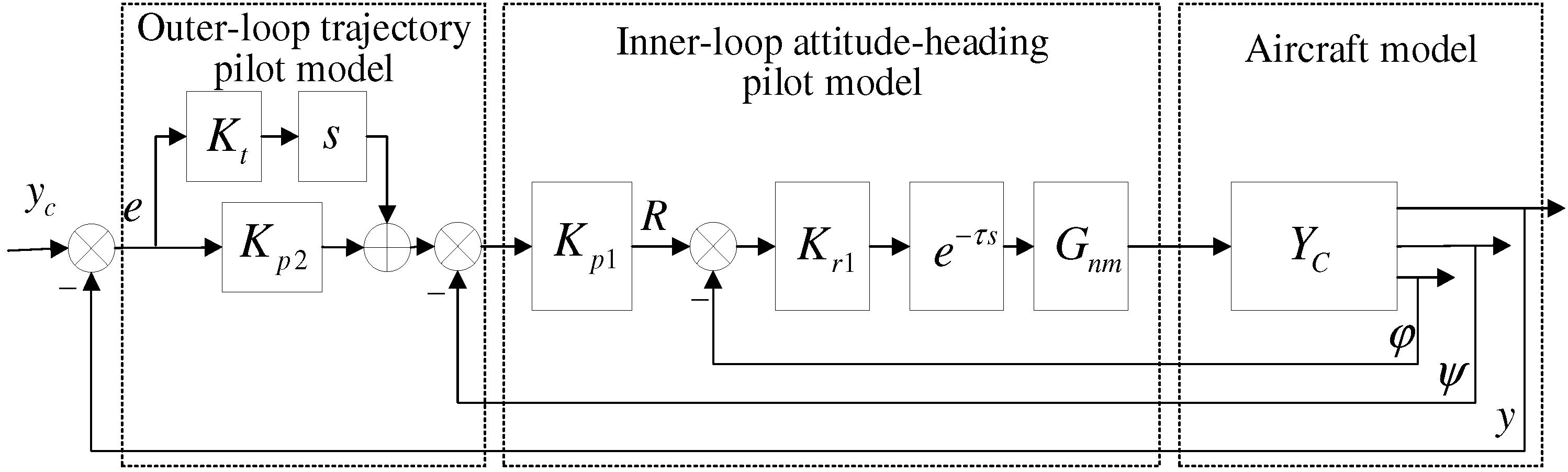
A multi-loop pilot control behavior model structure is developed to describe the pilot’s control behavior characteristics under lateral-directional imbalance caused by asymmetric thrust.
(2)
In response to the pilot’s control characteristics under asymmetric thrust, including inner-loop attitude-heading control and outer-loop trajectory control, a time-varying model for pilot control of aileron manipulation is established to analyze control behavior during an asymmetric thrust flight.
(3)
The proposed time-varying control strategy is evaluated by combining pilot-aircraft system simulations and pilot-in-the-loop flight experiments, in terms of both time-domain results and time-varying flying quality evaluations.

2. Analysis and Modeling of Pilot Control Behavior Under Asymmetric Thrust

When an aircraft is operating in an asymmetric thrust flight condition, both its longitudinal- and lateral-directional balance are disturbed. Due to the relatively small longitudinal imbalance, the pilot needs to adjust the elevator deflection to restore balance. However, addressing lateral-directional imbalance is more complex, as it involves the coupling between the two axes. Therefore, this paper primarily focuses on the study of lateral-directional control strategies under asymmetric thrust conditions.
In yaw control, when the pilot detects an engine failure, they should immediately apply full rudder deflection to minimize heading changes after the engine failure. As the heading change gradually decreases, the pilot can then maintain the desired sideslip angle by controlling the rudder, allowing the aircraft to continue flying with the commanded sideslip.
In roll control, the pilot uses the ailerons to control the roll, correct the heading, and eliminate lateral deviations. The inner-loop pilot control actions include both attitude and heading control. For attitude control, the pilot adjusts the ailerons based on changes in roll angle. For heading control, the pilot uses the ailerons to induce a roll, creating the necessary lateral acceleration through the lift component to change the heading. The outer-loop pilot control focuses on lateral deviation control, requiring the pilot to ensure the aircraft corrects its flight path during the flight.
Additionally, considering the cross-coupling feedback between the rudder and aileron signals, the pilot’s lateral-directional control system is shown in Figure 1. The following sections will introduce the models for the pilot’s aileron and rudder control under asymmetric thrust conditions.

2.1. Aileron Control Model for the Pilot Under Asymmetric Thrust Conditions

The aileron control model for the pilot under asymmetric thrust conditions consists of an inner-loop attitude-heading control model and an outer-loop trajectory control model. The inner-loop attitude-heading control model is based on the simplified single-loop pilot model proposed by Hess [15], and the model structure can be seen in Figure 2 as follows. This model provides a control-theoretic framework with which to study pilot control behavior in instances in which vehicle dynamics changes.
Considering that pilot control behavior under asymmetric thrust conditions differs from conventional control, it is necessary to improve Hess’s simplified single-loop pilot model. The improvements are primarily focused on the following two aspects:
Response Delay:
Hess’s time-varying pilot model does not account for pilot response delay. To address this, a delay element has been incorporated into the inner-loop of the pilot model to represent the pilot’s reaction time. Through extensive experimental analysis and data collection, the delay time has been determined to be 0.2 s [22,23]. It reflects the crossover model’s effective time delay.
Response to Error Magnitude and Rate of Change:
Based on pilot experience and frequency response analysis, the pilot is capable of responding not only to the magnitude of the error signal e but also to its rate of change e ˙ . While observing the magnitude of the error signal e, the pilot is also aware of how quickly it is changing. If the error rate of change increases, the pilot will anticipate and compensate for it to avoid excessive overshoot. Therefore, the pilot model should include a PD (Proportional–Derivative) element, which provides a stronger corrective response when the rate of change in the error signal is high, offering lead compensation, and has a minimal effect when the rate of change is slow.
Based on these improvements, the structure of the pilot aileron control model under asymmetric thrust conditions is shown in Figure 3 as follows.
In this model, Kr1 represents the gain parameter of the inner loop, which reflects the system’s damping ratio and the pilot’s behavior in quickly responding to the aircraft’s dynamic characteristics. Kp1 represents the gain parameter of the outer loop, influencing the open-loop crossover frequency of the pilot-aircraft system, with its adjustment primarily aimed at improving the system’s tracking performance. The PD element includes the gain parameter Kp2 and the derivative term Kts.
When an asymmetric thrust condition occurs due to an aero-engine failure, the changes in the outer loop trajectory are relatively slow, while the inner loop’s attitude and heading change more rapidly. As a result, the pilot’s control strategy primarily manifests in the inner loop’s attitude-heading control. By combining the time-varying pilot model with adaptive logic under fault conditions, the time-varying model of the pilot’s aileron control under asymmetric thrust is obtained, as shown in Figure 4.
In the figure, yc is the reference command signal to be tracked, y is the lateral displacement output, ψ is the yaw angle output, and ϕ is the roll angle output. The element represents a second-order model of the pilot’s neuromuscular system, as shown in Equation (1). The control parameters can be seen in [15]. The red arrow represents the aircraft encountering a single engine failure.
G n m = 10 2 s 2 + 2 ( 0.707 ) 10 s + 10 2
The basis for parameter adjustment using adaptive logic is the input R and output φ of the inner loop system. As defined in Figure 5, the variable x is related to the error of the inner loop system and x reflects the tracking performance of the inner loop. 1.5 2 s 2 + 2 × 1.5 s + 1.5 2 represents the filtering element.
Let the time of aero-engine failure be t c , and define the triggering factor K t r i g g e r as Equation (2).
K t r i g g e r = { 0 , i f x < 3 × r m s [ x ] o r   t < t c 1 ,       i f x 3 × r m s [ x ] a n d   t t c
In the equation, RMS represents the root-mean-square value. The adaptive variations of K r and K p are defined as Δ K r and Δ K p , respectively:
Δ K r = x K t r i g g e r
Δ K p = 0.35 Δ K r , Δ K r > 0 0 , Δ K r 0
Equation (2) illustrates the triggering principle of this adaptive logic: based on human physiological characteristics, human judgment follows a normal distribution, as shown in the literature. The principle of the normal distribution 3 σ states that, P ( μ 3 σ X μ + 3 σ ) = 99.7 % . The probability of values outside a certain range [ μ 3 σ , μ + 3 σ ] is less than 0.3%, making such events highly unlikely. Since the magnitude of x is related to the value of { R M ˙ } 2 , the trigger is determined by calculating x . Therefore, when the instantaneous value of x 3 r m s [ x ] and t t c , it can be considered that the pilot has judged the aircraft to be malfunctioning, indicating a change in the controlled object’s characteristics, and the adaptive logic is triggered ( K t r i g g e r = 1 ). Conversely, the adaptive logic will not be triggered ( K t r i g g e r = 0 ).

2.2. Pilot Rudder Control Model Under Asymmetric Thrust

In the rudder control channel, upon detecting an engine failure, the pilot should immediately apply full rudder to minimize the heading deviation resulting from the single-engine failure. As the aircraft’s heading change gradually stabilizes and decreases, the pilot should adjust the rudder based on the variation in the sideslip angle to ensure the aircraft performs the commanded sideslip flight. Therefore, the pilot’s rudder control model can be represented as follows.
δ r c = 0 t c < t t c + t f δ r max t c + t f < t t 1 ( K p β e τ s ) ( β c β ) t > t 1
In the equation, tf is the time interval during which the pilot adopts a control strategy after the engine failure; t1 is the time it takes for the aircraft’s heading change to gradually stabilize and decrease; δ r max is the maximum allowable rudder deflection towards the side of the engine that is still functioning; β c is the commanded sideslip angle; K p β is the gain by which the pilot adjusts the rudder based on the sideslip angle deviation; and e τ s represents the pilot’s response delay in the rudder control channel.

3. Results and Discussions

3.1. Analysis of Flight Motion Characteristics

The reference motion of the aircraft is a symmetrical steady straight flight before engine failure. When an aero-engine failure results in asymmetric thrust, the aircraft deviates from the original reference state, leading to sideslip and roll. Taking the case of a right aero-engine failure as an example, the aircraft’s lateral and directional motion characteristics are analyzed.

3.1.1. Analysis of Yaw Motion Characteristics

Due to the failure of the right engine, the yawing moment MzT is generated under the combined effect of the left engine thrust T1 and the drag D2 from the right engine that has stopped, as expressed by the following equation:
N z T = ( T 1 + D 2 ) L
In the equation, L is the distance from the engine axis to the aircraft’s centerline.
Under the effect of NzT, the aircraft’s nose deflects to the right. Due to inertia, the aircraft will maintain its original flight path, resulting in left sideslip and disrupting the aircraft’s directional balance.

3.1.2. Analysis of Lateral Motion Characteristics

When the right engine fails, the torque generated by the left engine’s thrust cannot be balanced, causing a positive roll torque M1. At the same time, the sideslip will cause the aircraft to lean toward the side of the failed engine, and the side force generated by the vertical tail will induce a positive roll torque M2. The left sideslip leads to an increase in the lift of the left wing and a decrease in the lift of the right wing. The resulting lift differential between the left and right wings generates a positive roll torque M3. The combined roll torque expression is as follows.
M z T = M 1 + M 2 + M 3

3.1.3. Analysis of Aircraft Characteristics Under Asymmetric Thrust

Select a specific model of a twin-engine aircraft as the example aircraft. The selected aircraft and engine data are consistent with those in reference [24]. The lateral state equations are written in the following form:
x ˙ = A l a t x + B l a t u + w l a t y ˙ = C l a t x
where the state variables are x = [ Δ β ˙ , Δ p ˙ , Δ r ˙ , Δ φ ˙ ]T, and the input variables are u = [ Δ δ a , Δ δ r ] . The system’s state matrix and input matrix are as follows.
A l a t = 0.0970 0.1518 0.9715 0.1269 1.5489 0.7825 0.7807 0 0.3531 0.1952 0.2513 0 0 1 0 0 ,   B l a t = 0 0.0451 0.8720 0.3810 0 0.7588 0 0 C l a t = 1 0 0 0 0 1 0 0 0 0 1 0 0 0 0 1
The lateral-directional state response of the aircraft under asymmetric thrust without applying the control is illustrated in Figure 6. From the simulation results, it can be observed that when asymmetric thrust occurs, the aircraft experiences left sideslip due to inertia and the yawing moment, with the sideslip angle being negative. Once the maximum sideslip angle is reached, the aircraft transitions from left sideslip to right sideslip. This is caused by the rolling moment, which tilts the aircraft and alters the direction of lift, causing the flight path direction to change more rapidly than the nose direction. As a result, the aircraft experiences yaw and lateral deviation. Without any control, the aircraft fails to meet performance requirements and enters an uncontrollable divergent state.

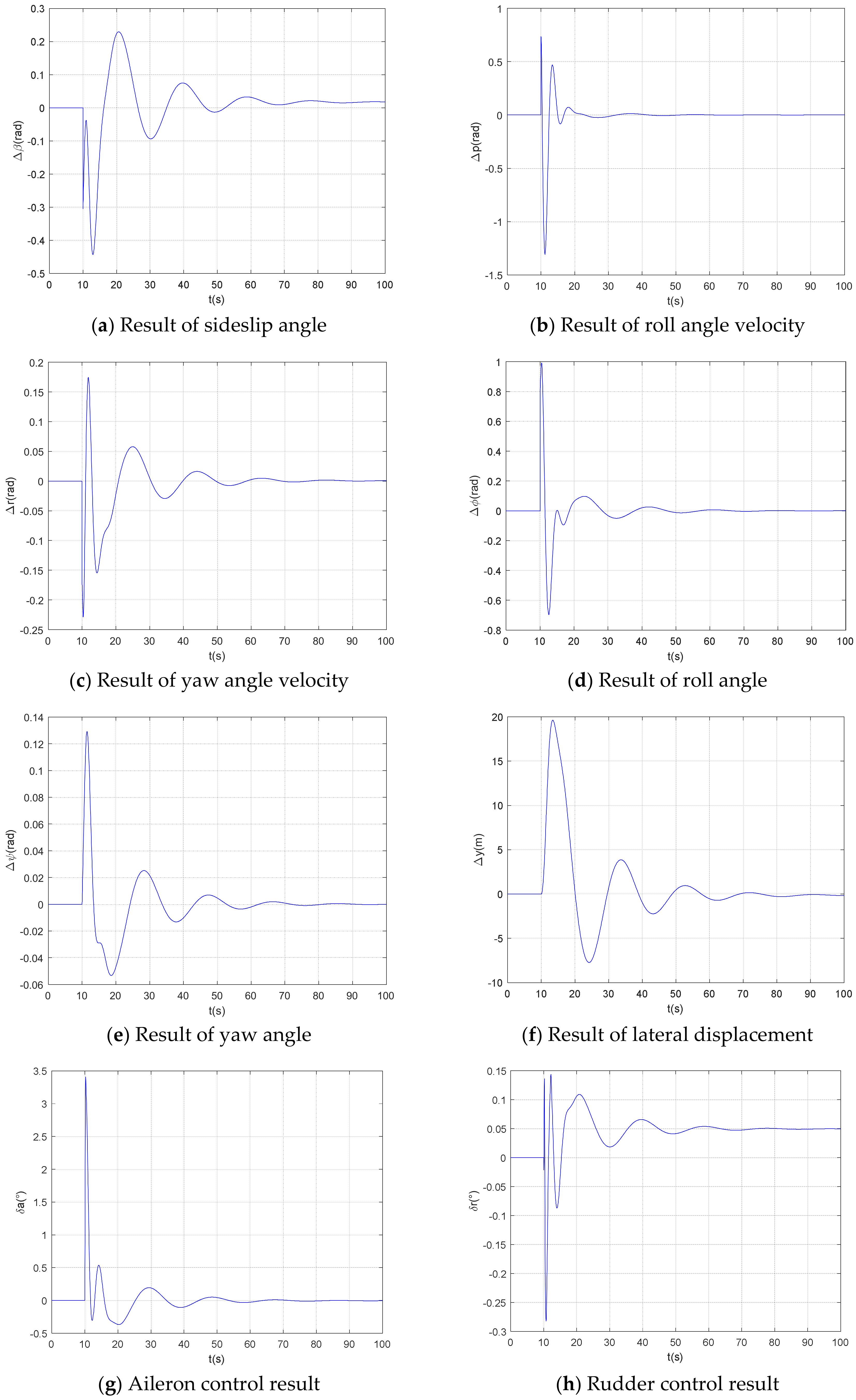
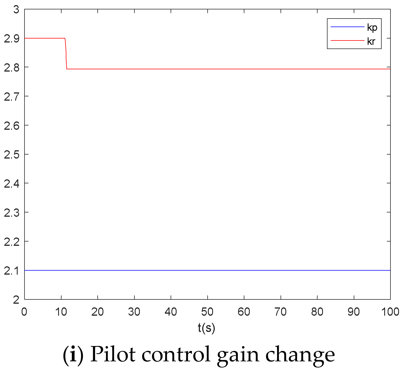
3.2. Pilot-Aircraft System Simulation and Analysis

The pilot model is integrated with the asymmetric thrust aircraft model to establish a pilot-aircraft system simulation model. The control of the aircraft is operated by the pilot, and the variation in its gain parameters also reflects nonlinear effects. The aero-engine failure occurs at 10 s, and the resulting flight state is shown in Figure 7a–f. As seen, after the aero-engine failure (at 10 s), the aircraft’s flight states (such as sideslip angle, roll angle, yaw angle, and lateral displacement) change and then stabilize. It is evident that the pilot model is able to maintain the aircraft’s flight stability after the failure occurs. The results of aileron and rudder control inputs are shown in Figure 7g,h. It can be observed that the pilot changes the control strategy after the failure and then stabilizes the control inputs. Figure 7i illustrates the changes in the pilot’s control gains. After the engine failure, the pilot’s inner-loop gain Kr decreases, and through adaptation to the sudden fault, the pilot gradually adjusts the gain to maintain stable control of the aircraft. The pilot’s control behavior characteristics in the lateral-directional imbalance state caused by asymmetric thrust are described.
Comparing with Figure 6, it can be observed that, after asymmetric thrust is applied, the initial phase also shows left sideslip due to inertia and yawing moment when the control method proposed in this paper is used (Figure 7a). At this point, the pilot detects the fault based on the change in sideslip angle and adjusts the rudder accordingly (Figure 7h), ensuring that the aircraft follows the commanded sideslip mode. Simultaneously, the rolling moment causes a deviation in the aircraft’s roll angle (Figure 7d). The pilot, utilizing the designed adaptive logic, controls the ailerons (Figure 7g), stabilizing the roll angle and angular velocity (Figure 7b), eliminating lateral deviation (Figure 7f), and keeping the wings level while maintaining the commanded sideslip. This ensures the aircraft’s stability, preventing divergence and loss of control.

4. Experimental Validation

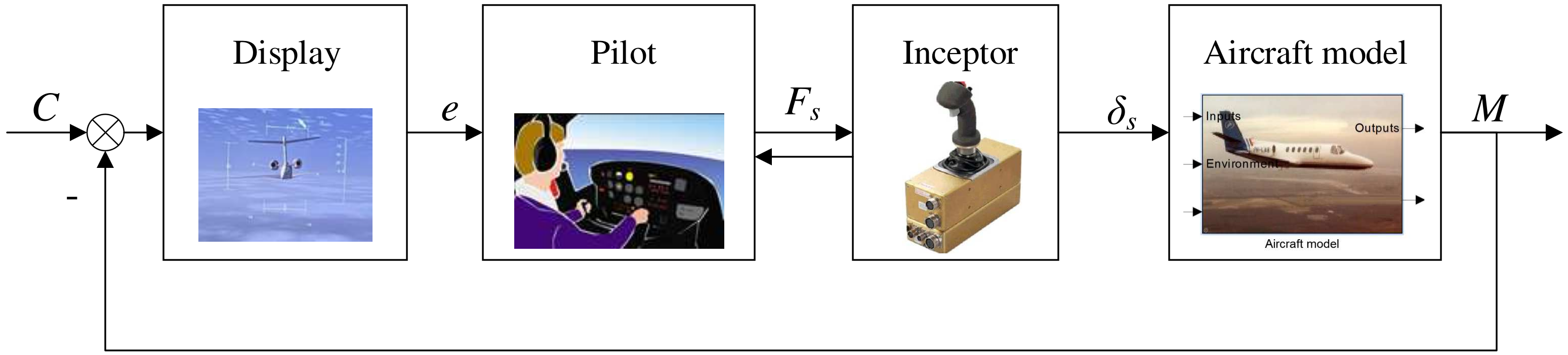
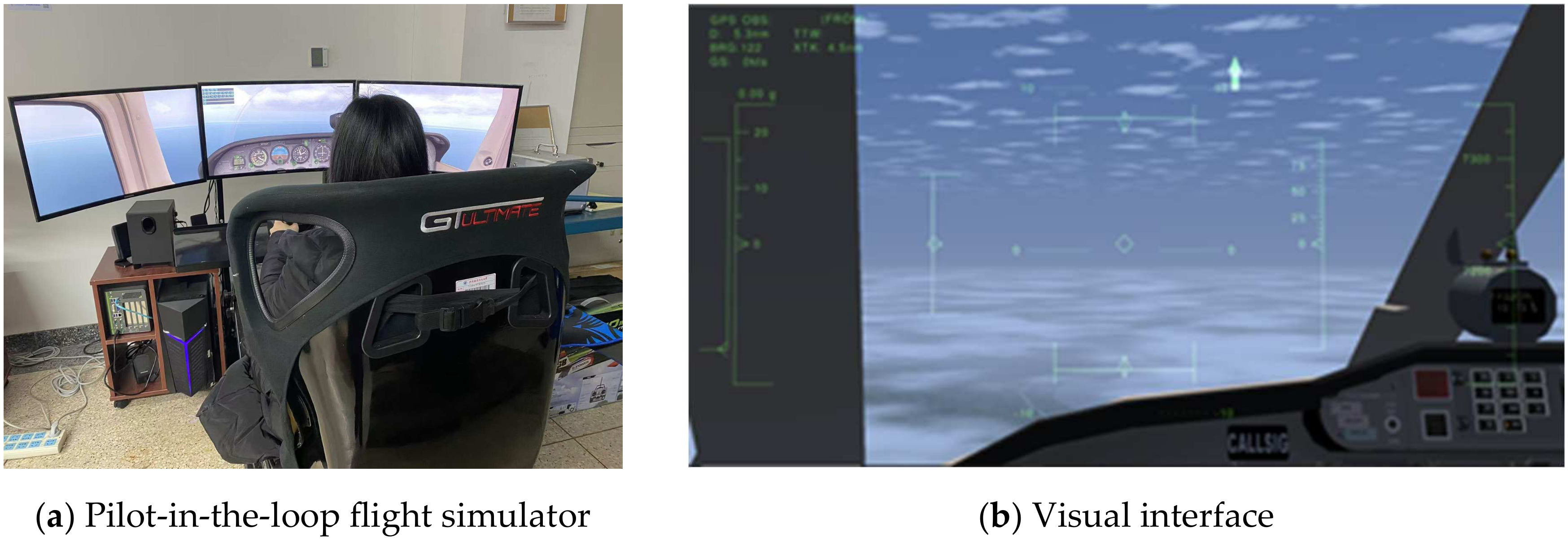
4.1. Human-in-the-Loop Simulation Experiment Design

The human-in-the-loop flight simulation experiment involves a pilot-aircraft system consisting of the pilot, the aircraft model, and the pilot-aircraft interface (including the display system and control stick, etc.). This system is a semi-physical simulation, as shown in Figure 8. The control stick is an active side stick equipped with a human sensing system, while the display system shows the current flight scenario and the aircraft’s flight status information. The aircraft model is a mathematical model built in MATLAB/Simulink 2022b, capable of real-time calculations.
The flight simulator control panel and visual scene in shown in Figure 9. First, the RT-LAB real-time simulation system is applied on the flight simulator, with the aircraft system model built using MATLAB/Simulink. Once the model is successfully constructed and running, the experiment begins. The pilot inputs control signals via the control stick, which are then sent to the simulator’s computer. The computer calculates the flight package, and the resulting flight state changes are displayed on the instruments for the pilot. Based on this information, the pilot makes judgments and issues control commands to complete the control task.

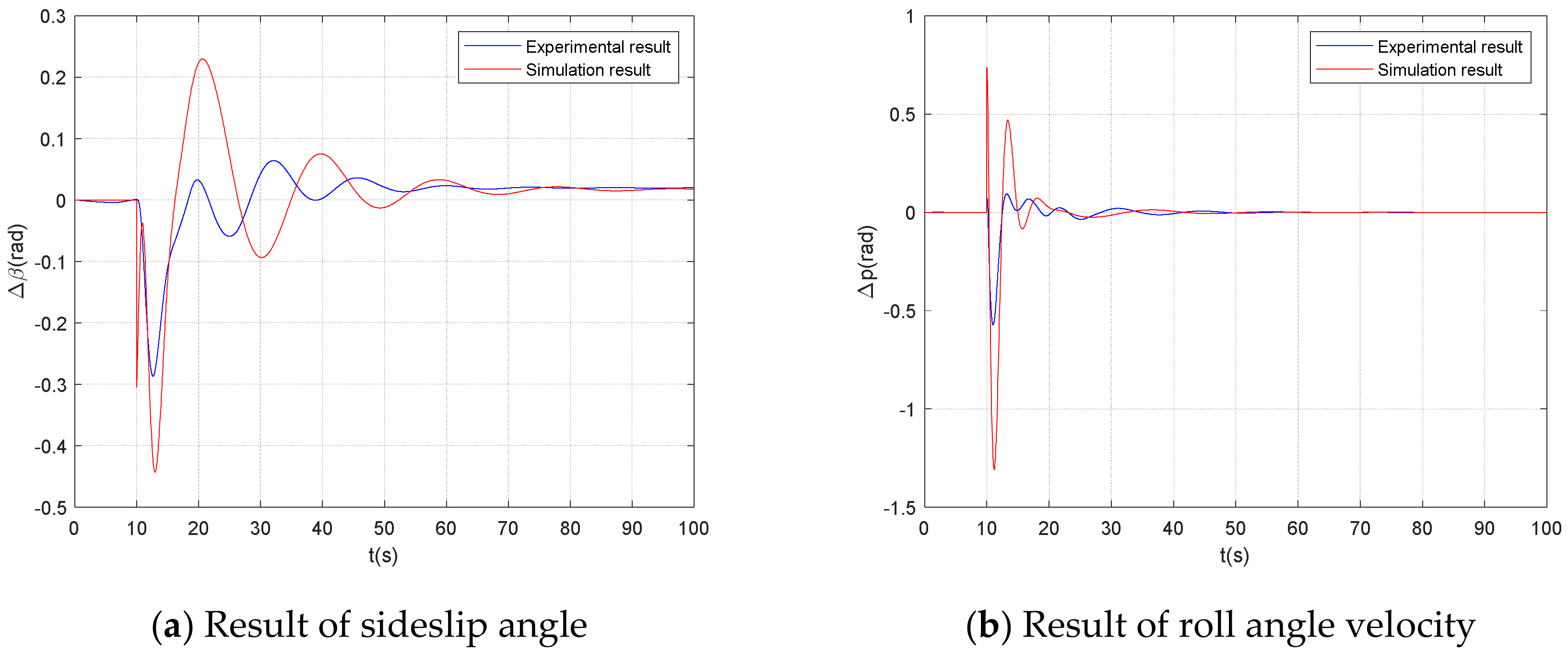
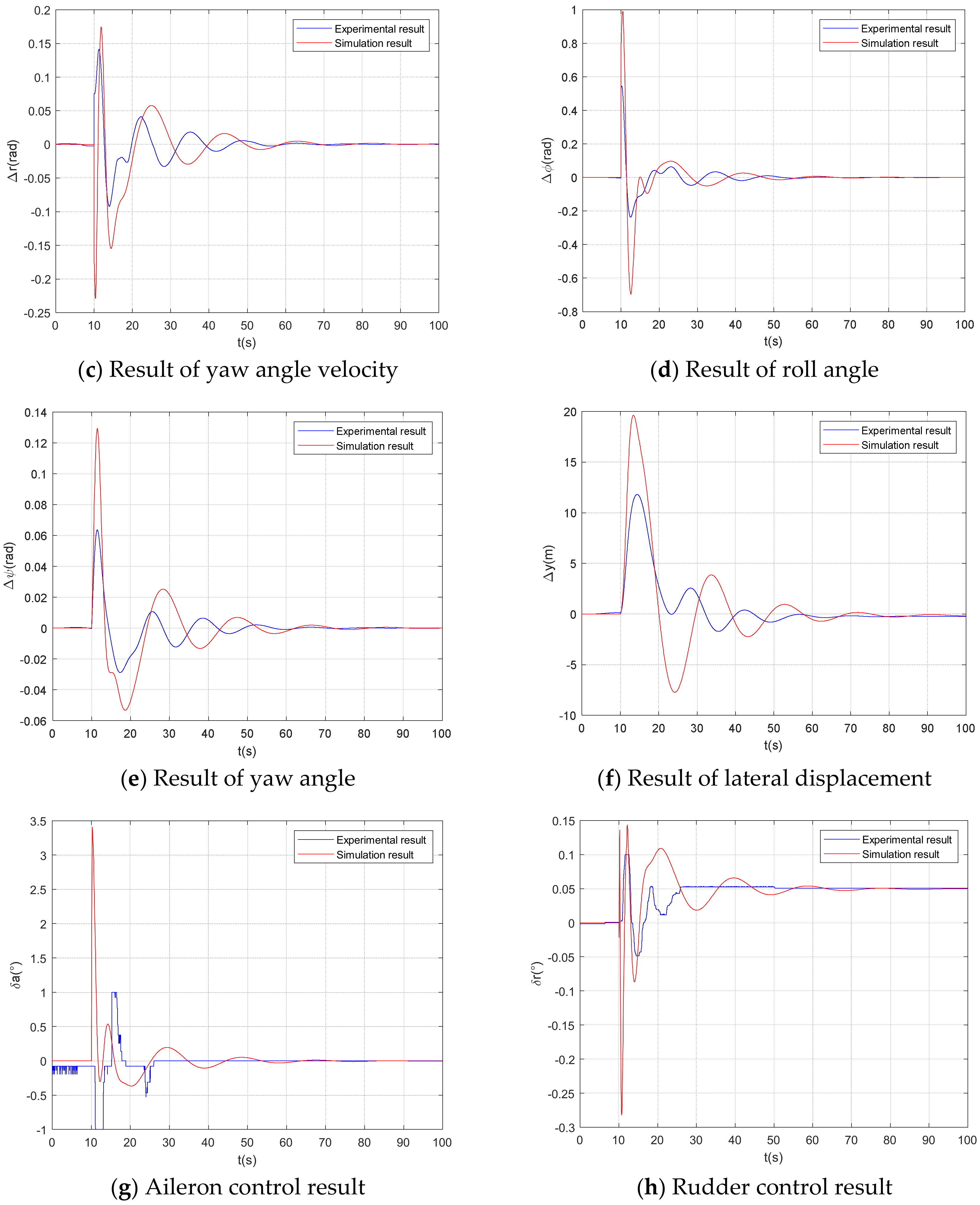
4.2. Experimental Results and Analysis

To validate the effectiveness of the proposed time-varying control strategy under asymmetric thrust, a comparative analysis was conducted between the results from the pilot model and those from the human-in-the-loop flight simulation experiment. The time-domain results are as follows. The aircraft’s flight status is shown in Figure 10a–f. It can be observed that after the engine failure, the aircraft’s sideslip angle, roll angle, yaw angle, roll rate, yaw rate, and lateral displacement all undergo changes, eventually stabilizing. Compared to the simulation, the experimental results are smoother, with smaller fluctuations and greater delay. This is due to the limited control input range in the experiment and the physiological response delays inherent in human pilots. Future improvements to the model will take factors, such as displacement limits and response delays, into account. However, the trends in the changes in flight parameters in both the experimental and simulated results are generally consistent.
The control results for the ailerons and rudder are shown in Figure 7g,h. It can be seen that the control frequencies in both the simulation and experiment align closely. Due to the limited control force in the experiment, the control fluctuation range in the simulation is slightly larger. Nonetheless, both methods successfully maintain stable flight.

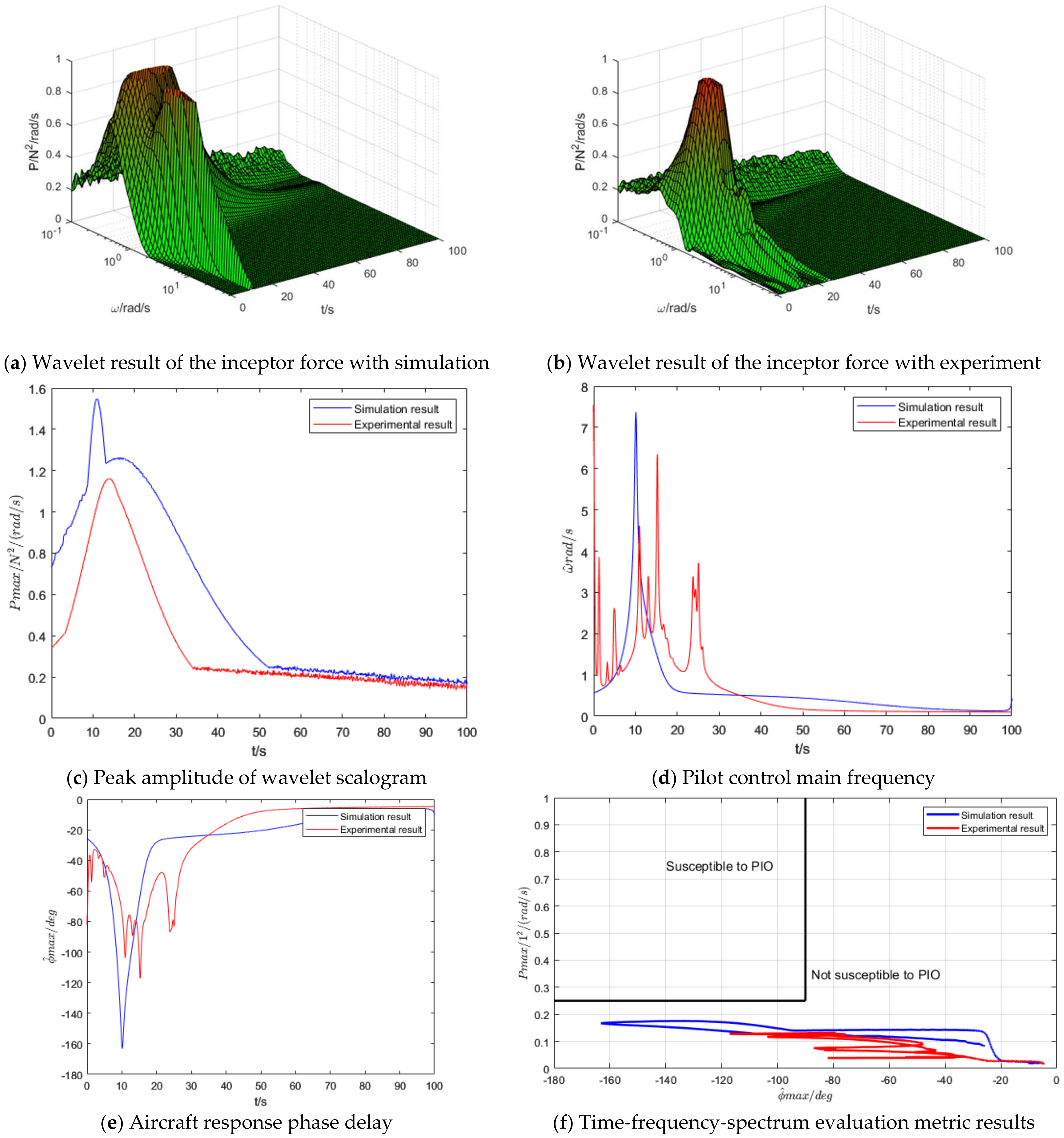
4.3. Aircraft-Pilot Couplings Evaluation Results

To further validate the established model, an analysis was conducted using the aircraft-pilot couplings evaluation method based on wavelet analysis [22]. The analysis focused on the time-varying spectral criteria, including the peak force spectrum, the pilot’s main frequency, and the phase delay at the main frequency. The results are as follows.
The evaluation results for the rudder control channel are presented in Figure 11. The wavelet analysis of the control force (Figure 11a,b) shows that the peak frequency spectra of the control force in both the experiment and the simulation are of similar magnitudes, with the peaks occurring at roughly the same times. The larger the peak, the more the result tends to red. The control force spectrum peak (Figure 11c) indicates that the peak frequencies in both the model and experimental results are quite comparable. Regarding the pilot’s control frequency (Figure 11d) and the corresponding phase delay in the aircraft’s response at the peak frequency (Figure 11e), while there is a difference in the peak values of the control frequency and phase delay, the timing of these peaks is consistent. This difference arises because, in the simulation, the pilot makes an instantaneous decision when detecting the failure. Whereas in the experiment, there is a physiological response delay. The time-varying spectral evaluation results (Figure 11f) reveal that the trends in both the experimental and simulation results align closely. Due to the influence of the main frequency, the model exhibits a slightly greater phase lag, but in both cases, the system remains within a range where pilot-induced oscillations (PIO) are unlikely to occur.
The evaluation results for the aileron control channel are shown in Figure 12. The wavelet analysis of the control force (Figure 12a,b) indicates that the control force spectra obtained from both the experiment and the model simulation are fairly consistent in magnitude, with similar peak times and frequencies. From the control force spectrum peak (Figure 12c), it can be seen that the experimental results are slightly lower than the model’s, which is due to the limitation of the control force amplitude, resulting in a smaller peak value in the experiment. Regarding the pilot’s control frequency (Figure 12d) and the corresponding phase delay in the aircraft’s response at the peak frequency (Figure 12e), it is observed that the peak values of both the control frequency and phase delay are quite close, although some fluctuation is present in the experimental results, whereas the simulation results are relatively smooth. The time-varying spectral evaluation results (Figure 12f) show that both the experimental and simulation results fall within the range unlikely to lead to PIO (pilot-induced oscillations), with trends that are generally consistent. This verifies the effectiveness of the proposed time-varying control strategy.

5. Conclusions

This paper addresses the issue of changes in flight characteristics caused by single-engine failure and proposes a time-varying control strategy for pilot operation of a multi-engines aircraft with asymmetric thrust. A time-varying pilot-aircraft system control model for single-engine failure is established, and the model is validated through pilot-in-the-loop flight simulation experiments. The following conclusions are drawn:
(1)
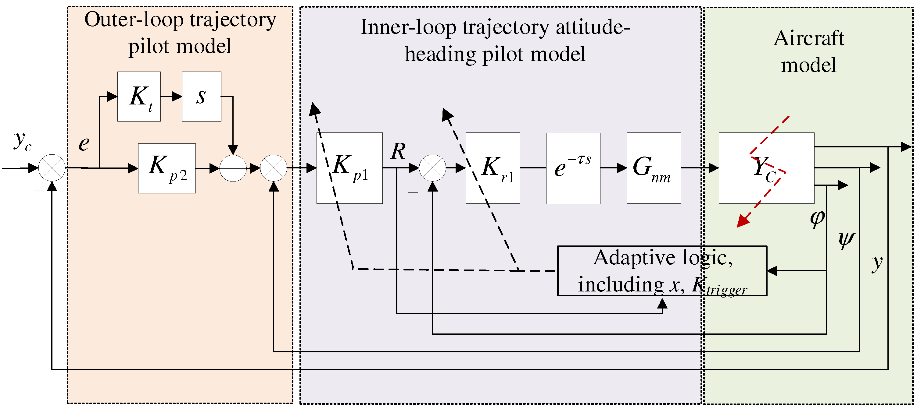
A multi-loop control behavior model for the pilot is developed, which includes the inner-loop attitude-heading control and outer-loop trajectory control under aileron manipulation, as well as command sideslip control under rudder manipulation. This model fully describes the pilot’s control behavior under asymmetric thrust, accounting for the resulting lateral-directional imbalance and strong coupling.
(2)
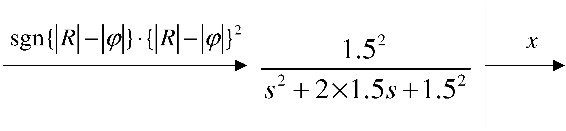
Considering the pilot’s time-varying and adaptive response to failure, the model integrates the pilot’s control demands under asymmetric thrust and extends the Hess time-varying pilot model in both structure and form. Based on this, a time-varying lateral-directional control strategy model for the pilot is established. Pilot-aircraft system simulation results show that this model maintains flight stability after a failure occurs.
(3)
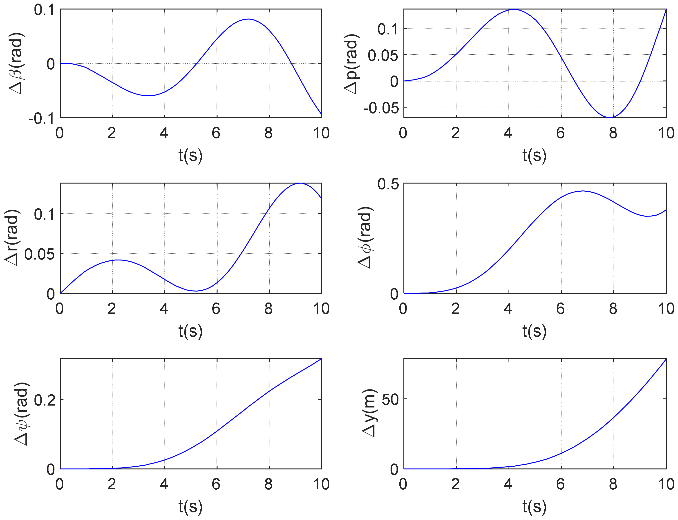
Comparing the pilot-in-the-loop simulation results with the experimental data, the time-domain analysis indicates that the experimental and simulation results for the aircraft’s flight state are in good agreement. The time-varying aircraft-pilot coupling evaluation shows that both the experimental and simulation results fall within a range where pilot-induced oscillations are unlikely to occur, and their trends are consistent. This verifies the effectiveness of the proposed strategy model.
(4)
The human pilot model developed herein needs further investigation. (a) Some machine learning components will be built into the control scheme to make the control more realistic. (b) More experiments and models will be extended to address more issues, e.g., dual-engine failure, challenging weather conditions, etc.

Author Contributions

Conceptualization, S.X. and Z.Z.; methodology, S.X.; software, S.X.; validation, S.X.; formal analysis, S.X.; investigation, S.X.; resources, Z.Z.; data curation, Z.Z.; writing—original draft preparation, S.X.; writing—review and editing, Z.Z.; visualization, Z.Z.; supervision, Z.Z.; project administration, S.X.; funding acquisition, S.X. All authors have read and agreed to the published version of the manuscript.

Funding

The study is supported by the National Natural Science Foundation of China, grant No. 12402413 and No. 52302464.

Data Availability Statement

The original contributions presented in this study are included in the article. Further inquiries can be directed to the corresponding author.

Conflicts of Interest

The authors declare no conflicts of interest.

References

  1. Xu, J.; Wang, Y.; Wang, Z.; Wang, X.; Zhao, Y. Transient gas path fault diagnosis of aero-engine based on domain adaptive offline reinforcement learning. Aerosp. Sci. Technol. 2024, 155, 109701. [Google Scholar] [CrossRef]
  2. Parnell, K.J.; Wynne, R.A.; Griffin, T.G.C.; Plant, K.L.; Stanton, N.A. Generating design requirements for flight deck applications: Applying the perceptual cycle model to engine failures on take-off. Int. J. Hum. Comput. Interact. 2021, 37, 611–629. [Google Scholar] [CrossRef]
  3. Neves, G.F.; de Souza, R.F.; Titton, C.C.; Messias, G.E.; Cruz, L.R. Wing aerodynamic loading asymmetry in engine failure condition for multi-propeller driven airplanes. In Proceedings of the AIAA SCITECH 2023 Forum, Online, 23–27 January 2023; p. 0219. [Google Scholar]
  4. Huang, Y.; Sun, G.; Tao, J.; Hu, Y.; Yuan, L. A modified fusion model-based/data-driven model for sensor fault diagnosis and performance degradation estimation of aero-engine. Meas. Sci. Technol. 2022, 33, 085105. [Google Scholar] [CrossRef]
  5. Wang, T.; Noori, M.; Altabey, W.A.; Wu, Z.; Ghiasi, R.; Kuok, S.C.; Silik, A.; Farhan, N.S.; Sarhosis, V.; Farsangi, E.N. From model-driven to data-driven: A review of hysteresis modeling in structural and mechanical systems. Mech. Syst. Signal Process. 2023, 204, 110785. [Google Scholar] [CrossRef]
  6. Chen, X.; Tong, Z.; Liu, Y.; Wang, Y.; Qing, X. A hybrid multi-model-based condition monitoring and sensor fault detection method for aero gas turbine. IEEE Sens. J. 2024, 24, 32729–32739. [Google Scholar] [CrossRef]
  7. Huang, Y.; Tao, J.; Zhao, J.; Sun, G.; Yin, K.; Zhai, J. Graph structure embedded with physical constraints-based information fusion network for interpretable fault diagnosis of aero-engine. Energy 2023, 283, 129120. [Google Scholar] [CrossRef]
  8. Parnell, K.J.; Banks, V.A.; Plant, K.L.; Griffin, T.G.; Beecroft, P.; Stanton, N.A. Predicting design-induced error on the flight deck: An aircraft engine oil leak scenario. Hum. Factors 2021, 63, 938–955. [Google Scholar] [CrossRef] [PubMed]
  9. Kordt, M.; Ackermann, J. Robust synergetic design of structural dynamic engine out controllers in parameter space. J. Guid. Control Dyn. 2001, 24, 305–314. [Google Scholar] [CrossRef]
  10. Zhou, X.; Huang, J.; Lu, F.; Zhou, W.; Liu, P. A novel compound fault-tolerant method based on online sequential extreme learning machine with cycle reservoir for turbofan engine direct thrust control. Aerosp. Sci. Technol. 2023, 132, 108059. [Google Scholar] [CrossRef]
  11. Liu, Y.; Tao, G.; Joshi, S.M. Modeling and model reference adaptive control of aircraft with asymmetric damage. J. Guid. Control Dyn. 2010, 33, 1500–1517. [Google Scholar] [CrossRef]
  12. Lian, G.; Chen, J.; Fan, Z.; Sun, C. Research on the Influence Factors of Ground Minimum Control Speed of Civil Aircraft Based on Dynamic Simulation. In Proceedings of the 2024 3rd International Symposium on Aerospace Engineering and Systems (ISAES), Nanjing, China, 22–24 March 2024; IEEE: Piscataway, NJ, USA, 2024; pp. 312–317. [Google Scholar]
  13. Etherington, T.J.; Kramer, L.J.; Kennedy, K.D.; Bailey, R.E.; Last, M.C. Quantifying pilot contribution to flight safety during dual generator failure. In Proceedings of the 2017 IEEE/AIAA 36th Digital Avionics Systems Conference (DASC), St. Petersburg, FL, USA, 17–21 September 2017; IEEE: Piscataway, NJ, USA, 2017. [Google Scholar]
  14. Hariowibowo, H.; Arifianto, O.; Pasaribu, H.M.; Muhammad, H. Fighter Aircraft Closed Loop Handling Quality Simulation on Lateral-Directional Modes. J. Aeronaut. Astronaut. Aviat. 2021, 53, 129–135. [Google Scholar]
  15. Hess, R.A. Modeling Pilot Control Behavior with Sudden Changes in Vehicle Dynamics. J. Aircr. 2009, 46, 1584–1592. [Google Scholar] [CrossRef]
  16. Hess, R.A. Modeling Human Pilot Adaptation to Flight Control Anomalies and Changing Task Demands. J. Guid. Control Dyn. 2016, 39, 655–666. [Google Scholar] [CrossRef]
  17. Xu, S.; Wu, Y. Modeling multi-loop intelligent pilot control behavior for aircraft-pilot couplings analysis. Aerosp. Sci. Technol. 2021, 112, 106651. [Google Scholar] [CrossRef]
  18. Hess, R.A. Modeling the pilot detection of time-varying aircraft dynamics. J. Aircr. 2012, 49, 2100–2104. [Google Scholar] [CrossRef]
  19. Lu, L.; Jump, M. Multiloop pilot model for boundary-triggered pilot-induced oscillation investigations. J. Guid. Control Dyn. 2014, 37, 1863–1879. [Google Scholar] [CrossRef]
  20. Xu, S.T.; Tan, W.Q.; Wang, W.J.; Sun, L. Pilot time-varying control behavior modeling in refractory period with aircraft failures. Sci. China Technol. Sci. 2023, 66, 2000–2012. [Google Scholar] [CrossRef]
  21. Wang, L.; Zhu, Q.; Zhang, Z.; Dong, R. Modeling pilot behaviors based on discrete-time series during carrier-based aircraft landing. J. Aircr. 2016, 53, 1922–1931. [Google Scholar] [CrossRef]
  22. Xu, S.T.; Tan, W.Q.; Qu, X.J. Prediction of nonlinear pilot-induced oscillation using an intelligent human pilot model. Chin. J. Aeronaut. 2019, 32, 2592–2611. [Google Scholar] [CrossRef]
  23. Hess, R.A. Unified theory for aircraft handling qualities and adverse aircraft-pilot coupling. J. Guid. Control Dyn. 1997, 20, 1141–1148. [Google Scholar] [CrossRef]
  24. Ji, M. Research on Control Law Reconfiguration for Civil Aircraft with Asymmetric Thrust. Master’s Thesis, Nanjing University of Aeronautics and Astronautics, Nanjing, China, 2011; pp. 31–34. [Google Scholar]
Figure 1. Asymmetric thrust pilot multi-loop and multi-channel control structure.
Actuators 14 00222 g001
Figure 2. Hess simplified loop-by-loop pilot model reproduced from [15].
Actuators 14 00222 g002
Figure 3. Pilot aileron control model under asymmetric thrust.
Actuators 14 00222 g003
Figure 4. Time-varying model form of pilot aileron control under asymmetric thrust.
Actuators 14 00222 g004
Figure 5. Definition variable x block diagram.
Actuators 14 00222 g005
Figure 6. Lateral response of aircraft under asymmetric thrust.
Actuators 14 00222 g006
Figure 7. Simulation results.
Actuators 14 00222 g007aActuators 14 00222 g007b
Figure 8. Composition of human-vehicle system for simulating human-in-the-loop.
Actuators 14 00222 g008
Figure 9. Flight simulator and visual interface.
Actuators 14 00222 g009
Figure 10. Comparison between experimental and simulation results.
Actuators 14 00222 g010aActuators 14 00222 g010b
Figure 11. Evaluation results of rudder control.
Actuators 14 00222 g011
Figure 12. Evaluation results of aileron control.
Actuators 14 00222 g012
Disclaimer/Publisher’s Note: The statements, opinions and data contained in all publications are solely those of the individual author(s) and contributor(s) and not of MDPI and/or the editor(s). MDPI and/or the editor(s) disclaim responsibility for any injury to people or property resulting from any ideas, methods, instructions or products referred to in the content.

