Article

Design of High-Speed Motor System for EV Based on 1200 V SiC-MOSFET Power Module

1
State Key Laboratory of Precision Manufacturing for Extreme Service Performance, College of Mechanical and Electrical Engineering, Central South University, Changsha 410017, China
2
Dongfeng Motor Corporation, Wuhan 430056, China
*
Authors to whom correspondence should be addressed.
Actuators 2025, 14(5), 216; https://doi.org/10.3390/act14050216
Submission received: 24 February 2025 / Revised: 11 April 2025 / Accepted: 15 April 2025 / Published: 26 April 2025
(This article belongs to the Special Issue Power Electronics and Actuators—Second Edition)

Abstract

:
In this paper, a high-speed motor system for an Electric Vehicle (EV) is designed, of which the rated DC-link voltage is 800 V and peak power can reach 200 kW with a high-efficiency Silicon Carbide Metal Oxide Semiconductor Field Effect Transistor (SiC-MOSFET). With the help of optimization motor design methods, such as pole–slot combination optimization, process optimization and control optimization, the motor can reach its maximal speed of 25,000 rpm and maximal torque of 240 Nm. Finally, the performance of the high-voltage motor system based on the SiC-MOSFET power module is evaluated by simulation and experiment.

1. Introduction

Compared with a 400 V voltage motor system, the 800 V high-voltage motor system has the advantage of a smaller current, so that the wiring harness volume can be reduced and the circuit resistance losses are decreased, by which the power density and efficiency of the system are improved. On the other hand, the 800 V high-voltage system can greatly speed up charging performance.
Compared with the Insulated Gate Bipolar Transistor (IGBT), SiC-MOSFET has the characteristics of high voltage, high frequency, and low loss, which is suitable for a high-voltage system. The system based on the SiC-MOSFET power module schematic diagram is shown in Figure 1.
The losses of IGBT and SiC-MOSFET used in the EV controller were compared and analyzed [1], and compared to IGBT, the conduction loss and switching loss of SiC-MOSFET are reduced by 60% at most. The analysis shows that the maximum junction temperatures and junction temperature fluctuations of SiC-MOSFET are much lower than IGBT under all tested conditions [2]. The loss of the inverter is reduced and the range of EV is increased by 5% when SiC-MOSFET is used and voltage is increased [3,4]. With the usage of SiC-MOSFET and SiC-SBD (Silicon Carbide Schottky Barrier Diode), the motor drive system enjoys superior performance of 0–12,000 rpm, maximum power of 65 kW and maximum efficiency of more than 95% through a combination with winding conversion technology [5]. The application of SiC-MOSFET in EV is applied with a nonlinear loss calculation model of PMSM [6]. The application considered the matching problems of a motor and a semiconductor device and optimized the design of the Halbach-Rotor PMSM [7,8]; after optimization, the efficiency, torque ripple and power density were improved. Both the PMSM and SRM (Switched Reluctance Motor) are compared by FEA (Finite Element Analysis) under the same power of 85 kW, and the comparison results show that PMSM has a higher efficiency in the speed range from 4000 rpm to 30,000 rpm [9]. By studying the relationships among radial force, torque ripple, and airgap flux density, establishing the centrifugal force model of the magnetic pole, reference [10] analyzed the electromagnetic vibration and mechanical stress characteristics of the motor and optimized the vibration and mechanical stress area simultaneously. Four rotor structures of the high-speed IPM motor are analyzed and compared comprehensively. The results show that the PM segmented by stiffeners plus carbon fiber sleeve exhibits the best performance in terms of mechanical strength; however, manufacturing tolerances have a significant impact on it [11]. Reference [12] compared an improved triangle rotor topology with a V-shape rotor on air-gap, flux density, torque, inductance and the motor’s overall efficiency (et) by FEA, and the results proved that the new rotor topology has more advantages. Reference [13] proposed a 110 kW PMSM with a maximum speed of 13,300 rpm; while the efficiency could reach 96%, however, the electrical and mechanical designs are both challenged by high speeds. Considering parasitic parameters of hairpin windings, a high-frequency circuit model is proposed to analysis the voltage stress of EV traction machines driven by SiC-MOSFET; on the basis of this, a low interturn voltage stress design of a hairpin winding under a SiC voltage pulse is studied [14]. Using powering 400 V and 800 V 160 kW rated traction machines, all-SiC inverters, hybrid SiC inverters and IGBT inverters are studied by loss modeling, and the conclusions show that the 800 V bus and all-SiC inverter contributes to the highest efficiency, which results in a range increase of 5.0% compared to the 400 V IGBT [15]. Reference [16] analyzed the influence of parameters such as winding type, slot opening width and sleeve thickness on eddy current losses and represented an approach to minimize such losses. It is theoretically illustrated and experimentally demonstrated that the high switching frequency and fast switching speed of SiC-MOSFET increase the amplitude of the shaft voltage, which is studied by fast Fourier transform, and active zero state pulse width modulation is used to minimize the shaft voltage [17]. Reference [18] introduced a pole–slot combination selection of a motor. References [19,20] focus on new materials application on a high-speed motor. What is more, many scholars have conducted extensive research in the field of high-speed motor control [21,22], including sensorless control [23,24,25,26] and fault-tolerant control [27].
With the development of motor systems using high speeds and high voltages, the third-generation power semiconductor device SiC-MOSFET has been widely used due to its high working frequency and low switching loss advantages. Many scholars have done a lot of work in this field, but the research on the design of a whole motor system and the matching of a motor with an inverter is still relatively lacking. In this paper, the hardware and software design of a motor controller based on a SiC-MOSFET power module are introduced, and the electromagnetic performance of a high-speed motor is optimized. Finally, the performance of the whole system is evaluated by simulation and experiment.

2. Motor System Design

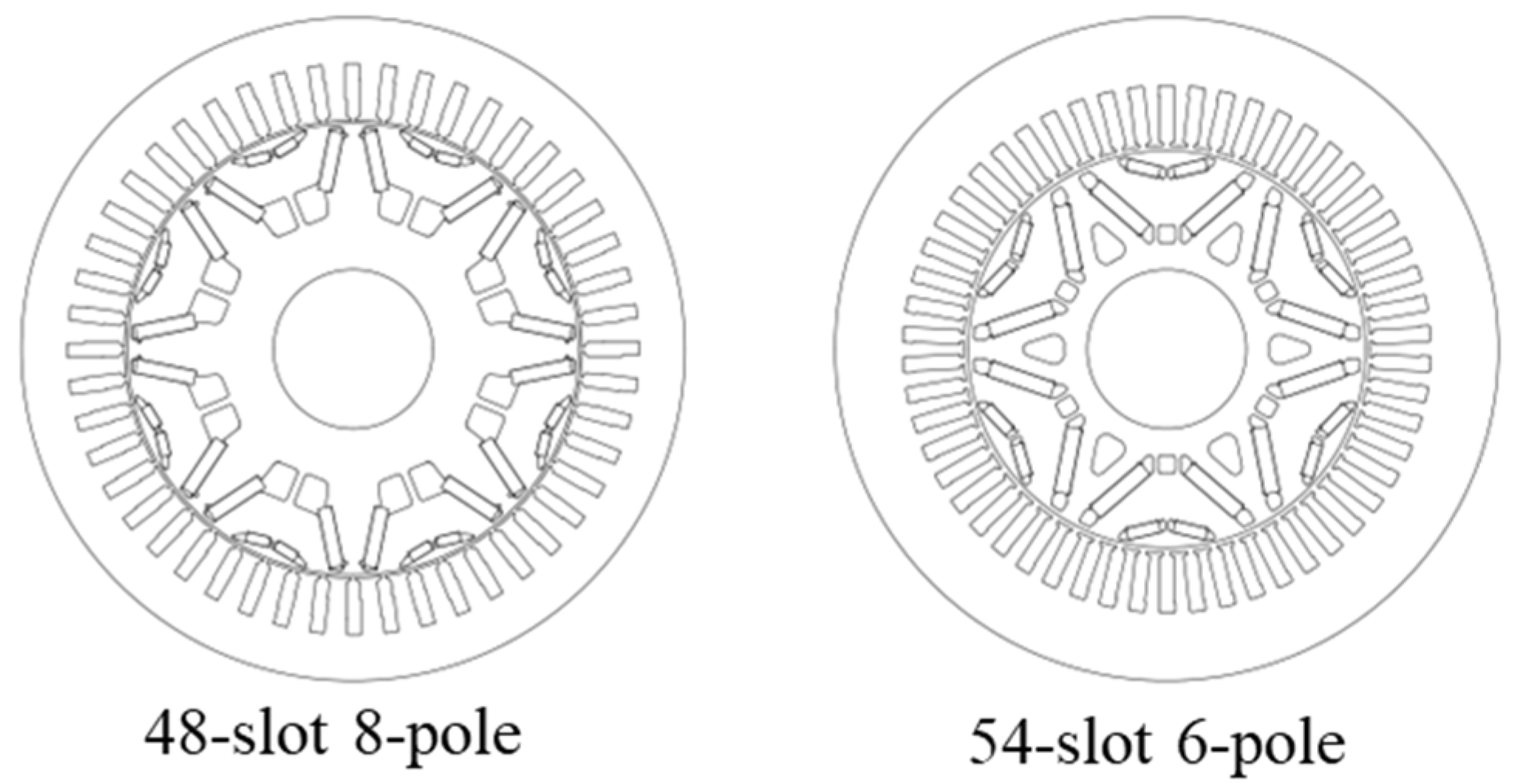
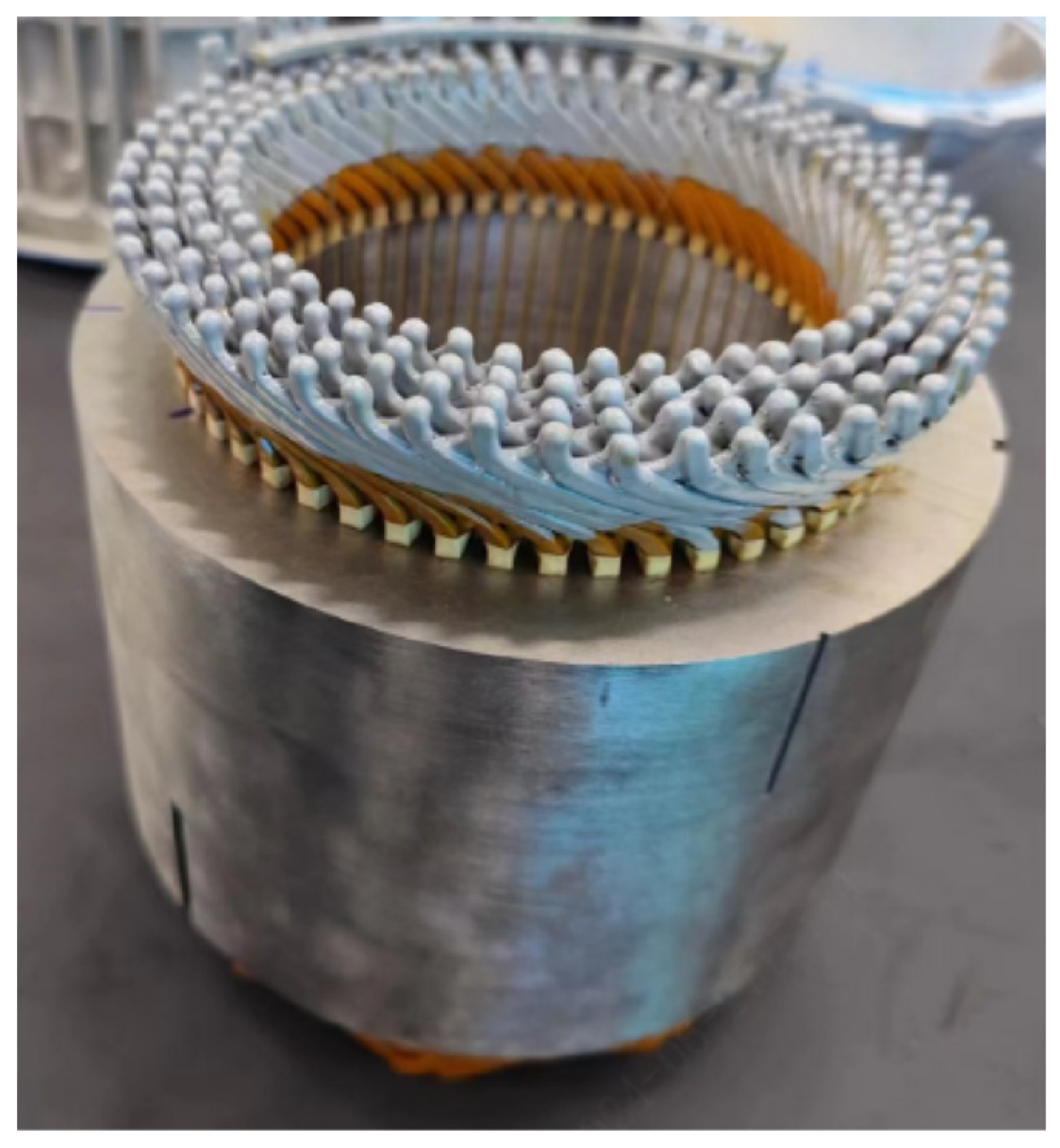
2.1. High-Speed Motor Design

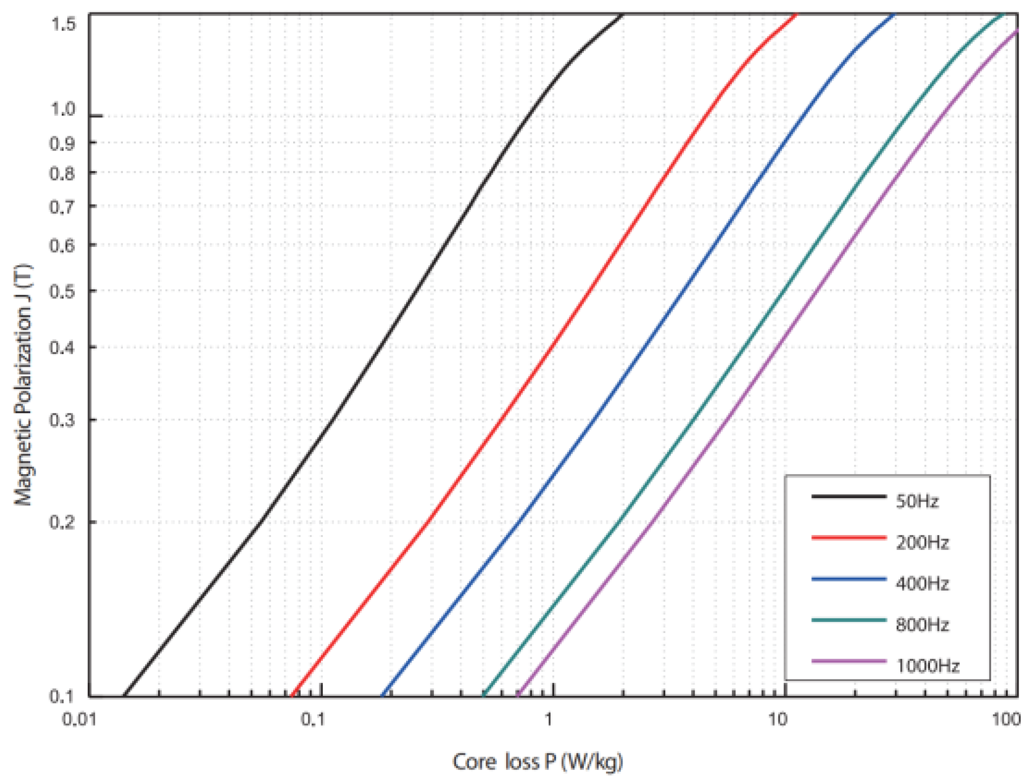
2.1.1. Iron Loss Optimization

Iron loss can be reduced by using thinner silicon steel sheets. The efficiency maps of motors using 0.3 mm and 0.2 mm silicon steel sheets are shown in Figure 2. At present, the silicon steel sheet commonly used is 0.25 mm. In this paper, the silicon steel 20SW1200 of the Shougang Group is selected for its low iron loss. The typical iron loss of it is 11 W/kg under the condition of 1.0 T and 400 Hz. This ultra-thin silicon steel is only 0.2 mm. The iron loss of 0.2 mm silicon steel is 85.7% that of 0.25 mm silicon steel and 71.9% that of 0.3 mm silicon steel, respectively, when the current frequency is 800 Hz.
Figure 3 shows the relationship between frequency and core loss. In addition, considering the positive correlation between iron losses and frequency, as is shown in Figure 4, this paper changes the traditional 48-slot 8-pole structure to a 54-slot 6-pole structure, which can reduce the frequency by 25% at the same speed.

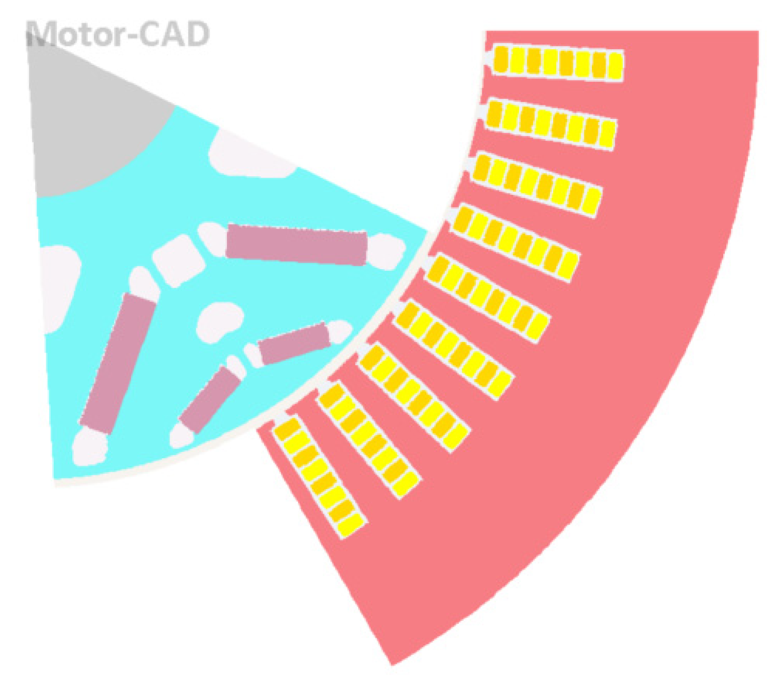
2.1.2. Copper Loss Optimization

As is shown in Figure 5, a double-V type magnetic pole is used to improve the reluctance torque. A large-aspect-ratio copper wire (3.565 mm × 1.635 mm) order dependence made by Sumitomo Corporation is used to weaken the skin effect. Furthermore, AC loss is reduced by optimizing the groove.

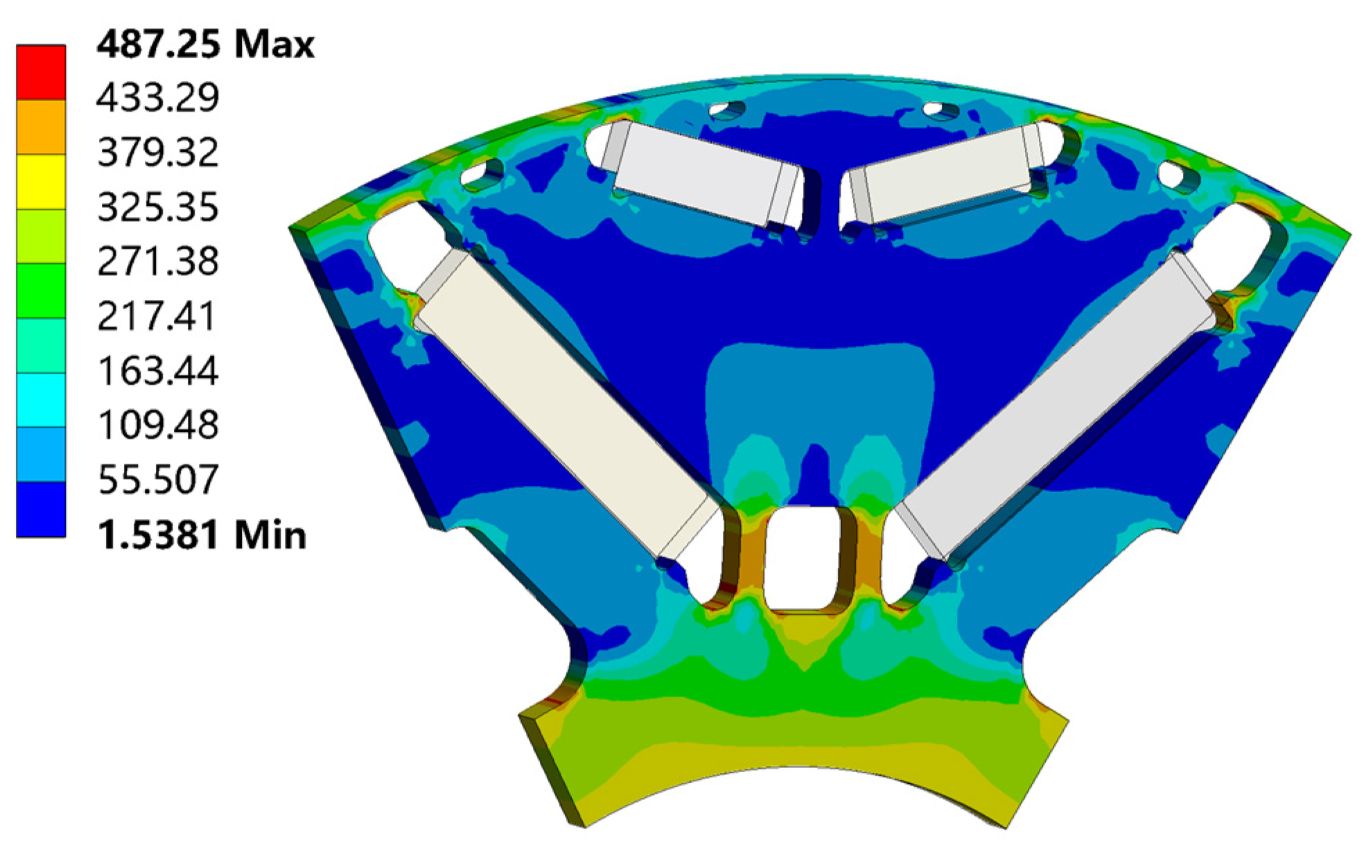
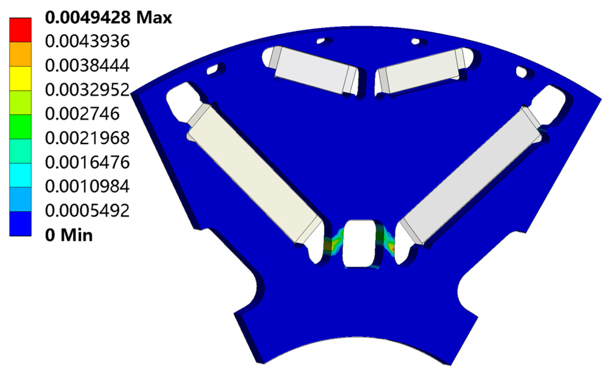
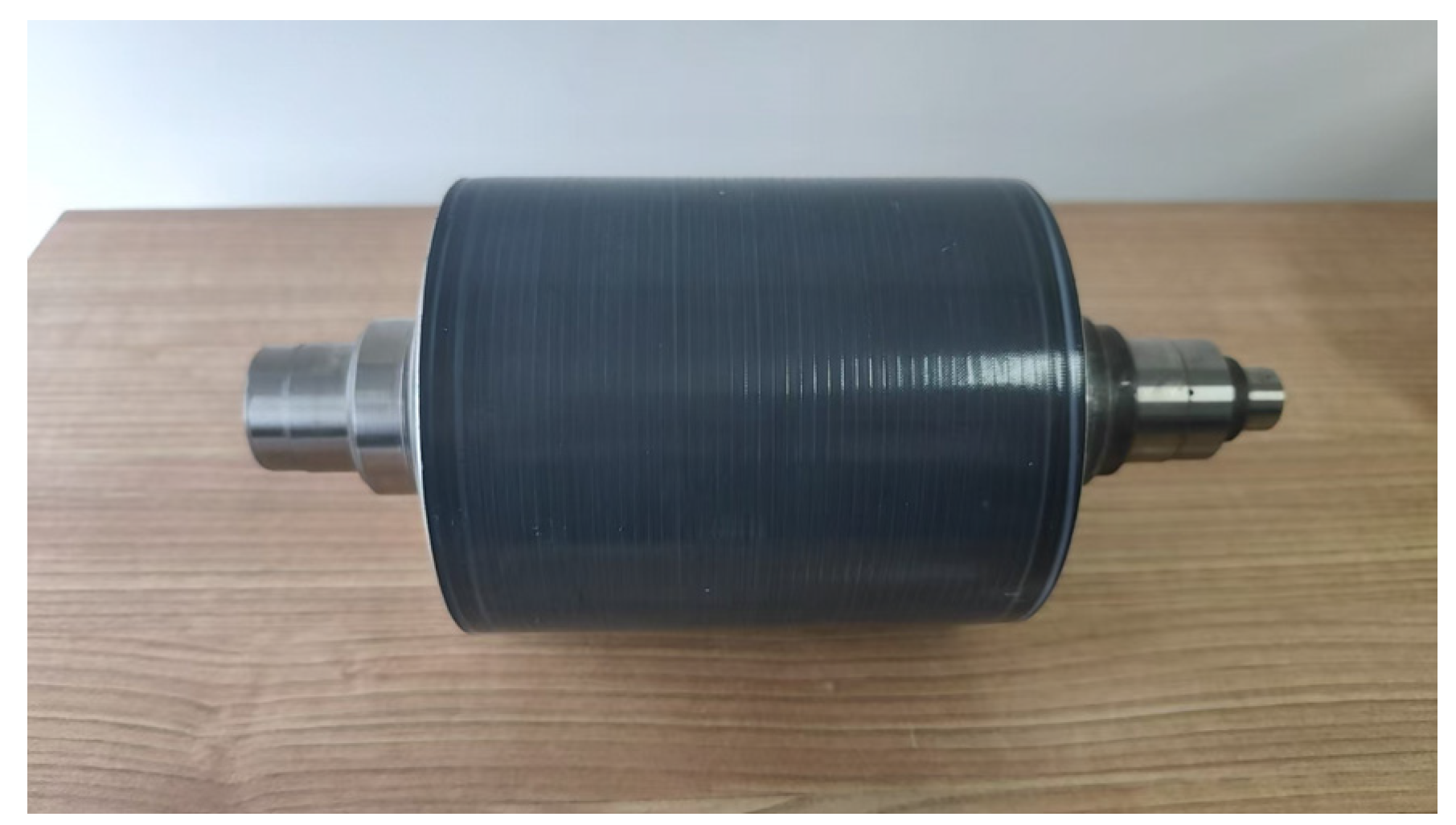
2.1.3. Structural Stress Optimization

A low-friction bearing model 6007 produced by the NTN company is used to reduce the loss of swing oil. In addition, segmented magnetic steel is used, and non-metallic coating is added to reduce the loss of magnetic steel.
Considering the difficulty of manufacturing 0.2 mm ultra-thin silicon steel, this paper uses a new process using an adhesive iron core, which can effectively avoid the influence of riveting on the magnetic field, damage to the material at the welding point, and the warpage of the iron core at the notch. Figure 6 shows the influence of different connection processes.
Considering the problem that the stress of a magnetic isolation bridge is large when the motor is running at high speed, the rules of stress and deformation changing with structural parameters are studied by analytical calculation and FEA. According to analysis, the structure of a double-V type rotor is optimized in which the thickness of the magnetic isolation bridge is reduced, and the electromagnetic performance of the motor is improved under the condition of strength requirements. In addition, this paper also reduces the maximum stress and deformation by reducing the angle of the pole shoe. As shown in Figure 7, the maximum mechanical stress of the rotor is 487.25 Mpa under the condition of overspeed by 1.2 times. As is shown in Figure 8, the maximum plastic strain is 0.49%, much lower than the 3% under the condition of overspeed by 1.2 times.
Under high-speed operating conditions, the centrifugal force of the rotor increases, posing significant challenges to the stability and safety of the motor. To address this issue, the rotor is typically wrapped in carbon fiber material. This paper uses the centroid equivalence principle to calculate centrifugal force at different rotational speeds, then equates the dynamic centrifugal force to a static concentrated load. The equivalent static concentrated force is then applied to the rotor’s axis of symmetry, and the strain is measured at the magnetic barrier bridge. The test bench and results using different thicknesses of carbon fiber are shown in Figure 9 and Table 1.
Through static tensile tests, it has been determined that the rotor with a 0.6 mm carbon fiber wrapping layer can meet the requirement for a maximum rotational speed of 25,000 rpm. However, to adapt to the complex conditions in vehicle applications, this paper ultimately opts a 0.8 mm carbon fiber model Toray T800S with a tensile strength of 2750 MPa in the 0° direction.

2.1.4. Main Parameters Calculation

The maximum output torque is 240 Nm, and the minimum DC bus voltage is 750 V. The torque is the sum of the permanent magnet torque and the reluctance torque, which is 240 Nm. The proportion of the two parts can be distributed. The proportion of reluctance torque is generally about 40–60% under rated working conditions. In order to reduce the amount of permanent magnet material, the ratio of reluctance torque is defined as 60% of output torque. As shown in Equation (1), T o u t is output torque; T m a g is permanent magnet torque; T r e l is reluctance torque.
T m a g = 0.4 T o u t = 96   Nm T r e l = 0.6 T o u t = 144   Nm
The peak value of phase current I p e a k which is determined by the basic parameters of the motor is 551 A. The range of the dq-axis current angle β is generally from 45° (knee point) to 65° (the maximum speed). The dq-axis current can be calculated as Equation (2) at breakover speed. (Using equal power transformation.)
i d = 3 2 × I p e a k sin β = 477   A i q = 3 2 × I p e a k cos β = 477   A
Since the motor has three pairs of poles, the permanent magnet flux linkage can be initially calculated as Equation (3), where ψ m a g is the permanent magnet flux linkage; P n is the number of motor pole pairs.
ψ m a g = T m a g P n i q = 67   mVs
According to the experience of electric vehicle motors, the saliency ratio is about 2.0~2.4. The dq-axis inductance of the motor can be calculated by Equation (4) when the saliency ratio of the motor is 2.2.
L d L q = T r e l P n i d i q = 211 uH L q L d = 2.2
From Equation (4), the dq-axis inductance can be calculated, as shown in Equation (5).
L d = 176   uH L q = 387   uH
The peak power is about 200 kW, from which the rated speed can be determined.
n = P p e a k 2 π T o u t × 60 = 8000   rpm
According to the above, the stator voltage can be calculated as follows.
V s t a t o r = ( ω L q i q + r i d ) 2 + ( ω ψ m a g + ω L q i q + r i q ) 2 = 450   V
In Equation (7), V s t a t o r is the stator voltage; ω is the electrical angular velocity of the motor at 8000 rpm; r is the phase resistance at 70 °C, which is about 30 mΩ according to simulation. Taking the dead time of switching and line voltage drop into account, the minimum DC bus voltage V o u t can be obtained.
V o u t = V s t a t o r 0.96 = 469   V
Since the DC-bus voltage is 750 V, the maximum voltage that the inverter can supply by SVPWM modulation is shown in Equation (9).
V s v p w m = 2 2 V d c min = 530   V
V s v p w m is the voltage in the two-phase stationary coordinate system. From Equation (9), DC-bus voltage can meet the requirements.
At the maximum speed (25,000 rpm, 20 °C), the higher the line-to-line back EMF is, the higher the maximum efficiency is. However, as shown in Table 2, the CLTC [28] efficiency increases first and then decreases according to the simulation analysis. In order to maximize CLTC efficiency, this paper finally choose 1109 V line-to-line back EMF at peak speed.
The above calculations provide a direction of high-speed motor design. Based on these calculation results and finite element analysis for further optimization, the main parameters of electromagnetic design of the high-speed motor are determined, as shown in Table 3.

2.2. Controller Design

2.2.1. SiC-MOSFET

In this paper, SiC-MOSFET, model ZM600FB12W3, produced by Dongfeng Motor Zhixin Semiconductor, Wuhan, China, is selected. The basic parameters of SiC-MOSFET are shown in Table 4.

2.2.2. Drive Circuit

The driving circuit is designed based on the GD3160 driver IC produced by the NXP semiconductor company (Eindhoven, The Netherlands). The driver IC supports a maximum PWM (Pulse-Width Modulation) of 100 kHz, is compatible with 200–1700 V IGBT or SiC-MOSFET, and operates at temperature between −40 °C and 125 °C, which can meet the needs of EV specification.
During the turn-on process of SiC-MOSFET, the small gate resistance may cause the gate loop to oscillate, and the larger resistance will increase the turn-on loss. As shown in Figure 10, the driving resistance in this paper uses four 27 Ω resistors in parallel, which is 6.75 Ω. In addition, in order to prevent the damage to the power device caused by the voltage in the main circuit when the gate circuit is not working, a protection circuit composed of a 10 kΩ resistor and a 22 nF capacitor is added between G and S.

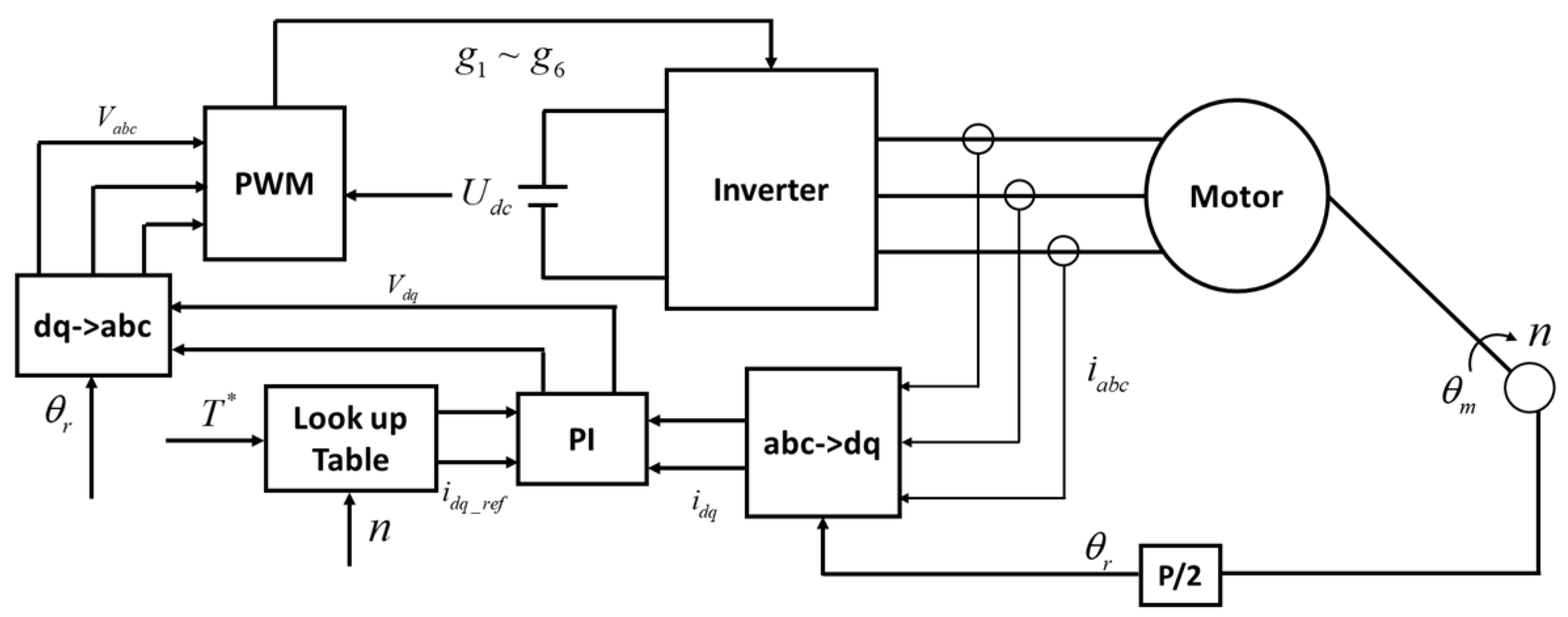
2.2.3. Control System

The overall control algorithm block diagram is shown in Figure 11. In this figure, the reference values of the dq-axis current are obtained by the command torque and current speed through a look-up table, the current PI controller is used to produce the voltage command, and the SVPWM is used to generate the signal of the switch tube.
Where g 1 ~ g 6 represent the six gate driving signals of the inverter; V a b c represents the three-phase voltage of the stator; U d c represents the DC-link voltage; i a b c represents the three-phase current of the stator; V d q represents the D-axis and Q-axis voltage of the stator; θ r is electrical angle and represents the location of the rotor; T * represents the reference torque; θ m is mechanical angle; n is speed of the motor; i d q is the D-axis and Q-axis current of the stator and i d q _ r e f is the reference current of the D-axis and Q-axis; and P represents the poles of the motor.
Among these elements, Renesas’s (Renesas, Kanagawa, Japan) RH850/C1M-A2 microcontroller is selected as system control CPU. This microcontroller is equipped with a dual-core CPU with a working frequency of 320 MHz for each core, which can control two motors in real time. Its computing power is among the best in the field of on-board motor controllers. The current sensor adopts NACA.900Q2-S5/SP1VA of CRRC (China Railway Rolling Stock Corporation, Beijing, China), which can realize current measurements from −900 A to 900 A. The bandwidth of this current sensor is 40 kHz, and the detection error is less than 0.5%. The high-precision DC voltage isolation sensor ACPL-C87 AT is used as DC-link voltage sensor, and the error of this sensor is between −0.5% and 0.5%. The resolver adopts 21VRX produced by MinebeaMitsumi, Tokyo, Japan. The output of this resolver is 0~4096, corresponding to a 360° electrical angle, working at −40 °C~150 °C, and the maximum speed of this resolver can reach 30,000 rpm.

3. Simulation and Experimental Analysis

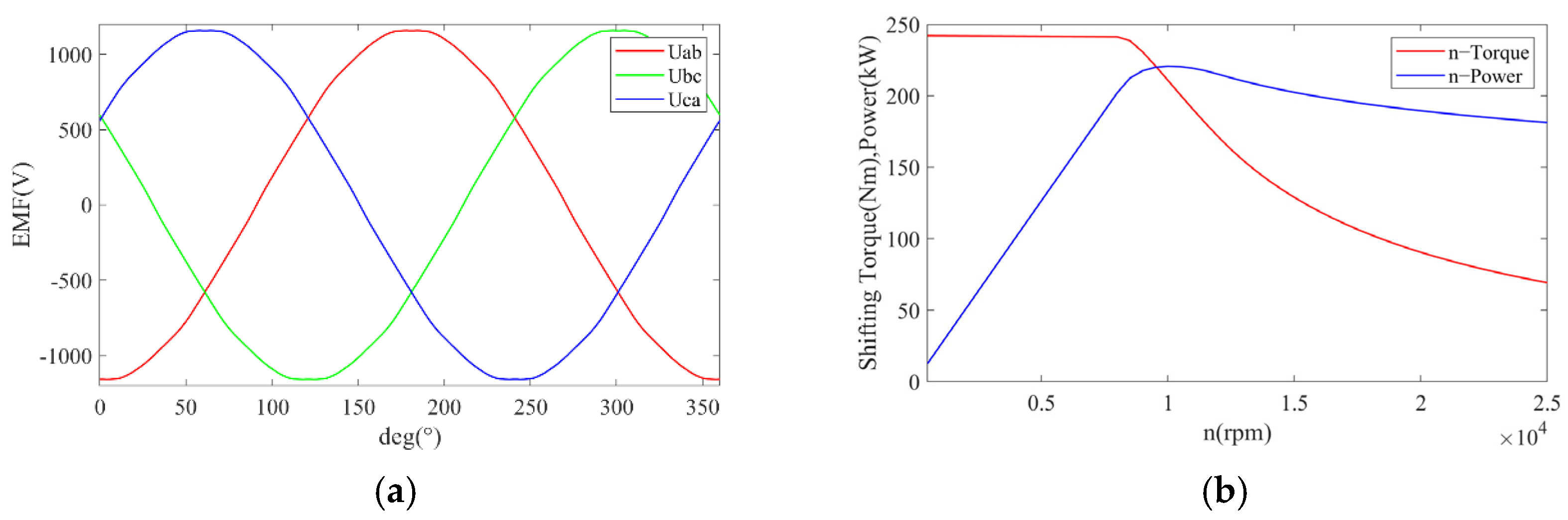
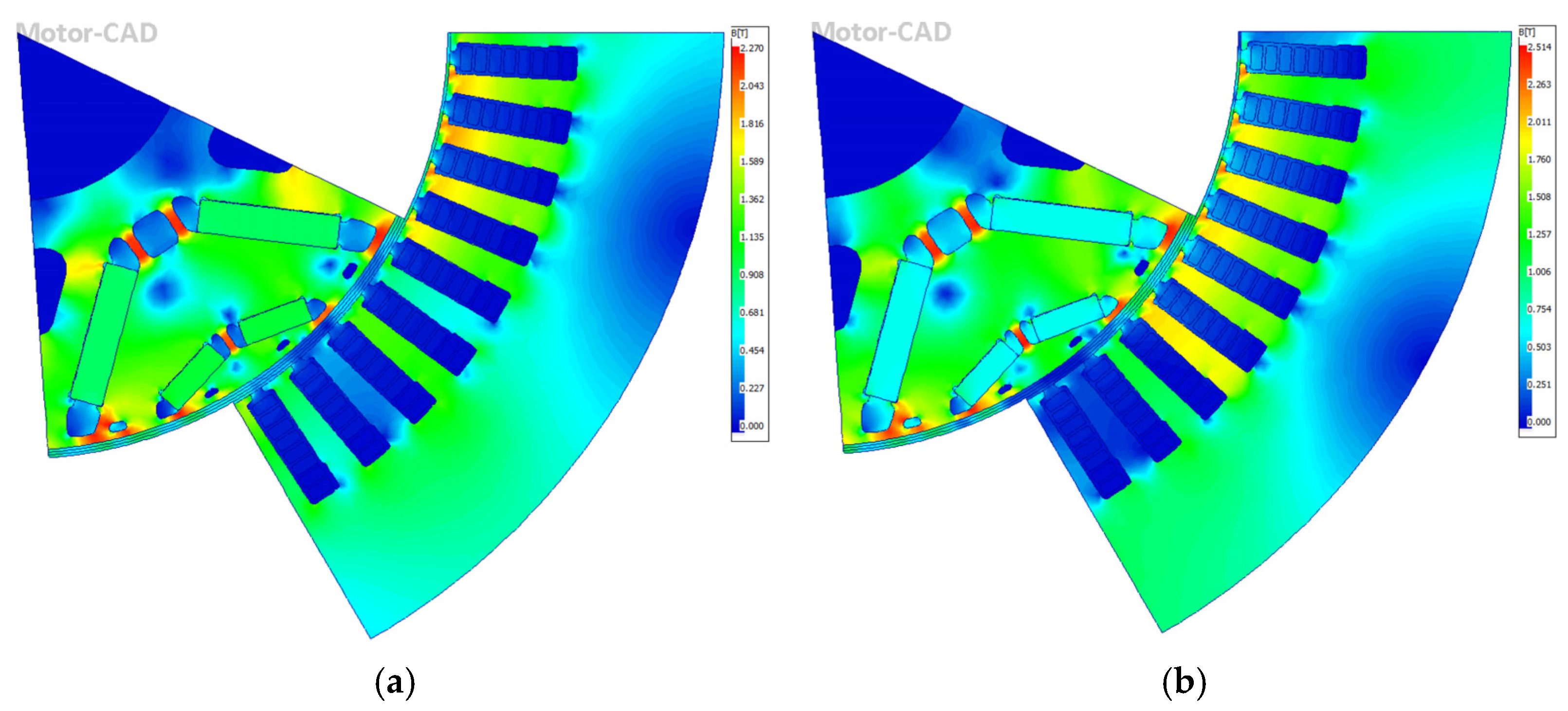
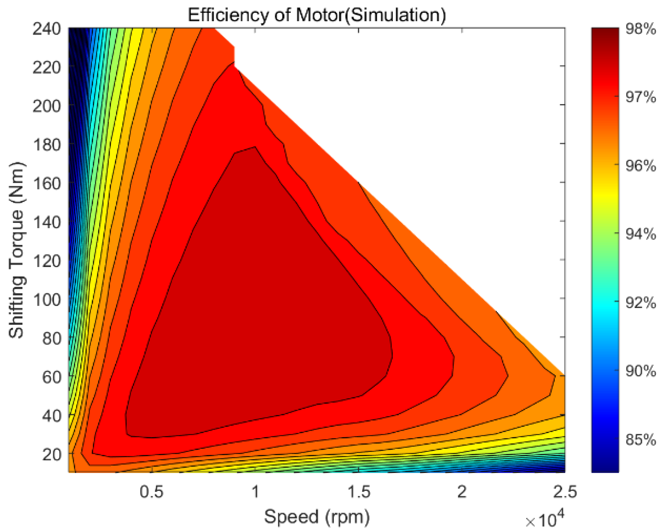
3.1. High-Speed Motor Simulation

The back EMF (Electromotive Force) and external characteristic curve of the motor are shown in Figure 12a. Under the condition that the speed is 25,000 rpm and the temperature is 20 °C, the peak line voltage of the proposed motor is 1169 V (rms); the maximum voltage harmonic component is less than 1% and the total harmonic distortion is less than 2%. In Figure 12b, the maximum output torque of the motor is 242 Nm. The maximum speed of the constant torque region is about 9000 rpm, and the maximum limited speed of the motor can reach 25,000 rpm under the safe operation. The maximum output power is 220.8 kW and the power at the maximum speed (25,000 rpm) is 181.3 kW.
The magnetic density of the motor is shown in Figure 13. Under rated conditions, the average air gap magnetic density is 0.584 T, the maximum magnetic density of the stator tooth is 1.682 T, and the maximum magnetic density of the rotor magnetic bridge is 2.27 T, as depicted in Figure 13a. Under the peak power condition, the average air gap magnetic density is 0.691 T, the maximum magnetic density of the stator tooth is 1.914 T, and the maximum magnetic density of the rotor magnetic bridge is 2.514 T, as described in Figure 13b. The high saturation of the rotor bridge magnetic density can reduce the magnetic leakage in this area. Under rated conditions, the magnetic density of the stator tooth is less than 1.7, close to saturation, which is conducive to controlling iron loss; and under peak conditions, the stator tooth flux density is saturated, which can maximize the use of silicon steel sheets and increase motor power.
The simulation of the motor peak torque is shown in Figure 14. The peak torque can reach 240 Nm. Under this working condition (8500 rpm, 240 Nm), the maximum torque is 244 Nm, the minimum torque is 238 Nm, and the pulsating torque is 1.67%.
The map of the quadrature axis current, direct axis current, copper loss, and iron loss under different working conditions is shown in Figure 15. From the figure, it can be seen that the q-axis current increases when the torque increases. Copper losses increase with power increasing, while iron loss is mainly related to the speed. In the constant power region, when the speed is the highest, the d-axis current is −291.5 A, and the q-axis current is 258.7 A. The maximum copper loss occurs at 11,000 rpm, 190 Nm, which is 7651 W. The maximum iron loss is 2181 W, which occurs at 24,000 rpm, 70 Nm.
The d-axis and q-axis inductances under different speeds and torques are shown in Figure 16. In this figure, the maximum d-axis inductance is 0.255 mH and the minimum is 0.179 mH. The maximum q-axis inductance is 0.6102 mH, and the minimum is 0.3892 mH. As load increases, the magnetic density increases, the magnetic steel saturation decreases, and the inductance decreases. When the speed is high, due to the field weakening control strategy, the magnetic steel is desaturated and the inductance increases, which is consistent with theoretical analysis.
The simulation map of permanent magnet flux linkage is shown in Figure 17. The permanent magnet flux linkage decreases with torque increasing, and the maximum flux linkage is about 106 mVs. With the saturation of the magnetic circuit, the maximum value of the flux linkage decreases to 84.7 mVs.
The simulation map of motor efficiency is shown in Figure 18. The highest efficiency of this proposed motor can reach 97.53%, and the efficiency area above 90% accounts for 91.92%. Under the peak power condition (8500 rpm, 240 Nm), the stator copper loss is 7616 W, the stator iron loss is 814.4 W, the rotor iron loss is 51.2 W, the magnetic loss is 8.5 W, the mechanical loss is 374 W, and the total losses are 8864 W. Thus, the efficiency of the motor is 96.02%.

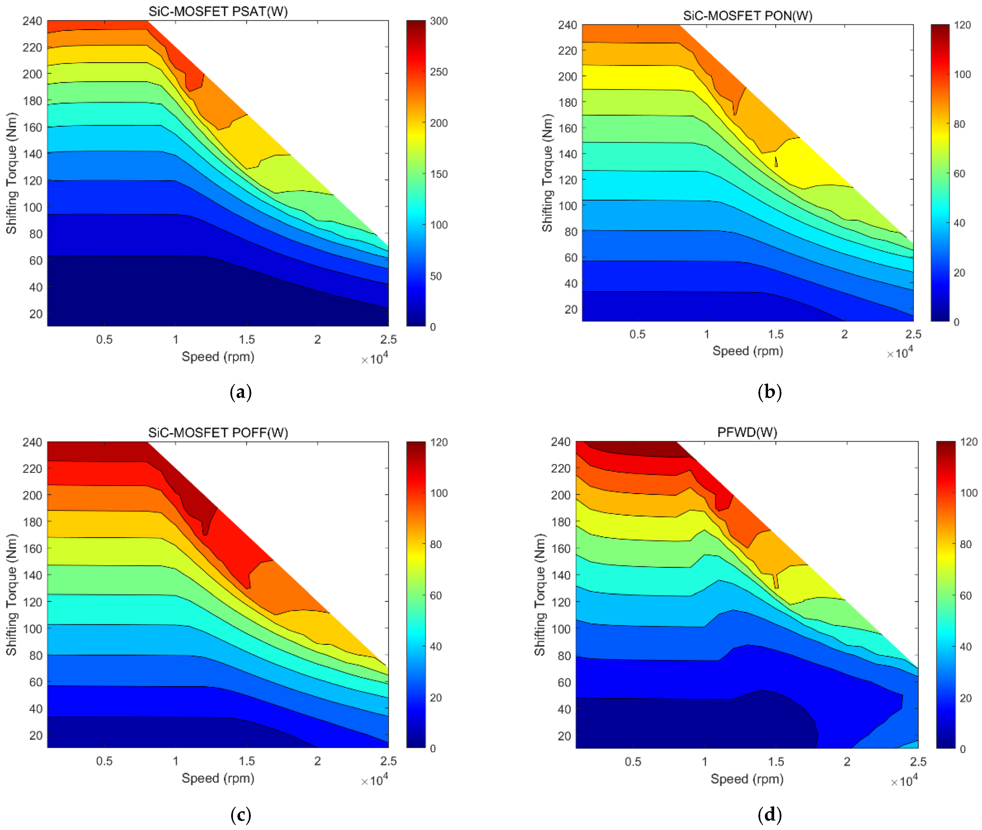
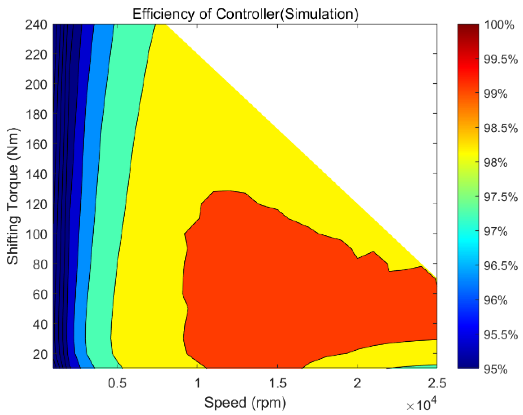
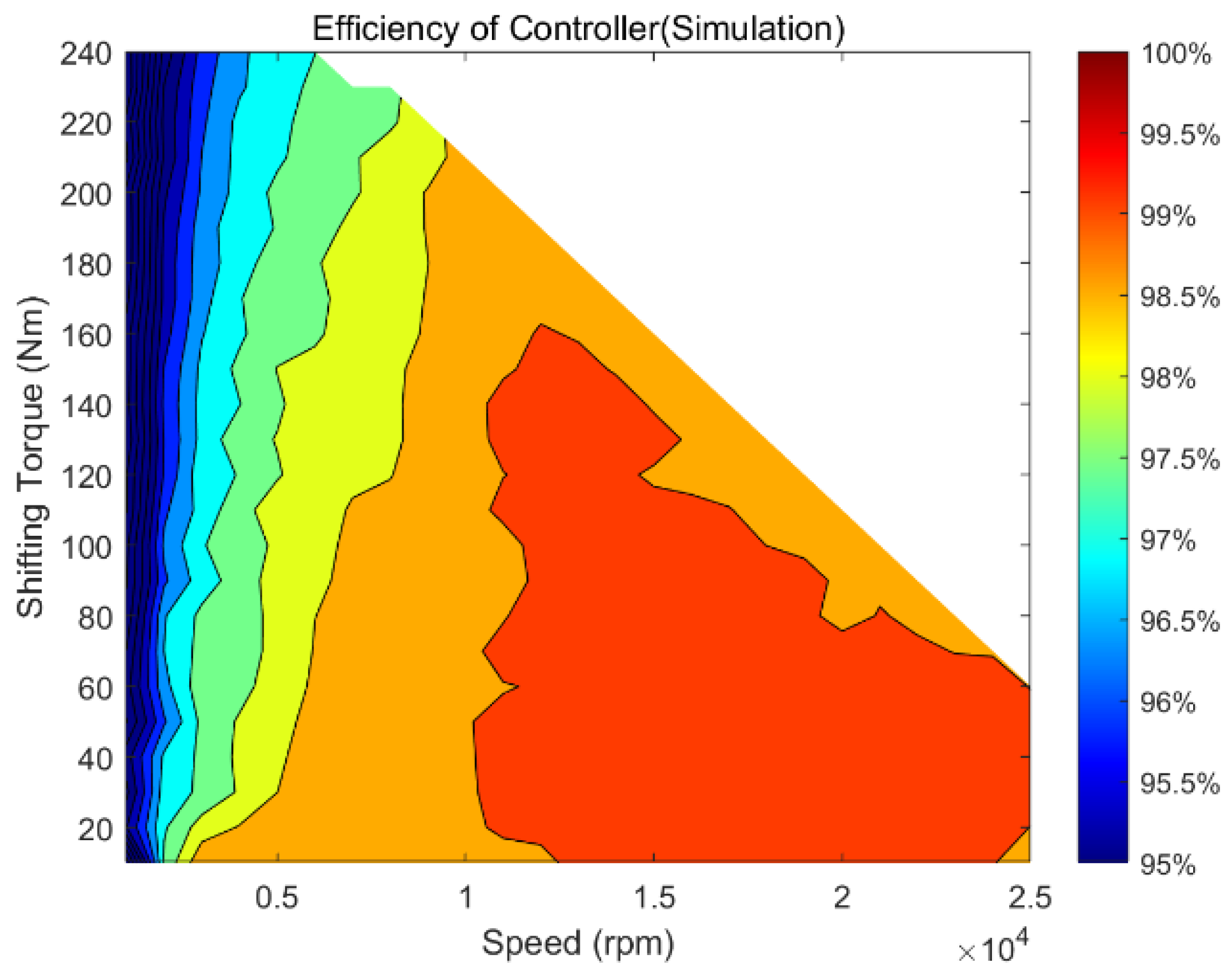
3.2. Power Module Efficiency Simulation

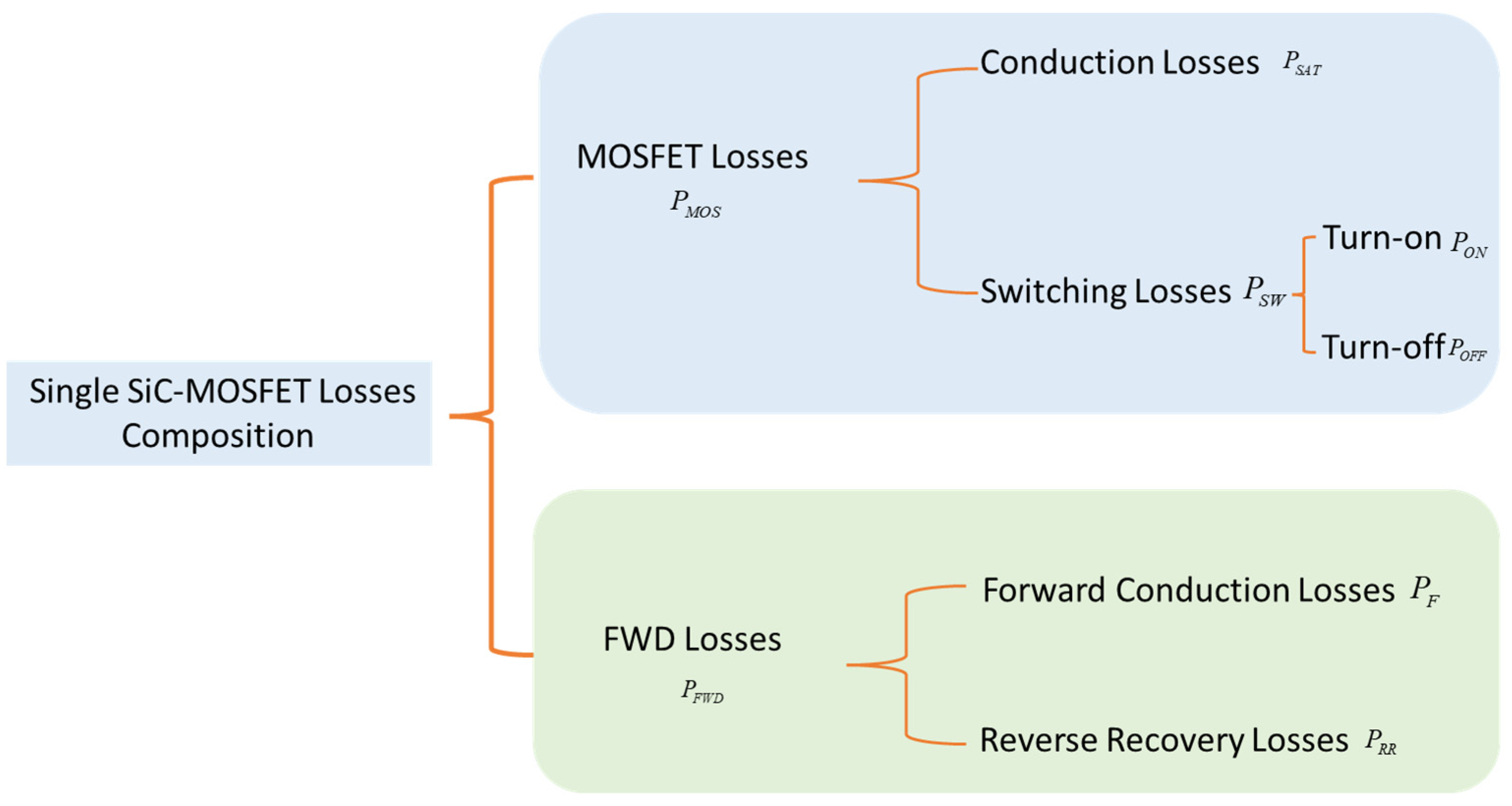
Components of Power Module Losses

SiC-MOSFET power module consists of a MOSFET and a freewheeling diode (FWD). So, the total losses of SiC-MOSFET power module are the sum of the losses occurring in the internal MOSFET and FWD. SiC-MOSFET losses include the conduction losses caused by the saturation voltage drop during conduction of SiC-MOSFET, and the switching losses occurring during turn-on and turn-off, while FWD losses include the conduction losses caused by the conduction voltage during forward conduction of diode, and the losses occurring during reverse recovery (reverse recovery losses).
The composition of the SiC-MOSFET power module losses described above is shown in Figure 19.
A simulation model is constructed to estimate the efficiency of the motor controller, and the simulation conditions are shown in Table 5.
The losses occurring in each part of the controller under different operating conditions are shown in Figure 20. Overall, the losses are positively correlated with the power of the controller, and conduction losses account for the largest proportion.
The efficiency simulation results of the control system are shown in Figure 21. The efficiency of the control system is above 90% under all operating conditions, especially 92.23% of the area above 95%, and the highest efficiency reaches 99.9%.

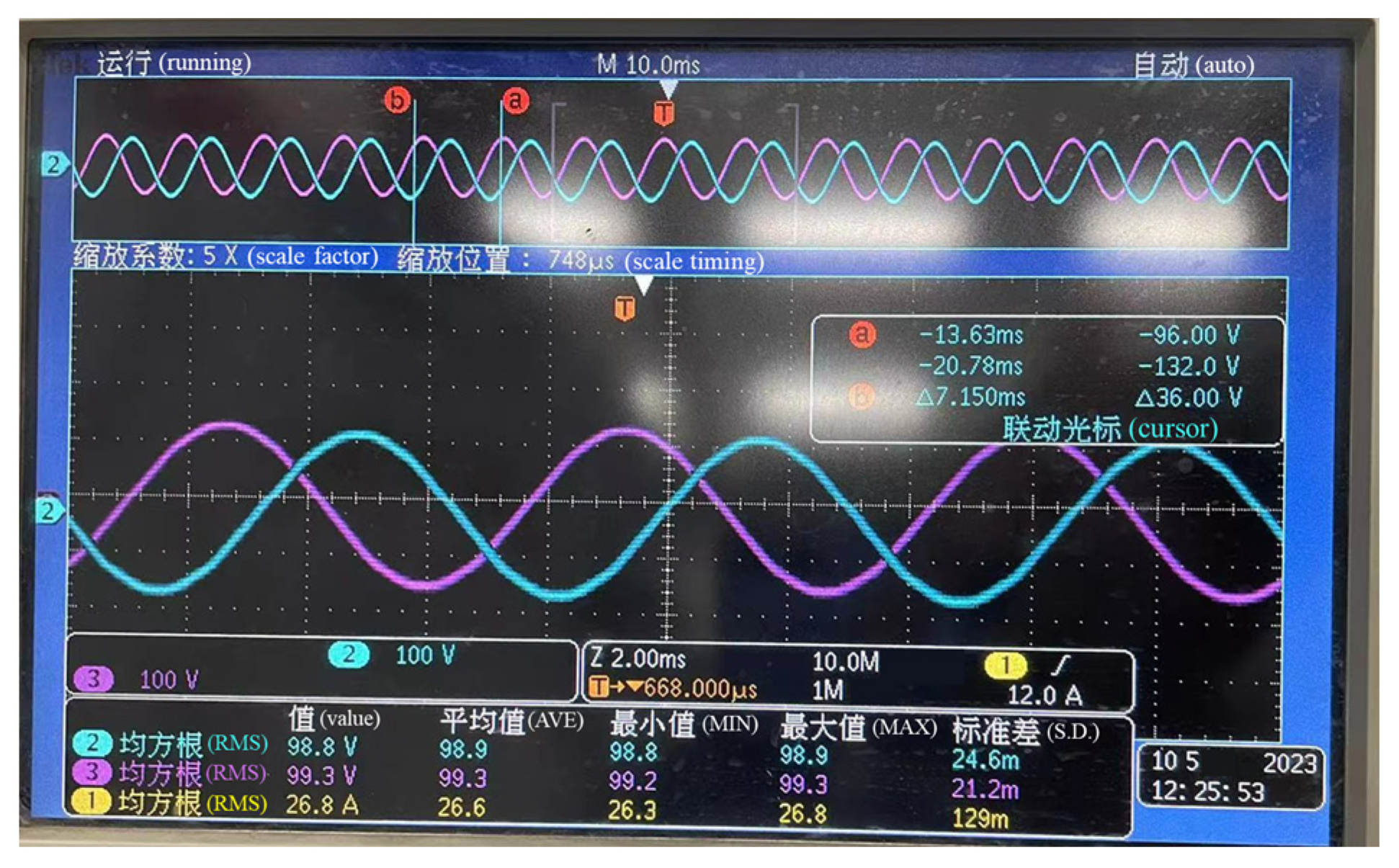
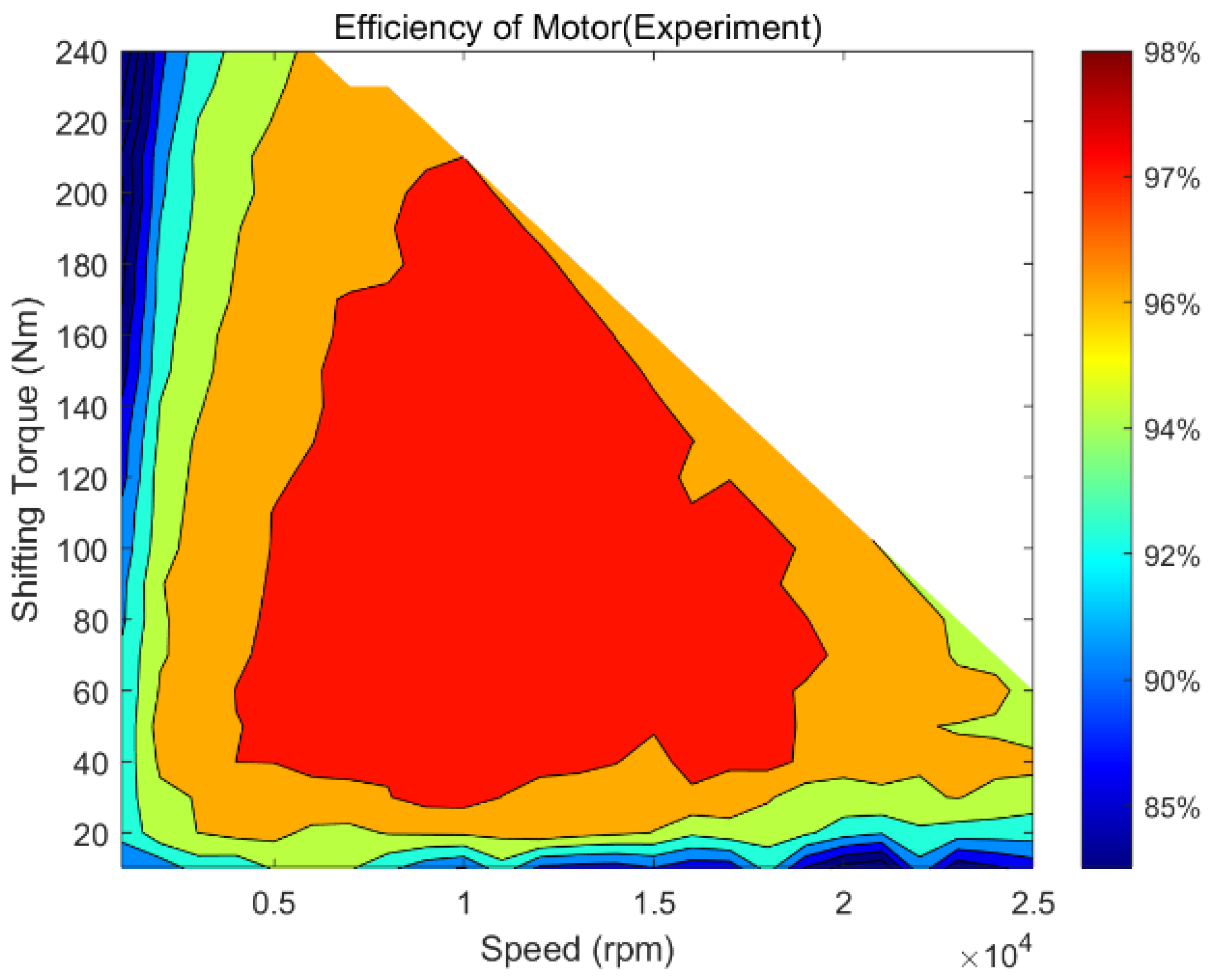
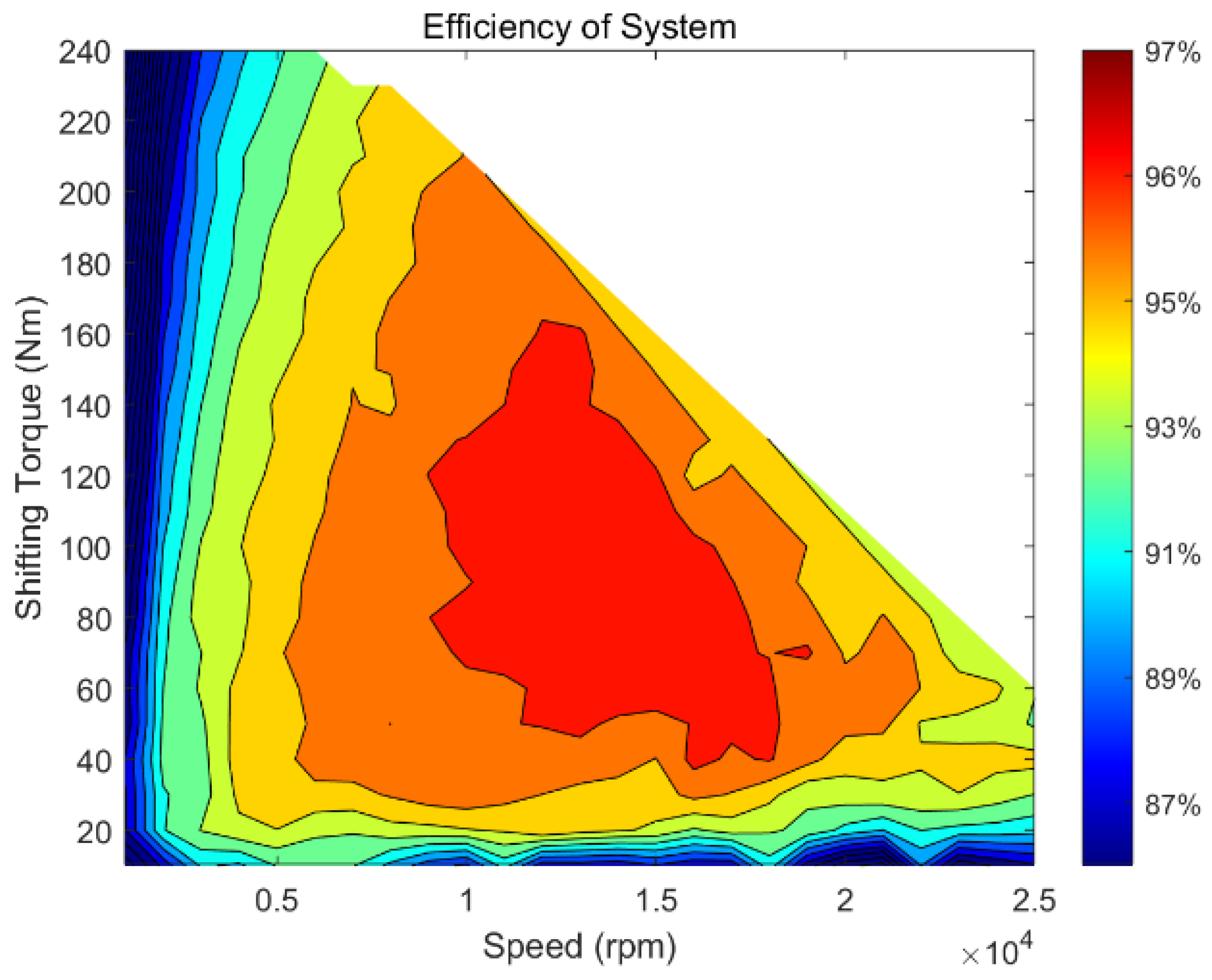
3.3. Analysis of the Motor System Experiment

The prototype of motor and controller were made to according to the design in this paper. The stator and rotor are shown in Figure 22 and Figure 23.
The experimental platform was built to test and verify the design. The bench test site is shown in Figure 24. The main measuring instruments used in the experiment include a high-speed dynamometer system, IK5-G0-410HI, made by Shinko electric, Co., Ltd, Minato-ku, Japan.; a torque sensor, T40B, made by HBM (Darmstadt, Germany); and a scope, CT1000, made by Yokogawa China Co., Ltd. (Shanghai, China).
The back EMF at 3000 rpm 25 °C is shown in Figure 25. The root-mean-square value of the back EMF is 98.8 V under this condition. The efficiency map of the controller is shown in Figure 26. More than 93.23% of the areas in the graph have controller efficiencies over 95%. The highest efficiency of the controller exceeds 99%. When the speed is 12,000 rpm and the torque is 90 Nm, the conduction losses of SiC-MOSFET are 50.4 W, and the conduction losses of FWD are 26.5 W. The losses of SiC-MOSFET occurring during turn-on and turn-off are 39.2 W and 43.4 W, respectively. The reverse recovery losses of FWD are 0.66 W. The simulation efficiency of the controller is 99.18%, and the measured efficiency under this condition is 99.25%. The error between simulation and measurement is 0.07%.
The highest efficiency of the high-speed motor is 98%. The efficiency map is shown in Figure 27. In this figure, 90.2% of the areas have an efficiency higher than 90%.
The measured efficiency map of the motor driving system is shown in Figure 28. The system achieves a maximum efficiency of 97.33%, with 83.42% of the zones being above 90% and 93.7% of the zones in the efficiency map being above 85%. At a speed of 9000 rpm and a torque of 90 Nm, the simulated efficiency is 97.46% according to the simulation results. The measured efficiency is 97.06%, and the error between them is only 0.41%.
The main parameters of the motor system are shown in Table 6. The power density of the controller reaches 47.94 kW/L, the peak power is 241.16 kW, and the volume is 5.03 L. Similarly, the power density of the motor reaches 2.3 kW/kg, its peak power is more than 200 kW, and the weight is just 87 kg. The total cost increases by CNY 2755, mainly on SiC-MOSFET. The advantage of cost will gradually become prominent in the future, since the price of SiC-MOSFET has declined significantly in recent years.

4. Summary

This paper optimizes the design of an EV motor system on a 800 V high-voltage platform. The main work and achievements are as follows: (1) A motor controller with 800 V high-voltage and peak power greater than 200 kW is designed using a SiC-MOSFET power module. (2) The design of an EV high-speed motor with a maximum speed of more than 25,000 rpm was completed, and the losses of the motor were optimized from different aspects. The efficiency of the optimized motor was significantly improved. (3) The loss components of SiC-MOSFET power module are introduced, and the efficiency of the controller is simulated based on this. (4) The experiment is carried out to verified the design, and the results are consistent with the theoretical analysis.

Author Contributions

K.Z.: Conceptualization: Ideas; formulation or evolution of overarching research goals and aims. Methodology: Development or design of methodology; creation of models. Software: Programming; Formal analysis; Data Curation; Writing—Original Draft; Visualization. M.G.: Resources: laboratory samples, computing resources, Writing—Review & Editing. Supervision, Project administration. Y.Z.: Writing—Review & Editing, Supervision, Project administration. Funding acquisition. All authors have read and agreed to the published version of the manuscript.

Funding

This project is from Dongfeng Motor Corporation, Wuhan 430056, China.

Data Availability Statement

Data are contained within the article.

Conflicts of Interest

Authors Kun Zhou, Minglei Gu were employed by the company Dongfeng Motor Corporation. The remaining authors declare that the research was conducted in the absence of any commercial or financial relationships that could be construed as a potential conflict of interest.

References

  1. Abualnaeem, M.M.; Zulkifli, S.A.B.M.; Bin Yahaya, N.Z.; Soomro, H.A. Comparison of Power Loss in SiC-MOSFET and Si-IGBT Traction Inverter with Variable Switching Frequency for Electric Vehicle Application. In Proceedings of the 2024 IEEE Symposium on Industrial Electronics & Applications (ISIEA), Kuala Lumpur, Malaysia, 6–7 July 2024; pp. 1–6. [Google Scholar] [CrossRef]
  2. Zheng, H.; Wang, X.; Wang, X.; Ran, L.; Zhang, B. Using SiC MOSFETs to improve reliability of EV inverters. In Proceedings of the 2015 IEEE 3rd Workshop on Wide Bandgap Power Devices and Applications (WiPDA), Blacksburg, VA, USA, 2–4 November 2015; pp. 359–364. [Google Scholar] [CrossRef]
  3. Allca-Pekarovic, A.; Kollmeyer, P.J.; Mahvelatishamsabadi, P.; Mirfakhrai, T.; Naghshtabrizi, P.; Emadi, A. Comparison of IGBT and SiC Inverter Loss for 400V and 800V DC Bus Electric Vehicle Drivetrains. In Proceedings of the 2020 IEEE Energy Conversion Congress and Exposition (ECCE), Detroit, MI, USA, 11–15 October 2020; pp. 6338–6344. [Google Scholar] [CrossRef]
  4. Yu, Y.; Li, H.; Yu, Z.; Ding, L. Power Loss Analysis of Powertra in Inverter with SiC MOSFETs and Si IGBT for 400V and 800V Battery Voltage. In Proceedings of the 2024 IEEE 7th International Electrical and Energy Conference (CIEEC), Harbin, China, 10–12 May 2024; pp. 5064–5069. [Google Scholar] [CrossRef]
  5. Takatsuka, Y.; Hara, H.; Yamada, K.; Maemura, A.; Kume, T. A wide speed range high efficiency EV drive system using winding changeover technique and SiC devices. In Proceedings of the 2014 International Power Electronics Conference (IPEC-Hiroshima 2014—ECCE ASIA), Hiroshima, Japan, 18–21 May 2014; pp. 1898–1903. [Google Scholar] [CrossRef]
  6. Guo, Q.; Zhang, C.; Li, L.; Wang, M.; Wang, T. Efficiency optimization control of permanent magnet synchronous motor system with SiC MOSFETs for electric vehicles. In Proceedings of the 2017 20th International Conference on Electrical Machines and Systems (ICEMS), Sydney, NSW, Australia, 11–14 August 2017; pp. 1–5. [Google Scholar] [CrossRef]
  7. Dong, T.; Kwak, J.; Wei, L.; Castellazzi, A.; Nakamura, T. High Power-Density High-Efficiency Electric Drive Design with Halbach-Rotor PMSM and WBG-Based High-Frequency Inverter. In Proceedings of the 2021 24th International Conference on Electrical Machines and Systems (ICEMS), Gyeongju, Republic of Korea, 31 October–3 November 2021; pp. 1759–1762. [Google Scholar] [CrossRef]
  8. Ju, X.; Cheng, Y.; Ding, L.; Cui, S. Analysis and Design of Multi-Pole High-Speed IPMSM with SiC Based Inverters for EVs. In Proceedings of the 2020 International Conference on Electrical Machines (ICEM), Gothenburg, Sweden, 23–26 August 2020; pp. 1704–1710. [Google Scholar] [CrossRef]
  9. Hiroki, T.; Kohei, A. Performances comparison of PMSM and SRM for EV aiming for maximum speed of 50,000 min−1. In Proceedings of the 2024 IEEE Transportation Electrification Conference and Expo, Asia-Pacific (ITEC Asia-Pacific), Xi’an, China, 10–13 October 2024; pp. 623–627. [Google Scholar] [CrossRef]
  10. Bai, J.; Zhu, X.; Xiang, Z. Electromagnetic Vibration Improvement for a High-Speed Flat Wire PM Motor Based on Optimal Magnetic-Pole Boundary. IEEE Trans. Magn. 2024, 60, 8202006. [Google Scholar] [CrossRef]
  11. Yan, H.; Du, G.; Li, N.; Li, L.; Chen, Y.; Lei, G.; Zhu, J. Four Rotor Structures for High-Speed Interior Permanent Magnet Motor Considering Mechanical, Electromagnetic, and Thermal Performance. IEEE Trans. Transp. Electrif. 2025, 11, 2595–2608. [Google Scholar] [CrossRef]
  12. Ying, H.; Huang, S.; Xu, D. An high-speed low-noise rotor topology for EV/HEV PMSM. CES Trans. Electr. Mach. Syst. 2017, 1, 354–359. [Google Scholar] [CrossRef]
  13. Kumar, P.; Kumar, R.; Kumar, B.; Kumar, A. Design of a High Performance PMSM for Electric Vehicles. In Proceedings of the 2022 2nd International Conference on Emerging Frontiers in Electrical and Electronic Technologies (ICEFEET), Patna, India, 24–25 June 2022; pp. 1–5. [Google Scholar] [CrossRef]
  14. Ju, X.; Cheng, Y.; Yang, M.; Cui, S.; Sun, A.; Liu, X.; He, M. Voltage Stress Calculation and Measurement for Hairpin Winding of EV Traction Machines Driven by SiC MOSFET. IEEE Trans. Ind. Electron. 2022, 69, 8803–8814. [Google Scholar] [CrossRef]
  15. Allca-Pekarovic, A.; Kollmeyer, P.J.; Reimers, J.; Mahvelatishamsabadi, P.; Mirfakhrai, T.; Naghshtabrizi, P.; Emadi, A. Loss Modeling and Testing of 800-V DC Bus IGBT and SiC Traction Inverter Modules. IEEE Trans. Transp. Electrif. 2024, 10, 2923–2935. [Google Scholar] [CrossRef]
  16. 16 Hong, D.-K.; Woo, B.-C.; Lee, J.-Y.; Koo, D.-H. Ultra High Speed Motor Supported by Air Foil Bearings for Air Blower Cooling Fuel Cells. IEEE Trans. Magn. 2012, 48, 871–874. [Google Scholar] [CrossRef]
  17. Han, Y.; Lu, H.; Li, Y.; Chai, J. Analysis and Suppression of Shaft Voltage in SiC-Based Inverter for Electric Vehicle Applications. IEEE Trans. Power Electron. 2019, 34, 6276–6285. [Google Scholar] [CrossRef]
  18. Mei, L.; Xiao, W.; Cui, J.; Zhang, Q.; Liu, Z. Analytical Modeling and Pole–Slot Combination Selection Analysis of a Direct-Drive Drilling Permanent Magnet Synchronous Motor. Processes 2023, 11, 3222. [Google Scholar] [CrossRef]
  19. Jung, Y.-H.; Kim, K.-O.; Lim, M.-S. Performance Improvement of Rare-Earth Free High-Speed Multilayer IPMSM Using Dual-Phase Magnetic Material. IEEE Trans. Magn. 2023, 59, 8205105. [Google Scholar] [CrossRef]
  20. Cha, J.; Yoon, J.; Koo, J.; Uijong, B.; Sim, K.; Hahn, S. Loss Reduction and Operating Time Extension Using Segmented HTS Field Coil Bobbin for High-Speed Operation of EV Traction Motor. IEEE Trans. Appl. Supercond. 2024, 34, 5201705. [Google Scholar] [CrossRef]
  21. Song, X.; Han, B.; Zheng, S.; Chen, S. A Novel Sensorless Rotor Position Detection Method for High-Speed Surface PM Motors in a Wide Speed Range. IEEE Trans. Power Electron. 2018, 33, 7083–7093. [Google Scholar] [CrossRef]
  22. Muranaka, K.; Nakamura, T.; Okajima, S.; Ogasa, T.; Amemiya, N.; Itoh, Y. Experimental and Analytical Studies on Variable Speed Control of High-Temperature Superconducting Induction/Synchronous Motor. IEEE Trans. Appl. Supercond. 2016, 26, 5201205. [Google Scholar] [CrossRef]
  23. Mao, K.; Zheng, S.; Liu, G. Analysis and suppression of magnetically levitated rotor vibration influence for high-speed permanent magnet motor sensorless control. In Proceedings of the 2016 19th International Conference on Electrical Machines and Systems (ICEMS), Chiba, Japan, 13–16 November 2016; pp. 1–6. [Google Scholar]
  24. Li, Y.; Song, X.; Zhou, X.; Huang, Z.; Zheng, S. A Sensorless Commutation Error Correction Method for High-Speed BLDC Motors Based on Phase Current Integration. IEEE Trans. Ind. Inform. 2020, 16, 328–338. [Google Scholar] [CrossRef]
  25. Ok, S.; Xu, Z.; Lee, D.-H. A Sensorless Speed Control of High-Speed BLDC Motor Using Variable Slope SMO. IEEE Trans. Ind. Appl. 2024, 60, 3221–3228. [Google Scholar] [CrossRef]
  26. Song, Q.; Sun, P.; Wang, M. IPMSM Loss Reduction Control Under High-Speed Conditions for Electric Vehicles. IEEE J. Emerg. Sel. Top. Power Electron. 2024, 12, 2306–2316. [Google Scholar] [CrossRef]
  27. Hu, F.; Luo, D.; Luo, C.; Long, Z.; Wu, G. Cascaded Robust Fault-Tolerant Predictive Control for PMSM Drives. Energies 2018, 11, 3087. [Google Scholar] [CrossRef]
  28. Testing. CLTC Test Standard: A New Energy Vehicle Endurance Test Method Designed for the Chinese Market. [EB/OL]. 2024. Available online: https://www.auto-testing.net/baike/show-3383.html (accessed on 10 March 2025).
Figure 1. Principle of 800 V high-voltage motor system.
Actuators 14 00216 g001
Figure 2. Efficiency maps of different silicon steels.
Actuators 14 00216 g002
Figure 3. Relationship between frequency and core loss.
Actuators 14 00216 g003
Figure 4. Optimizing the pole–slot coordination.
Actuators 14 00216 g004
Figure 5. Double-V type magnetic pole.
Actuators 14 00216 g005
Figure 6. Different connection processes. (a) Rivet connection. (b) Weld. (c) Adhesive. Hint: The red circle means the damage to connection points of different processes.
Actuators 14 00216 g006
Figure 7. Rotor mechanical stress (1.2 times overspeed).
Actuators 14 00216 g007
Figure 8. Rotor plastic strain (1.2 times overspeed).
Actuators 14 00216 g008
Figure 9. Rotor steady-state equivalent strength test.
Actuators 14 00216 g009
Figure 10. Gate drive circuit.
Actuators 14 00216 g010
Figure 11. PMSM control algorithm block diagram.
Actuators 14 00216 g011
Figure 12. Back EMF and external characteristic of high-speed motor. (a) EMF. (b) External characteristic.
Actuators 14 00216 g012
Figure 13. Magnetic density cloud of motor. (a) Rated power. (b) Peak power.
Actuators 14 00216 g013
Figure 14. Ripple of peak torque.
Actuators 14 00216 g014
Figure 15. Stator current and losses map. (a) D−axis current. (b) Q−axis current. (c) Copper loss. (d) Iron loss.
Actuators 14 00216 g015
Figure 16. Map of dq-axis inductance of motor. (a) D−axis inductance. (b) Q−axis inductance.
Actuators 14 00216 g016
Figure 17. Permanent magnet flux map.
Actuators 14 00216 g017
Figure 18. Motor efficiency map.
Actuators 14 00216 g018
Figure 19. Composition of the SiC-MOSFET power module losses.
Actuators 14 00216 g019
Figure 20. Controller losses simulation map. (a) Conduction losses. (b) Turn-on losses. (c) Turn-off losses. (d) FWD losses.
Actuators 14 00216 g020
Figure 21. Control system losses simulation map.
Actuators 14 00216 g021
Figure 22. Stator of high-speed motor.
Actuators 14 00216 g022
Figure 23. Rotor of high-speed motor.
Actuators 14 00216 g023
Figure 24. Bench test site.
Actuators 14 00216 g024
Figure 25. EMF at 3000 rpm.
Actuators 14 00216 g025
Figure 26. Efficiency of control system.
Actuators 14 00216 g026
Figure 27. Efficiency of motor.
Actuators 14 00216 g027
Figure 28. Measured efficiency map of motor system.
Actuators 14 00216 g028
Table 1. Different-thickness carbon fiber rotor failure test.
Thicknesses of Carbon Fiber (mm)Small V-StructureLarge V-Structure
Yield Speed (rpm)Burst Speed (rpm)Yield Speed (rpm)Burst Speed (rpm)
030,15032,25023,890224,850
0.332,25034,75025,70026,950
0.634,20035,55026,00027,700
0.834,35035,85027,15028,150
Table 2. Relationship between EMF and efficiency.
EMF (V)101411091158
Peak torque (Nm)228236240
Peak power (kW)211216221
Maximum efficiency (%)97.4297.4997.53
CLTC efficiency (%)94.8194.9194.85
Rated point efficiency (%)97.2997.3997.43
Table 3. Main parameters of electromagnetic design of the high-speed motor.
ParametersValueParametersValue
DC-link voltage (V)700Poles6
Peak power (kW)≥200Stator slots54
Peak torque (Nm)≥200Flat line layers8
CoolingOilSilicon steel20SW1200
Magnet steel50 UHStandard wire/mm3.565 × 1.635
Rated phase current (RMS)/A156.7Stator outer diameter/mm200
Maximum efficiency97.5%Stator inner diameter/mm122.6
Ripple torque3% (Peak torque)Rotor outer diameter/mm119.4
Power density≥6 kW/kg (without axis)Rotor inner diameter/mm48
Air gap length/mm1.6Maximum speed/rpm25,000
Length/mm126//
Table 4. Basic parameters of SiC-MOSFET.
Model V D S ( max ) (V) V G S ( max ) (V) I D ( n o m ) (A)
ZM600FB12W31200−5/18450
R D S ( o n ) (Ω) V G S ( t h ) (V) E o n (J) E o f f (J)
3.2 m (85 °C)3.234 m (85 °C)60 m (85 °C)
Table 5. Simulation conditions.
Driving resistance Rg (Ω)6.75
DC-link rated voltage (V)700
Temperature (°C)150
Driving voltage Vgs (V)+18, −5
Switching frequency10 kHz at all speed
Table 6. Main performance parameters of motor system.
ParameterValue
Controller volume (L)5.03
Motor weight (kg)87
Motor assembly size (X × Y × Z) (mm)542 × 504 × 414.5
Peak power of controller (kW)241.16
Peak power of motor (kW)>200
Cost comparing with 400 V System (CNY)SiC-MOSFET: +2000;
High-voltage bus capacitor: +200;
High-voltage EMC: +200;
Oil cooling: +55;
Motor axis: +55;
Motor assembly: +320;
Material: −75;
Disclaimer/Publisher’s Note: The statements, opinions and data contained in all publications are solely those of the individual author(s) and contributor(s) and not of MDPI and/or the editor(s). MDPI and/or the editor(s) disclaim responsibility for any injury to people or property resulting from any ideas, methods, instructions or products referred to in the content.

