Article

Development of a Force Feedback Controller with a Speed Feedforward Compensator for a Cable-Driven Actuator

by
Juan Fang
1,*,
Michael Haldimann
1,2,
Bardia Amiryavari
1 and
Robert Riener
2,3
1
rehaLab—The Laboratory for Rehabilitation Engineering, Institute for Human Centred Engineering HuCE, School of Engineering and Computer Science, Bern University of Applied Sciences, Postfach, CH-2501 Biel, Switzerland
2
Sensory-Motor Systems (SMS) Lab, Institute of Robotics and Intelligent Systems, Department of Health Sciences and Technology, ETH Zurich, CH-8092 Zurich, Switzerland
3
SCI Center, University Hospital Balgrist, Medical Faculty, University of Zurich, CH-8008 Zurich, Switzerland
*
Author to whom correspondence should be addressed.
Actuators 2025, 14(5), 214; https://doi.org/10.3390/act14050214
Submission received: 7 March 2025 / Revised: 17 April 2025 / Accepted: 21 April 2025 / Published: 25 April 2025

Abstract

:
Cable-driven actuators (CDAs) are extensively used in the rehabilitation field because of advantages such as low moment of inertia, fast movement response, and intrinsic flexibility. Accurate control of cable force is essential for achieving precise movement control, especially when the movement is generated by multiple CDAs. However, velocity-induced disturbances pose challenges to accurate force control during dynamic movements. Several strategies for direct force control have been investigated in the literature, but time-consuming tests are often required. The aim of this study was to develop a force feedback controller and a speed feedforward compensator for a CDA with a convenient experiment-based approach. The CDA consisted of a motor with a gearbox, a cable drum, and a force sensor. The transfer function between motor torque and cable force was estimated through an open-loop test. A PI force feedback controller was developed and evaluated in a static test. Subsequently, a dynamic test with a reference force of 100 N was conducted, during which the cable was pulled to move at different speeds. The relationship between the motor speed and the cable force was determined, which facilitated further development of a speed feedforward compensator. The controller and compensator were evaluated in dynamic tests at various speeds. Additionally, the system dynamics were simulated in MATLAB/Simulink. The static test showed that the PI force controller produced a mean force control error of 4.7 N, which was deemed very good force-tracking accuracy. The simulated force output was very similar to the experiment (RMSE error of 4.0 N). During the dynamic test, the PI force controller alone produced a force control error of 9.0 N. Inclusion of the speed feedforward compensator improved the force control accuracy, resulting in a mean error at various speeds of 5.6 N. The combined force feedback controller and speed feedforward compensator produced a satisfactory degree of accuracy in force control during dynamic tests of the CDA across varying speeds. Additionally, the accuracy level was comparable to that reported in the literature. The convenient experiment-based design of the force control strategy exhibits potential as a general control approach for CDAs, laying the solid foundation for precise movement control. Future work will include the integration of the speed compensator into better feedback algorithms for more accurate force control.

1. Introduction

As a promising auxiliary paradigm for the physiotherapists, rehabilitation robotic systems are employed to implement various neuromuscular therapies [1]. Among different robotic structures, cable-driven robotic systems are frequently used to provide 3D natural movement guidance. Due to advantages such as versatile configuration, low moment of inertia, fast movement response, and intrinsic flexibility [2,3], cable-driven actuators (CDAs) have been applied in diverse fields ranging from astronomy [4], aerospace [5], construction [6], to medical engineering [7]. The review paper [8] summarises various applications of CDAs, highlighting the versatility and effectiveness of CDAs across different industries. In rehabilitation engineering, CDA-based robotic systems offer intuitive and effective guidance for comprehensive whole-body recovery. Examples of CDAs for upper limb rehabilitation include the 3D shoulder support CAREX [9], the Parallel Cable-Driven Upper Limb Rehabilitation Robot [10], and the r3-system, which is a reconfigurable rope robot for rowing simulation [11], tennis play [12], and bed translational control [13]. Representative utilisations of CDAs in body support include the Active Tethered Pelvic Assist Device (A-TPAD) [14], the Trunk Support Trainer (TruST) [15], and a device for body reloading and unloading [2,16,17]. Typical applications of CDAs in lower-limb rehabilitation include the Cable-driven Active Leg Exoskeleton C-ALEX [18] and the system for gait restoration [3]. A flexible robotic system, 3DCaLT [19], has been widely implemented in patients with different neurological impairments, demonstrating significant potential for enhancing walking function.
To secure performance of CDAs in various applications, intensive research has been performed on the optimisation of mechanical structures [20], evaluation of workspace characteristics [21], analysis of system stiffness [10], vibration suppression [22], and development of movement control strategies [3]. The paper [23] presents the state-of-the-art advancements in these research areas. Regarding movement control, many studies address topics such as adaptive position control [24,25,26], tension distribution optimisation [11,23], model parameter identification for tension prediction [27,28], and sagging prevention [29,30], while the algorithms for CDAs to produce the required cable tension have not been fully reviewed.
A good force control strategy is the basic requirement for movement regulation with balance and stability [31,32]. Control of cable-driven robotic systems typically involves two levels of controllers: high-level position controllers in the outer loop and low-level force controllers in the inner loop [14,16,18,33]. The force controller typically calculates appropriate motor torque to track the desired target force, an approach known as direct force control. Alternatively, many indirect force control methods regulate force through manipulation of cable position or velocity. Notable approaches include compensating for cable elasticity [34,35], incorporating various types of springs [36], or employing admittance-based algorithms [37,38,39,40,41]. However, the current study focuses on algorithms for direct force control, wherein CDAs operate in torque mode.
A variety of control algorithms have been investigated to enhance direct force control performance. Force control in static situations, such as during isometric training, is relatively straightforward. As force control requires fast response, traditional controllers such as PD [42] or lead controllers [43] are often used. The lead controller in study [43] produced an error of 4.79% to track a sinusoidal target force. An integral term removes the steady-state error. In the application of CDAs in the body weight support mechanism, a PID controller produced an error of 3.78% in tracking a sinusoidal target force in the static test [44]. Apart from static situation, cable-driven robotic systems are widely applied in dynamic movement training where the cable has to follow a specific movement trajectory. The movement induces kinetic changes, such as the target human–robot interaction force, the required torque for the drive components, and the nonlinear friction within the CDA [33]. These kinetic changes bring disturbances to dynamic control of force in the cable. Consequently, motion-induced disturbances make it challenging to achieve accurate dynamic force control. Both experimental and theoretical strategies have been explored in the literature.
Force control during movement has been frequently developed, with control parameters determined through experimental tests. In the development of Myoshirt [33], which is a cable-driven exosuit that supports the shoulder joint during functional arm elevation, a PI force controller with friction compensation was implemented. The r3-system employed a force control strategy that included a simple proportional controller, a friction compensator, and an additional feedforward term [12]. Study [45] used a proportional controller for force control, but the friction was approximated with a linear function with the cable speed. Studies [46,47] implemented a lag controller to filter the high-frequency control signals, apart from an adaptive position compensation. C-ALEX [18] and A-TPAD [14] used a similar control strategy, which consists of three parts: a PID feedback controller, a feedforward term using the motor constant, and a friction compensator. These studies primarily relied on experiments to develop their control strategies without investigating the system transfer function. However, experimental-based friction compensation requires repetitive tests to find the accurate model for friction [40].
In parallel to the experimental approach, theoretical analysis of system dynamics has also been performed in the development of force control strategies. The research group led by Zhang et al. developed various cable-driven robotic systems [2,3,10]. By modelling the cable in each CDA as a spring–damper mechanism, they derived the transfer function from motor torque to force output as a third-order system. The force control strategy was composed of a second-order phase-lead feedback element, apart from an integral element and a feedforward element of a constant gain. The disturbance caused by motor speed was also analysed. Based on the structure invariance principle, a compensator was designed as a third-order system. These algorithms achieved good accuracy in force control and were applied in upper-limb rehabilitation [10], lower-limb rehabilitation [3], and general body reloading and unloading [2,16]. We previously developed a system with four CDAs to assist walking on the treadmill [43,48]. Based on a model with a spring–damper element for each CDA, we developed for each CDA a force feedback lead controller and a velocity feedforward lead compensator. The algorithms produced satisfactory force control accuracy. However, effective disturbance rejection depends upon an accurate dynamic model of the CDA. Identification of CDA dynamics involves sophisticated estimation of many system parameters and time-consuming dynamic tests for model validation.
An accurate control strategy for force regulation of the cable is a fundamental requirement for the application of cable-driven robotic systems. These robotic systems often involve simultaneous interaction of multiple CDAs. The movement-induced disturbances can potentially excite vibration due to the low stiffness and low damping properties of CDAs [22,23]. Therefore, it is desirable to develop a convenient and accurate force control strategy for each CDA, as preparation for higher-level position control of multiple CDAs.
The aim of this work was to develop a force feedback controller and a speed feedforward compensator for a CDA using an experiment-based method. To test the control algorithms, the CDA was applied in dynamic arm training. The structure of this paper is outlined as follows: after an overview of the mechanical structure of the CDA, Section 2 details the development of the control algorithms. Section 3 presents the identified system dynamics, controller parameters, and test results. Section 4 compares the test results with the existing literature and highlights the innovations of the work. Section 5 presents concise conclusions. It was expected that a force control strategy would be conveniently developed based on experimental data. Without careful investigation for friction compensation or theoretical derivation of the system dynamics, the developed control strategy would produce satisfactory force control accuracy, which is comparable to values in the literature.

2. Methods

Using the System Identification Toolbox (The MathWorks, Inc., Natick, MA, USA, Version 2024a), the dynamic model of the CDA was determined. The relationship between motor speed and force output was identified. The force control strategy was developed and simulated in MATLAB/Simulink. The real-time control algorithms were implemented at a sample rate of 1000 Hz in TwinCAT3 (Beckhoff Automation GmbH & Co., Verl, Germany). The static and dynamic test results were compared with the simulated results in MATLAB/Simulink. The tests were performed on a healthy person (age of 28 yrs, height of 1.74 m, body mass of 85 kg), with the selection criterion of being able to perform neuromuscular training of the arm with a load higher than 150 N. Since the data are not generalisable, they do not fall under the Swiss Federal Act on Research Involving Human Beings. No ethical approval was needed.

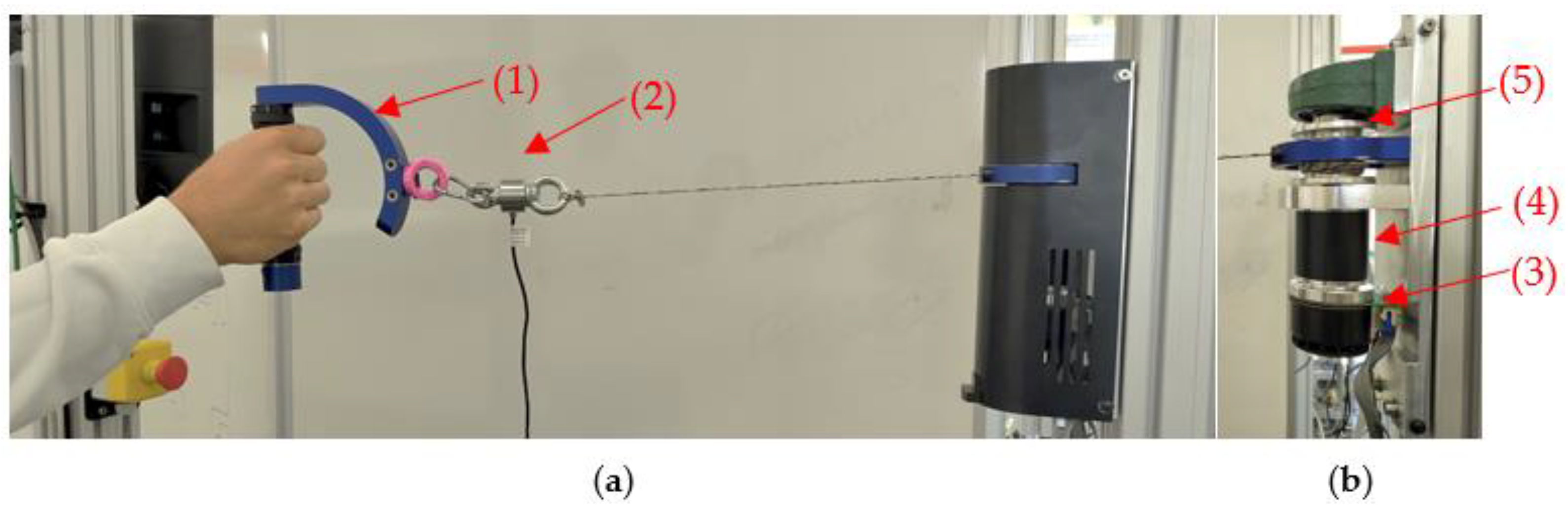
2.1. Mechanical Description

The CDA (Figure 1) consists of a drive assembly (Part No.: 625861, maxon motor, Sachseln, Switzerland), a drum (diameter of 0.04 m), and a force measurement unit (Bengbu Sensor Company, Bengbu, China). The drive assembly includes a motor (EC60, nominal speed: 3020 rpm, nominal torque: 0.581 Nm), an encoder (1024 Counts per turn, 2 channels), and a gearbox (ratio of 49/4). A servo controller (EPOS4 Compact 50/8 with EtherCAT interface, maxon motor, Switzerland) with two analogue-input channels was used and ran in torque mode. The force measurement unit consists of a force sensor and an amplifier, which can measure the force between −500 N and 500 N. The force signal was recorded using the analogue-input channel of the servo controller and had a resolution of 0.012 N. The CDA was previously employed in arm training [44] and body weight support [49]. In the current study, the CDA was employed for arm training to evaluate the developed control algorithms.

2.2. Force Control Strategy Development

The control strategy includes a force feedback controller and a speed feedforward compensator. After the plant dynamics were determined using the System Identification Toolbox, the control strategy was derived, simulated, and evaluated.

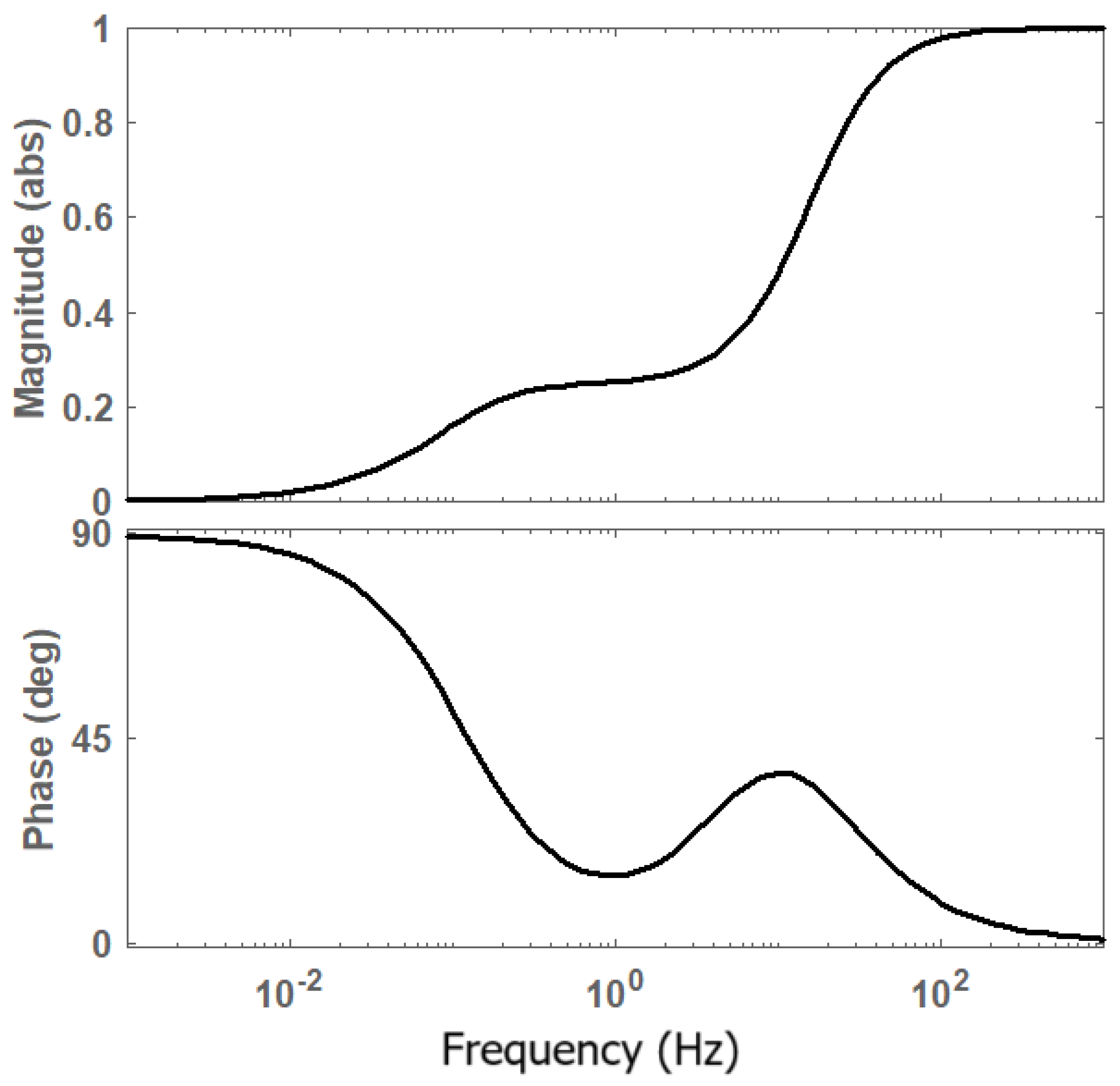
2.2.1. System Identification

Development of the control strategy requires dynamic analysis of the system, which was performed based on experimental data from static and dynamic tests.
In the static test, the cable was held still by the test person. The elasticity of the cable was neglected. According to Newton’s second law, the cable force in a steady static state should exhibit a proportional relationship to the motor torque, governed by a gain k. After considering the time required for the force to achieve the final value in the physical system, a first-order transfer function was used to approximate the dynamics of the CDA. A first-order transfer was also used in a study of a similar force control setup [50]. Therefore, the transfer function Po, which shows the relationship between motor torque T and cable force F, is as follows:
T F : P o ( s ) = k τ s + 1 ;
where k and τ are the gain and the time constant. The two parameters were determined through System Identification Toolbox using data obtained from an open-loop test, as described below.
A series of square-wave torque signals was sent to the motor. The test person held the handle still by resisting the force produced by the CDA. Five measurements were conducted with square-wave torque at magnitude of 25% and 50% of the maximal torque. The motor torque and the actual force measurements were collected. The System Identification Toolbox was utilised to develop the mathematical model of the system dynamics. The experimental data from the open-loop test, i.e., the motor torque and the actual force, were used as the input and the corresponding output response of the system. The data were preprocessed to remove the mean. Then, a transfer function Po with no zeros and one pole was estimated. The goodness of fit of the transfer function Po was specifically investigated using a normalised root-mean-square error (NRMSE) on an evaluation interval from t0 to t1:
N R M S E = 1 t = t 0 t 1 [ F exp ( t ) F s i m ( t ) ] 2 t = t 0 t 1 [ F exp ( t ) F exp ( t ) ¯ ] 2 × 100 % ;
where Fexp and Fsim are the force from the experiment and the value from the first-order transfer function Po. F exp ¯ is the mean of Fexp between t0 and t1.
As explained in the introduction and also shown in Section 3, the force control accuracy was influenced by the motor speed. In order to find the relationship between motor speed and force control, an additional speed identification test was performed during dynamic movement, where the feedback controller (developed in Section 2.2.2) was implemented in the CDA, where a reference resistive load of 100 N was defined. The cable was pulled by the test person to follow a sinusoidal position trajectory, where a metronome was used to control the movement rhythm. The cable was pulled in synchronisation with the beat and then retracted with the subsequent beat. A metronome beat was set to be 60 BPM, which corresponds to a sinusoidal movement at a frequency of 0.5 Hz. The speed was filtered through a low-pass filter Dlp as follows:
D l p ( s ) = 1 1 ω l p s + 1 ;
where ωlp is the cut-off frequency of the filter, which was set to be 100 rad/s. The data from the closed-loop test, i.e., the filtered motor speed and the cable force, were used as the input and the corresponding output response of the system. The data were preprocessed to remove the means. The relationship between the motor speed and the force output, Pω, was searched for using the System Identification Toolbox. Given the spring–damper property of the cable, a transfer function with one zero and two poles was estimated:
ω F ω : P ω ( s ) = g ω 1 s + g ω 0 s 2 + h ω 1 s + h ω 0 ;
where gω0, gω1, hω0, and hω1 are the real coefficients to be determined through the System Identification Toolbox.

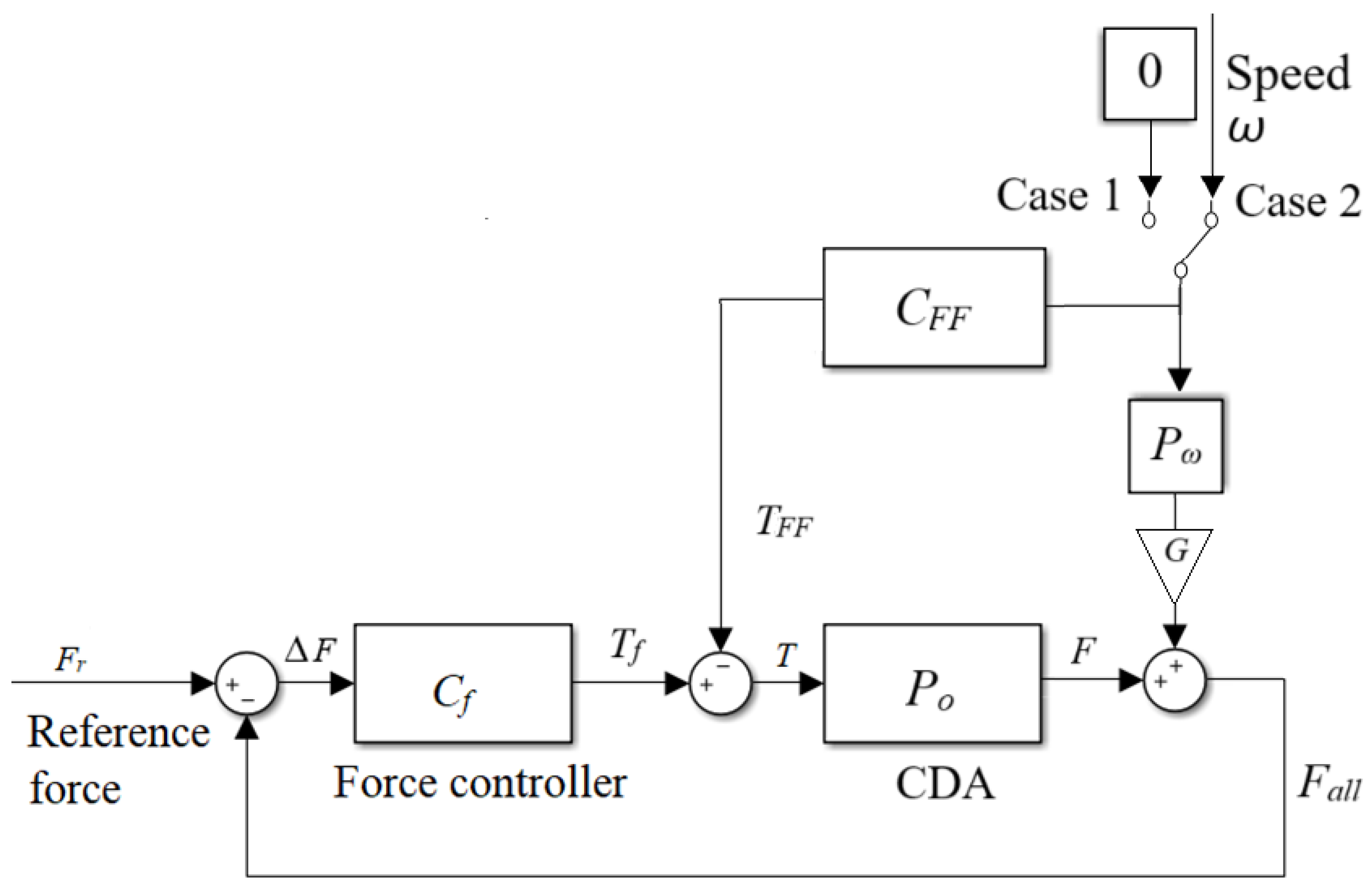
2.2.2. Derivation of Force Control Strategy

The control strategy consists of a force feedback controller Cf (Case 1 in Figure 2) for static isometric training and an additional speed feedforward compensator CFF (Case 2 in Figure 2) for dynamic training.
In order to produce a user-defined profile of resistance training, a PI force controller Cf was implemented. The input to Cf is ΔF, which is the difference between the reference force Fr and all force Fall. The output from Cf is the target torque Tf to the CDA. The transfer function of Cf is as follows:
Δ F T f : C f ( s ) = k p f ( 1 + k i f s ) ;
where kpf and kif are the proportional and integral gains.
The disturbance Pω from the speed ω is shown in Figure 2. A gain G was introduced to compensate for the attenuation effect of the control loop Cf on the disturbance. Using closed-loop control theory, the transfer function of disturbance on the output, So, should be as follows:
S o = 1 1 + C f P o ;
The Bode diagram of So shows that the disturbance input will appear in the force output with a phase shift and with some change in the amplitude Gd. The gain G, as shown in Figure 2, should be as follows:
G = 1 G d ;
The aim of the compensator CFF is to remove the influence of the disturbance Pω on the cable force Fall, which means
ω C F F P o + ω P ω G = 0 .
Therefore, CFF was obtained as follows:
C F F = P ω G P o 1 .
The effect of the feedforward strategy was compared by running the PI controller Cf only (Case 1 in Figure 2) and the PI controller Cf plus the feedforward compensator CFF (Case 2 in Figure 2). In both cases, the cable of the CDA was pulled and retracted according to the metronome beats of 60, 50, and 40 BPM, respectively.

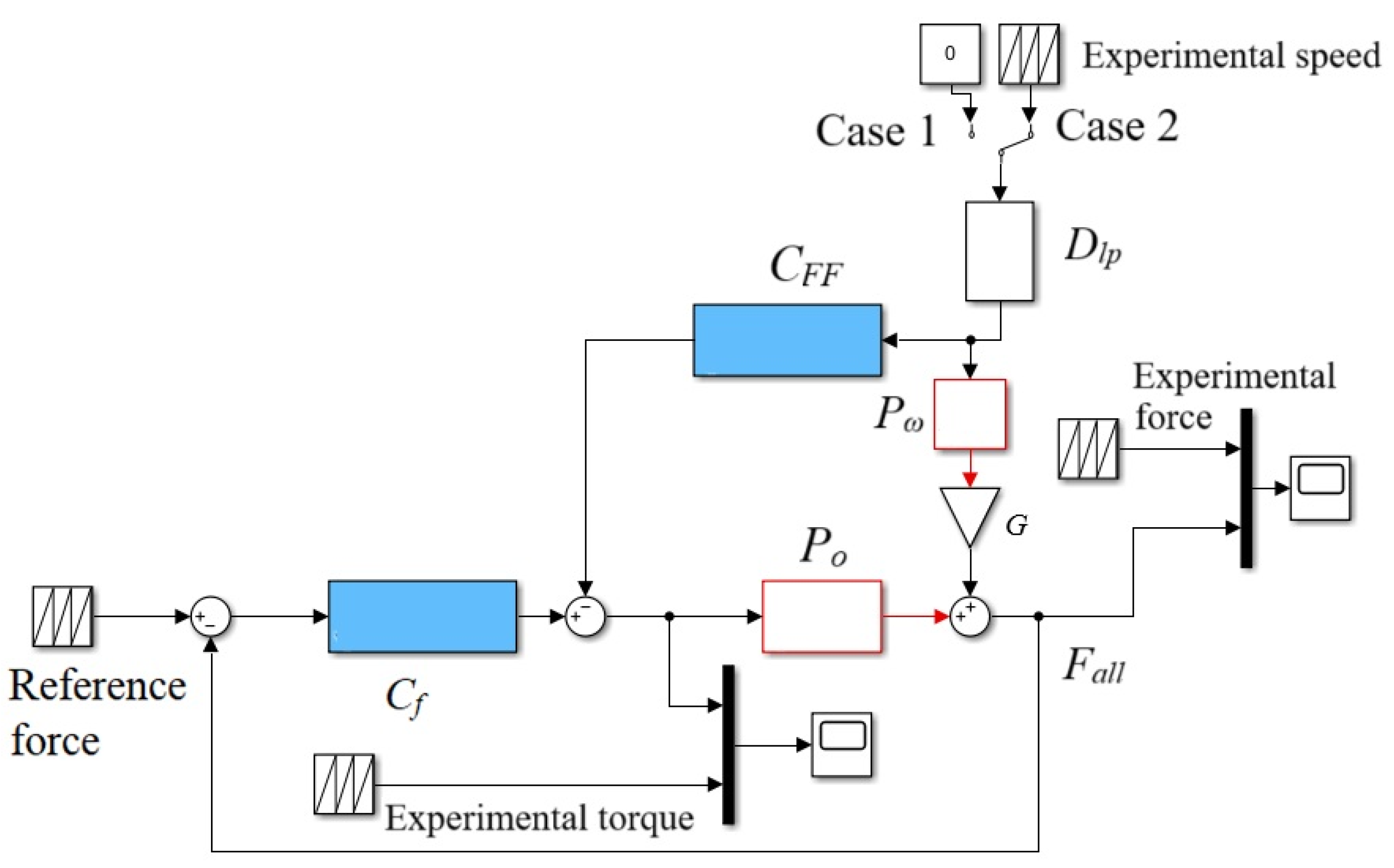
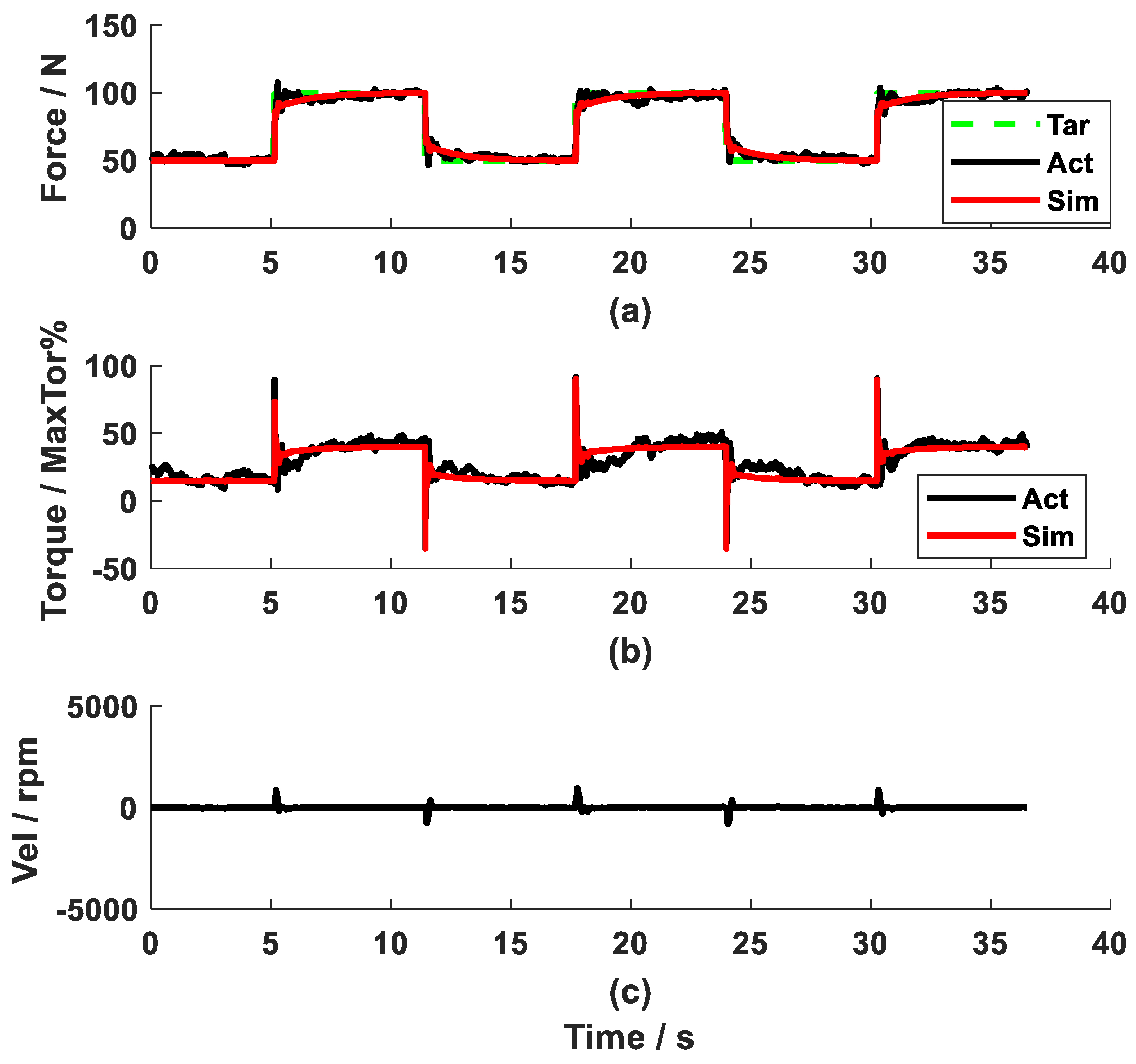
2.3. Simulation of Force Control Strategy
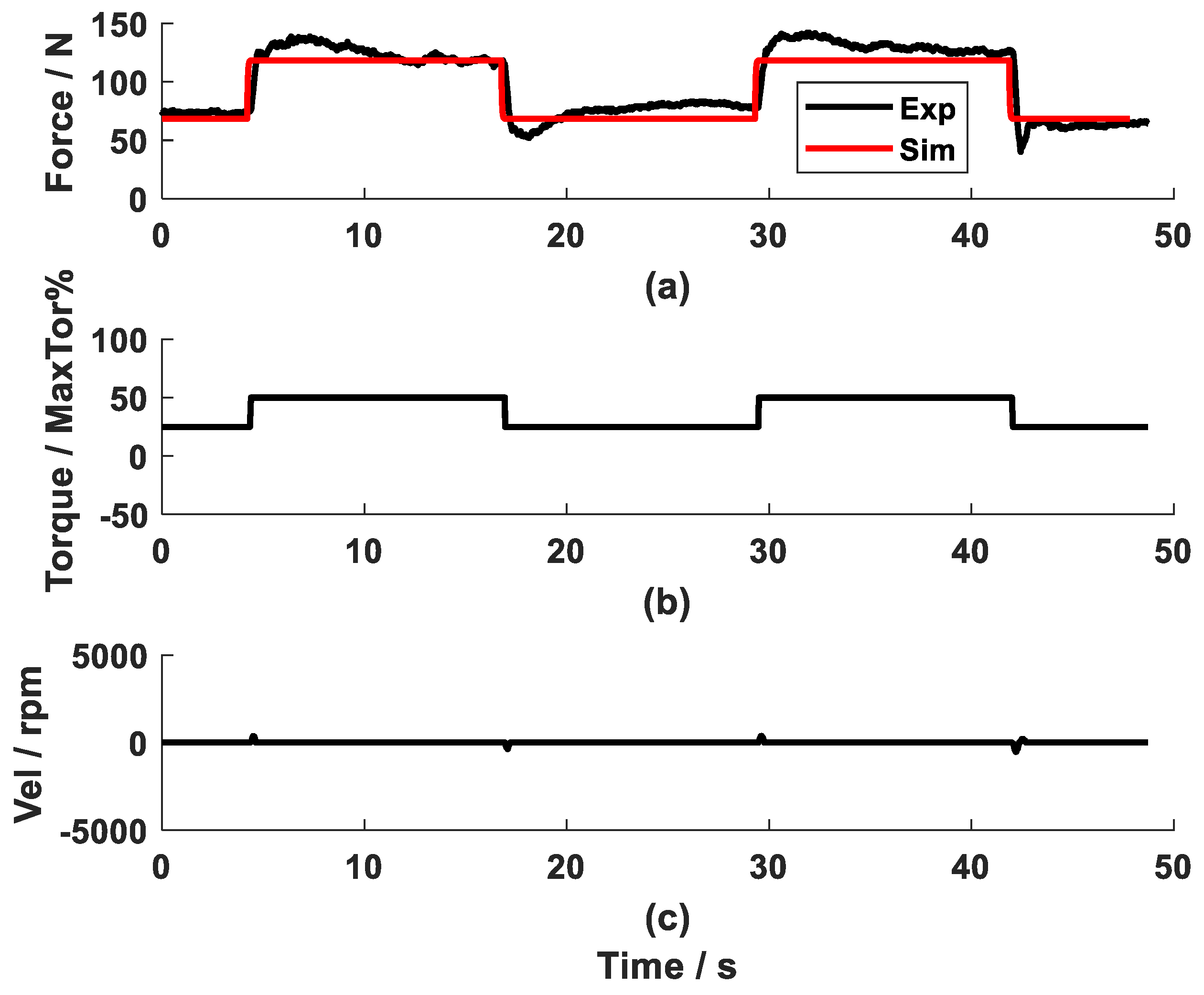
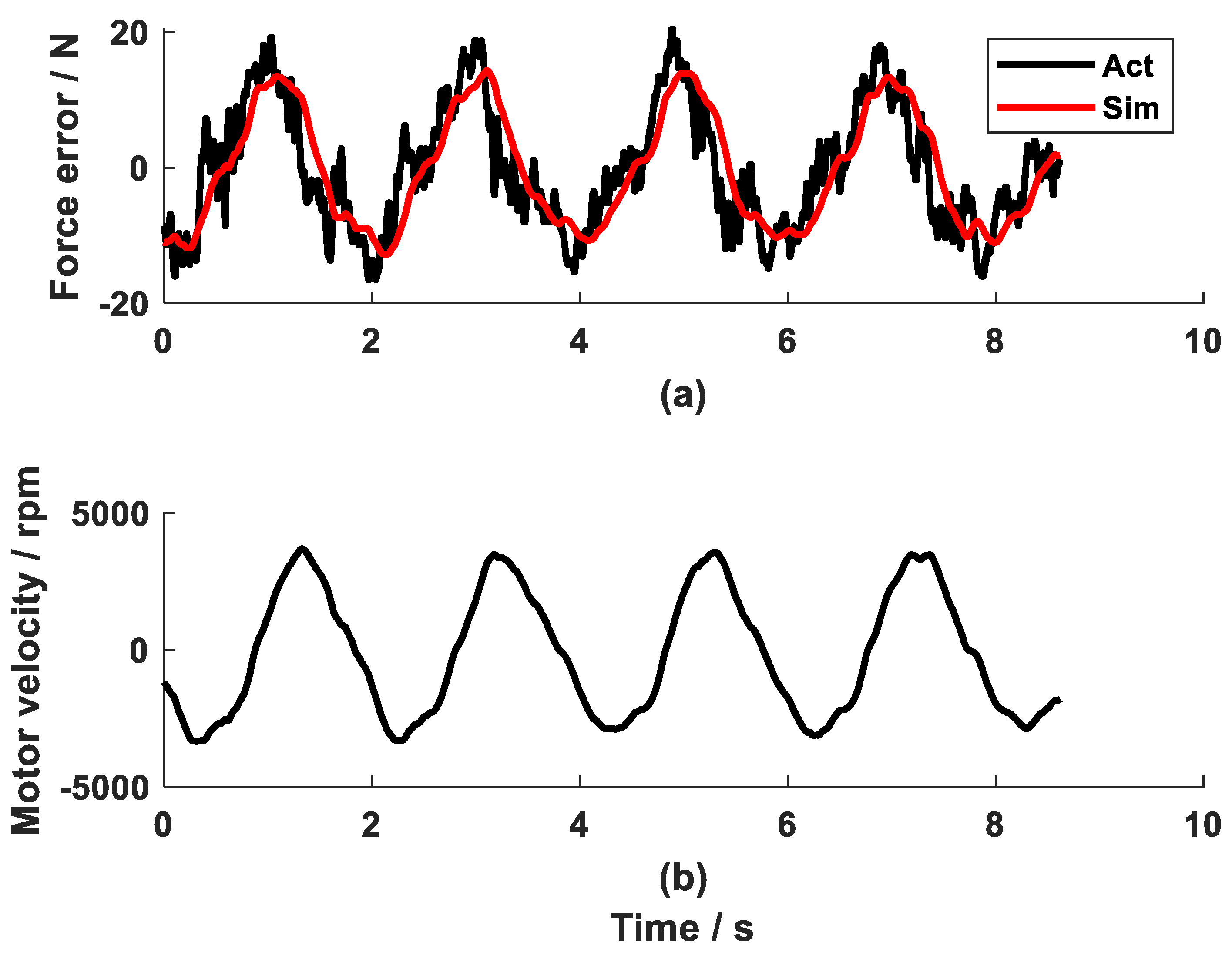
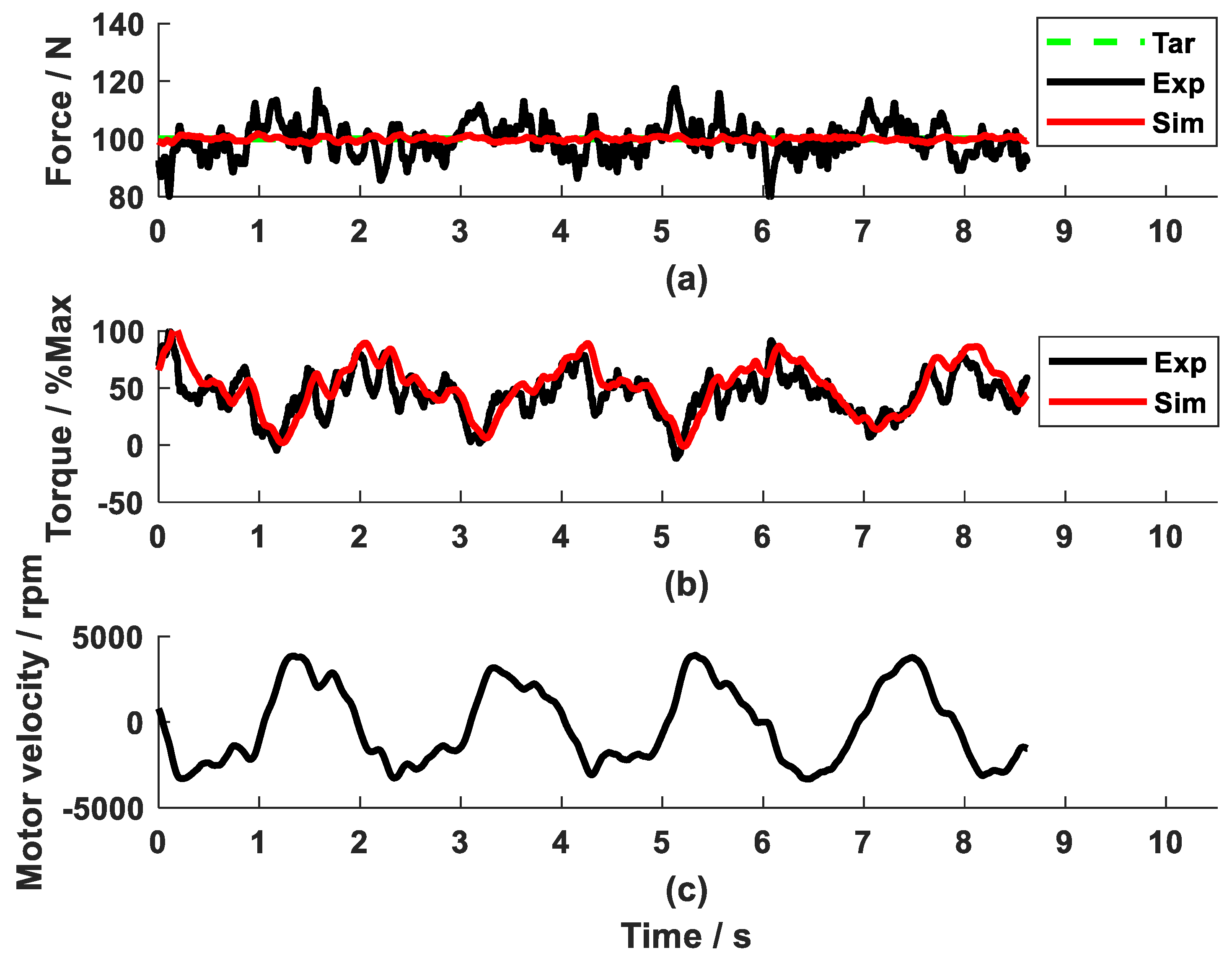
To verify the plant dynamics (Po and Pω) and to validate the control algorithms (Cf and CFF), a dynamic model of the CDA (Figure 3) was developed in MATLAB/Simulink. The CDA was represented using the experimentally developed transfer function Po (Equation (1)). The speed disturbance Pω (Equation (4)), the feedback controller Cf (Equation (5)), and the feedforward compensator CFF (Equation (9)) were simulated. The reference force as used in the experiment and the experimental speed were used as the inputs for the model. A fixed-step solver ODE 3 (Bogacki–Shampine) with a fixed-step size of 0.001 s was used. The simulated results, such as motor torque and cable force, were compared with the experimental motor torque and cable force.
To evaluate the model’s accuracy, the root-mean-square error (RMSE) of the force output RMSE_Fexp_sim and the torque RMSE_Texp_sim are calculated at an evaluation interval from t0 to t1:
R M S E _ F exp _ s i m = 1 N t = t 0 t 1 ( F a l l _ exp ( t ) F a l l _ s i m ( t ) ) 2 ;
R M S E _ T exp _ s i m = 1 N t = t 0 t 1 ( T exp ( t ) T s i m ( t ) ) 2 ;
where N is the number of data points in the interval t0 to t1. To evaluate the force-tracking accuracy from the control strategy, RMSE_Fexp_r, which is the RMSE between the experimental force output Fall_exp and the reference force Fr, is calculated as follows:
R M S E _ F exp _ r = 1 N t = t 0 t 1 ( F a l l _ exp ( t ) F r ( t ) ) 2 .
Similarly, the RMSE between the simulated force output Fall_sim and the reference force Fr is calculated using the following:
R M S E _ F s i m _ r = 1 N t = t 0 t 1 ( F a l l _ s i m ( t ) F r ( t ) ) 2 .
For the force test, we defined an error smaller than 5%, i.e., an RMSE smaller than 5 N for a reference force of 100 N, as a very good force control strategy for general arm muscle training. A strategy that produces an error between 5 N and 7.5 N is deemed as a satisfactory strategy. These criteria were determined based on subjective testing feedback and insights from the relevant literature. It was observed that a force difference was barely felt during dynamic movement when the error was below 7.5 N. Furthermore, these criteria align closely with findings from studies [33,51,52], where the force controllers for the CDA produced an error between 5% and 7.5%. The same criteria were used to evaluate model simulation: an RMSE_Fexp_sim smaller than 5 N or between 5 N and 7.5 N is considered as a very good or satisfactory simulation.

3. Results

In the open-loop test, 25% and 50% of the maximal torque produced a mean force of 72 N and 125 N (Figure 4a,b), respectively. Although the test person tried to keep the handle static by resisting the force produced by the torque pulses, the cable still moved slightly (Figure 4c). The System Identification Toolbox yielded the system parameters k = 2.0 and τ = 0.03. Therefore, the transfer function Po is as follows:
P o ( s ) = 2.0 0.03 s + 1 .
Equation (2) yielded a goodness of fit of 57%.
The gains of the PI feedback controller were tuned by experience to be kpf = 15 and kif = 1. Therefore, the feedback controller Cf is as follows:
C f ( s ) = 15 s + 15 s .
The evaluation static test showed that the CDA produced good static force control with an RMSE_Fexp_r of 4.9 N for the square-wave reference force (Figure 5) and 4.5 N in the sinusoidal reference force (Figure 6). The simulated control signal, which is the torque to the motor, presented a similar curve as the experimental control signal (RMSE_Texp_sim of 5.8% of the maximal torque in Figure 5b and 6.2% of the maximal torque in Figure 6b). The simulated force output was similar to the experimental output (RMSE_Fexp_sim of 3.1 N in Figure 5a and 4.8 N in Figure 6a). This means that the model produced very good simulation results. Figure 5 and Figure 6 prove that the plant parameters Po were acceptable, and the PI controller produced very good force-tracking accuracy in the static test.
In contrast to the very good force-tracking accuracy in the static test, repetitive pulling and retracting movement of the cable yielded a large force error in tracking the reference force when the PI controller alone was used. As shown in Figure 7, an RMSE_Fexp_r of 9.0 N was observed during a rhythmic pull at 60 BPM. Regarding the simulation results of the dynamic tests, the simulated force and the control torque sign for the motor (the red line in Figure 7a,b) with the PI force feedback controller only were close to the corresponding experimental value (the black line in Figure 7a,b) with an RMSE_Fexp_sim of 4.4 N and an RMSE_Texp_sim of 9.2%. It was observed that the experimental and simulated force outputs (the black and red lines in Figure 7a) had a similar shape to the speed profile (Figure 7c) but with a lower amplitude and a certain phase shift.
The Bode diagram of So demonstrates how the motor speed signal influences the system’s force output. As shown in Figure 8, speed signals with a frequency higher than 100 Hz almost reappear in the force output. The physical movement frequency range during arm training is between 20 and 240 BPM, i.e., 0.17–2.0 Hz. Within this frequency range, the signal appears in the force output with an amplitude reduced to 0.21–0.27 times and a phase shift of 15–24°.
The test data during movement at 60 BPM (Figure 7) show an input velocity with a frequency of about 0.5 Hz. The Bode diagram (Figure 8) shows that for this velocity frequency, the amplitude is 0.246, i.e., Gd = 0.246, while the phase shift is only 17.53°. Therefore, in the control diagram (Figure 2 and Figure 3), the gain G was set to be 4 (using Equation (7)).
Based on the experimental data, the relationship of the motor speed ω and the force Fω was identified as follows:
P ω ( s ) = 0.8502 s + 0.07474 s 2 + 132.1 s + 615.3 .
Equation (2) yielded a goodness of fit of 68.1% (Figure 9a). Therefore, the implemented feedforward compensator, using Equation (9), is as follows:
C F F ( s ) = 1.02 s 2 + 3.41 s + 0.299 0.2 s 2 + 26.42 s + 123.1 .
Implementing the feedforward compensator and the PI feedback controller, the dynamic test showed an RMSE_Fexp_r of 5.6 N (Figure 10), which is a satisfactory force control accuracy. Compared to Figure 7, the feedforward compensator reduced the force error by 3.4 N.
As far as the development of the speed compensator is concerned, the simulated force output (red line in Figure 10a) is very close to the reference force (dashed black line in Figure 10a) with an RMSE_Fsim_r of 0.8 N. Such a negligible difference proved that the developed feedforward compensator (Equation (17)) was theoretically correct. In the simulation for the combined PI force feedback controller and the speed compensator, the simulated and the experimental forces (the red and black lines in Figure 10a) were similar, with an RMSE_Fexp_sim of 5.4 N. This result shows that the model with the force feedback controller plus the speed feedforward compensator yielded a satisfactory simulation. The difference between the simulated and experimental torque (the red and black lines in Figure 10b) RMSE_Texp_sim is 18.8%. The experimental target torque to the motor Texp, due to factors such as the force measurement noise, system friction, and spring–damper property of the cable, is more dynamic than the simulated torque Tsim. Nevertheless, the simulated torque and the experimental torque share a similar curve shape. Due to the simplification of plant Po and the approximation of the disturbance Pω in the Simulink model, it was expected that the experimental force control accuracy with the feedforward compensator (black line in Figure 10a) was not as good as the simulated result (red line in Figure 10a).
The feedforward compensator was tested at various speeds. As seen in Figure 11, the experimental force output at 50 and 40 BPM tracked the reference force satisfactorily, with an RMSE_Fexp_r of 5.5 N (Figure 11a) and 5.6 N (Figure 11d), respectively. The control signals calculated by the PI controller and the compensator are shown in Figure 11b,e. It was observed that the torque produced by the PI controller was similar in both cases, while the torque from the feedforward compensator exhibited a larger amplitude range at 50 BPM than at 40 BPM, because the motor velocity at 50 BPM was higher. The speed feedforward compensator, developed based on the data from 60 BMP, also compensated the disturbances produced by the movements at 40 BPM and 50 BPM.

4. Discussion

Accurate control of cable tension during movement is essential for effective application of cable-driven robotic systems in rehabilitation. In this work, we developed a force feedback controller and a speed feedforward compensator for a CDA, which produced satisfactory force control during movement at various speeds. Using experimental data, the system dynamics and the speed disturbance were identified, which enabled the development of the feedback controller and feedforward compensator. Evaluation tests proved that the control strategy was very good in static force control and satisfactory in dynamic arm training at various speeds. The force control strategy served as a solid foundation for the further development of the high-level position control of CDAs, which needs to be produced by general cable-driven rehabilitation systems.
The PI force feedback controller produced very good control accuracy in the static test of the CDA. While the CDA offers a user-friendly physical interface, the soft cable property and the nonlinear dynamics of CDA during movement make it challenging to control the cable force accurately. In the current study, the conventional PI controller was employed, which produced very good accuracy in static force control (mean RMSE_Fexp_r of 4.7 N). Such conventional controllers were often used in the literature [14,18,33]. The advantage of this approach is that it does not require an accurate plant model. As system simulation in this study and the further development of the speed compensator required a system model, we still worked out the transfer function of the CDA. Instead of theoretical derivation [3,16], we simplified the CDA dynamics to be a first-order system, which yielded a goodness of fit of 57%. The fit might be increased by integrating the spring–damper property of the cable and the nonlinear behaviour of the cable stiffness into system identification. It requires further investigation whether approximation of the system with a first-order system affected the force control accuracy. Nevertheless, the simulated force output and the control signal are close to the experimental results (mean RMSE_Fexp_sim of 4.0 N, mean RMSE_Texp_sim of 6.0% of the maximal torque). It was demonstrated that the approximated first-order system produced very good simulation results for the static CDA. The identified first-order plant was proven to be feasible. Since the plant transfer function Po was obtained, a force lead controller, as implemented in our previous study [43], or a controller designed based on pole assignment [53], could be investigated to improve the force control performance.
The main innovation of this study was the experimental-based development of the speed feedforward compensator for dynamic force control of the CDA. Compensating for the unwanted force produced by motor speed is a tricky task [2,3]. As summarised in the introduction, some researchers used an experimental approach to determine the friction–speed relationship [12,14,18,33], while others employed a theoretical method to develop a speed compensator [3,16,43]. Both approaches yielded good results after repetitive testing or sophisticated derivation. This study provided an innovative experimental approach. The feedback PI controller enabled the CDA to perform dynamic tests, allowing for an experimental analysis of velocity disturbances. Through system identification, a second-order relationship between the motor speed and the force output, Pω, was obtained. This relationship Pω possibly represents the influence on the CDA force output from factors such as friction, moments of inertia, and the spring–damper properties of the cable. Testing the control strategy in dynamic conditions showed that the speed compensator further reduced more than one-third of the force error. It should be noted that the speed compensator, which was developed based on experimental data at 60 BPM, also yielded satisfactory force control results during the dynamic tests at 50 and 40 BPM. However, further investigation is needed to determine the effective speed range of the compensator.
The control strategy, which was developed with a straightforward experimental approach in the current study, produced a force control accuracy comparable to that reported in the literature. The system dynamics were conveniently identified through a series of static and dynamic tests, without specific compensation for friction. The strategy developed in the current study produced a mean RMSE_Fexp_r of 5.6 N for a target force of 100 N, i.e., an error of 5.6%. In the studies [33,51,52] which developed the control strategy with careful compensation for dynamic friction, the CDA produced an error of 5 N for a target force of 10 kg (i.e., error of 5.1%) in [52] and an error of 10.4 N for a target force of 150 N (error of 6.9%) in [33]. Regarding the studies [3,43] where the system dynamics were theoretically derived, the CDA produced an error of 2.6 N for a target force of 25 N (error of 9%) in [43] and a force error of 10 N for a target force of 150 N (error of 6.7%) in [3]. It should be noted that the force control accuracy is highly dependent on dynamic cable speeds. Given the variations in speeds across different studies, direct comparisons with the literature should be made with caution to ensure appropriate interpretation. Nonetheless, we developed the speed compensator using experimental data, which is a convenient approach compared to the compensators in [2,3,16,33,43,52]. Increased force control accuracy is expected to reduce vibration within the system, which is particularly beneficial when multiple CDAs work interactively. For future applications of several CDAs, the algorithms for stabilisation and balancing outlined in [31,32] can be integrated to improve performance and robustness.
This study has several limitations and requires future work. The identification tests were performed by a test person, which inevitably introduced human factors in system identification. During the open-loop test, it would be good to fix the cable mechanically. However, due to the cable property of low spring stiffness and low damping [23], oscillation is easily excited in response to sudden force change as implemented in the open-loop test. Pulling by hand removed the incidence of oscillation, probably due to increased damping from the hand interaction. As the CDA was developed for neuromuscular rehabilitation, where people are always involved, the identification tests were performed by a person. However, the vibration suppression strategies as described in [23,54] need to be further investigated in future work to stabilise physical interaction. After vibration is suppressed under stiff fixation, the cable could be pulled by a loading mechanism during dynamic testing with its position automatically regulated. Such an automatic loading system will be developed in the future. Nevertheless, performing dynamic force control tests with human participants is common practice in the literature [50]. This study approximated the dynamic model of CDA Po as a first-order system. The plant can be improved by integrating the spring–damper property of the cable element into the transfer function Po. Furthermore, a second-order model was developed and validated to approximate the speed disturbance based on the data collected within a narrow speed range. An extensive analysis of the disturbance should be carried out across a broader speed range. Another limitation was that the parameters for the PI force controller were determined by trial and error. Better force control strategies will be further investigated. Pole assignment can be a promising approach for developing the force feedback controller [53]. By shaping the input sensitivity, it may also be possible to reject speed disturbances [55]. Future work may involve the integration of the speed compensator into better feedback algorithms for more accurate force control during dynamic movement.

5. Conclusions

This work contributed to the development of an innovative force control strategy for the cable-driven actuator, which consists of a force feedback controller and a speed feedforward compensator. Through the open-loop test, the plant transfer function between the torque input and the cable force output of the CDA was estimated. A PI force feedback controller was developed and produced very good force control accuracy in the static test. The dynamic tests with the PI force controller revealed the influence of speed disturbances on the force output, which enabled further development of the feedforward compensator. The control strategy was proven to track the target force satisfactorily in the dynamic tests at various speeds. The convenient experiment-based design of the force control strategy for the CDA produced comparable accuracy to the strategies reported in the literature. The convenient experiment-based design of the force control strategy exhibits potential as a general control approach for CDAs, laying the solid foundation for precise movement control of cable-driven rehabilitation robotic systems.

Author Contributions

Conceptualisation, J.F., M.H., and R.R.; data curation, J.F., M.H., and B.A.; formal analysis, J.F., M.H., and B.A.; funding acquisition, J.F., and R.R.; investigation, J.F., and M.H.; methodology, J.F., M.H., B.A., and R.R.; project administration, J.F.; resources, B.A.; software, M.H., and B.A.; supervision, J.F., and R.R.; validation, J.F., and M.H.; writing—original draft, J.F.; writing—review and editing, J.F., M.H., B.A., and R.R. All authors have read and agreed to the published version of the manuscript.

Funding

This research was funded by Swiss National Science Foundation (Principal Investigator Juan Fang, Grant number 32HW-0_220453).

Data Availability Statement

The datasets generated and/or analysed during the current study are publicly available in the OLOS repository: https://doi.org/10.34914/olos:wmoo4aw4xrh6pcdft5eq7s4rp4 (accessed on 20 April 2025).

Conflicts of Interest

The authors declare no conflicts of interest.

References

  1. Mazzoleni, S.; Focacci, A.; Franceschini, M.; Waldner, A.; Spagnuolo, C.; Battini, E.; Bonaiuti, D. Robot-assisted end-effector-based gait training in chronic stroke patients: A multicentric uncontrolled observational retrospective clinical study. NeuroRehabilitation 2017, 40, 483–492. [Google Scholar] [CrossRef] [PubMed]
  2. Li, L.; Zhang, L.; Wang, B.; Xue, F.; Zou, Y.; Song, D. Running experimental research of a cable-driven astronaut on-orbit physical exercise equipment. Machines 2022, 10, 377. [Google Scholar] [CrossRef]
  3. Zou, Y.; Ma, H.; Han, Z.; Song, Y.; Liu, K. Force control of wire driving lower limb rehabilitation robot. Technol. Health Care 2018, 26, S399–S408. [Google Scholar] [CrossRef] [PubMed]
  4. Meunier, G.; Boulet, B.; Nahon, M. Control of an Overactuated Cable-Driven Parallel Mechanism for a Radio Telescope Application. IEEE Trans. Control. Syst. Technol. 2009, 17, 1043–1054. [Google Scholar] [CrossRef]
  5. Farcy, D.; Llibre, M.; Carton, P.; Lambert, C. SACSO: Wire-driven parallel set-up for dynamic tests in wind tunnel-review of principles and advantages for identification of aerodynamic models for flight mechanics. In Proceedings of the 8th ONERA-DLR Aerospace Symposium, Göttingen, Germany, 17–19 October 2007. [Google Scholar]
  6. Qian, S.; Zi, B.; Ding, H. Dynamics and trajectory tracking control of cooperative multiple mobile cranes. Nonlinear Dyn. 2016, 83, 89–108. [Google Scholar] [CrossRef]
  7. Troncoso, D.A.; Robles-Linares, J.A.; Russo, M.; Elbanna, M.A.; Wild, S.; Dong, X.; Mohammad, A.; Kell, J.; Norton, A.D.; Axinte, D. A continuum robot for remote applications: From industrial to medical surgery with slender continuum robots. IEEE Robot. Autom. Mag. 2023, 30, 94–105. [Google Scholar] [CrossRef]
  8. Gosselin, C. Cable-driven parallel mechanisms: State of the art and perspectives. Mech. Eng. Rev. 2014, 1, DSM0004. [Google Scholar] [CrossRef]
  9. Mao, Y.; Jin, X.; Gera, G.; Scholz, J.; Agrawal, S.K. Human movement training with a cable driven ARm EXoskeleton (CAREX). IEEE Trans. Neural Syst. Rehabil. Eng. 2015, 23, 84–92. [Google Scholar] [CrossRef]
  10. Zou, Y.; Wu, X.; Zhang, B.; Zhang, Q.; Zhang, A.; Qin, T. Stiffness analysis of parallel cable-driven upper limb rehabilitation robot. Micromachines 2022, 13, 253. [Google Scholar] [CrossRef]
  11. Rauter, G.; Zitzewitz, J.v.; Duschau-Wicke, A.; Vallery, H.; Riener, R. A tendon-based parallel robot applied to motor learning in sports. In Proceedings of the IEEE RAS & EMBS International Conference on Biomedical Robotics and Biomechatronics, Tokyo, Japan, 26–29 September 2010. [Google Scholar]
  12. Marchal-Crespo, L.; Rauter, G.; Wyss, D.; Zitzewitz, J.v.; Riener, R. Synthesis and control of an assistive robotic tennis trainer. In Proceedings of the 4th IEEE RAS & EMBS International Conference on Biomedical Robotics and Biomechatronics (BioRob), Rome, Italy, 24–27 June 2012. [Google Scholar]
  13. Von Zitzewitz, J.; Morger, A.; Rauter, G.; Marchal-Crespo, L.; Crivelli, F.; Wyss, D.; Bruckmann, T.; Riener, R. A reconfigurable, tendon-based haptic interface for research into human-environment interactions. Robotica 2013, 31, 441–453. [Google Scholar] [CrossRef]
  14. Vashista, V.; Jin, X.; Agrawal, S.K. Active Tethered Pelvic Assist Device (A-TPAD) to study force adaptation in human walking. In Proceedings of the 2014 IEEE International Conference on Robotics and Automation (ICRA), Hong Kong, China, 31 May–7 June 2014. [Google Scholar]
  15. Khan, M.I.; Santamaria, V.; Kang, J.; Bradley, B.M.; Dutkowsky, J.P.; Gordon, A.M.; Agrawal, S.K. Enhancing seated stability using Trunk Support Trainer (TruST). IEEE Robot. Autom. Lett. 2017, 2, 1609–1616. [Google Scholar] [CrossRef]
  16. Zhang, L.; Li, L.; Zou, Y.; Wang, K.; Jiang, X.; Ju, H. Force control strategy and bench press experimental research of a cable driven astronaut rehabilitative training robot. IEEE Access 2017, 5, 9981–9989. [Google Scholar] [CrossRef]
  17. Ji, J.C.; Wang, Y.; Zhang, G.; Lin, Y.; Wang, G. Design and simulation analysis of a robot-assisted gait trainer with the PBWS system. J. Healthc. Eng. 2021, 2021, 2750936. [Google Scholar] [CrossRef]
  18. Hidayah, R.; Bishop, L.; Jin, X.; Chamarthy, S.; Stein, J.; Agrawal, S.K. Gait adaptation using a cable-driven active leg exoskeleton (C-ALEX) with post-stroke participants. IEEE Trans. Neural Syst. Rehabil. Eng. 2020, 28, 1984–1993. [Google Scholar] [CrossRef]
  19. Wu, M. A flexible cable-driven robotic system: Design and its clinical application for improving walking function in adults with stroke, SCI and children with CP. In Neurorehabilitation Technology; Reinkensmeyer, D.J., Marchal-Crespo, L., Dietz, V., Eds.; Springer International Publishing: Cham, Switzerland, 2022; pp. 717–743. [Google Scholar] [CrossRef]
  20. Idà, E.; Mattioni, V. Cable-driven parallel robot actuators: State of the art and novel servo-winch concept. Actuators 2022, 11, 290. [Google Scholar] [CrossRef]
  21. Gagliardini, L.; Gouttefarde, M.; Caro, S. Determination of a dynamic feasible workspace for cable-driven parallel robots. In Advances in Robot Kinematics 2016; Lenarčič, J., Merlet, J.-P., Eds.; Springer International Publishing: Cham, Switzerland, 2018; pp. 361–370. [Google Scholar] [CrossRef]
  22. Jamshidifar, H.; Khosravani, S.; Fidan, B.; Khajepour, A. Vibration decoupled modeling and robust control of redundant cable-driven parallel robots. IEEE/ASME Trans. Mechatron. 2018, 23, 690–701. [Google Scholar] [CrossRef]
  23. Zhang, Z.; Shao, Z.; You, Z.; Tang, X.; Zi, B.; Yang, G.; Gosselin, C.; Caro, S. State-of-the-art on theories and applications of cable-driven parallel robots. Front. Mech. Eng. 2022, 17, 37. [Google Scholar] [CrossRef]
  24. Qian, S.; Zi, B.; Shang, W.-W.; Xu, Q.-S. A review on cable-driven parallel robots. Chin. J. Mech. Eng. 2018, 31, 66. [Google Scholar] [CrossRef]
  25. Tempel, P.; Schnelle, F.; Pott, A.; Eberhard, P. Design and programming for cable-driven parallel robots in the German pavilion at the EXPO 2015. Machines 2015, 3, 223–241. [Google Scholar] [CrossRef]
  26. Lou, Y.n.; Lin, H.; Quan, P.; Wei, D.; Di, S. Robust adaptive control of fully constrained cable-driven serial manipulator with multi-segment cables using cable tension sensor measurements. Sensors 2021, 21, 1623. [Google Scholar] [CrossRef]
  27. Najafi, F.; Bakhshizadeh, M. Development a fuzzy PID controller for a parallel cable robot with flexible cables. In Proceedings of the 2016 4th International Conference on Robotics and Mechatronics (ICROM), Tehran, Iran, 26–28 October 2016. [Google Scholar]
  28. Nguyen, D.Q.; Gouttefarde, M. On the Improvement of Cable Collision Detection Algorithms. In Cable-Driven Parallel Robots; Springer International Publishing: Cham, Switzerland, 2015. [Google Scholar]
  29. Tho, T.P.; Thinh, N.T. An overview of cable-driven parallel robots: Workspace, tension distribution, and cable sagging. Math. Probl. Eng. 2022, 2022, 1–15. [Google Scholar] [CrossRef]
  30. Perreault, S.; Gosselin, C.M. Cable-driven parallel mechanisms: Application to a locomotion interface. J. Mech. Des. 2008, 130, 102301. [Google Scholar] [CrossRef]
  31. Hutter, M.; Leemann, P.; Hottiger, G.; Figi, R.; Tagmann, S.; Rey, G.; Small, G. Force control for active chassis balancing. IEEE/ASME Trans. Mechatron. 2017, 22, 613–622. [Google Scholar] [CrossRef]
  32. Xu, K.; Wang, S.; Shi, L.; Li, J.; Yue, B. Horizon-stability control for wheel-legged robot driving over unknow, rough terrain. Mech. Mach. Theory 2025, 205, 105887. [Google Scholar] [CrossRef]
  33. Georgarakis, A.-M.; Song, J.; Wolf, P.; Riener, R.; Xiloyannis, M. Control for gravity compensation in tendon-driven upper limb exosuits. In Proceedings of the 8th IEEE RAS/EMBS International Conference for Biomedical Robotics and Biomechatronics (BioRob), New York, NY, USA, 29 November–1 December 2020. [Google Scholar]
  34. Kraus, W.; Schmidt, V.; Rajendra, P.; Pott, A. Load identification and compensation for a cable-driven parallel robot. In Proceedings of the 2013 IEEE International Conference on Robotics and Automation (ICRA), Karlsruhe, Germany, 6–10 May 2013; pp. 2485–2490. [Google Scholar]
  35. Kraus, W.; Miermeister, P.; Pott, A. Investigation of the influence of elastic cables on the force distribution of a parallel cable-driven robot. In Cable-Driven Parallel Robots; Bruckmann, T., Pott, A., Eds.; Springer: Berlin/Heidelberg, Germany, 2013; pp. 103–115. [Google Scholar] [CrossRef]
  36. Vallery, H.; Ekkelenkamp, R.; Kooij, H.v.d.; Buss, M. Passive and accurate torque control of series elastic actuators. In Proceedings of the IEEE International Conference on Intelligent Robots and Systems (IROS), San Diego, CA, USA, 29 October–2 November 2007. [Google Scholar]
  37. Kraus, W.; Schmidt, V.; Rajendra, P.; Pott, A. System identification and cable force control for a cable-driven parallel robot with industrial servo drives. In Proceedings of the IEEE International Conference on Robotics and Automation (ICRA), Hong Kong, China, 31 May–7 June 2014. [Google Scholar]
  38. Santos, J.C.; Chemori, A.; Gouttefarde, M. Redundancy resolution integrated model predictive control of CDPRs: Concept, implementation and experiments. In Proceedings of the IEEE International Conference on Robotics and Automation (ICRA), Paris, France, 31 May–31 August 2020. [Google Scholar]
  39. Lee, G.; Ding, Y.; Bujanda, I.G.; Karavas, N.; Zhou, Y.M.; Walsh, C.J. Improved assistive profile tracking of soft exosuits for walking and jogging with off-board actuation. In Proceedings of the IEEE/RSJ International Conference on Intelligent Robots and Systems (IROS), Vancouver, BC, Canada, 24–28 September 2017. [Google Scholar]
  40. Cavalcanti Santos, J.; Gouttefarde, M. A simple and efficient non-model based cable tension control. In Proceedings of the CableCon 2021—5th International Conference on Cable-Driven Parallel Robots, Virtual, France, 7–9 July 2021. [Google Scholar]
  41. Abdelaziz, S.; Barbé, L.; Renaud, P.; de Mathelin, M.; Bayle, B. Control of cable-driven manipulators in the presence of friction. Mech. Mach. Theory 2017, 107, 139–147. [Google Scholar] [CrossRef]
  42. Wu, M.; Hornby, T.G.; Landry, J.M.; Roth, H.; Schmit, B.D. A cable-driven locomotor training system for restoration of gait in human SCI. Gait Posture 2011, 33, 256–260. [Google Scholar] [CrossRef]
  43. Fang, J.; Haldimann, M.; Marchal-Crespo, L.; Hunt, K.J. Development of an active cable-driven, force-controlled robotic system for walking rehabilitation. Front. Neurorobot. 2021, 15, 651177. [Google Scholar] [CrossRef] [PubMed]
  44. Fang, J.; Hunt, K.J. Development of a cable-driven device for neuromuscular rehabilitation. In Converging Clinical and Engineering Research on Neurorehabilitation V, Proceedings of the International Conference on Neurorehabilitation (ICNR), La Granja, Spain, 5–8 November 2024; Springer Nature: Cham, Switzerland, 2024. [Google Scholar]
  45. Fang, S.; Franitza, D.; Torlo, M.; Bekes, F.; Hiller, M. Motion control of a tendon-based parallel manipulator using optimal tension distribution. Mechatron. IEEE/ASME Trans. 2004, 9, 561–568. [Google Scholar] [CrossRef]
  46. Khosravi, M.A.; Taghirad, H.D. Robust PID control of fully-constrained cable driven parallel robots. Mechatronics 2014, 24, 87–97. [Google Scholar] [CrossRef]
  47. Babaghasabha, R.; Khosravi, M.A.; Taghirad, H.D. Adaptive robust control of fully-constrained cable driven parallel robots. Mechatronics 2015, 25, 27–36. [Google Scholar] [CrossRef]
  48. Fang, J.; Haldimann, M. Technical development and preliminary physiological response investigation of a tendon-based robotic system for gait rehabilitation. Brain Netw. Modul. 2024, 3, 79–90. [Google Scholar] [CrossRef]
  49. Fang, J.; Haldimann, M.; Amiryavari, B.; Aksöz, E.A.; Riener, R. Development of a mobile gait trainer using pose estimation. In Converging Clinical and Engineering Research on Neurorehabilitation V, Proceedings of the International Conference on Neurorehabilitation (ICNR), La Granja, Spain, 5–8 November 2024; Springer Nature: Cham, Switzerland, 2024. [Google Scholar]
  50. Chrif, F.; Nef, T.; Lungarella, M.; Dravid, R.; Hunt, K.J. Control design for a lower-limb paediatric therapy device using linear motor technology. Biomed. Signal Process. Control 2017, 38, 119–127. [Google Scholar] [CrossRef]
  51. Bannwart, M.; Bolliger, M.; Lutz, P.; Gantner, M.; Rauter, G. Systematic analysis of transparency in the gait rehabilitation device the FLOAT. In Proceedings of the 14th International Conference on Control, Automation, Robotics and Vision (ICARCV), Phuket, Thailand, 13–15 November 2016. [Google Scholar]
  52. Vallery, H.; Lutz, P.; von Zitzewitz, J.; Rauter, G.; Fritschi, M.; Everarts, C.; Ronsse, R.; Curt, A.; Bolliger, M. Multidirectional transparent support for overground gait training. In Proceedings of the IEEE International Conference on Rehabilitation Robotics (ICORR), Seattle, WA, USA, 24–26 June 2013. [Google Scholar]
  53. Jamshidifar, H.; Fidan, B.; Gungor, G.; Khajepour, A. Adaptive vibration control of a flexible cable driven parallel robot. IFAC-PapersOnLine 2015, 48, 1302–1307. [Google Scholar] [CrossRef]
  54. Meziane, R.; Cardou, P.; Otis, M.J.D. Cable interference control in physical interaction for cable-driven parallel mechanisms. Mech. Mach. Theory 2019, 132, 30–47. [Google Scholar] [CrossRef]
  55. Wang, H.; Hunt, K.J. Self-paced heart rate control for treadmill exercise. Front. Control Eng. 2023, 4, 1158164. [Google Scholar] [CrossRef]
Figure 1. The cable-driven actuator (CDA). (a) The CDA with the handle (1) and force sensor (2). (b) The components inside the metal case: motor (3), gearbox (4), and drum (5).
Actuators 14 00214 g001
Figure 2. The control strategy.
Actuators 14 00214 g002
Figure 3. The MATLAB/Simulink model to simulate the control strategy. The red squares refer to the plant dynamic functions identified by the test, while the blue-filled squares refer to the designed controller and compensator.
Actuators 14 00214 g003
Figure 4. The open-loop test. (ac) respectively show the force, motor torque and motor speed during the test.
Actuators 14 00214 g004
Figure 5. The static test of the PI force feedback controller with a square-wave reference. (ac) respectively show the force, motor torque and motor speed during the test.
Actuators 14 00214 g005
Figure 6. The static test of the PI force feedback controller with a sinusoidal reference. (ac) respectively show the force, motor torque and motor speed during the test.
Actuators 14 00214 g006
Figure 7. The dynamic test of the PI force feedback controller only (metronome beat: 60 BPM). (ac) respectively show the force, motor torque and motor speed during the test.
Actuators 14 00214 g007
Figure 8. The frequency response of the speed disturbance to the force output.
Actuators 14 00214 g008
Figure 9. The influence of motor speed on force control accuracy. (a,b) respectively show the force error and motor speed during the test.
Actuators 14 00214 g009
Figure 10. The dynamic test of the PI force feedback controller and the speed feedforward compensator (metronome beat: 60 BPM). (ac) respectively show the force, motor torque and motor speed during the test.
Actuators 14 00214 g010
Figure 11. The dynamic test of the PI force feedback controller and the speed feedforward compensator. Subfigures (ac): metronome beat: 50 BPM. (ac) respectively show the force, motor torque and motor speed during the test. Subfigures (df): metronome beat: 40 BPM. (df) respectively show the force, motor torque and motor speed during the test.
Actuators 14 00214 g011
Disclaimer/Publisher’s Note: The statements, opinions and data contained in all publications are solely those of the individual author(s) and contributor(s) and not of MDPI and/or the editor(s). MDPI and/or the editor(s) disclaim responsibility for any injury to people or property resulting from any ideas, methods, instructions or products referred to in the content.

