
Modeling and Hysteresis Inverse Compensation Control of Soft Pneumatic Gripper for Gripping Phosphorites


Abstract
1. Introduction
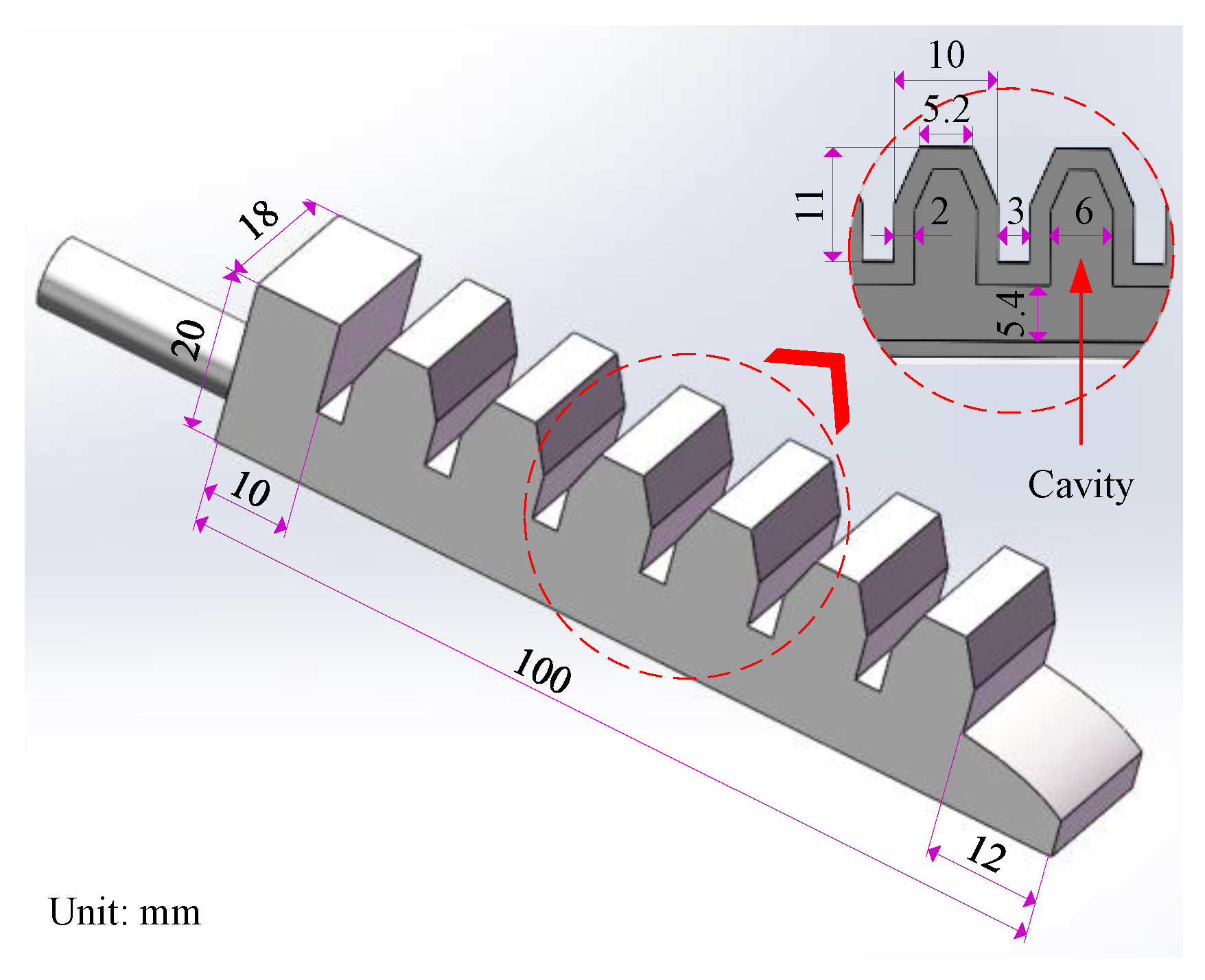
2. Structural Design and Manufacturing of SPG
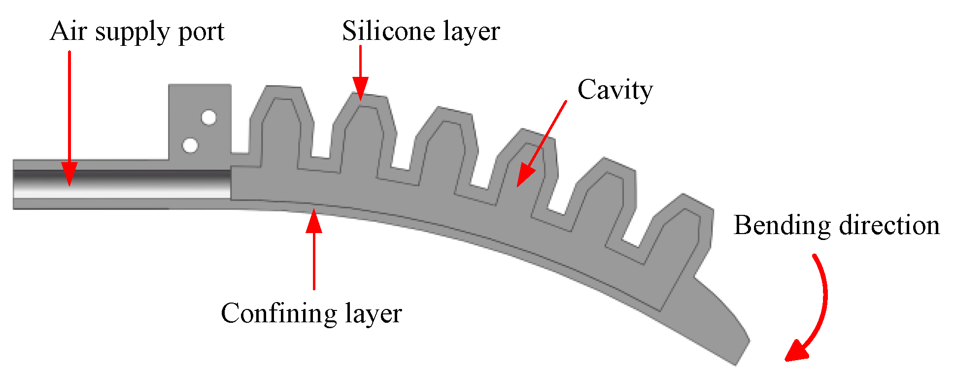
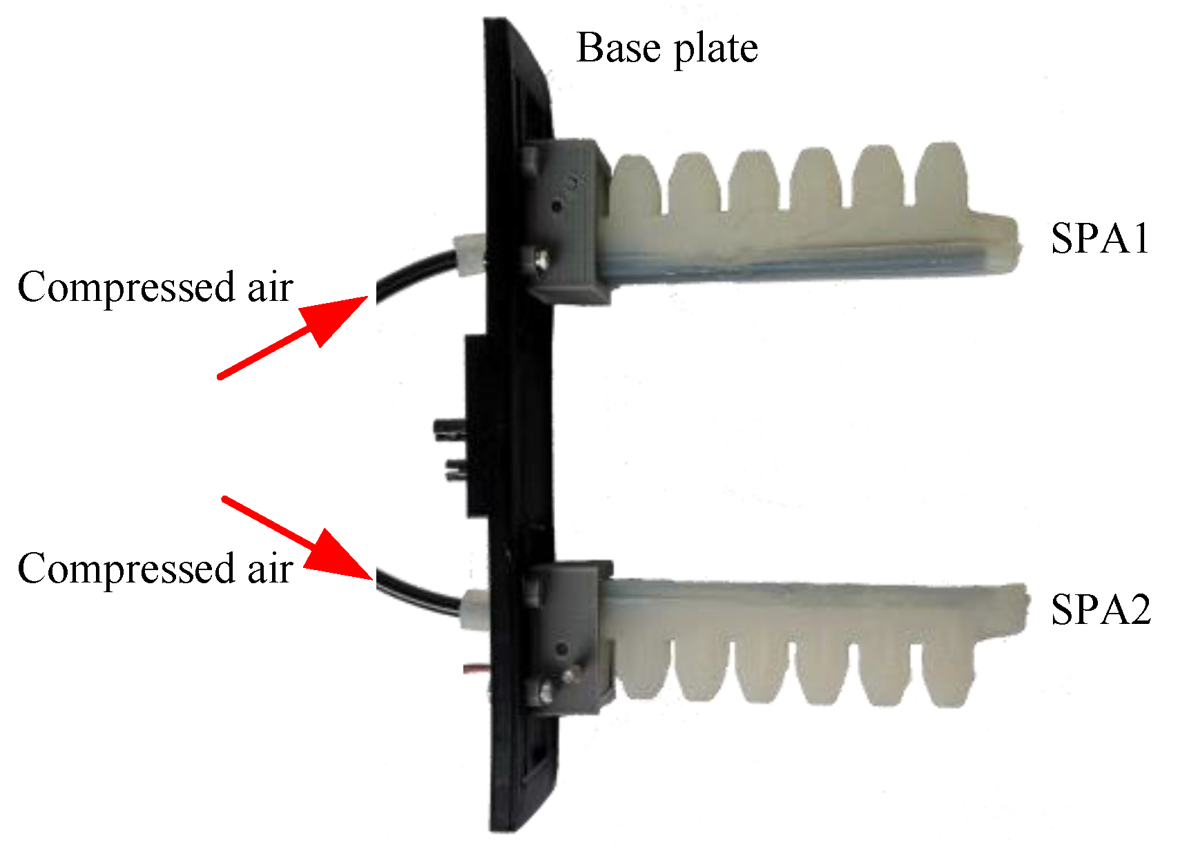
2.1. Design of SPA
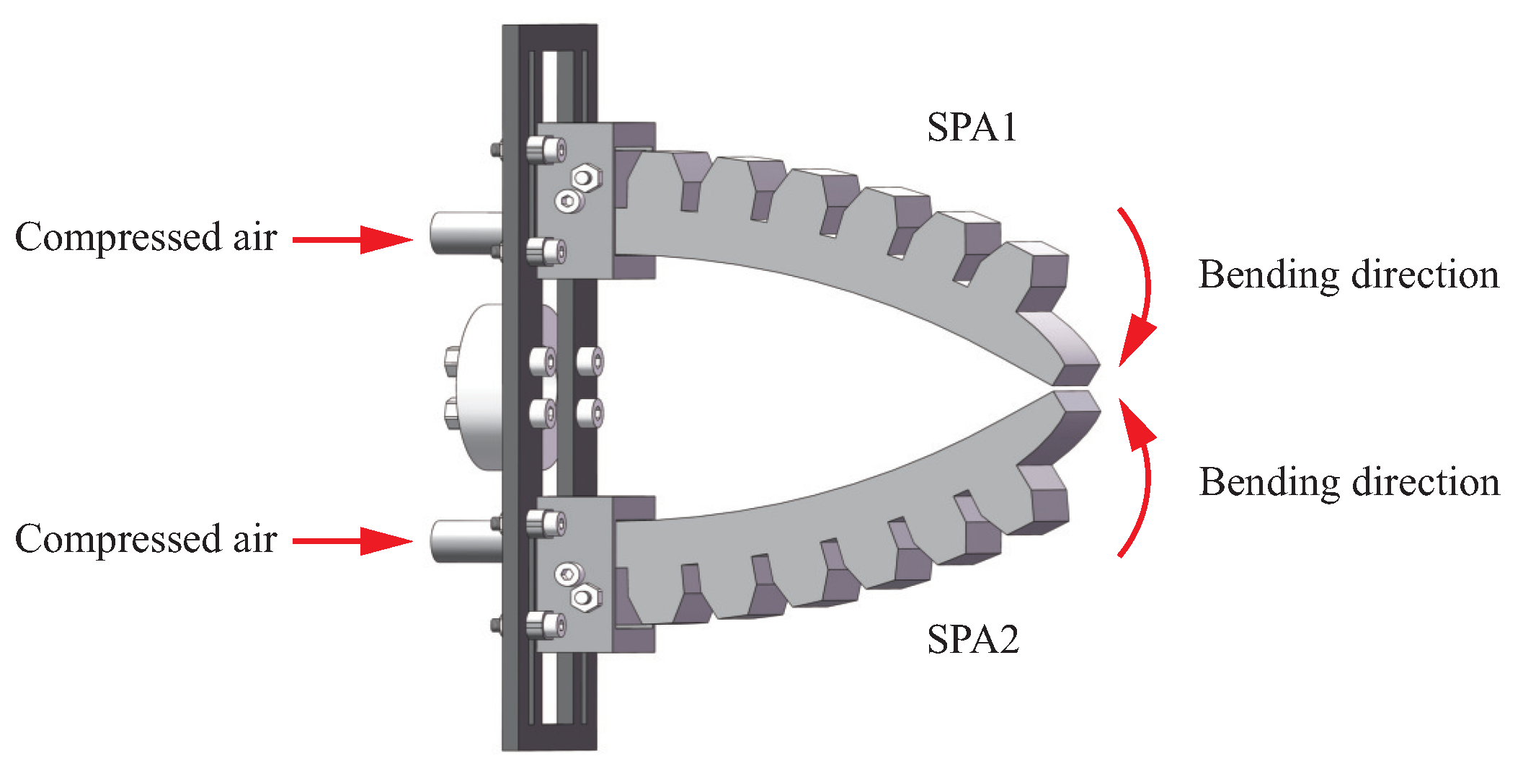
2.2. Design of SPG
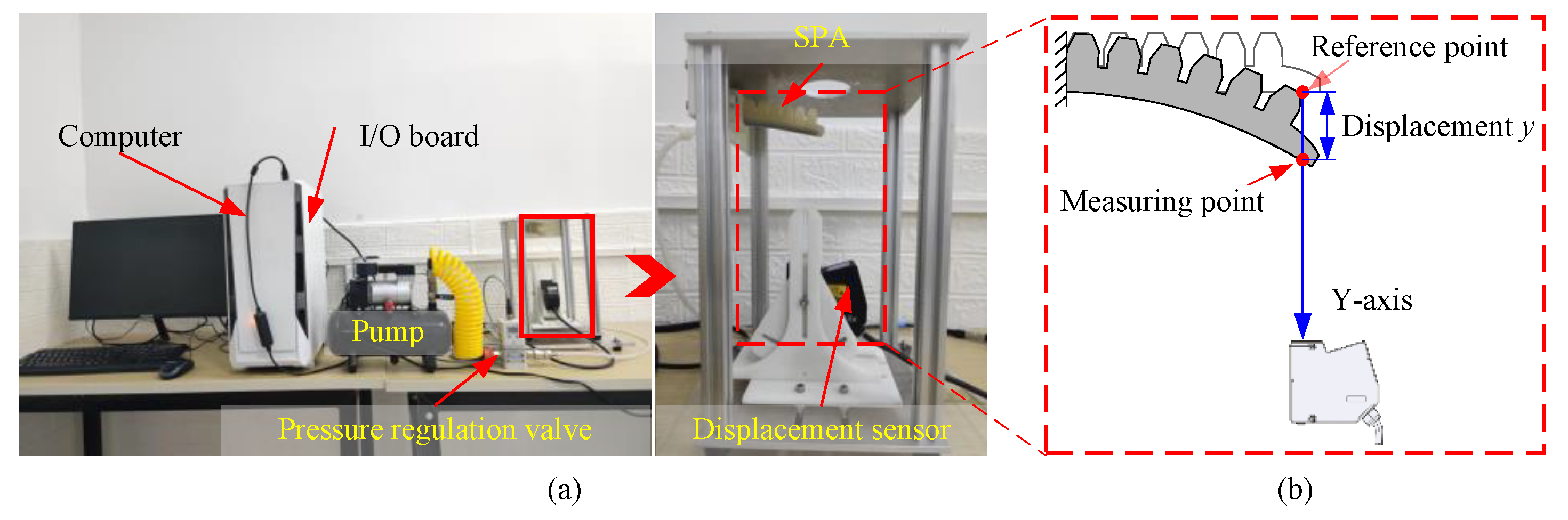
2.3. Experimental Testbench A
2.4. Experimental Testbench B
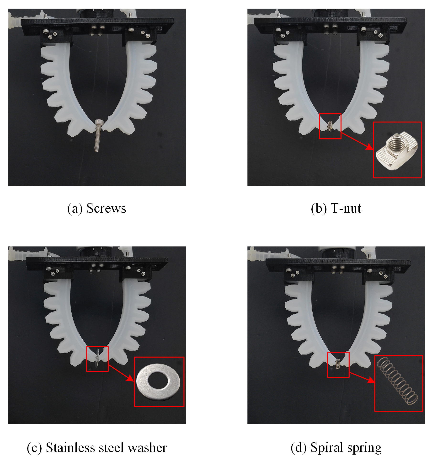
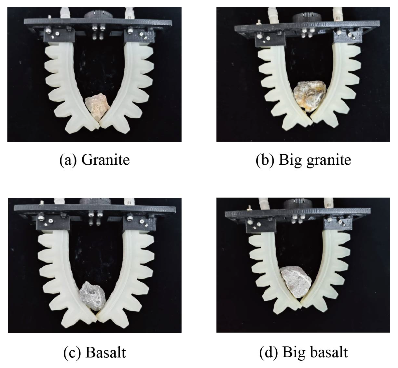
3. Gripping Experiments and Characteristic Analysis of SPG
4. Dynamic Modeling of SPA
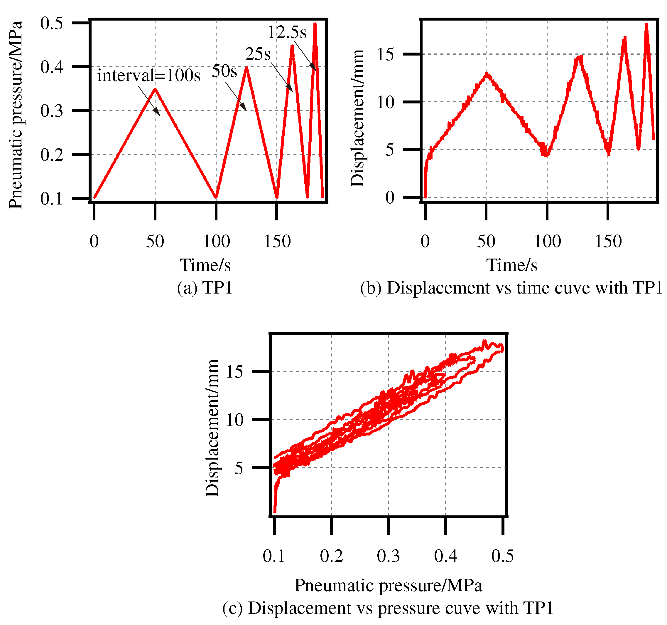
4.1. Dynamic Characteristics Analysis
- •
- Hysteresis characteristic: The output displacement vs. input pressure curve forms the hysteresis loops. In addition, the shapes of the hysteresis loops are amplitude-dependent and frequency-dependent.
- •
- Creep characteristic: The output displacement produces a drift along the application of the input pressure. In other words, the output displacement cannot return to its initial value when the input pressure backs to the initial value.
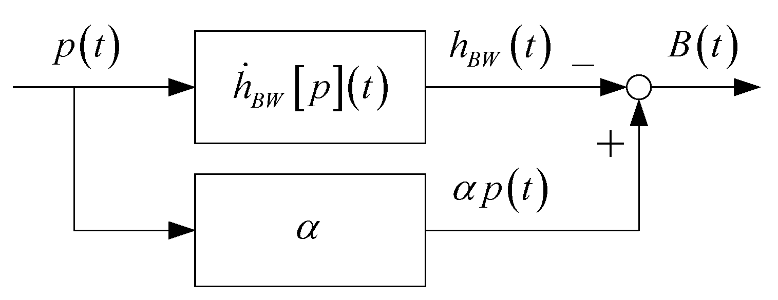
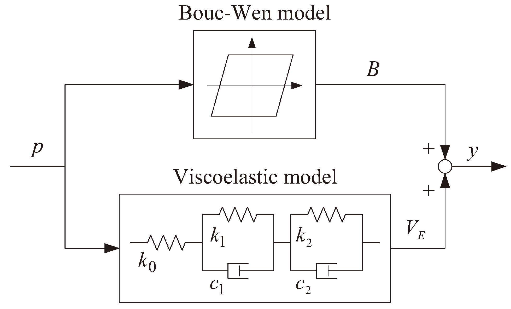
4.2. Dynamic Model
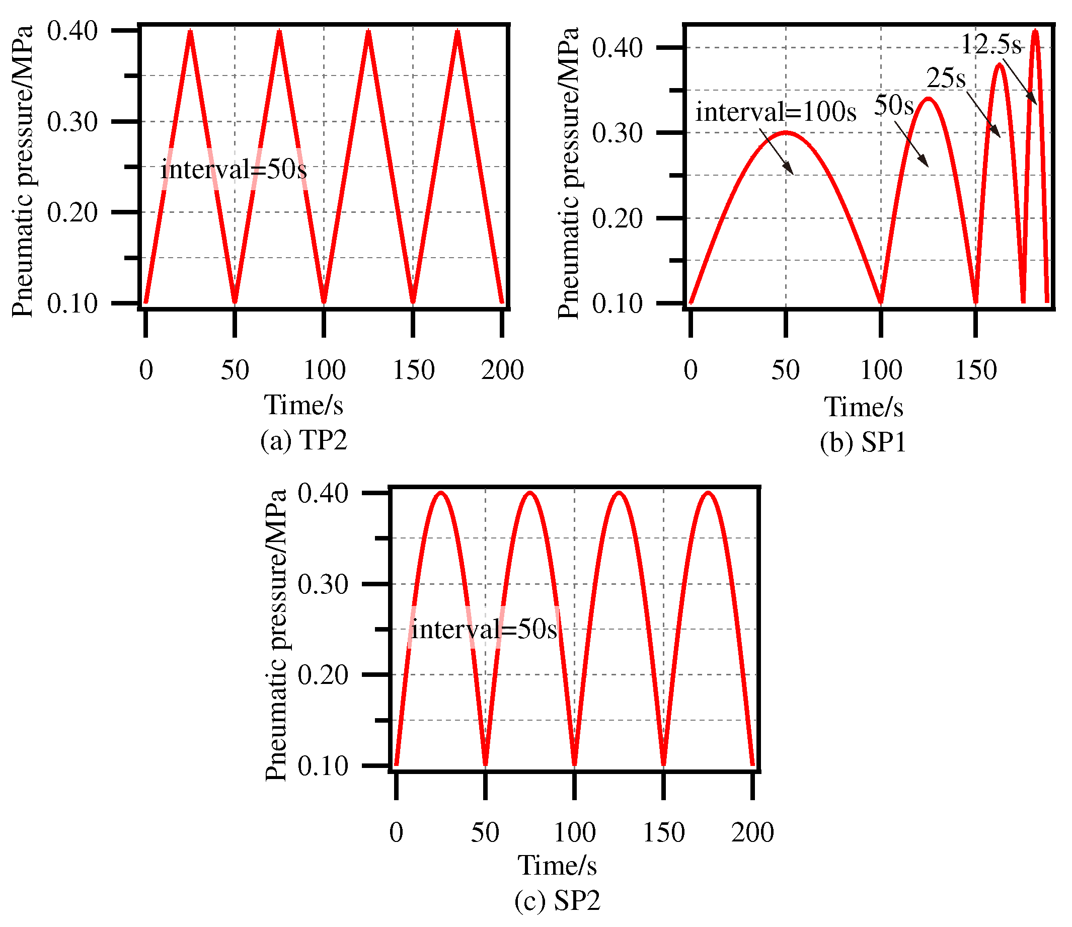
4.3. Identification of Dynamic Model of SPG
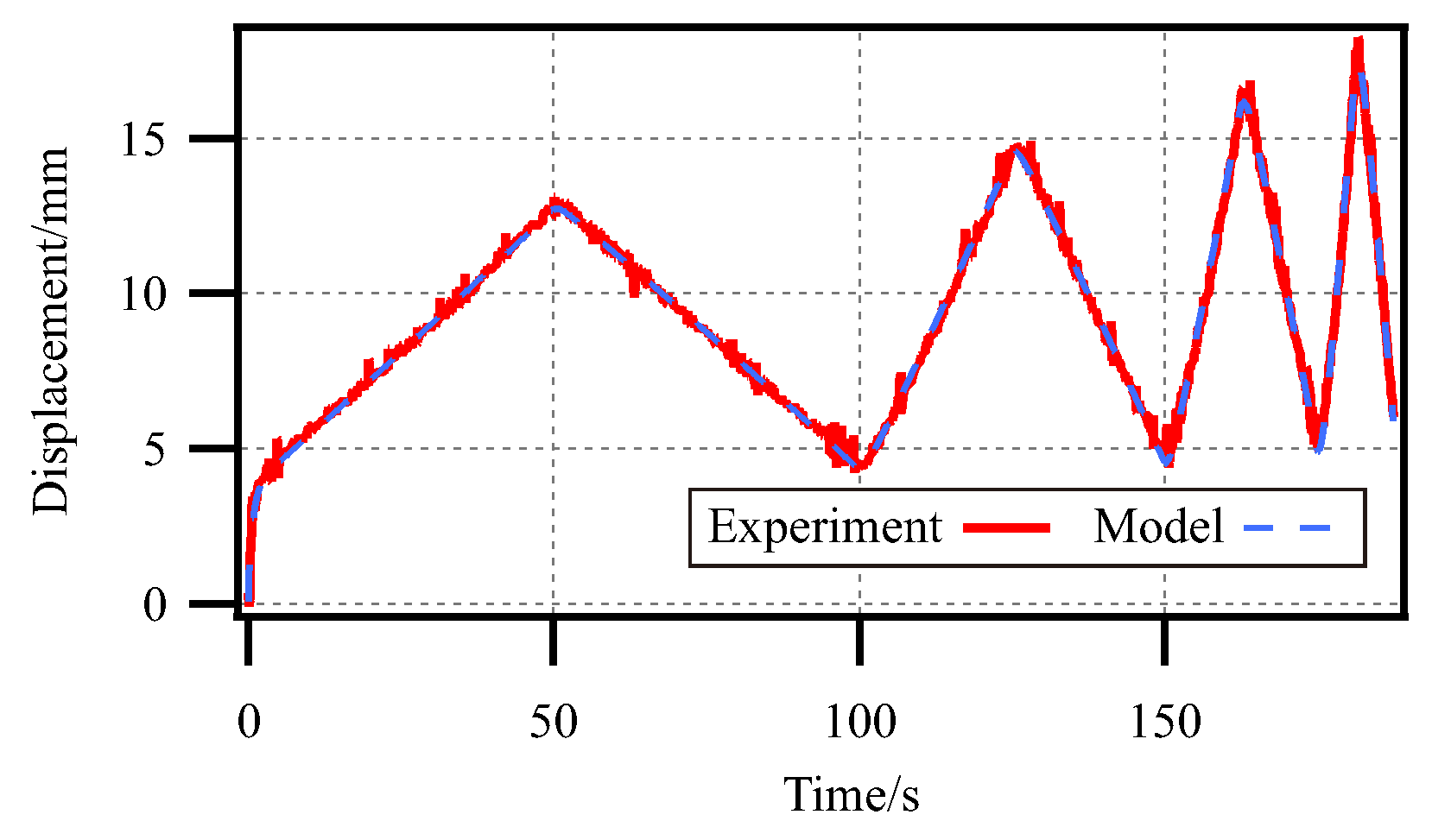
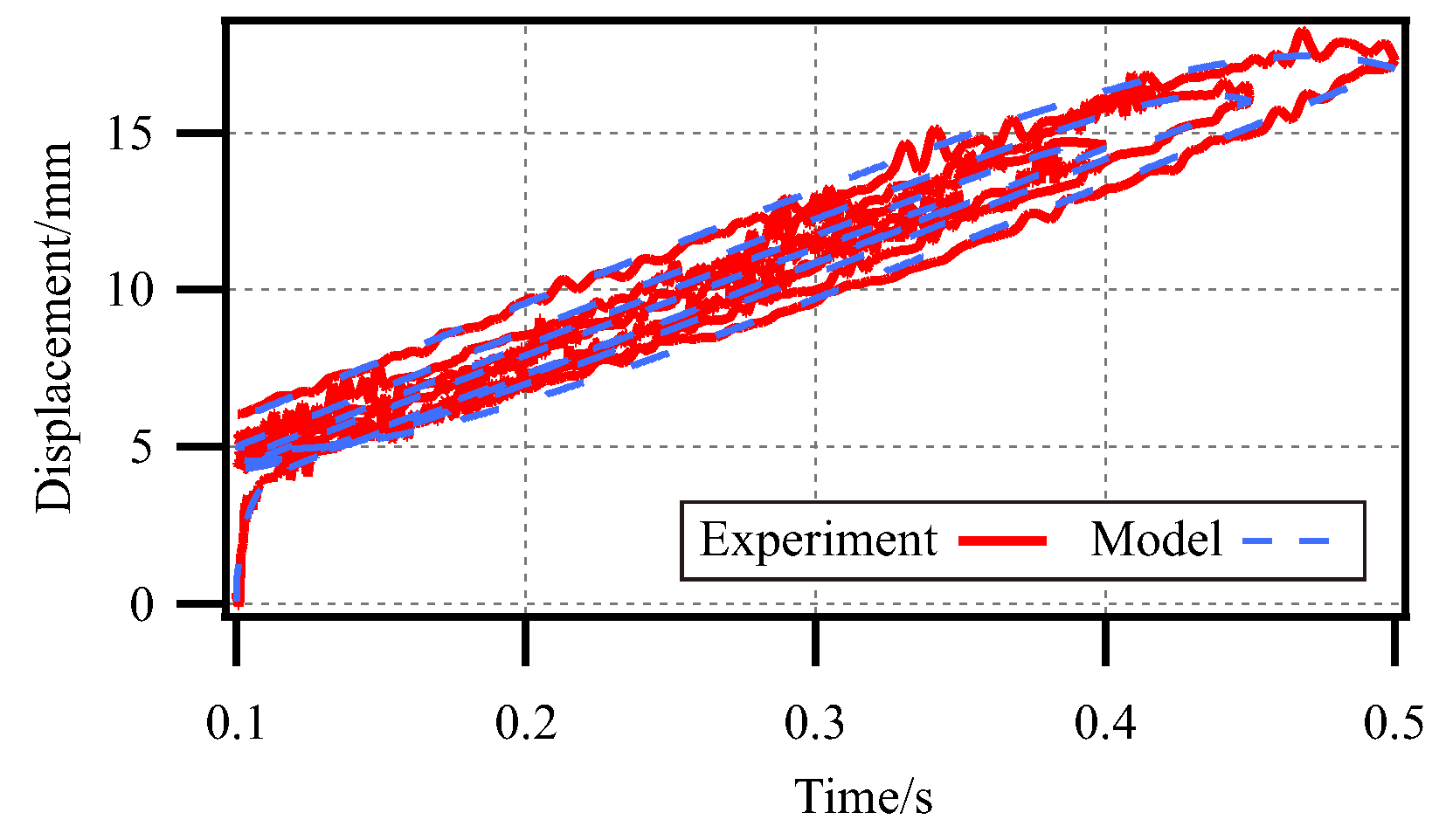
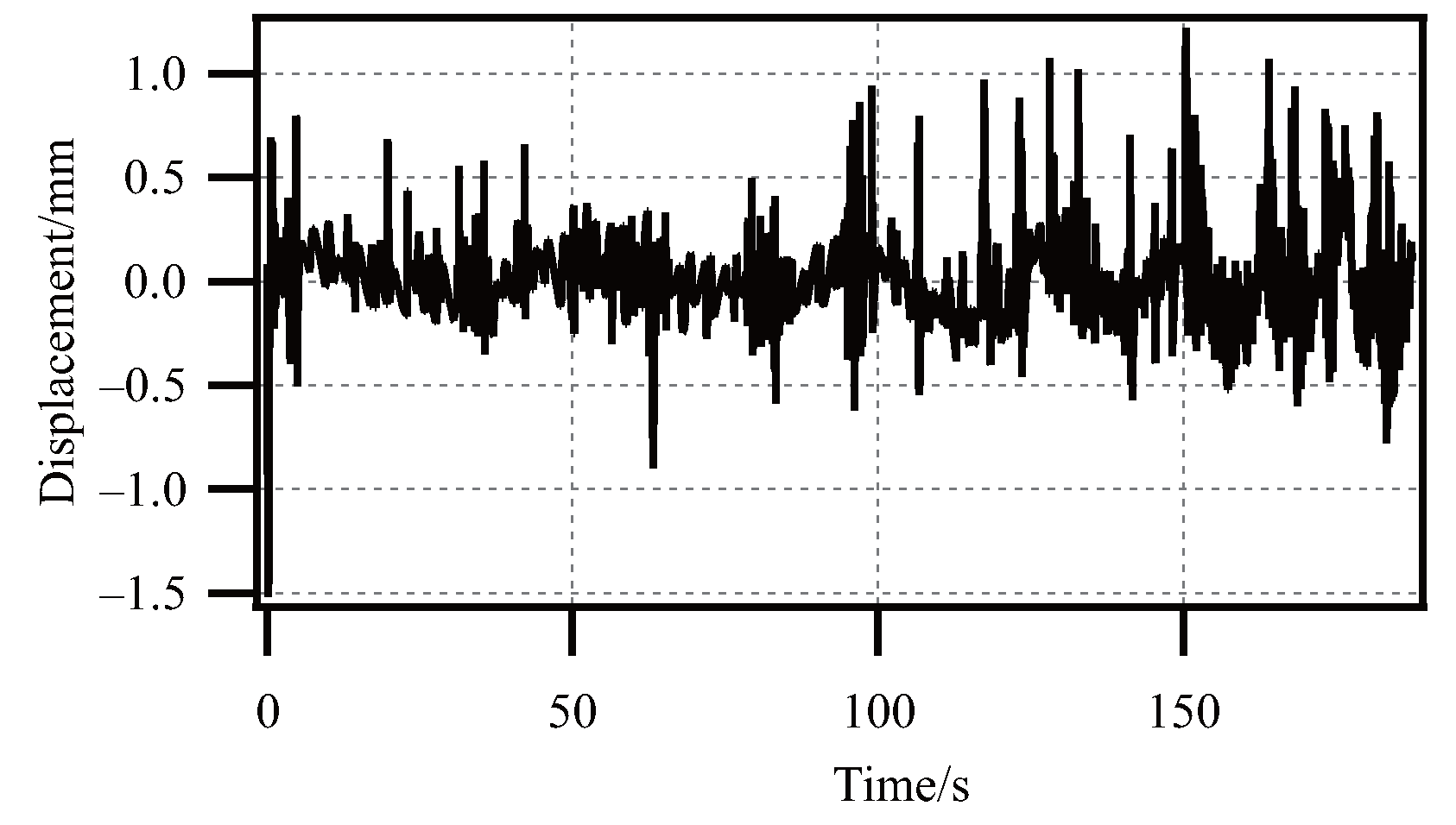
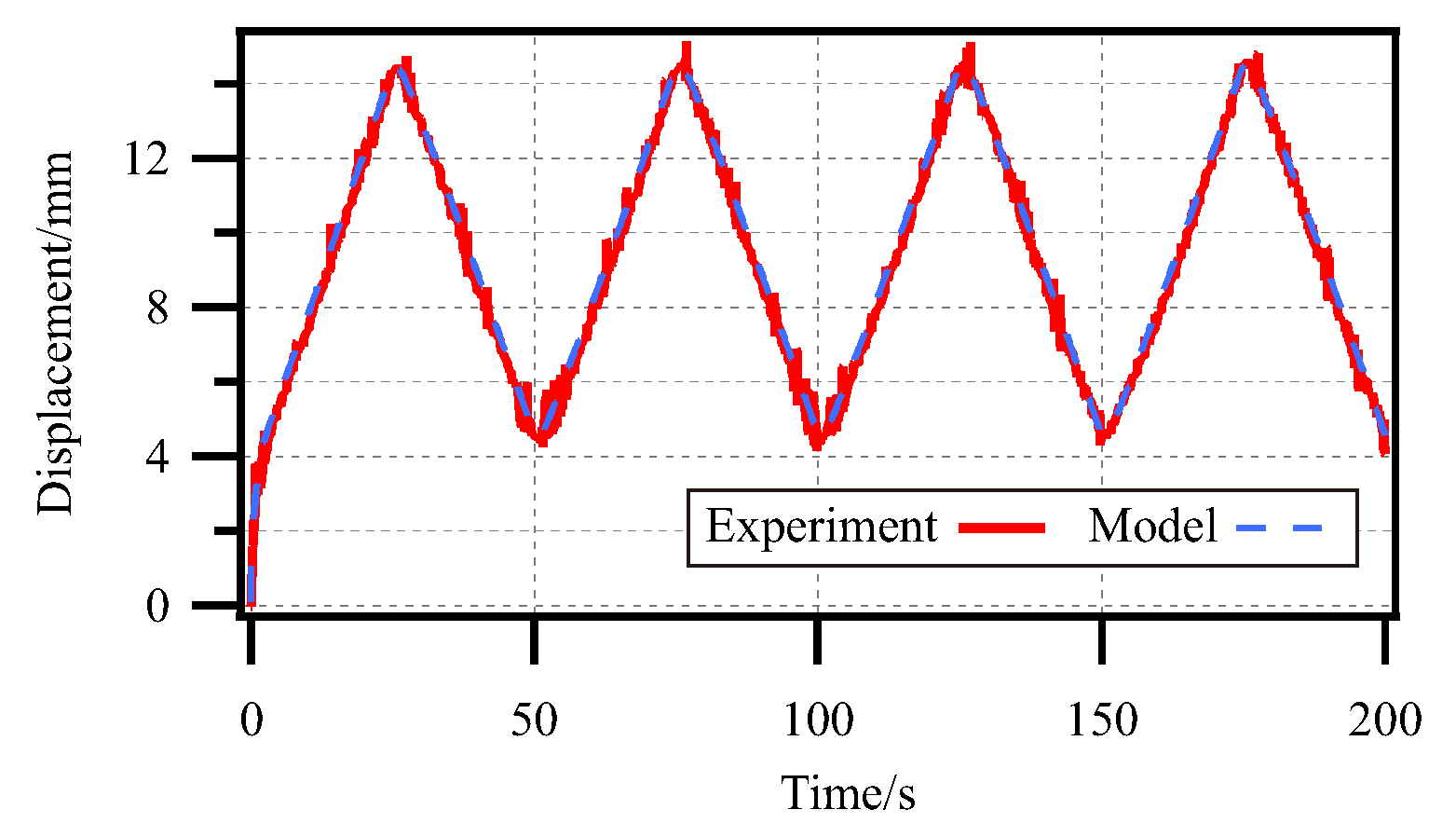
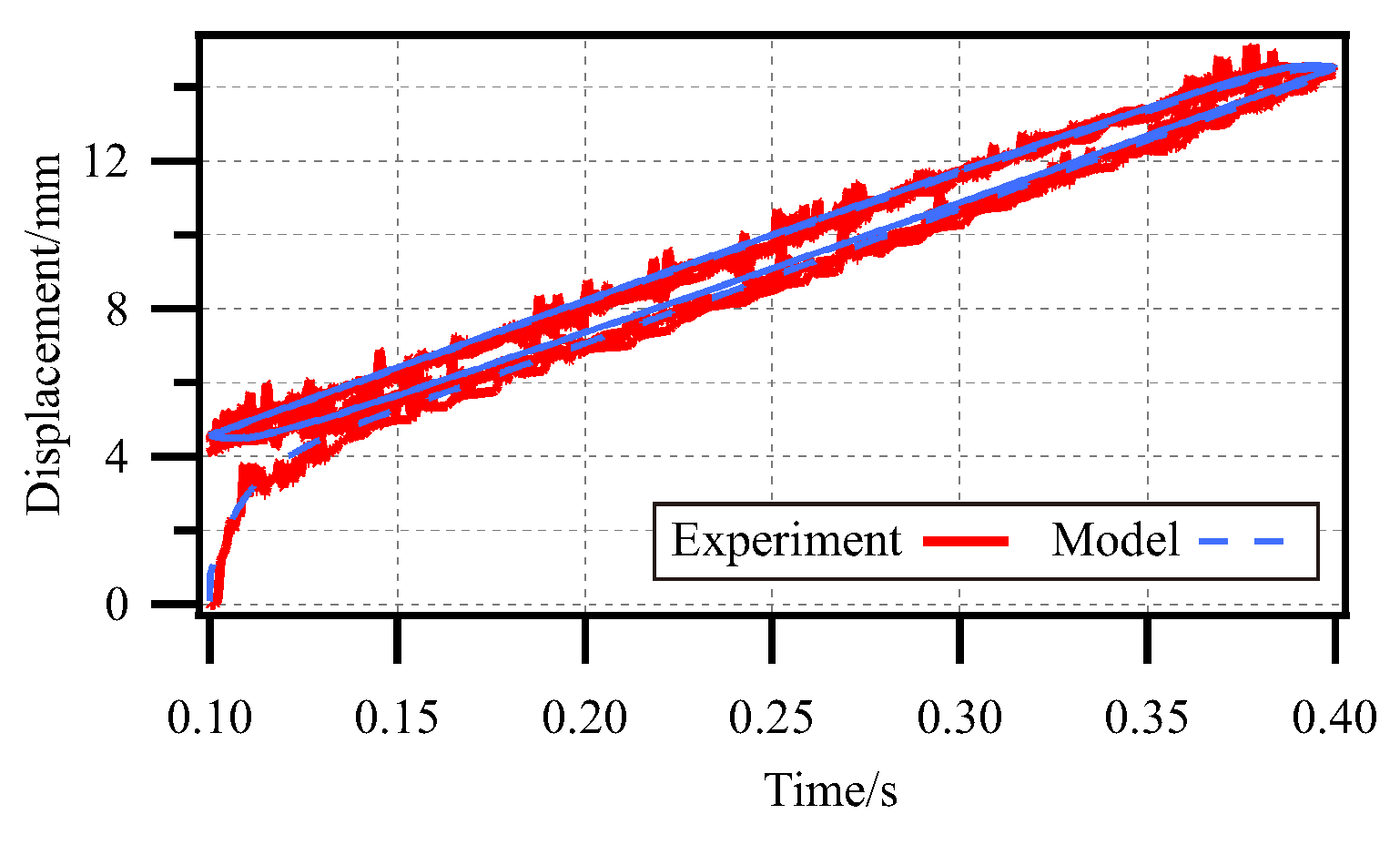
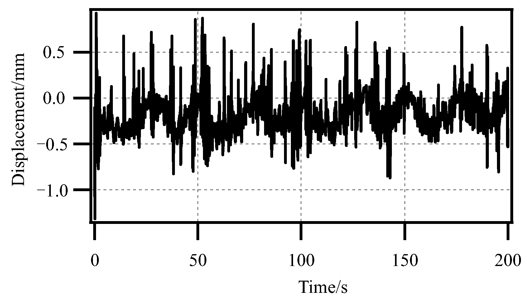
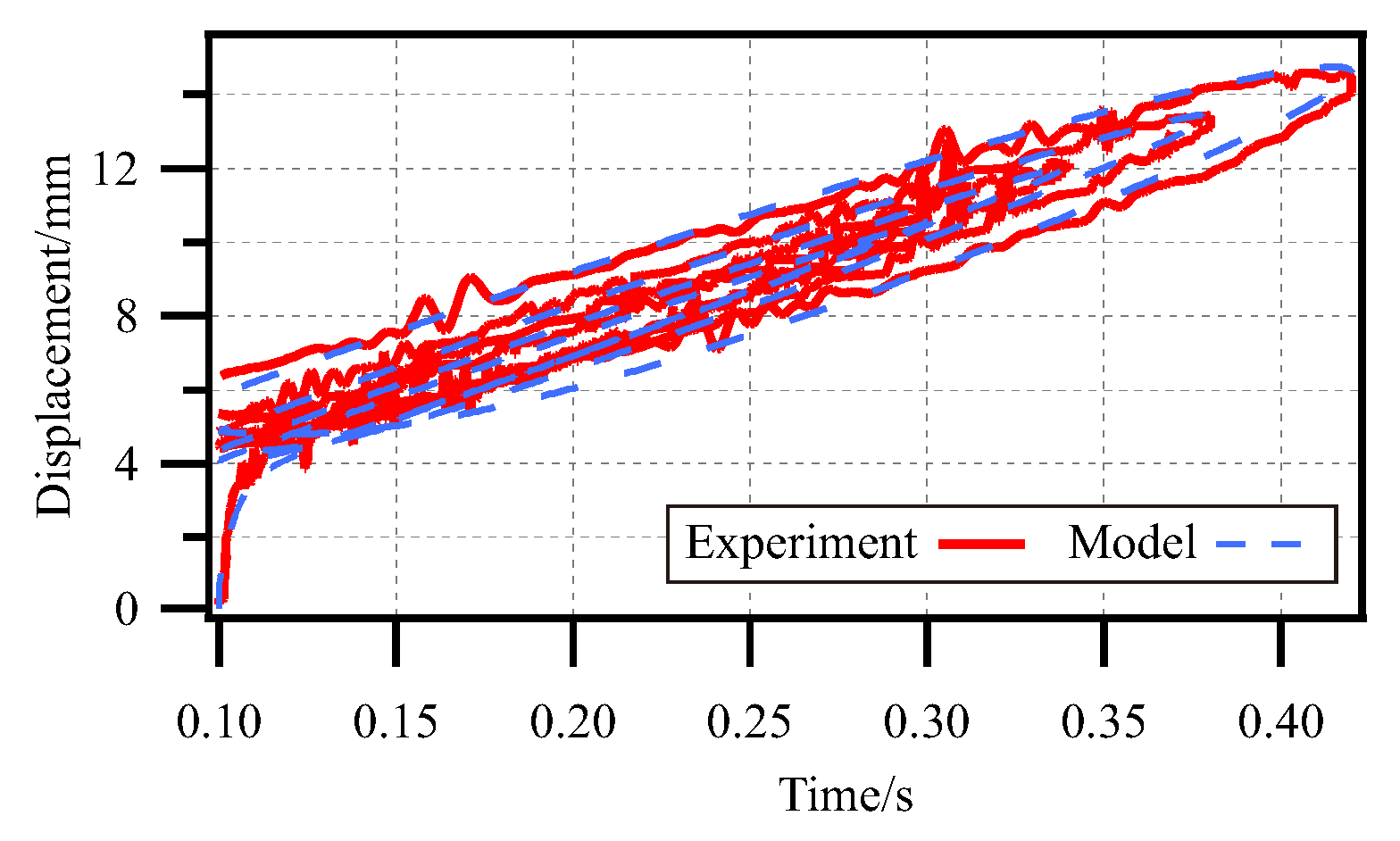
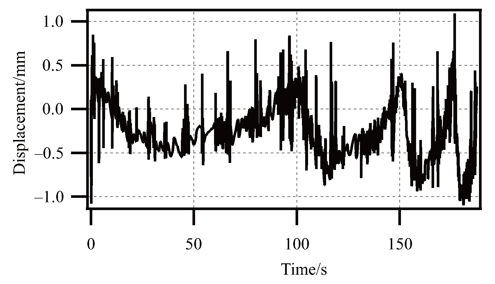
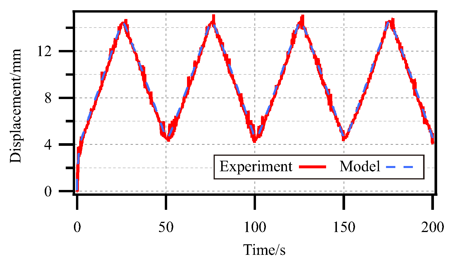
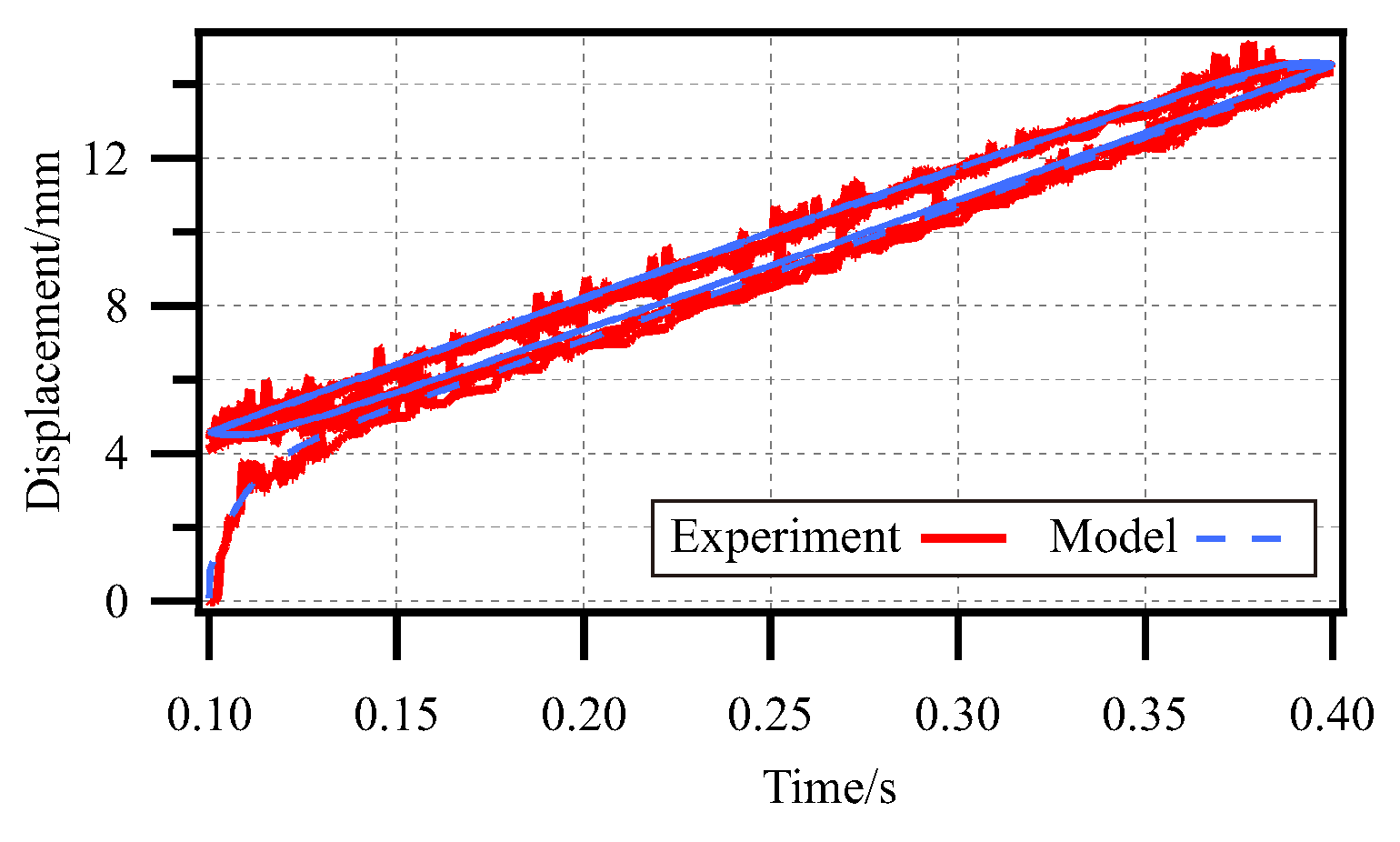
4.4. Validation of Dynamic Model of SPG
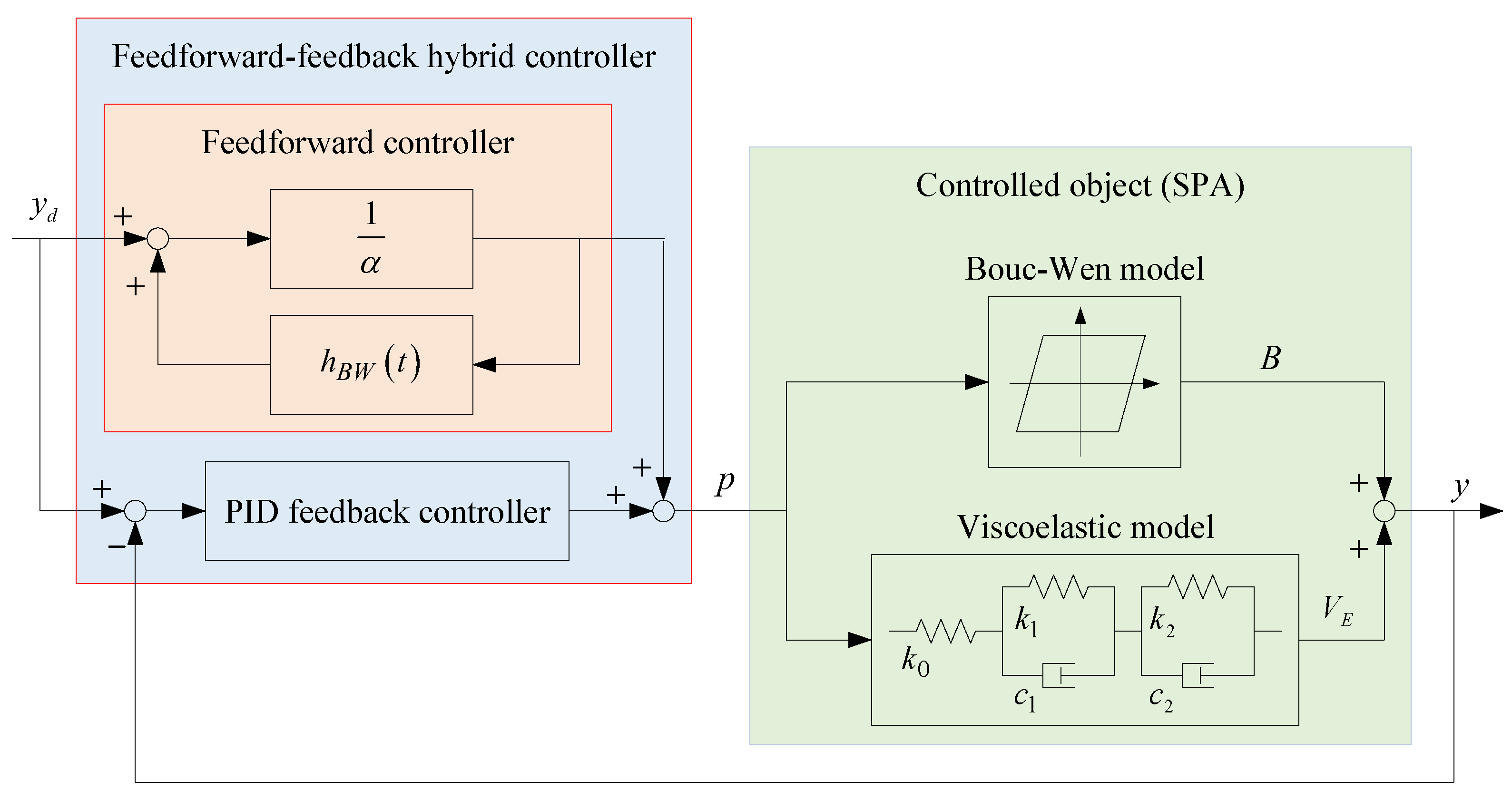
5. Hysteresis Inverse Compensation Control of the SPA
6. Conclusions
Author Contributions
Funding
Data Availability Statement
Conflicts of Interest
References
- Jordens, A.; Cheng, Y.P.; Waters, K.E. A review of the beneficiation of rare earth element bearing minerals. Miner. Eng. 2013, 41, 97–114. [Google Scholar] [CrossRef]
- Yang, X. Beneficiation studies of tungsten ores—A review. Miner. Eng. 2018, 125, 111–119. [Google Scholar] [CrossRef]
- Rus, D.; Tolley, M.T. Design, fabrication and control of soft robots. Nature 2015, 521, 467–475. [Google Scholar] [CrossRef]
- El-Atab, N.; Mishra, R.B.; Al-Modaf, F.; Joharji, L.; Alsharif, A.A.; Alamoudi, H.; Diaz, M.; Qaiser, N.; Hussain, M.M. Soft actuators for soft robotic applications: A review. Adv. Intell. Syst. 2020, 2, 2000128. [Google Scholar] [CrossRef]
- Han, W.B.; Ko, G.J.; Lee, K.G.; Kim, D.; Lee, J.H.; Yang, S.M.; Kim, D.J.; Shin, J.W.; Jang, T.M.; Han, S.; et al. Ultra-stretchable and biodegradable elastomers for soft, transient electronics. Nat. Commun. 2023, 14, 2263. [Google Scholar] [CrossRef]
- Li, G.R.; Chen, X.P.; Zhou, F.H.; Liang, Y.M.; Xiao, Y.H.; Cao, X.; Zhang, Z.; Zhang, M.Q.; Wu, B.S.; Yin, S.Y.; et al. Self-powered soft robot in the Mariana Trench. Nature 2021, 591, 66–71. [Google Scholar] [CrossRef]
- Chen, Y.F.; Zhao, H.C.; Mao, J.; Chirarattananon, P.; Helbling, E.F.; Hyun, N.s.P.; Clarke, D.R.; Wood, R.J. Controlled flight of a microrobot powered by soft artificial muscles. Nature 2019, 575, 324–329. [Google Scholar] [CrossRef]
- Xavier, M.S.; Tawk, C.D.; Zolfagharian, A.; Pinskier, J.; Howard, D.; Young, T.; Lai, J.; Harrison, S.M.; Yong, Y.K.; Bodaghi, M.; et al. Soft pneumatic actuators: A review of design, fabrication, modeling, sensing, control and applications. IEEE Access 2022, 10, 59442–59485. [Google Scholar] [CrossRef]
- Yuk, H.; Lin, S.; Ma, C.; Takaffoli, M.; Fang, N.X.; Zhao, X. Hydraulic hydrogel actuators and robots optically and sonically camouflaged in water. Nat. Commun. 2017, 8, 14230. [Google Scholar] [CrossRef]
- Shen, Z.; Chen, F.; Zhu, X.; Yong, K.T.; Gu, G. Stimuli-responsive functional materials for soft robotics. J. Mater. Chem. B 2020, 8, 8972–8991. [Google Scholar] [CrossRef]
- Nocentini, S.; Parmeggiani, C.; Martella, D.; Wiersma, D.S. Optically driven soft micro robotics. Adv. Opt. Mater. 2018, 6, 1800207. [Google Scholar] [CrossRef]
- Lendlein, A. Fabrication of reprogrammable shape-memory polymer actuators for robotics. Sci. Robot. 2018, 3, eaat9090. [Google Scholar] [CrossRef] [PubMed]
- Hu, W.; Lum, G.Z.; Mastrangeli, M.; Sitti, M. Small-scale soft-bodied robot with multimodal locomotion. Nature 2018, 554, 81–85. [Google Scholar] [CrossRef] [PubMed]
- Zatopa, A.; Walker, S.; Menguc, Y. Fully soft 3D-printed electroactive fluidic valve for soft hydraulic robots. Soft Robot. 2018, 5, 258–271. [Google Scholar] [CrossRef]
- Jones, T.J.; Jambon-Puillet, E.; Marthelot, J.; Brun, P.T. Bubble casting soft robotics. Nature 2021, 599, 229–233. [Google Scholar] [CrossRef]
- Tang, Y.; Chi, Y.; Sun, J.; Huang, T.H.; Maghsoudi, O.H.; Spence, A.; Zhao, J.; Su, H.; Yin, J. Leveraging elastic instabilities for amplified performance: Spine-inspired high-speed and high-force soft robots. Sci. Adv. 2020, 6, eaaz6912. [Google Scholar] [CrossRef]
- Baines, R.; Patiballa, S.K.; Booth, J.; Ramirez, L.; Sipple, T.; Garcia, A.; Fish, F.; Kramer-Bottiglio, R. Multi-environment robotic transitions through adaptive morphogenesis. Nature 2022, 610, 283–289. [Google Scholar] [CrossRef]
- Gai, L.J.; Huang, J.; Zong, X. Stiffness-Tunable Soft Bellows Actuators by Cross-Fiber Jamming Effect for Robust Grasping. IEEE/ASME Trans. Mechatronics 2023, 28, 2897–2907. [Google Scholar] [CrossRef]
- Terryn, S.; Brancart, J.; Lefeber, D.; Assche, G.V.; Vanderborght, B. Self-healing soft pneumatic robots. Sci. Robot. 2017, 2, eaan4268. [Google Scholar] [CrossRef]
- Moseley, P.; Florez, J.M.; Sonar, H.A.; Agarwal, G.; Curtin, W.; Paik, J. Modeling, design, and development of soft pneumatic actuators with finite element method. Adv. Eng. Mater. 2016, 18, 978–988. [Google Scholar] [CrossRef]
- Shen, X. Nonlinear model-based control of pneumatic artificial muscle servo systems. Control Eng. Pract. 2010, 18, 311–317. [Google Scholar] [CrossRef]
- Dao, Q.T.; Le, H.T.; Nguyen, M.L.; Do, T.H.; Duong, M.D. A Modified Bouc-Wen Model of Pneumatic Artificial Muscles in Antagonistic Configuration. In Proceedings of the 2020 International Conference on Advanced Mechatronic Systems, Hanoi, Vietnam, 10–13 December 2020; pp. 157–161. [Google Scholar]
- Xie, S.; Ren, G.; Wang, B. A modified asymmetric generalized Prandtl–Ishlinskii model for characterizing the irregular asymmetric hysteresis of self-made pneumatic muscle actuators. Mech. Mach. Theory 2020, 149, 103836. [Google Scholar] [CrossRef]
- Annakkage, U.; McLaren, P.; Dirks, E.; Jayasinghe, R.; Parker, A. A current transformer model based on the Jiles-Atherton theory of ferromagnetic hysteresis. IEEE Trans. Power Deliv. 2000, 15, 57–61. [Google Scholar] [CrossRef]
- Al Janaideh, M.; Rakheja, S.; Su, C.Y. An analytical generalized Prandtl–Ishlinskii model inversion for hysteresis compensation in micropositioning control. IEEE/ASME Trans. Mechatronics 2010, 16, 734–744. [Google Scholar] [CrossRef]
- Ismail, M.; Ikhouane, F.; Rodellar, J. The hysteresis Bouc-Wen model, a survey. Arch. Comput. Methods Eng. 2009, 16, 161–188. [Google Scholar] [CrossRef]


Disclaimer/Publisher’s Note: The statements, opinions and data contained in all publications are solely those of the individual author(s) and contributor(s) and not of MDPI and/or the editor(s). MDPI and/or the editor(s) disclaim responsibility for any injury to people or property resulting from any ideas, methods, instructions or products referred to in the content. |
© 2025 by the authors. Licensee MDPI, Basel, Switzerland. This article is an open access article distributed under the terms and conditions of the Creative Commons Attribution (CC BY) license (https://creativecommons.org/licenses/by/4.0/).
Share and Cite
Zhang, Y.; Lu, J.; Huang, Z.; Feng, B. Modeling and Hysteresis Inverse Compensation Control of Soft Pneumatic Gripper for Gripping Phosphorites. Actuators 2025, 14, 193. https://doi.org/10.3390/act14040193
Zhang Y, Lu J, Huang Z, Feng B. Modeling and Hysteresis Inverse Compensation Control of Soft Pneumatic Gripper for Gripping Phosphorites. Actuators. 2025; 14(4):193. https://doi.org/10.3390/act14040193
Chicago/Turabian StyleZhang, Yang, Junjie Lu, Zixin Huang, and Bing Feng. 2025. "Modeling and Hysteresis Inverse Compensation Control of Soft Pneumatic Gripper for Gripping Phosphorites" Actuators 14, no. 4: 193. https://doi.org/10.3390/act14040193
APA StyleZhang, Y., Lu, J., Huang, Z., & Feng, B. (2025). Modeling and Hysteresis Inverse Compensation Control of Soft Pneumatic Gripper for Gripping Phosphorites. Actuators, 14(4), 193. https://doi.org/10.3390/act14040193