Article

A Low-Cost Prototype of a Soft–Rigid Hybrid Pneumatic Anthropomorphic Gripper for Testing Tactile Sensor Arrays

by
Rafał Andrejczuk
1,*,
Moritz Scharff
2,
Junhao Ni
2,
Andreas Richter
1 and
Ernst-Friedrich Markus Vorrath
1,2
1
Institute of Semiconductors and Microsystems, Technische Universität Dresden, 01069 Dresden, Germany
2
PowerON Group, Auckland 1010, New Zealand
*
Author to whom correspondence should be addressed.
Actuators 2025, 14(5), 252; https://doi.org/10.3390/act14050252
Submission received: 8 April 2025 / Revised: 10 May 2025 / Accepted: 14 May 2025 / Published: 17 May 2025

Abstract

:
Soft anthropomorphic robotic grippers are attractive because of their inherent compliance, allowing them to adapt to the shape of grasped objects and the overload protection needed for safe human–robot interaction or gripping delicate objects with sophisticated control. The anthropomorphic design allows the gripper to benefit from the biological evolution of the human hand to create a multi-functional robotic end effector. Entirely soft grippers could be more efficient because they yield under high loads. A trending solution is a hybrid gripper combining soft and rigid elements. This work describes a prototype of an anthropomorphic, underactuated five-finger gripper with a direct pneumatic drive from soft bending actuators and an integrated resistive tactile sensor array. It is a hybrid construction with soft robotic structures and rigid skeletal elements, which reinforce the body, focus the direction of the actuator’s movement, and make the finger joints follow the forward kinematics. The hand is equipped with a resistive tactile dielectric elastomer sensor array that directly triggers the hand’s actuation in the sense of reflexes. The hand can execute precision grips with two and three fingers, as well as lateral grip and strong grip types. The softness of the actuation allows the finger to adapt to the shape of the objects.

1. Introduction

The human hand is a result of biological evolution, which is responsible for designing a dexterous, multi-functional tool over several million years. Its structure enables precision, power, and compliance, and thus, providing a role model for a gripper design that we are familiar with from our everyday life [1]. Such anthropomorphic grippers can be used as prostheses; are compatible with a human-oriented environment, like ergonomic tools; or can be intuitively teleoperated by humans, e.g., operated in hazardous environments without risking one’s health [2].
Throughout the last century, Piazza et al. have reported on the development of over two hundred robotic hands of different types [3]. Robotic hand designs vary widely across the spectrum from rigid to soft, with hybrid approaches gaining traction in recent years. Notable examples of classic hand grippers made of rigid machined part and characterized by precision and predictable movements [4] are the SpaceHand [4], the Shadow Dexterous Hand [5], or the Schunk SVH [6]. The SpaceHand is a space-qualified robotic hand that is able to work in harsh conditions to assist astronauts [4]. The Shadow Dexterous Hand is a tendon-driven, five-fingered hand that is claimed to be the most advanced robotic hand available, with the possibility to equip it with tactile sensing [5]. The Schunk SVH is a highly complex robotic hand with nine drives and gear transmission [6]. Others followed an approach of replicating essential biomechanical elements, such as bones, tendons, routing, ligaments, or joints, and developed a highly biomimetic anthropomorphic robotic hand [7]. The concept of so-called hand synergies has been successfully engineered by others, leading to a drastic reduction in the number of actuators. As a result, The Pisa/IIT SoftHand 2 has been developed, featuring only two drives while demonstrating impressive in-hand manipulations [8]. Deimel and Brock have developed the RBO Hand 2, a fully compliant soft robotic pneumatically driven hand capable of dexterous grasping. It achieves 94% of the postures from the human grasp taxonomy and scores 7 out of 8 points in the Kapandji test (thumb test) [9].
In a world of the increasing importance of human–machine interaction and collaboration, designs like the Schunk SVH or Shadow Dexterous Hand lack inherent compliance and overload protection, and thus, do not assure safety. For this reason, the field of soft pneumatic robotics became a dynamically blooming field generating compliant, life-like solutions, e.g., RBO Hand 2. Unfortunately, on account of the softness, they are usually weaker in producing force and lack mechanical support. This can be solved globally or locally using stiffer silicones or rigid parts. Such soft–rigid hybrid gripper approaches have been developed and studied.
Nemoto et al. reported a lightweight prosthesis driven by curved pneumatic artificial muscles inserted into a realistic plastic hand [10]. Very similarly, Fras and Althoefer manufactured a fully compliant robotic hand driven by linear pneumatic actuators placed in the fingers of a one-part cast biomimetic hand, which directs linear motion into bending [11]. Chen et al. presented a robotic finger inspired by lobsters that comprises rigid and soft components. An inflatable hose is enclosed in multiple, rotatably connected rigid shells, which only allow for bending [12]. Galloway et al. programmed the bending radius and bending axis of a fiber-reinforced soft-bending actuator using a sleeve and fiber-reinforced laminate [13]. Gafer et al. developed a soft–rigid Quad-Spatula Gripper for food handling with a passively compliant structure and spatula-shaped interlocking fingertips [14]. Zhu et al. introduced a two-fingered soft–rigid gripper, drawing inspiration from the human metacarpophalangeal (MCP) joint [15]. It comprises eight independent muscles (four for each finger) and features lateral compliance for in-hand manipulation. The gripper incorporates hinge joints, resulting in conventional kinematics. Godaba et al. designed a tendon-driven two-fingered gripper consisting of pneumatic flexure hinges. The stiffness of these joints can be controlled with pressure, thus allowing different shapes of the finger [16].
A research gap remains in the development of low-cost, soft–rigid hybrid robotic hands that combine mechanical simplicity, modularity, and ease of tactile sensor deployment on non-deforming surfaces, while also supporting accessible manufacturing techniques and maintaining compliance. Existing rigid hands typically lack inherent compliance, as they are designed for precision and power. The prices for such commercial solutions can easily reach five-digit figures in USD. Tendon-driven hands often exhibit structural complexity due to low-friction cable routing, pulleys, and related mechanisms. Biomimetic approaches—such as those by Xu [7] and Faudzi [17], and involving anatomically correct testbed (ACT) hands [18]—aim to replicate human hand anatomy by incorporating ligaments or preserving specialized geometries, which further increases the mechanical complexity. Zhang made notable progress by simplifying joint geometries while preserving dexterity; however, the resulting design remains mechanically intricate [19]. Underactuated designs, like the Pisa/IIT SoftHand and Li’s open-source antagonistic tendon-driven hand, simplify control through concepts such as adaptive synergies, yet introduce complex transmission mechanisms [8,20]. Fully soft hands, such as the RBO Hand 2, deform internally, making them unsuitable for reliable tactile array testing, as unintentional sensor activation can occur [9]. Some designs have adopted principles similar to ours. For example, Zhang’s fully 3D-printed hybrid hand is notably simple but relies on multi-material printing, is limited to low-pressure actuation (16 kPa), and is not open source [21]. Zhu’s design also shares conceptual similarities, using discrete joints that support tactile sensor integration and a pneumatic direct drive for simplified construction. However, it is also closed source and achieves only 60° of joint flexion [15]. Xu introduced a conceptually similar hand made entirely from silicone, incorporating MCP joints and achieving 90° joint bending. However, it is fully soft, and thus, not ideal for sensor integration, and it also lacks open-source accessibility [22]. Recent open-source efforts, such as the DexHand [23], ORCA Hand [24], and LEAP Hand [25], have advanced the affordability and replicability. Nevertheless, most of these remain tendon- or motor-driven, and therefore, retain mechanical complexity and limited compliance. In contrast, our work focuses on a mechanically simpler solution. Lobster-inspired actuators, such as those by Chen, offer discrete joint-like sections but suffer from limited passive extension due to their rigid shells and rely on multiple joints rather than a few human-like segments [12]. Similarly, Galloway’s fiber-reinforced actuators [13] support programmable curvature but require high pressures (∼400 kPa) to achieve 90° bending and do not follow simple forward kinematics.
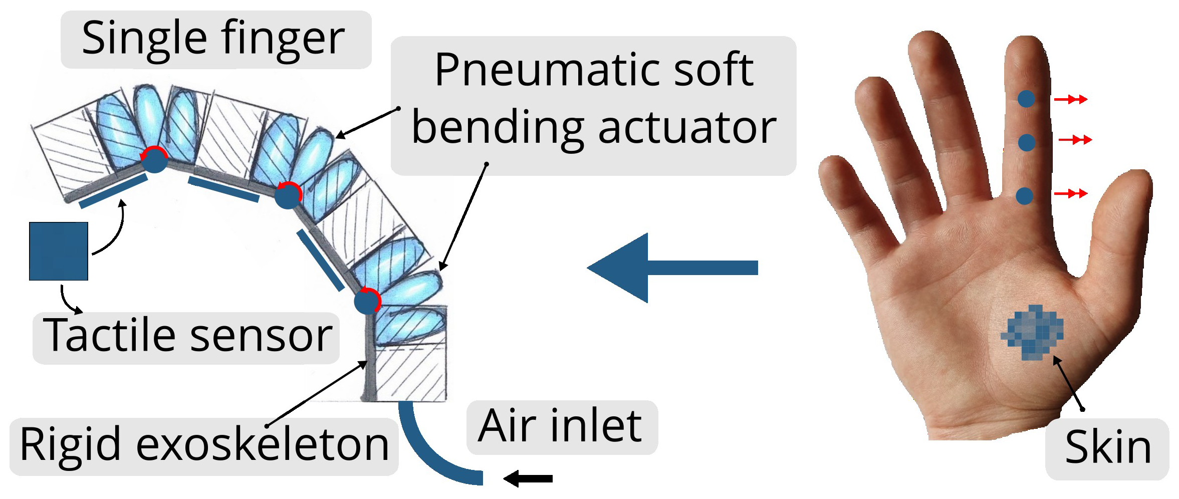
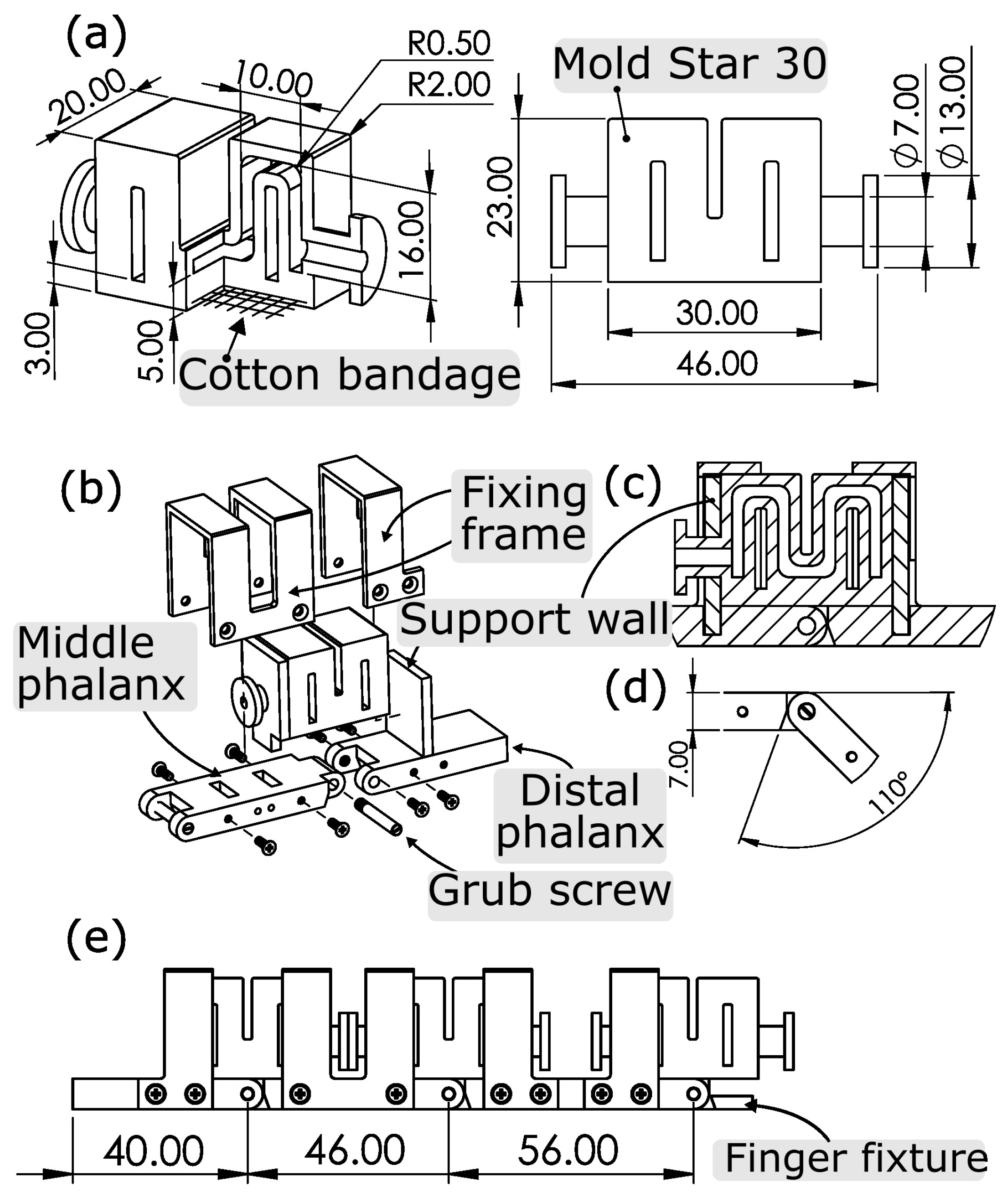
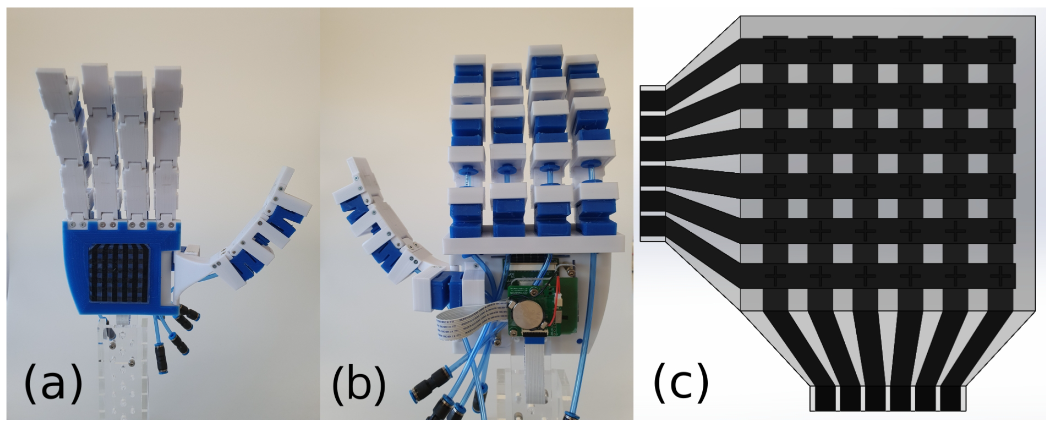
In this paper, we report a low-cost do-it-yourself (DIY) prototype of a soft–rigid hybrid anthropomorphic gripper. The five-fingered hand can be manufactured using fused deposition modeling (FDM) and silicone molding methods. As one of the first testing platforms for PowerON’s resistive tactile sensors, the robotic hand has big spaces on the finger links and on the palm of the hand to accommodate the sensors. These rigid skeletal elements connected with hinge joints give mechanical support, follow forward kinematics, and focus the movement of the pneumatic soft bending actuators, which directly drive the robotic hand. Furthermore, the rigidity will prevent deformation of the finger links, and thus, unintended activation of the sensor. In the first step, we only integrated the tactile sensor array in the palm of the hand and demonstrated position recognition of an object and reflexive features, such as catching a falling object. Due to the compressibility of pneumatic soft bending actuators, we were able to simplify the control system by reducing the number of pneumatic lines while maintaining the joint’s adaptivity to grasped objects. We propose a mechanical model of a single finger for future control, which can be extended further for complete hand control. We demonstrate the hand’s capability to perform precision grips using both two and three fingers with lateral and strong grip types. We present comprehensive insights into the gripper’s design and manufacturing process. Additionally, we report on conducted experimental investigations involving both individual joints and the hand as a whole. Moreover, we provide a description of our mobile five-channel pneumatic platform and current control schematics. Finally, we share CAD models of a single actuated joint that serve as building blocks and toolkit components for constructing various types of robotic structures, including human-like grippers, two-fingered grippers, or even terrestrial robots.
This paper addresses the lack of accessible, modular, and sensor-ready soft robotic platforms that combine compliance, mechanical robustness, simplicity, and practical usability. While many advanced robotic hands exist, they are often prohibitively expensive, difficult to modify or build due to closed-source designs, and do not provide suitable surfaces for integrating tactile sensors. We propose a low-cost, modular, soft–rigid hybrid joint design that follows simple forward kinematics and is manufactured using accessible techniques, such as FDM printing and silicone molding. The rigid skeleton provides mechanical support, guides the actuator motion, and offers integration space for tactile sensors while effectively isolating them from actuator deformation and unintended activation. The soft actuators, in turn, ensure adaptive and compliant interaction with the environment. The novelty of our work lies in the unique combination of affordability, a straightforward hybrid mechanical design, simplified pneumatic control, and sensor-compatible architecture, offering a practical and customizable gripper for research, education, and real-world applications.

2. Concept of the Anthropomorphic Soft–Rigid Hybrid Gripper

One of the primary considerations is the combination of skeletal reinforcing structures and soft pneumatic actuators or vice versa. A constraint is to be exerted through the skeleton on the actuator to block all degrees of freedom and parasitic movements except the desired one. For this purpose, elongated, cuboidal plastic elements are connected with a hinge joint to create a finger and correspond to phalanges in the human hand. On the structure’s back, as shown in Figure 1, a separate pneumatic soft bending actuator is placed on each joint instead of one actuator along the hole finger because bending occurs only at the location of the joint. Actuators are constrained with frames and support walls to the exoskeleton to enable torque transfer when inflated with compressed air. Flat, rigid phalanges are chosen because they enable the easy placement of tactile sensor arrays and decouple them from soft pneumatic actuators.
Since the finger design has defined bending points, the actuator should be able to generate a bending radius as small as possible and a deflection of at least 90°. At the same time, it should be relatively short, taking up as little space as possible so that the lengths of the phalanges are not too influenced. The anthropomorphic robotic gripper consists of four equal fingers and a fifth modified thumb. From five pressure-controlled channels in our control platform, two are assigned to the thumb to ensure flexion and opposition, one for the little finger and ring finger together, and a separate channel for each remaining finger. Even though the finger joints move simultaneously, they can adapt depending on the gripped object due to the compressibility of soft pneumatic actuators. The inner gripper surfaces are planned to be compliant by placing soft pads.

3. Materials and Methods

3.1. Pneumatic Soft Bending Actuator

The soft pneumatic bending actuator is a shortened version of Lotfiani’s actuator inspired by the curled-up body of a radiated rat snake and characterized by a fast speed and heavy load [26]. Even a short segment like this in Figure 2a shows a displacement of about 90° at 60 kPa, which is similar to the rotation range of human hand joints and agrees with our concept. Moreover, it achieves a small bending radius, which should be suitable for cooperation with the hinge joint. Lotfiani’s actuator, which is two and a half times longer than the one depicted in Figure 2a, can generate a force on the tip of 22 N at 100 kPa and lift a load of 417 g at a pressure of 105 kPa to full deflection [26]. The excellent performance of this actuator led to the adoption of all dimensions except the length, which was reduced so that it can be mounted on the joint. Additional pneumatic connections were added on one or both sides of the actuator to conduct compressed air into and through the actuator. The pneumatic connector was designed so that it can be sealed in two ways: (I) by squeezing the collar or (II) by squeezing the neck with a cable binder. Unlike the original actuator [26], which was made of Dragon Skin 30 (Dragon Skin 30, Smooth-On, Inc., Macungie, PA, USA), the actuator in this work was made of Mold Star 30 (Mold Star 30, Smooth-On, Inc., Macungie, PA, USA) [26]. This material’s properties are comparable with those of Dragon Skin 30. For the inextensible layer on the bottom, true to the original, a cotton bandage (ERENA Verbandstoffe GmbH & Co. KG, Pegnitz, Germany) was used.

3.1.1. Manufacturing

We present an alternative manufacturing process to the one by Lotfiani et al. [26]. Our method was a form of retractable pin casting and consisted of two general steps. In the first step, an element was cast, which largely embodied the finished actuator. Second, this element was placed with the open side in uncured silicone, which closed this wall. Next, details about the mold and later about the manufacturing process are given.

Mold Description

The mold parts were manufactured using FDM and polylactic acid filament (PLA). For the first general step, a multi-part mold depicted in Figure 3a was used, which allowed parts to be changed, e.g., to produce an actuator with one- or two-sided pneumatic connections. In addition, the type of connection and its dimensions could be easily changed by making a new module. The filling was achieved with the help of a syringe through a sprue on the top of the mold, which directed the silicone to the lowest point of the mold. The inner part (retractable pin) shown in Figure 3a contained feeders at the top, which allowed the air displaced by the silicone mass to be vented and prevented the formation of air bubbles. It also visually indicated when the mold was completely filled. The inner part also created an indentation in the cast part by intentionally making an undercut. The inner part could be retracted since the undercut was placed close to the upper edge, and the silicone could yield. In the next step, uncured silicone filled this indent and formed the remaining sidewall with good adhesion and seal, which closed or sealed itself when the pressure was applied inside. Therefore, the element with the sidewall shape was filled with silicone, onto which the previously cast part was placed (see Figure 3e). Three high center walls of the element held the element in the correct position after the placement. The depth of the cutout was determined based on the volume of the closure element (in Figure 3f). Since the silicone was displaced outward when the main part was immersed, and thus, could not rise inward, the cutout volume was chosen to be larger to compensate for the effect described.

Detailed Manufacturing Sequence of the Actuator

First, a thin release agent layer (Ease Release 200, Mann Release Technologies, Macungie, PA, USA) was sprayed onto all contact surfaces between Mold Star 30 and the mold and distributed evenly and in hard-to-reach areas, such as at the undercut in the inner part. The layer was then allowed to dry for 30 min. This was followed by the pre-assembly of the main mold, as shown in Figure 3b (without the uncured silicone), which should be performed before mixing the Mold Star 30 (Mold Star 30, Smooth-On, Inc., Macungie, PA, USA) because it only has a pot life of 45 min. Next, about 22.5 g of Mold Star 30 was prepared for an actuator with two connections and mixed manually with a spatula. A thin layer was applied to one of the mold walls to adhere to a piece of bandage (see Figure 3b), and the rest was degassed in a vacuum chamber. In the next step, the mold was fully assembled with the bandage attached and secured with rubber bands. A syringe was filled with Mold Star 30 by aspirating the silicone and inserted into the sprue, as shown in Figure 3c. The silicone was injected into the mold at the empirically determined flow rate of 1 mL per 20 s so that it rose slowly and evenly in the mold. We found it essential to avoid the formation of bubbles. After the demolding time (six h at room temperature), the cast part was demolded and post-processed. First, the overflows were cut off with a scalpel. The mold could then be slowly disassembled, which left the inner part. Using a metal spatula (Micro spatula, MilliporeSigma, Burlington, MA, USA), we started peeling off the silicone in a corner near the undercut and repeated around the contour of the inner part until everything was peeled off and pulled it out. The resulting cast part, shown in Figure 3d, was then post-processed by removing elements of sprue and feeders using a scalpel and scissors. Since the silicone was not completely solidified, it needed to be handled carefully. Otherwise, this could affect the final shape. Next, we filled the mold with silicone to create the remaining side wall (see Figure 3e), and placed the casting element on top. We made sure to press the walls into the recess with a spatula. After 24 h at room temperature, the actuator was ready and could be removed.

3.2. Joint

As a joint, an actuator and the nearest skeletal structures are considered units that repeat throughout the hand and are described in more detail in this section, including the design, construction, and setup for experimental investigation. The design can be divided into two sections: the rotatable connection of the phalanges and the attachment of the actuator to the skeleton. For illustration, the joint between the distal finger phalanx and the finger middle phalanx is shown in Figure 2b–d.

3.2.1. Joint Design

A simple hinge joint was chosen for the rotary connection of the finger links, as it was the easiest to implement and had defined kinematics. We realized it with a grub screw (DIN 427 M3 × 20), which we considered sufficient for this prototype. This screw is shaped like a cylindrical pin, but it has a short external thread of 4 mm on one side. As shown in Figure 2b, the finger links were joined together, and the shaft screw was inserted through both links. The finger end link has a thread into which the screw was screwed and secured. To allow for free rotation, the hole in the finger end link was drilled out to 3.1 mm. Since this is not a precision rod, no fitting accuracy was used. The maximum rotation of the joint was limited by design to 110°, as shown in Figure 2d. The actuator sits centrally on the joint and is held in position by two attachable support walls. The curvature created on this side of the actuator by the compressed air was intended to move the actuator away from the support wall and cause further deflection. In addition, the actuator is constrained in the other directions of movement to fix it to the joint on the one hand and effectively transfer its bending to the rotation on the other. Many actuators, such as PneuFlex [9] or fiber-reinforced soft fluidic actuators [27], restrict radial expansion, which does not come into play during bending. For this reason, the actuator was initially wholly covered with a rigid mounting frame so that it would not be visible at rest. The ability to hyperextend a finger is an additional safety mechanism in human–machine interaction and a protective feature for the hand and should be retained. As a compromise, the frame covers only a quarter of the actuator length on each side to allow for passive extension (see Figure 2c). The frame was bolted to the side with M2 screws (DIN 965 M2 × 6 mm).In addition, an edge was built into the mounting frame to hold the support wall against the actuator.

3.2.2. Experimental Investigation of the Joint Preparation

Here, the joint’s angular displacement and blocking force actuated by different actuator samples were investigated, particularly the repeatability of the angular displacement and blocking force for each actuator sample and the repeatability of the angular displacement and blocking force between different actuator samples. The aim was to understand whether there was a difference between the actuators with pneumatic connections on one side and both sides. Every single curve shown later in Figure 4, Figure 5 and Figure 6 represents the average and expanded uncertainty from five measurements with a confidence level of 97.5% and was calculated according to Guide to the Expression of Uncertainty in Measurement (GUM) method type A [28]. The pneumatic soft bending actuator was removed from the joint and reinstalled before each measurement (even with the same actuator specimen). Due to the proportional pressure control valve (VPPM-C1, Festo Vertrieb GmbH & Co. KG, Chemnitz, Germany) used to pressurize the actuator, the lowest applied pressure was 6 kPa instead of the desired 5 kPa, as depicted in the graphs.

Angular Displacement Measurement Setup

The main components of the setup were the joint mounted on a bracket, a webcam mounted on the side of the finger joint, and a proportional pressure control valve (VPPM-C1, Festo Vertrieb GmbH & Co. KG, Chemnitz, Germany), as shown in Figure 7a. The angular displacement was extracted using video processing, while the proportional pressure control valve adjusted the pressure in the pneumatic soft bending actuator. The video data were processed using free video editing software (Tracker Video Analysis and Modeling Tool1, version 5.1.5). A black background was used for a better contrast. Figure 7b shows a screenshot of the video processing, which reveals more details about the setup:
(1)
A tracking marker on the end phalanx for the ease of tracking;
(2)
A 100 mm bar on the bracket, which was needed to transfer the scale to the video-processing software;
(3)
Placement of the coordinate origin on the rotation axis of the joint (center of the grub screw).
We preferred manual video processing (selecting the position of the tracking marker) to automatic because we selectively targeted individual points that represented discrete pressures and corresponding angular shifts.

Blocking Force Measurement Setup

For the blocking force measurement, the finger joint was fixed on a bracket, and a force sensor (KAP-S 10N, A.S.T.—Angewandte System Technik GmbH Mess- und Regeltechnik, Dresden, Germany) was attached below the fingertip, as shown in Figure 7c). For a defined force transmission point from the finger to the sensor, we used a needle-shaped adapter centered and placed 5 mm from the fingertip (see Figure 7d). The sensor was indicated by a mobile display (AST AE 703, A.S.T.—Angewandte System Technik GmbH Mess- und Regeltechnik, Dresden, Germany), and the pressure in the actuator was adjusted with a device identical to that used in the angular displacement studies.

3.3. Finger

A pneumatic channel controls all three actuators of the finger, which are connected via a pneumatic tube. For this purpose, some actuators are equipped with two ports to route the compressed air from one to the other. Although the actuators are controlled with one channel, they can have different deflections due to environmental constraints. This is due to the intrinsic compliance of the soft pneumatic actuators, which thus allows for some form of adaptivity to the object being gripped. This means that each joint does not necessarily have to be controlled individually, which significantly simplifies the control of the entire hand. Many finger dimensions, such as the width and length of the phalanges, depend on the soft pneumatic actuator. For example, the minimum length of the finger link was 46 mm (except for the finger end phalanx) because then the pneumatic connections came into contact. This length was chosen for the finger middle phalanx, and the adjacent phalanges were designed shorter and longer, as in humans (see Figure 2e). However, no anatomical length ratios were used between the phalanges or between the fingers because the exact geometries were not of primary importance [29]. The width of the finger links was 20 mm, the same as that of the actuator. In order to realize the M3 threaded hole for the grub screw, a thickness of 7 mm was chosen for the finger links.

3.4. Robotic Hand

All essential building blocks, including the pneumatic soft bending actuator and its manufacturing process, the joint, and the finger, have been presented. We can now proceed to the anthropomorphic gripper design.

Robotic Hand Design

The hand has 15 joints and the same number of actuators, but only five independently pressure-controlled air channels control it. Six actuators with one connection and nine with two connections drive the robotic hand. The skeleton of the robotic hand is greatly simplified compared with the anatomy of the natural model. A plastic plate replaces the metacarpal bones in the palm of the human hand, so the carpometacarpal (CMC) joints were neglected, except for the CMC of the thumb. The latter joints and metacarpophalangeal (MCP) joints were simplified to hinge joints that only allowed for flexion and extension and do not allow for, e.g., abduction and adduction of the fingers from the little finger to the index finger. The mechanical model in Figure 8a summarizes the above changes and shows the assignment of the available pneumatic channels to the fingers or joints. According to Feix’s taxonomy, the little finger and the ring finger usually act together and are controlled here by the same pressure channel [30]. The fingers were placed a few millimeters apart to prevent them from colliding with each other, but also because a frame (marked in blue in Figure 8e) holding the pneumatic soft-bending actuators had to be screwed between the fingers, which resulted in a palm width of 117 mm. Similar to the biological model, the height of the palm was designed to be slightly larger than the reach of the fingers so that it provides support for the grasped objects and resulted in a palm width of 100 mm (see Figure 8d). To make the thumb opposable, a rotatable axis was placed vertically on the side of the palm using the same shaft screws as in the finger hinge joints and threaded inserts. The position of the thumb’s MCP joint was determined iteratively in CAD software (SolidWorks 2020) to allow for grip positions, such as precision grips with two and three fingers or a lateral grip (thumb and side of index finger). In complete opposition (90° rotation of the violet hinge, Figure 8a), the thumb is exactly between the index and middle finger. With simultaneous flexion of the finger joints, as shown in Figure 8f, the opposing fingers can touch their fingertips, which allows for precision grips. As a result, the hand can fit an object of 140 mm between the thumb and pointing finger (see Figure 8c), and the overall dimensions of the hand when extended are approximately 246 mm in height and 237 mm in width (see Figure 8b).

3.5. Hand with Resistive Tactile Sensor Array

As conceptually planned, we equipped the hand with tactile sensing, which we first installed only on the palm (see Figure 9a). In collaboration with PowerON, a custom-sized 6 × 6 resistive tactile sensor array designed to cover the entire palm was manufactured, as depicted in Figure 9c. The sensor array is a fully compliant stretchable structure comprising two electrodes capable of sensing the position within the array. The structure of the sensor is that of a contact switch: when pressure is applied, the upper and lower electrodes come into contact, closing the switch; when the pressure is removed, the switch opens. This sensor is a commercial product and is protected by a patent [31]. The activation of the switch depends not only on the applied pressure but also on the shape of the contacting object, so there is no clearly defined sensitivity. A force of less than 1 N is typically sufficient to close the switch. The response time depends on the scan frequency of the measurement electronics. In this work, the PCB used 100 ms. Electrical connections from the sensor were routed through the additional cutouts in the palm to the back of the hand, where necessary electronics were mounted. The electronics are battery-powered and can transmit the read sensor values via Bluetooth low energy. The plastic palm was given a soft layer of Mold Star 30 (blue) (Mold Star 30, Smooth-On, Inc., Macungie, PA, USA) and a 2 mm thin smooth polydimethylsiloxane (PDMS, Dow Inc., Midland, MI, USA) layer, into which the sensor array was integrated. The setup is able to utilize the sensor array for the adaptive control of active grasping. The PC receives data from the sensor array and sends commands to the mobile pneumatic control platform, effectively setting the pressure in the hand. This setup enables the implementation of an algorithm for active grasping directly on the PC. However, the system is not specifically optimized or characterized for delays. Additionally, because the current configuration places the sensor array only on the palm, the hand’s ability to perform active grasping is limited. To enhance the functionality, it would be beneficial to expand the sensor coverage to include the fingers as well.
The sensor array presented in this manuscript—and its development to date—has not yet progressed to the point of functioning as a reliable force or pressure sensor, but rather has focused on becoming a reliable touch sensor. This makes it unsuitable for providing feedback on the actual grasping force. Consequently, it cannot yet be used to provide feedback on the actual grasping force.

3.6. Mobile Pneumatic Control Platform

We controlled our robotic hand with a mobile pneumatic control platform that we developed as a universal tool for actuating fluid-driven soft robotic structures (see Figure 10a). This build was heavily inspired by a fluidic control board from a soft robotics toolkit [32]. The developed device can be controlled via a graphical user interface (GUI) on a touchscreen (NX8048K070_011C, ITEAD Intelligent Systems Co., Ltd., Shenzhen, China) or via a GUI programmed in Python 3.9.4 on a computer connected to the device via USB, where data acquisition is also possible. Figure 11 shows the essentials of the current control of the pneumatic robotic hand.

3.6.1. Pneumatic Circuit

As a mobile platform, it is equipped with pumps and does not necessarily require a compressed air connection, but this is an option. Built in were two swing piston gas pumps (NPK 012 DC-B-M PR, KNF Neuberger GmbH, Freiburg, Germany) with a pressure range of −86…500 kPa (−86…250 kPa in continuous operation) and maximum flow rate of 13.5 L/min. At the inlet of each pump, there is a 3/2 normally open solenoid valve (MHE2-M1H-3/2O-M7-K, Festo Vertrieb GmbH & Co. KG, Chemnitz, Germany). At the outlet, there is a 3/2 normally closed solenoid valve (MHE2-M1H-3/2G-M7-K, Festo Vertrieb GmbH & Co. KG, Chemnitz, Germany), which allows a single pump to be driven in the same direction but generate either pressure or vacuum and fill a 400 mL pressure or vacuum tank (CRVZS-0.4, Festo Vertrieb GmbH & Co. KG, Chemnitz, Germany).
On the pressure side, the pumps are protected against excessive pressure by a safety valve (SVM 18-4 ES, Landefeld Druckluft und Hydraulik GmbH, Kassel, Germany), and any compressed air from an external source is blocked by a check valve. A pressure transmitter for pressure (SPTE-P10R-Q4-V-2.5K, Festo Vertrieb GmbH & Co. KG, Chemnitz, Germany) and vacuum (SPTE-V1R-Q4-V-2.5K, Festo Vertrieb GmbH & Co. KG, Chemnitz, Germany) is fitted to the tank outlets to switch the pumps on or off when the pressure exceeds or falls below a certain level, but also to indicate the pressure or vacuum to the user. At the end of this pneumatic circuit, five proportional pressure-regulating valves (VEAB-B-26-D18-F-V1-1R1, Festo Vertrieb GmbH & Co. KG, Chemnitz, Germany) are arranged on a manifold, each of which can continuously regulate the pressure in the range of −100…500 kPa. One of the two ports of the manifold is supplied with pressure. The second port can be switched between atmospheric pressure and vacuum by a 3/2-way solenoid valve (MHE2-M1H-3/2O-M7-K, Festo Vertrieb GmbH & Co. KG, Chemnitz, Germany). Since the inlet pressure of these valves is limited to 550 kPa, a filter regulator (MS2-LFR-M5-D6-AR-BAR-C-M-B, Festo Vertrieb GmbH & Co. KG, Chemnitz, Germany) is connected upstream of the pressure vessel to regulate the external pressure source. Figure 10c shows the assembled pneumatic circuit.

3.6.2. Electric Circuit

The whole system is controlled by a microcontroller (uC) (Nucleo-F411RE, STMicroelectronics N.V., Geneva, Switzerland) and modules that allow it to meet industry standards, such as a 0…10 V analog output of the installed pressure transmitters. A 0…10 V analog signal for setting the pressure in proportional pressure control valves is generated using a unidirectional level shifter and a first-order low-pass filter. The level converter based on a metal–oxide semiconductor field-effect transistor (MOSFET) (IRLI520NPbF, Infineon Technologies AG, Neubiberg, Germany) converts the 3.3 V and 10 kHz pulse-width-modulated (PWM) signal from the microcontroller to a PWM signal with a higher voltage level, which is then filtered to a DC voltage. The cutoff frequency of 3.4 Hz is almost four orders lower than the pulse frequency and is sufficient to produce an analog DC voltage signal. The energization of the solenoid valves is realized with a MOSFET as a switch, which is additionally equipped with a rectifier diode because of the inductive load and the voltage peaks it generates. The analog voltage signal of 0…10 V from pressure transmitters in tanks and proportional pressure control valves is lowered to 0…3.27 V using a voltage divider consisting of 33 kΩ and 68 kΩ resistors and then read out by the analog-to-digital converter (ADC) of the uC. Figure 10b shows the assembled electric circuit.

4. Results

4.1. Mechanical Model of the Finger

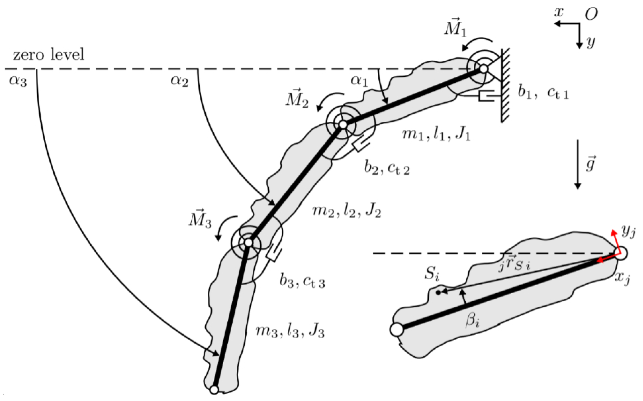
Here, a mechanical model of the robotic finger is proposed (see Figure 12), which is intended to serve as a basis for developing a control system for the finger and, subsequently, the entire hand. Equations of motion are derived. The model represents a triple physical pendulum. The grey pendulum links with a continuous black rod are rigid bodies that represent the finger links of the robotic finger. Each finger link has a mass m i , a moment of inertia J i , a length l i , and a center of gravity S i . In addition to the overall structure of each finger link, the masses m i and the moments of inertia J i take into account the pneumatic compliant actuators, which are not listed as separate elements for simplicity. Furthermore, they should be included in the coordinates of the centers of gravity S i , whose positions are generally formulated and, therefore, arbitrary. The length of the vector r S i j and the offset angle β i describe the positions of the centers of gravity. The left index stands for a coordinate system specific to each link and is positioned in the joint on which the link hangs. Its x-axis always follows a straight line along the link to the next joint, and the y-axis is perpendicular, as indicated in red in Figure 12. The link lengths l i of the pendulum extend in a straight line between the rotation points. The torques M 1 , M 2 , and M 3 represent pressure-dependent torques generated by the actuators. The angle dependency of the torques is neglected in the first approximation. The spiral symbols in Figure 12 represent torsion springs with the torsion spring stiffnesses c t i , which model the pressure-dependent torsional stiffnesses of the actuators mounted on the joints. The joint friction is taken into account by damping b i . To generalize the model, the pressure dependencies are omitted.
The Lagrangian formalism is used for the derivation of the equations of motion, which is described, e.g., by Janschek [33]. For this purpose, the Euler–Lagrange equations of the second kind are used:
d d t L ( q , q ˙ ) q i ˙ L ( q , q ˙ ) q i = f i D i , i = 1 , 2 , 3
where the Lagrangian function is given by
L ( q , q ˙ ) = T * ( q , q ˙ ) V ( q )
Here, q denotes the generalized coordinates, f i represents the generalized external forces, and D i represents the dissipative forces. First, the kinetic coenergy T * and the potential energy V need to be established, from which the Lagrangian function is composed. The mechanical model can be described using three independent minimal generalized coordinates q = ( α 1 , α 2 , α 3 ) T , as indicated in Figure 12. The rigid body motion always includes translational and rotational components, which must be taken into account when establishing the kinetic coenergy T * with respect to the center of mass. For this purpose, the position vectors r S i to the center of masses of the finger elements are first determined:
r S 1 = r S 1 1 cos ( α 1 + β 1 ) r S 1 1 sin ( α 1 + β 1 ) ,
r S 2 = l 1 cos ( α 1 ) + r S 2 2 cos ( α 2 + β 2 ) l 1 sin ( α 1 ) + r S 2 2 sin ( α 2 + β 2 ) ,
r S 3 = l 1 cos ( α 1 ) + l 2 cos ( α 2 ) + r S 3 3 cos ( α 3 + β 3 ) l 1 sin ( α 1 ) + l 2 sin ( α 2 ) + r S 3 3 sin ( α 3 + β 3 )
With the chosen minimal generalized coordinates α 1 , α 2 , and α 3 , the equations for the kinetic coenergy can be written as
T * ( q , q ˙ ) = 1 2 m 1 r ˙ S 1 2 + 1 2 m 2 r ˙ S 2 2 + 1 2 m 3 r ˙ S 3 2 + 1 2 J 1 α ˙ 1 2 + 1 2 J 2 α ˙ 2 2 + 1 2 J 3 α ˙ 3 2
and the potential energy can be written as
V ( q ) = 1 2 c t 1 ( α 1 α 10 ) 2 + 1 2 c t 2 ( α 2 α 1 α 20 ) 2 + 1 2 c t 3 ( α 3 α 2 α 30 ) 2 m 1 g r S 1 , 2 m 2 g r S 2 , 2 m 3 g r S 3 , 2
The reference level for calculating the potential energy is indicated in Figure 12. To formulate the potential energy in general terms, angles α 10 , α 20 , and α 30 are introduced to describe the rest positions of the finger elements. In this case, they are all zero, which is achieved by choosing a coordinate system. The angles of the rest positions are defined absolutely from the dashed line to the corresponding finger element. Then, the Lagrangian function L can be established by substituting Equations (6) and (7) into Equation (2). The Lagrangian function, along with the generalized applied forces f = ( M 1 , M 2 , M 3 ) T and the dissipative forces
D i = d ( q ˙ ) q i ˙
with the Rayleigh dissipation function
d ( q ˙ ) = ( 1 2 b 1 α ˙ 1 2 , 1 2 b 2 ( d d t ( α 2 α 1 ) 2 , 1 2 b 3 ( d d t ( α 3 α 2 ) 2 ) T
can now be substituted into Equation (1) to calculate the equations of motion for the motion directions α 1 , α 2 , and α 3 . Due to the computational complexity, the calculations are implemented and computed in a computer algebra system (CAS).

4.2. Angular Displacement–Pressure Characteristic of a Joint

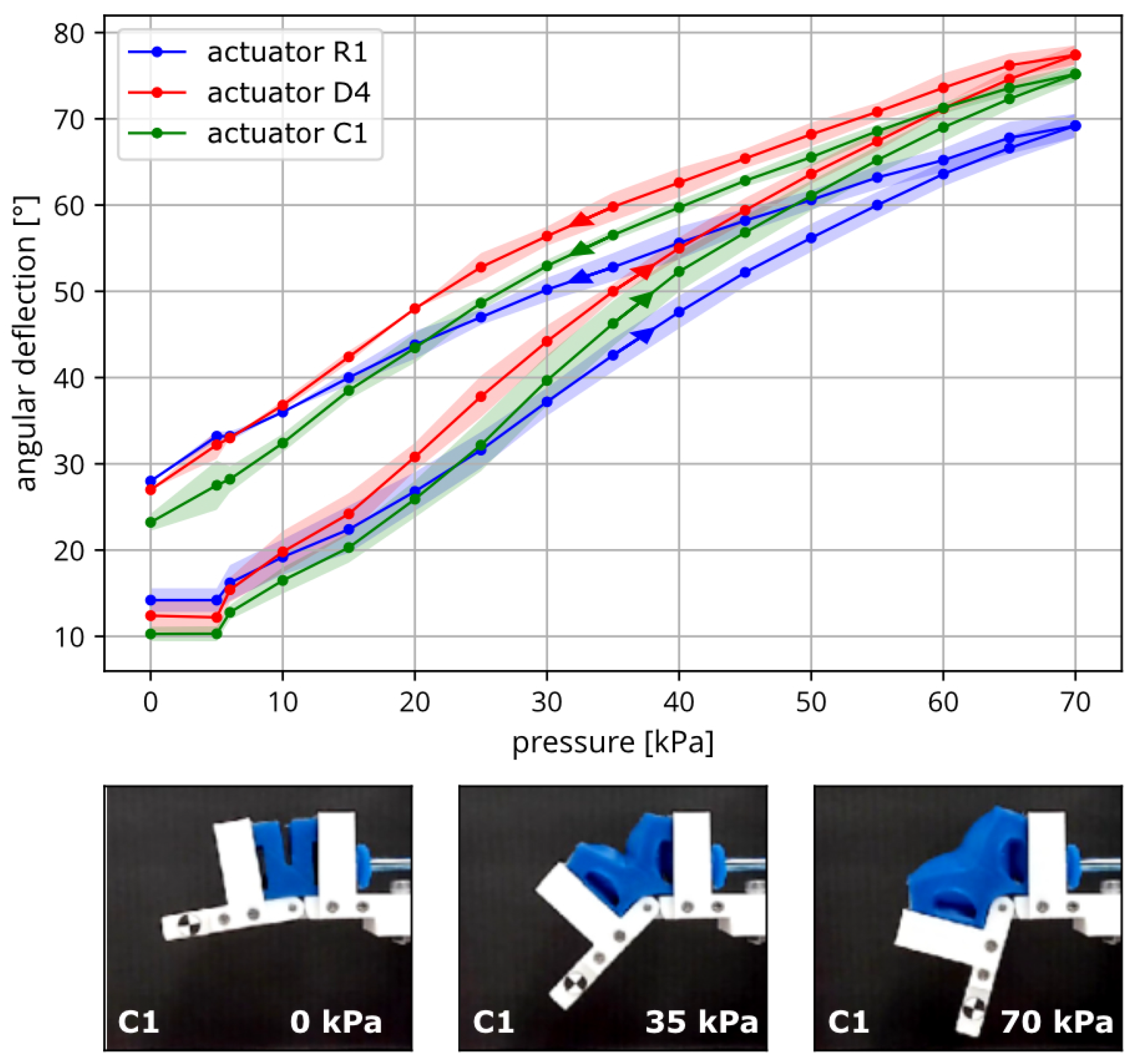
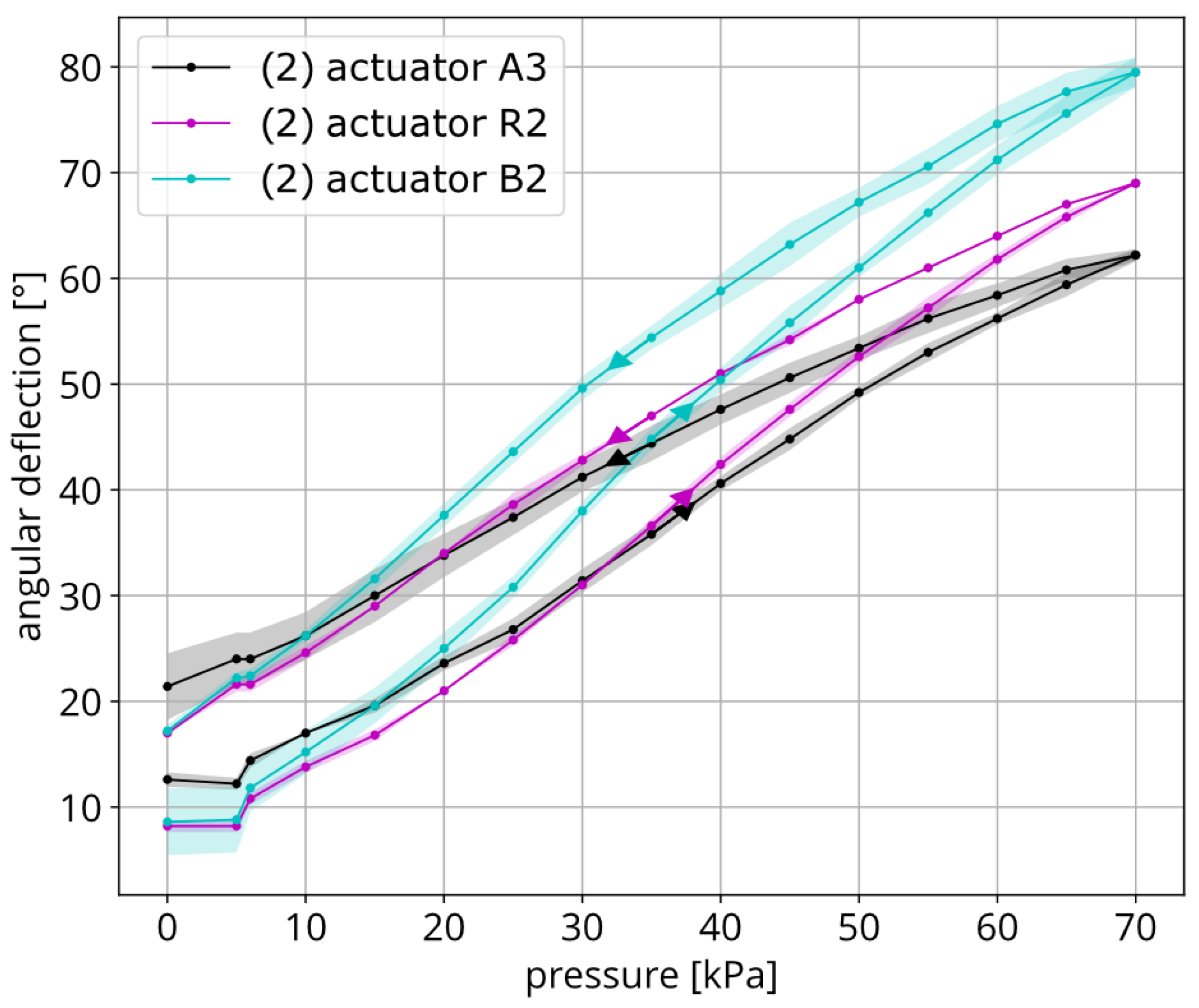
Six actuator specimens were examined for the angular deflection versus pressure response: three with one connection (R1, D4, C1) and three with two connections (A3, R2, B2). The pressure was incrementally increased in each actuator and decreased afterward, as indicated in the diagrams by an arrow pointing up and down. At first, we observe a nonlinear dependence of the angular displacement to pressure in Figure 4 and Figure 5, which can be explained by the nonlinear stress–strain behavior of Mold Star 30. Hysteresis was observed in all the actuators studied, which means that the deflection angle varied depending on the inflation and deflation. The cause was friction at the contact between the compliant pneumatic actuator and surrounding rigid parts. When pressurized with compressed air, the actuator moves out of the frame and does not return to the initial state when the pressure is released because the friction prevents it. Each actuator specimen shows a slightly different curve, especially in Figure 5, the cause of which can be attributed to repeatability in manufacturing the actuators. The maximum difference in angular displacement was 17.3° and occurred at 70 kPa. When comparing the results of the actuators with one port shown in Figure 4 and the actuators with two ports shown in Figure 5, no trends can be identified that would indicate the different behavior of these two actuator variants. Actuator B2 with two ports achieved a maximum angular displacement of 79.5° from the studied actuators. The maximum expanded uncertainty reached ±3.14°. Actuator R2 showed the lowest expanded uncertainty of ±1.12°, which shows that improvement is possible.
Hysteresis in the angular deflection–pressure characteristics of the actuator is influenced by both viscoelastic material behavior and mechanical boundary conditions, particularly friction and wall deformation. Measures should be taken to ensure that the friction conditions are implemented in a more defined and controlled manner, although achieving and accurately measuring such conditions remains challenging. The following discusses specific issues observed in the current setup, along with corresponding design recommendations for reducing the hysteresis.
First, the bulging of the actuator walls opposite the support walls may increase the deflection of the finger joint, but it also causes the actuator to shift out of the mounting frame. Due to the current tight fit and the resulting increased friction, the actuator cannot easily return to its original position. Bulging could be mitigated by making the wall stiffer or bonding it to the frame, which would reduce the hysteresis. The tight fit is partly a result of general dimensional constraints. However, it has also been observed that the actuators are approximately 1 mm wider than intended. Reducing the dimensions of the main body would help restore the intended fit.
Second, while increasing the gap between the actuator and the frame reduces friction and allows the actuator to move more freely, it also increases the risk of slippage. To address this, the fixing frame should be extended to better contain the actuator and prevent it from slipping out during operation. A potential design solution is to surround more of the actuator while still allowing a loose internal fit. This should help limit the hysteresis, but it eliminates the passive extension capability of the joint. Another idea is to fix the silicone actuator to the rigid parts using form-fit fixing points, thereby ensuring it returns to its original position.
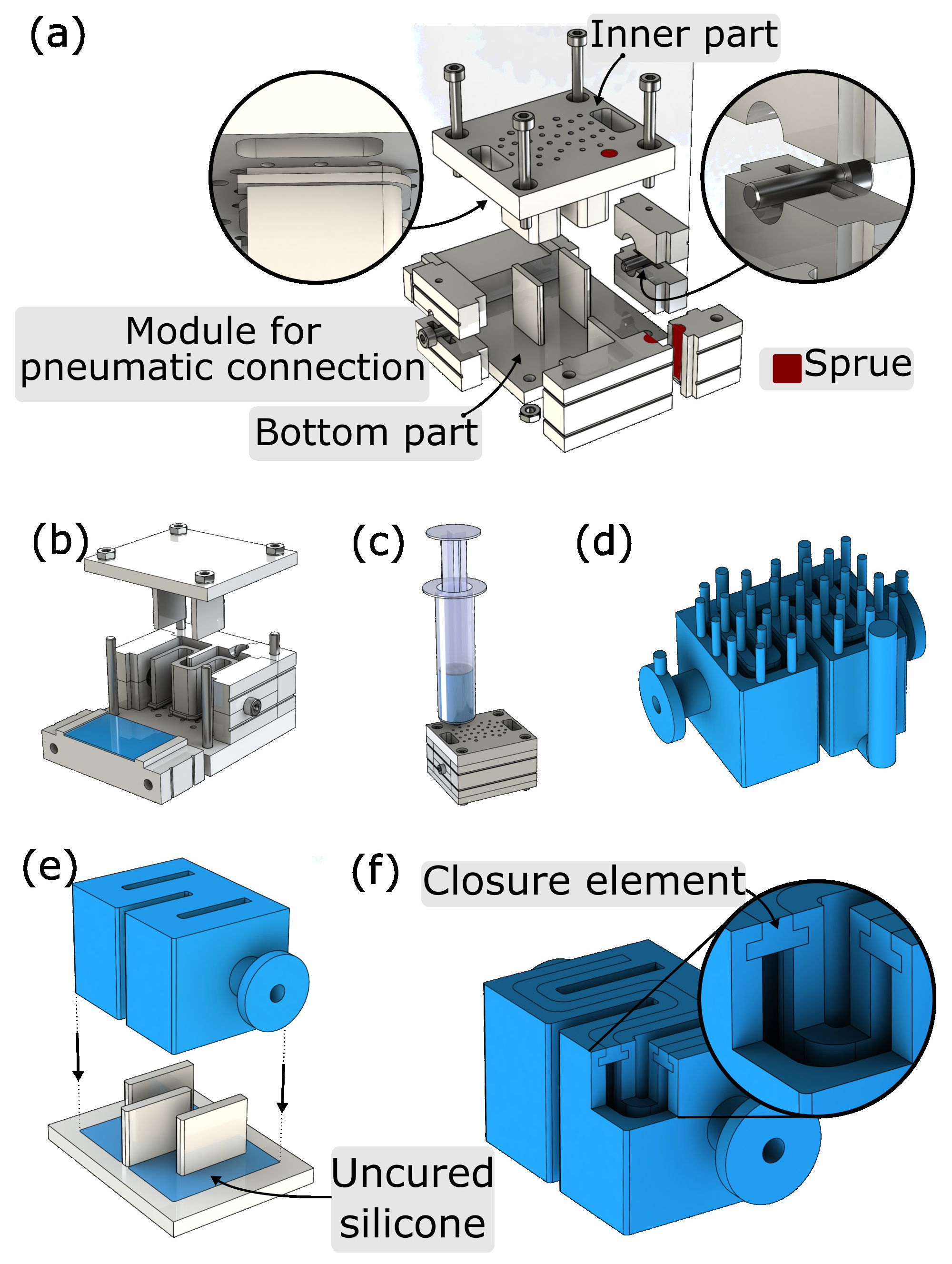
With regard to the manufacturing process, the side wall of the actuator, which is sealed in a subsequent step, should be carefully examined for its geometric consistency. The cutout used to seal the side wall may benefit from modification to allow for a uniform and consistent distribution of silicone. To facilitate this, the protruding walls could be designed to be removable, enabling even silicone distribution with the aid of a squeegee. However, achieving complete symmetry remains challenging, as the inner shape cannot be formed as precisely as the opposing side, which is created using the inner core. This issue could be addressed by adapting the manufacturing process so that both side walls are produced using the same method, thereby improving the symmetry.

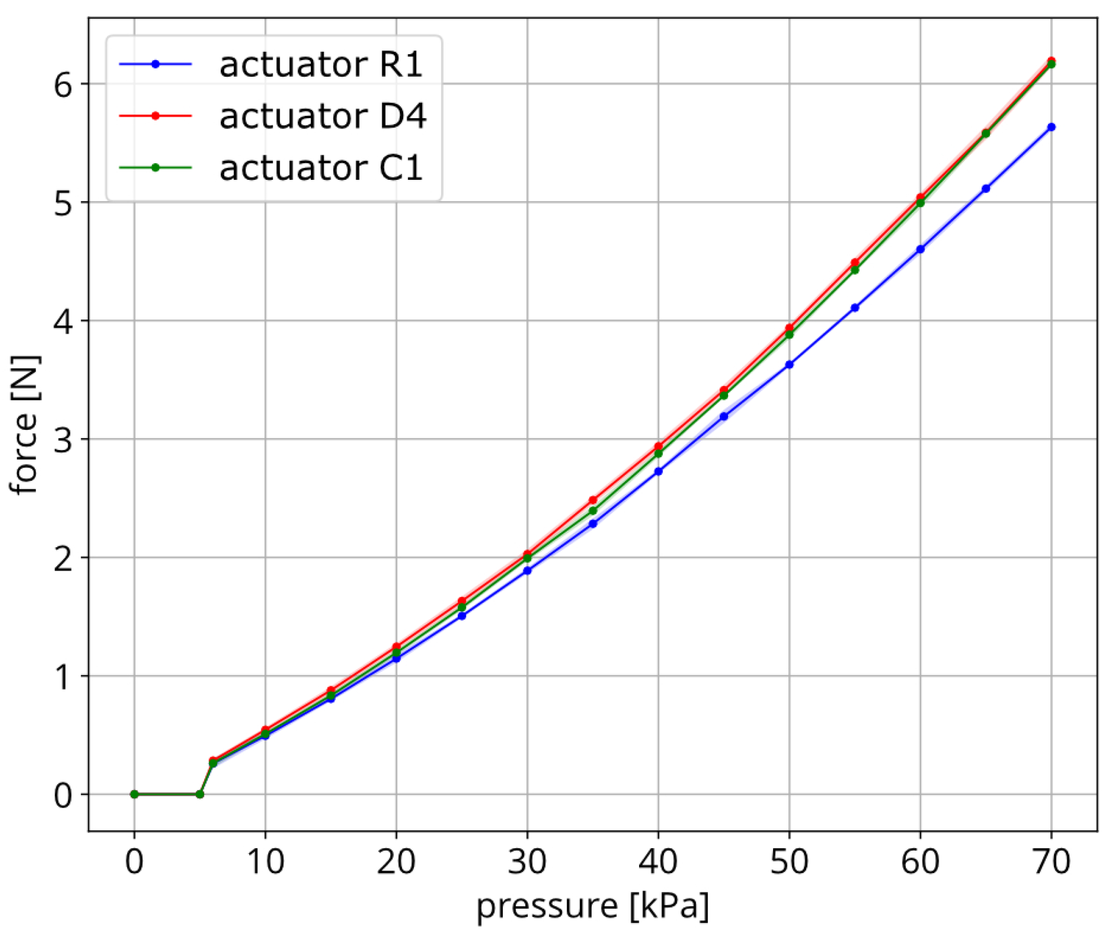
4.3. Blocking Force–Pressure Characteristic of a Joint

We studied the identical actuator specimens with one connection (R1, D4, C1), as in Section 4.2, and the recorded data are shown in Figure 6. The maximal blocking force reached by the actuator D4 was 6.19 N at 70 kPa, which was the final value of the pressure range studied. The repeatability of each sample was in the range of ±0.06 N, which corresponded to the value of maximum expanded uncertainty and included 97.5% of the values. One of the actuators performed visibly worse than the remaining two and reached a blocking force of 5.63 N.
In conclusion, the results demonstrate a consistent increase in the blocking force with applied pressure, with good repeatability among the actuator samples. The performance of two out of three actuators indicates reliable functionality, while the lower output of one sample suggests the need for tighter quality control or further investigation into variability. Since the maximum pressure tested was 70 kPa and the force output had not plateaued, further testing at higher pressures could help determine whether a saturation point exists for this actuator design.

4.4. Fingertip Force Benchmarking

The measured blocking force of a single joint was used to estimate the total fingertip force of the finger. Based on the joint geometry, this corresponded to a torque of M = F · a = 6.19 N · 0.035 m = 0.2 Nm . Assuming equal torques across all three joints and known distances from each joint to the fingertip ( a 1 = 0.142 m, a 2 = 0.086 m, a 3 = 0.04 m), the fingertip force was calculated by summing the torques divided by their respective lever arms: F = M 1 / a 1 + M 2 / a 2 + M 3 / a 3 = 0.2 / 0.142 + 0.2 / 0.086 + 0.2 / 0.04 1.4 + 2.3 + 5 = 8.7 N . This estimated value at 70 kPa is used in Table 1 to benchmark the fingertip force performance of the proposed system against related work.
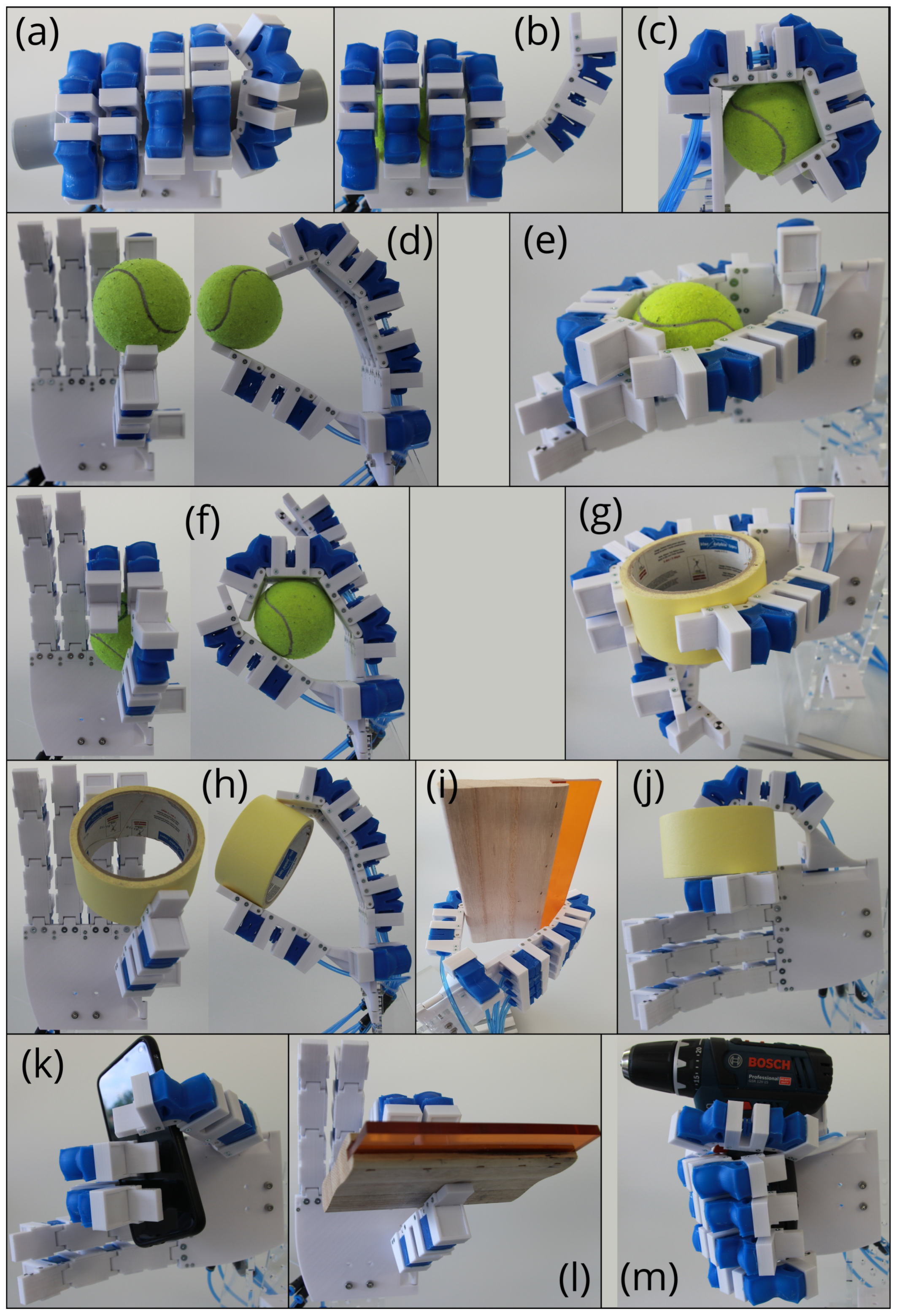
4.5. Grasp Variety

The hand’s gripping ability was tested upright and horizontally with six different objects of different shapes, sizes, and weights. The results are documented in Figure 13. Objects were given to the hand and its fingers were operated by manually adjusting the pressure to reach the desired position, as shown in Figure 11. The robotic gripper performed a two-finger precision grip (Figure 13d), a three-finger precision grip (Figure 13h,l), a side grip (Figure 13j), and a strong grip (Figure 13a–c,m). Figure 13f,g,i,k show how joints controlled with the same channel perform a different flexion upon contact with an object, which is due to the inherent softness of soft pneumatic actuators. In some cases, however, it would be advantageous to control some joints separately or to place soft pads on the palm and finger surfaces. In Figure 13h, for example, it can be observed how the index finger lost contact with the object as the pressure increased further and more force was introduced via the edge of the finger. In this case, it was advantageous to drive the PIP and/or MCP joints instead of the DIP joint so that the finger end link made sufficient contact. Especially in this control configuration, precise gripping of small objects was only possible with the edge of the finger end link, as shown in Figure 13d. In this case, it was necessary to mount the soft fingertips to increase the contact area.

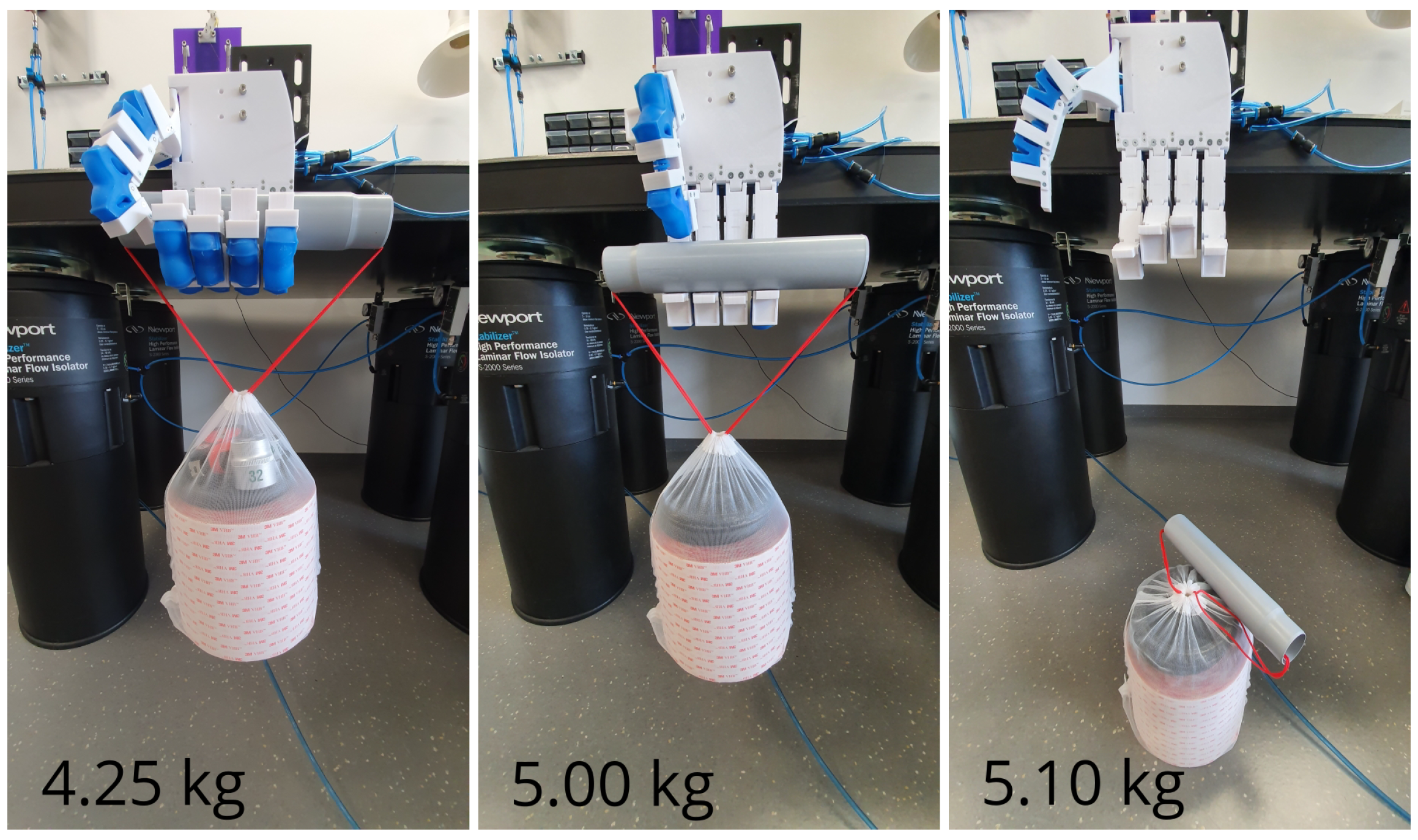
4.6. Weighted Suitcase Grip Test

This section describes a test in which the hand was directed vertically downward to perform a suitcase grip test. A pressure of 80 kPa was applied to the hand. The weights were placed in a bag with a cylindrical handle of relatively large diameter (45 mm) to prevent the bag’s line from becoming wedged in the hand. The hand could stably hold 4.25 kg, as shown in Figure 14.

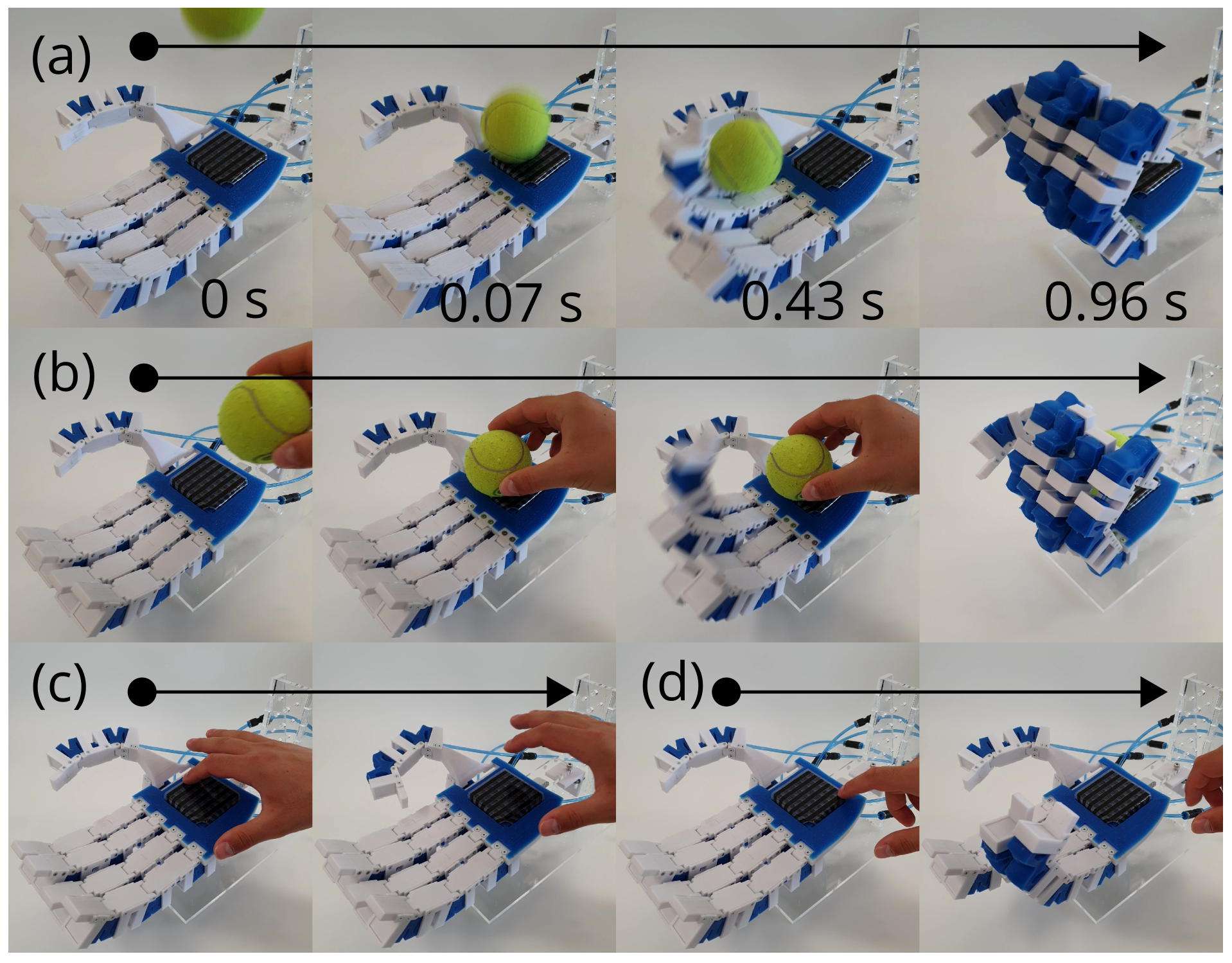
4.7. Demonstrations of Hand Features That Incorporated Tactile Sensor Array

Three demonstrations were programmed and performed. All are shown in Figure 15, in which the hand (I) detects and catches a falling object, (II) detects the object somewhere on the palm and grasps it, (III) actuates different fingers depending on the row of sensors pressed, thus proving the operation of the sensor array.
Currently, such a sensor array could support vision systems with tactile feedback, e.g., when approaching an object by palpation, but also by giving the hand automatic functions to close the grip. Future enhancements to the tactile sensor array, from a position sensor to small distributed pressure sensors, combined with their integration into the fingers, will enable new functions, such as shape recognition, grip adjustment, weight sensing, and preventing the hand from exerting high forces and crushing objects.

5. Toolkit

The presented robotic hand can serve as a demonstration and test platform for resistive tactile and other sensors and sensor arrays. The CAD models of the joints are provided in the Supplementary Materials. The joint is conceptually and constructively the most exciting part of the hand, which is repeated in the anthropomorphic gripper. To emphasize again: the plastic skeletal structures and the pneumatic soft bending actuator are considered as a joint together. CAD models of the plastic skeletal parts, the pneumatic bending actuator, and the molds are shared to enable others to use, modify, and eventually develop their robotic structures based on the joint design to accelerate progress.

6. Discussion

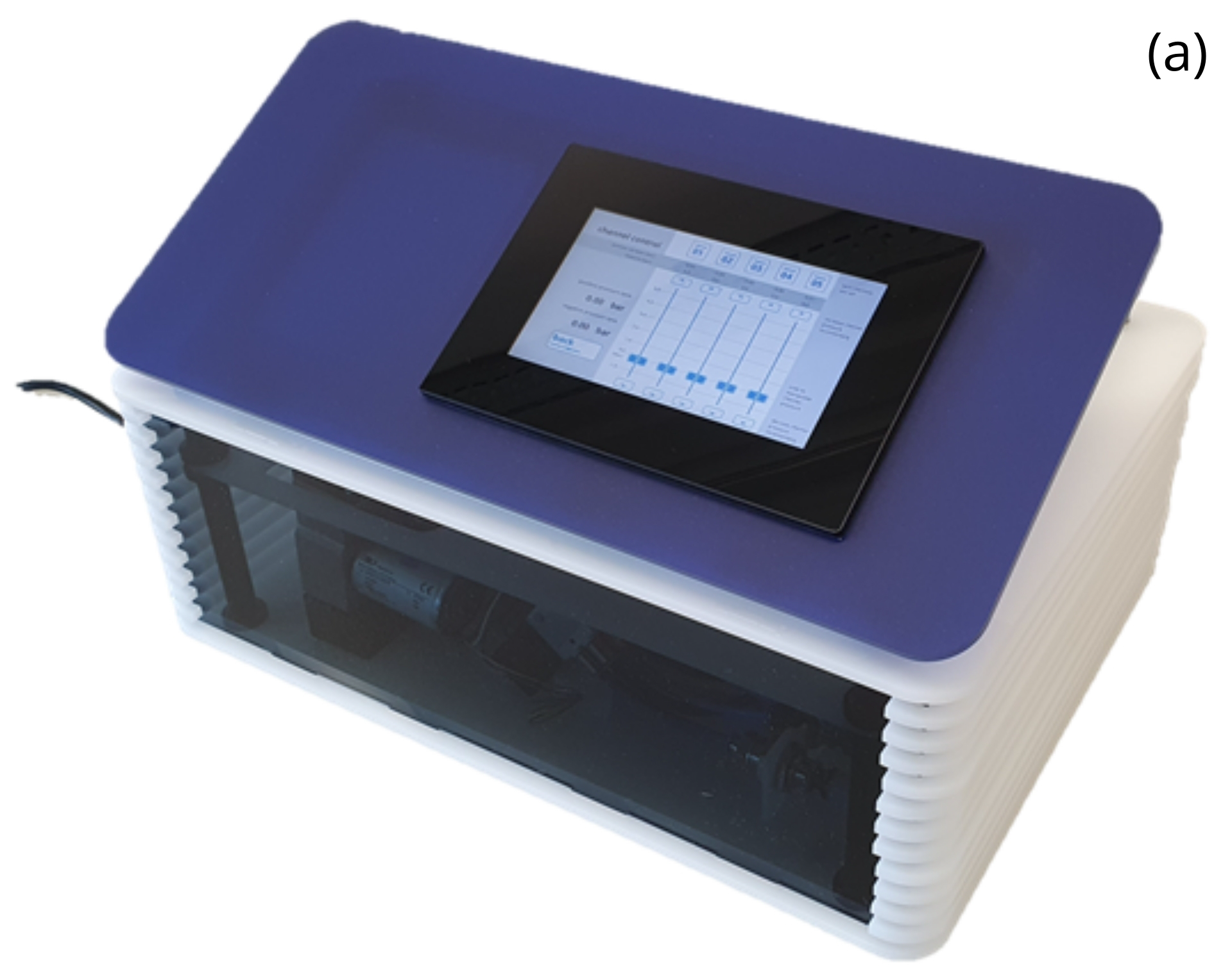
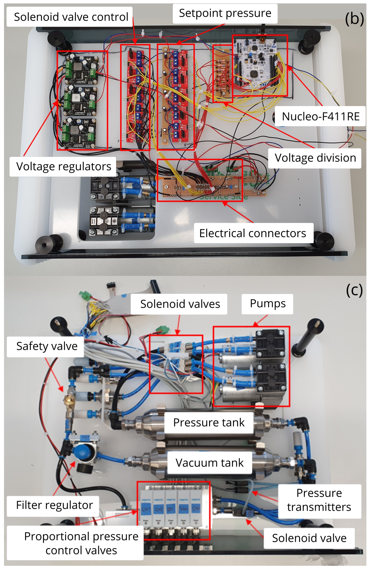
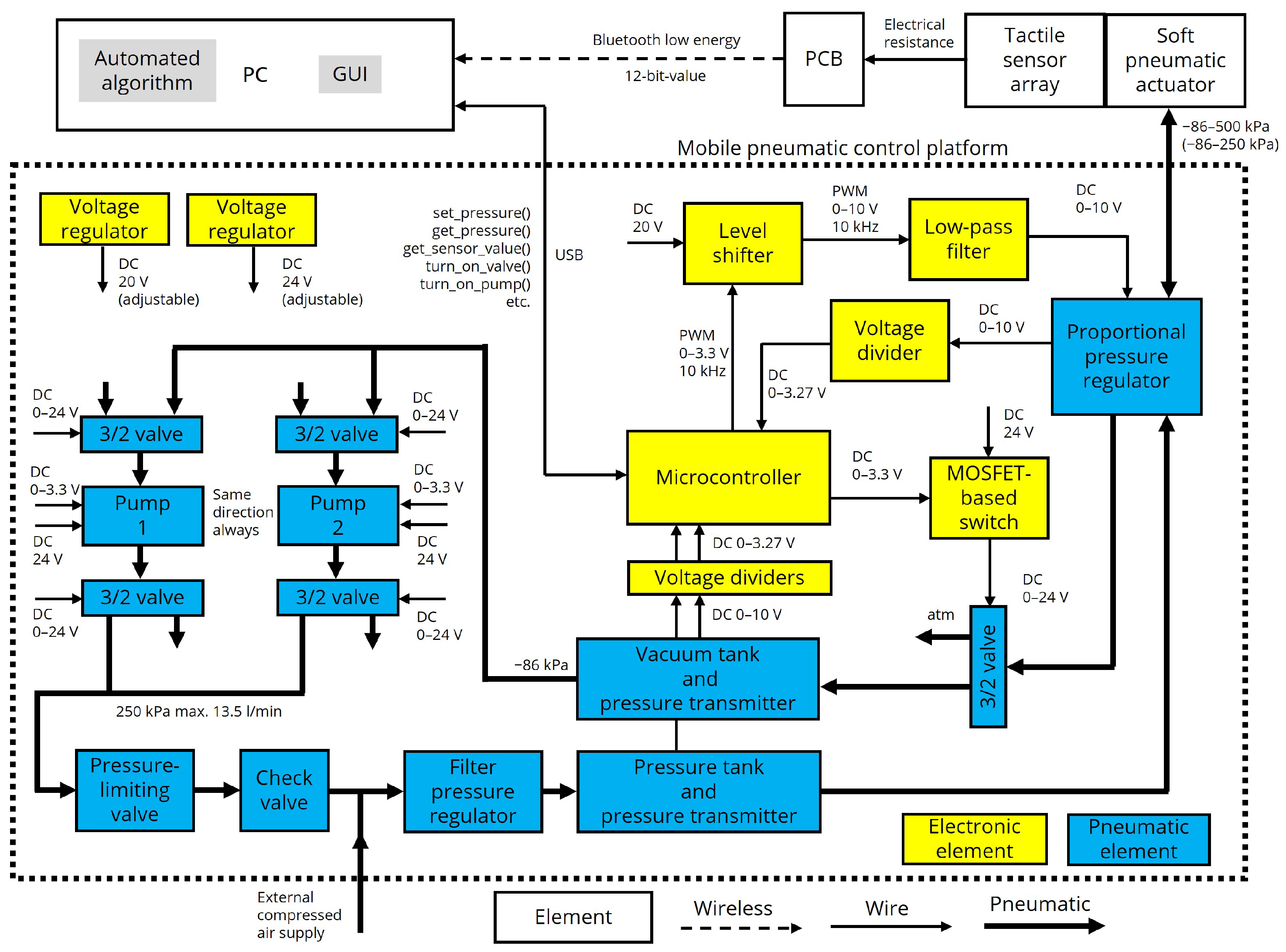
This work presents a low-cost prototype of a soft–rigid hybrid anthropomorphic robotic gripper, which can be completely built using FDM and molding methods. This is an alternative to robotic hands available on the market, which are generally very expensive and unaffordable for every researcher or startup. The five-fingered gripper is directly driven by 15 soft pneumatic bending actuators placed on each joint but controlled by five pressure-controlled lines. The compressibility of the pneumatic bending actuators enables each joint to achieve different bending angles, depending on the objects being gripped or the environmental constraints, even when pressurized by the same control line. Thus, the actuators do not have to be controlled separately, significantly simplifying the control. In contrast to conventional robotics, we pursued a combination of soft and rigid parts to maintain adaptability but keep the structure more mechanically stable by using rigid parts. The skeleton structure defines the otherwise infinite degrees of freedom of soft pneumatic actuators and focuses the motion they generate. As it is intended to be a testing platform for tactile sensor arrays, our robotic hand is characterized by large rigid surface areas on the phalanges for placing sensors, which could be achieved using hinge joints. The rigidity of the phalanges prevents the unintended activation of the tactile sensor arrays, which could be caused by the environment or by the pneumatic bending actuators. In this work, only a resistive tactile sensor was integrated into the palm of the hand. Joints with discrete rotation points simplify the kinematics of pneumatic soft bending actuators to forward kinematics. For the development of future control, we propose a mechanical model that first describes the behavior of one robotic finger and provides the equations of motions. The parameters of the mechanical model, e.g., spring stiffness, damping, or torques, have not yet been calculated or estimated experimentally and have to be determined. The robotic hand and a single joint were experimentally investigated. As a result, the gripper could grasp objects of different shapes and sizes, even though it was controlled with five air channels, but the integration of finger pads would improve the performance. From a strength standpoint, the hand held 4.5 kg in the weighted suitcase test, where the hand hung with the fingers pointing down. At the maximum test pressure of 70 kPa, a single joint achieved a maximum blocking force of 6.19 N and a maximum angular displacement of 79.5°, which was different from the desired 90°. However, the pressure could be further increased to reach the desired maximal angular deflection. When we examined a single joint, we found poor reproducibility regarding angular displacement, which we attribute to the second general manufacturing step of the pneumatic soft bending actuators. In this step, the actuator was dipped in silicone to close the remaining sidewall, the shape and dimensions of which could not be controlled well. We tended to have better reproducibility in terms of the blocking force. With an integrated resistive sensor array on the palm of the hand, we demonstrated reflexive features and position sensing. We demonstrated that the hand could grasp falling objects or perceive and grasp objects it touched with the help of the tactile sensor. In order to fully exploit the potential of the sense of touch, sensors must also be integrated into the fingers, and further investigations must be carried out. We have also presented our mobile pneumatic control platform with detailed information about its pneumatic and electric circuits. Finally, we provide CAD files for manufacturing a single soft–rigid hybrid pneumatic joint, which can serve as a building block and accelerate the design of robotic structures.

Supplementary Materials

The following supporting information can be downloaded from https://www.mdpi.com/article/10.3390/act14050252/s1. Supplementary Video S1; CAD Files S2: STEP files of the pneumatic soft bending actuator; CAD Files S3: Joint STEP files; CAD Files S4: STEP files of mold parts.

Author Contributions

Conceptualization, R.A., M.S. and E.-F.M.V.; methodology, R.A. and M.S.; software, R.A.; validation, R.A. and M.S.; formal analysis, R.A. and M.S.; investigation, R.A.; resources, E.-F.M.V. and J.N.; data curation, R.A.; writing—original draft preparation, R.A.; writing—review and editing, E.-F.M.V., M.S. and A.R.; visualization, R.A.; supervision, E.-F.M.V. and M.S.; project administration, E.-F.M.V. and A.R.; funding acquisition, E.-F.M.V. and A.R. All authors have read and agreed to the published version of this manuscript.

Funding

This research was funded by the Deutsche Forschungsgemeinschaft (DFG, German Research Foundation)—418669083 and by the Federal Ministry of Education and Research of Germany in the program of “Souverän. Digital. Vernetzt.”. Joint project 6G-life, project identification number: 16KISK001K.

Data Availability Statement

The raw data supporting the conclusions of this article will be made available by the authors upon request.

Conflicts of Interest

Authors Moritz Scharff, Junhao Ni and E.-F. Markus Vorrath were employed by the company PowerON Group. The remaining authors declare that the research was conducted in the absence of any commercial or financial relationships that could be construed as a potential conflict of interest.

References

  1. Nathalia Gama Melo, E.; Fernando Avilés Sánchez, O.; Amaya Hurtado, D. Anthropomorphic robotic hands: A review Manos robóticas antropomórficas: Una revisión. Ing. Y Desarro. 2014, 32, 279–313. [Google Scholar] [CrossRef]
  2. Shintake, J.; Cacucciolo, V.; Floreano, D.; Shea, H. Soft Robotic Grippers. Adv. Mater. 2018, 30, 1707035. [Google Scholar] [CrossRef] [PubMed]
  3. Piazza, C.; Grioli, G.; Catalano, M.G.; Bicchi, A. A Century of Robotic Hands. Robot. Auton. Syst. Annu. Rev. Control Robot. Auton. Syst. 2019, 22, 1–32. [Google Scholar] [CrossRef]
  4. Chalon, M.; Maier, M.; Bertleff, W.; Beyer, A.; Bayer, R.; Friedl, W.; Neugebauer, P.; Obermeier, T.; Sedlmayr, H.J.; Seitz, N.; et al. Spacehand: A Multi-Fingered Robotic Hand for Space. In Proceedings of the Symposium on Advanced Space Technologies in Robotics and Automation, Noordwijk, The Netherlands, 11–13 May 2015; European Space Agency: Pairs, France, 2015; pp. 1–8. [Google Scholar]
  5. Shadow Robot Company. Shadow Dexterous Hand Series—Research and Development Tool. 2023. Available online: https://www.shadowrobot.com/dexterous--hand--series/ (accessed on 5 May 2023).
  6. SCHUNK SE & Co. KG. SVH 5-Finger Servo-Electric Gripping Hand. 2023. Available online: https://www.schunk.com/de/en/gripping–systems/special–gripper/svh/c/PGR_3161 (accessed on 5 May 2023).
  7. Xu, Z.; Todorov, E. Design of a highly biomimetic anthropomorphic robotic hand towards artificial limb regeneration. In Proceedings of the IEEE International Conference on Robotics and Automation, Stockholm, Sweden, 16–21 May 2016; pp. 3485–3492. [Google Scholar] [CrossRef]
  8. Santina, C.D.; Piazza, C.; Grioli, G.; Catalano, M.G.; Bicchi, A. Toward Dexterous Manipulation with Augmented Adaptive Synergies: The Pisa/IIT SoftHand 2. IEEE Trans. Robot. 2018, 34, 1141–1156. [Google Scholar] [CrossRef]
  9. Deimel, R.; Brock, O. A novel type of compliant and underactuated robotic hand for dexterous grasping. Int. J. Robot. Res. 2015, 35, 161–185. [Google Scholar] [CrossRef]
  10. Nemoto, Y.; Ogawa, K.; Yoshikawa, M. F3Hand: A Five-Fingered Prosthetic Hand Driven with Curved Pneumatic Artificial Muscles. In Proceedings of the 2018 40th Annual International Conference of the IEEE Engineering in Medicine and Biology Society (EMBC), Honolulu, HI, USA, 18–21 July 2018; IEEE: New York, NY, USA, 2018; pp. 1668–1671. [Google Scholar] [CrossRef]
  11. Fras, J.; Althoefer, K. Soft Biomimetic Prosthetic Hand: Design, Manufacturing and Preliminary Examination. In Proceedings of the IEEE International Conference on Intelligent Robots and Systems, Madrid, Spain, 1–5 October 2018; IEEE: New York, NY, USA, 2018; pp. 6998–7003. [Google Scholar] [CrossRef]
  12. Chen, Y.; Le, S.; Tan, Q.C.; Lau, O.; Song, C. A Lobster-Inspired Hybrid Actuator with Rigid and Soft Components. In The American Society of Mechanical Engineers, Proceedings of the International Design Engineering Technical Conferences and Computers and Information in Engineering Conference, Cleveland, OH, USA, 6–9 August 2017; ASME: New York, NY, USA, 2017; Volume 5B. [Google Scholar] [CrossRef]
  13. Galloway, K.C.; Polygerinos, P.; Walsh, C.J.; Wood, R.J. Mechanically programmable bend radius for fiber-reinforced soft actuators. In Proceedings of the 2013 16th International Conference on Advanced Robotics (ICAR), Montevideo, Uruguay, 25–29 November 2013; IEEE: New York, NY, USA, 2013; pp. 1–6. [Google Scholar] [CrossRef]
  14. Gafer, A.; Heymans, D.; Prattichizzo, D.; Salvietti, G. The Quad-Spatula Gripper: A Novel Soft-Rigid Gripper for Food Handling. In Proceedings of the 2020 3rd IEEE International Conference on Soft Robotics (RoboSoft), New Haven, CT, USA, 15 May–15 July 2020; pp. 39–45. [Google Scholar] [CrossRef]
  15. Zhu, W.; Lu, C.; Zheng, Q.; Fang, Z.; Che, H.; Tang, K.; Zhu, M.; Liu, S.; Wang, Z. A Soft-Rigid Hybrid Gripper With Lateral Compliance and Dexterous In-Hand Manipulation. IEEE/ASME Trans. Mechatronics 2023, 28, 104–115. [Google Scholar] [CrossRef]
  16. Godaba, H.; Sajad, A.; Patel, N.; Althoefer, K.; Zhang, K. A two-fingered robot gripper with variable stiffness flexure hinges based on shape morphing. In Proceedings of the 2020 IEEE International Conference on Intelligent Robots and Systems (IROS), Las Vegas, NV, USA, 24 October 2020–24 January 2021; pp. 8716–8721. [Google Scholar] [CrossRef]
  17. Mohd Faudzi, A.A.; Ooga, J.; Goto, T.; Takeichi, M.; Suzumori, K. Index Finger of a Human-Like Robotic Hand Using Thin Soft Muscles. IEEE Robot. Autom. Lett. 2018, 3, 92–99. [Google Scholar] [CrossRef]
  18. Deshpande, A.D.; Xu, Z.; Weghe, M.J.V.; Brown, B.H.; Ko, J.; Chang, L.Y.; Wilkinson, D.D.; Bidic, S.M.; Matsuoka, Y. Mechanisms of the Anatomically Correct Testbed Hand. IEEE/ASME Trans. Mechatronics 2013, 18, 238–250. [Google Scholar] [CrossRef]
  19. Zhang, N.; Zhou, P.; Yang, X.; Shen, F.; Ren, J.; Hou, T.; Dong, L.; Bian, R.; Wang, D.; Gu, G.; et al. Biomimetic rigid-soft finger design for highly dexterous and adaptive robotic hands. Sci. Adv. 2025, 11, eadu2018. [Google Scholar] [CrossRef] [PubMed]
  20. Li, H.; Ford, C.J.; Lu, C.; Lin, Y.; Bianchi, M.; Catalano, M.G.; Psomopoulou, E.; Lepora, N.F. Tactile SoftHand-A: 3D-Printed, Tactile, Highly-underactuated, Anthropomorphic Robot Hand with an Antagonistic Tendon Mechanism. arXiv 2024, arXiv:2406.12731. [Google Scholar] [CrossRef]
  21. Zhang, N.; Ge, L.; Xu, H.; Zhu, X.; Gu, G. 3D printed, modularized rigid-flexible integrated soft finger actuators for anthropomorphic hands. Sens. Actuators A Phys. 2020, 312, 112090. [Google Scholar] [CrossRef]
  22. Xu, Z.; Bai, Y.; Ni, R.; Yang, N.; Sun, Y.; Qi, P. Anthropomorphic Soft Pneumatic Fingers Towards Full Dexterity of Human Hand. In Proceedings of the 2018 IEEE-RAS 18th International Conference on Humanoid Robots (Humanoids), Beijing, China, 6–9 November 2018; pp. 381–386. [Google Scholar] [CrossRef]
  23. DexHand. DexHand—An Open Source Dexterous Humanoid Robot Hand. 2025. Available online: https://www.dexhand.org/ (accessed on 10 May 2025).
  24. Christoph, C.C.; Eberlein, M.; Katsimalis, F.; Roberti, A.; Sympetheros, A.; Vogt, M.R.; Liconti, D.; Yang, C.; Cangan, B.G.; Hinchet, R.J.; et al. ORCA: An Open-Source, Reliable, Cost-Effective, Anthropomorphic Robotic Hand for Uninterrupted Dexterous Task Learning. arXiv 2025, arXiv:2504.04259. [Google Scholar] [CrossRef]
  25. Shaw, K.; Agarwal, A.; Pathak, D. LEAP Hand: Low-Cost, Efficient, and Anthropomorphic Hand for Robot Learning. arXiv 2023, arXiv:2309.06440. [Google Scholar] [CrossRef]
  26. Lotfiani, A.; Yi, X.; Qinzhi, Z.; Shao, Z.; Wang, L. Design and Experiment of a Fast-Soft Pneumatic Actuator with High Output Force. In Intelligent Robotics and Applications, Proceedings of the International Conference on Intelligent Robotics and Applications (ICIRA 2018), Newcastle, NSW, Australia, 9–11 August 2018; Springer International Publishing: Cham, Switzerland, 2018; Volume 10984 LNAI, pp. 442–452. [Google Scholar] [CrossRef]
  27. Connolly, F.; Polygerinos, P.; Walsh, C.J.; Bertoldi, K. Mechanical Programming of Soft Actuators by Varying Fiber Angle. Soft Robot. 2015, 2, 26–32. [Google Scholar] [CrossRef]
  28. Sommer, K.D.; Siebert, B.R. Praxisgerechtes bestimmen der messunsicherheit nach GUM. Tech. Mess. 2004, 71, 52–66. [Google Scholar] [CrossRef]
  29. Grebenstein, M.; Chalon, M.; Hirzinger, G.; Siegwart, R. A Method for Hand Kinematics Designers 7 Billion Perfect Hands. In Proceedings of the 1st International Conference on Applied Bionics and Biomechanics ICABB-2010, Venice, Italy, 14–16 October 2010. [Google Scholar]
  30. Feix, T.; Romero, J.; Schmiedmayer, H.B.; Dollar, A.M.; Kragic, D. The GRASP Taxonomy of Human Grasp Types. IEEE Trans. Hum. Mach. Syst. 2016, 46, 66–77. [Google Scholar] [CrossRef]
  31. Anderson, I.A.; Henke, M. FLEXIBLE SWITCHES AFFECTED BY LATERAL OR VERTICAL ACTUATION. U.S. Patent US11551881B2, 10 February 2023. Available online: https://patentimages.storage.googleapis.com/c4/46/84/765eba13d0bebb/US11551881.pdf (accessed on 10 May 2025).
  32. Holland, D.; Park, E.J.; Polygerinos, P.; Bennett, G.J.; Walsh, C.J. The Soft Robotics Toolkit: Shared Resources for Research and Design. Soft Robot. 2014, 1, 224–230. [Google Scholar] [CrossRef]
  33. Janschek, K. Systementwurf Mechatronischer Systeme; Springer: Berlin/Heidelberg, Germany, 2010. [Google Scholar] [CrossRef]
  34. Kim, U.; Jung, D.; Jeong, H.; Park, J.; Jung, H.M.; Cheong, J.; Choi, H.R.; Do, H.; Park, C. Integrated linkage-driven dexterous anthropomorphic robotic hand. Nat. Commun. 2021, 12, 7177. [Google Scholar] [CrossRef] [PubMed]
  35. Liu, X.; Zhao, Y.; Geng, D.; Chen, S.; Tan, X.; Cao, C. Soft Humanoid Hands with Large Grasping Force Enabled by Flexible Hybrid Pneumatic Actuators. Soft Robot. 2021, 8, 175–185. [Google Scholar] [CrossRef] [PubMed]
Figure 1. Concept of the anthropomorphic soft–rigid hybrid gripper. Pictured actuators (light blue) serve an illustrative purpose and do not specify the particular actuator type.
Actuators 14 00252 g001
Figure 2. Finger design of (a) the pneumatic soft bending actuator with dimensions in mm. The wall thickness and inner channel widths are 2 mm. Joint design: (b) exploded view of the joint between the finger distal phalanx and the finger middle phalanx, (c) the longitudinal cross-section of the near-joint environment, (d) the maximum flexion of the joints, and (e) the finger construction without the hose connection. Distal phalanx 40 mm, middle phalanx 46 mm, and proximal phalanx 56 mm.
Actuators 14 00252 g002
Figure 3. (a) The exploded view of the main mold for the production of actuators with pneumatic connections. The manufacturing process is shown in (bf), with (b) the pre-assembled main casting mold with a thin layer of an uncured silicone for bonding the bandage, (c) the fully assembled main casting mold with a filled syringe inserted into the sprue, (d) the unmachined casting from the main casting mold, (e) the reworked cast part from the main mold dipped into the uncured silicone to cast the missing side wall on it, and (f) the finished actuator with a cuboid cutout. In the detailed view, the shape of the generated side wall (“closure element”) is illustrated by showing the edges.
Actuators 14 00252 g003
Figure 4. The angular deflection–pressure characteristics of three actuators with one connection (R1, D4, C1). Colored areas indicate the expanded measurement uncertainty.
Actuators 14 00252 g004
Figure 5. The angular deflection–pressure characteristics of three actuators with two connections (A3, R2, B2). Colored areas indicate the expanded measurement uncertainty.
Actuators 14 00252 g005
Figure 6. The force–pressure characteristics of three actuators with one connection (R1, D4, C1). The colored areas indicate the expanded measurement uncertainty (small, thus hardly visible).
Actuators 14 00252 g006
Figure 7. In (a,b), the setup for measuring the angular deflection as a function of pressure is shown, with the (a) main components of the setup and (b) insights into the video editing in Tracker software (Tracker version 5.1.5). The setup for measuring the force of the joint as a function of pressure is shown in (c,d), with (c) an overview showing the main components of the setup and (d) the detailed view of the force sensor tip and the end phalanx.
Actuators 14 00252 g007
Figure 8. Construction of the hand: (a) the mechanical representation of the robotic hand with the assignment of the control channels (colored), (b) the overall dimensions of the developed robotic hand, (c) the span between the thumb and the remaining fingers, (d) the dimensioning of the palm based on the reach of the fingers, (e) the maximum flexion of the finger and the dimensions of the enclosed area, (f) the three-finger precision grip with the side and front view, and (g) the dimensioning of the thumb.
Actuators 14 00252 g008
Figure 9. The anthropomorphic hand with the resistive tactile sensor array: (a) front side of the hand with the mounted resistive tactile sensor array; (b) back view of the hand with mounted battery-powered electronics for reading signals from a resistive array, including Bluetooth low-energy communication; and (c) a resistive tactile sensor array.
Actuators 14 00252 g009
Figure 10. Mobile pneumatic control platform: (a) the fully assembled mobile pneumatic control platform, (b) top view of the electrical circuit with the main components described, and (c) top view of the pneumatic circuit with the main components described.
Actuators 14 00252 g010aActuators 14 00252 g010b
Figure 11. The current control schematics of the system. Some elements are omitted for clarity, e.g., air filters, the main supply line, and four additional pressure regulators.
Actuators 14 00252 g011
Figure 12. Mechanical model of the developed pneumatic finger. The coordinate origin depicted is displaced from its actual location, which is at the fixed support, for the sake of clarity.
Actuators 14 00252 g012
Figure 13. Testing the grip positions with different objects: (a) strong grip on cylindrical pipe; (b) strong grip on tennis ball; (c) strong grip on tennis ball (side view); (d) two-finger precision grip on tennis ball; (e) three-finger precision grip on tennis ball (horizontally); (f) three-finger precision grip on tennis ball; (g) three-finger precision grip on adhesive tape roll (horizontally); (h) three-finger precision grip on adhesive tape roll; (i) strong grip on squeegee; (j) side grip on adhesive tape roll; (k) strong grip on smartphone; (l) three-finger grip on squeegee; (m) strong grip on electric drill. Gripped objects: pipe (diameter 45 mm, 85 g), tennis ball (diameter 80 mm, 57 g), adhesive tape (diameter 92 mm, 90 g), squeegee ((240 × 110 × 20) mm, 170 g), electric drill (970 g), and smartphone ((150 × 85 × 10) mm, 177 g).
Actuators 14 00252 g013
Figure 14. Weighted suitcase grip test of the robotic hand.
Actuators 14 00252 g014
Figure 15. Demonstration of the hand with a piezoresistive tactile sensor array: (a) sensing a tennis ball and catching it, as demonstrated in Supplementary Video S1 (see Supplementary Materials), (b) sensing a tennis ball on the palm of the hand and grabbing it, (c) a row of sensors closest to the thumb activating the distal joint of the thumb, and (d) a row of sensors furthest from the thumb activating the small and ring finger.
Actuators 14 00252 g015
Table 1. Comparison of fingertip force for different robotic hand systems.
ActuationFingertip Force
This paperPneumatic direct drive8.7 N at 80 kPa (estimated)
[34]Electric motors, linkage driven28 N
[21]Pneumatic direct drive0.84 N at 16 kPa
[35]Pneumatic direct drive15 N at 300 kPa 3.5 N at 70 kPa
[19]Electric motors, tendon-driven2 N
[4]Electric motors, gear transmission30 N
[12]Pneumatic direct drive2 N at 120 kPa
[13]Pneumatic direct drive1 N at 100 kPa
Disclaimer/Publisher’s Note: The statements, opinions and data contained in all publications are solely those of the individual author(s) and contributor(s) and not of MDPI and/or the editor(s). MDPI and/or the editor(s) disclaim responsibility for any injury to people or property resulting from any ideas, methods, instructions or products referred to in the content.

