1. Introduction
Micro-graspers play a critical role in performing delicate tasks that require high precision. They specialize in the manipulation of micro-objects, a process that revolves around three primary actions: singulation, orientation, and presentation. Practical instances of these functions include tasks such as object pick-n-place for microassembly and surgical procedures, as well as activities like pushing, throwing, and dropping [
1,
2,
3].
These graspers predominantly operate based on either a rigid motion or deforming structures. Their power source might be an innate internal force like electro-thermal expansion, or external forces like an electrostatic actuator. At present, a noticeable gap exists in small-scale gripper technologies, which mainly operate in two dimensions. To adeptly manipulate objects of irregular shapes, a three-dimensional gripper is essential [
4,
5,
6].
There are numerous techniques for producing mesoscale-compliant mechanisms at a large scale. These include methods like lithography, injection molding [
7], general molding [
8,
9], casting [
3], machining [
10], 3D printing [
11], and laser shaping [
12].
The introduction of intricate designs using a blend of digital materials has placed 3D printing at the forefront of on-demand production. Tawk et al. showcased a multifaceted soft gripper created through 3D printing. This gripper, equipped with soft fingers and suction cups, demonstrates the ability to manage objects that have a high payload-to-weight ratio [
13,
14]. Inspired by origami, Lee et al. developed a compliant hand mechanism, which utilized a blend of flexible and rigid polymers [
15]. This device, powered by a cable-driven mechanism, could manage a diverse set of 36 distinct objects. Inspired by the curling patterns of cabbage leaves, Hu et al. designed a gripper [
16]. Their innovation used the shape memory attributes of PLA, combined with 3D printing, to produce bionic leaves that can change form in response to temperature shifts. Other notable contributions include Hemthavy et al.’s compliant bipolar electrostatic gripper [
17] and Zu et al.’s soft robotic gripper with integrated layer jamming mechanisms [
18].
Diving deeper into assembly, there are two main classifications originating from macro-assembly: serial and parallel micro-assembly. The former, also termed pick-n-place, requires a distinct infrastructure for both the object and the gripper during interactions [
19]. Historically, robotic end-effectors operate in a quasi-static manner, covering both non-grasping and grasping movements [
20]. Notable advancements include Yesin and Nelson’s CAD model-based visual feedback method [
21], Alex et al.’s microrobotic gripper for biological use [
22], and Dearden’s designs tailored for minimally invasive surgical equipment [
3]. More insights into mesoscale soft robotic grasping are available in References [
23,
24,
25,
26,
27,
28,
29,
30,
31,
32].
Gripper designs frequently utilize rigid structures made up of kinematic linkages linked by rotating joints. Designs at the meso- to microstructural level are typically fabricated using monolithic methods or through heterogeneous micro-assembly in a cleanroom environment. Designs based on rigid linkages face challenges such as joint friction and wear, and the choice of materials for manufacturing is limited [
29].
Compliant mechanisms, on the other hand, are singular structures formed from elastic beams designed to achieve specific motions. These mechanisms eliminate several issues, such as joint friction, reductions in size, and allow large structural deformation [
3]. Their importance has grown thanks to advancements in 3D heterogenous material prototyping and the emergence of advanced digital composite materials. These developments pave the way for kinematic and topological methodologies in design and synthesis [
33].
Selecting optimal manufacturing techniques for compliant mechanisms requires a hierarchical approach based on mechanical performance criteria [
34]. Potential benchmarks include cost-effectiveness, miniscule features, and structural performance. The focal point of this paper is the design of a compliant mechanism for 3D grasping, with an emphasis on the kinematics of continuum-deflected beams [
35]. Various strategies, from structural topology optimization to simplified lumped modeling theories, are considered. For instance, Y-C Tsai et al. and Beroz et al. introduced compelling designs [
2,
36], while insights into flexure-based compliant mechanisms were provided by Iqbal, Malik, Ling, and others [
28,
29,
31,
37,
38,
39].
Our study contributes to the field by introducing a novel methodology for the topological optimization of compliant mechanisms in 3D-printed grippers, bridging the gap between theoretical design and manufacturability. This dual focus enables the integration of precise and coarse motion capabilities, setting our approach apart from existing gripper designs. This research is driven by the requirement for a multi-fingered compliant gripper that is capable of handling objects of varying sizes, encompassing both rigid and soft materials, and those with non-standard geometries. Our methodology leverages advanced 3D prototyping techniques to design diverse compliant and continuum structures. We intend to evaluate the design mechanism delineated in [
40] and investigate its potential to integrate multiscale (from fine to coarse) finger actuation using dual actuation sources. This paper’s structure includes an in-depth description of the mechanism, an introduction to the associated theory, the use of the Stiffness Matrix Method for structural deformation simulations, and a comparative study between the experimental and simulation results.
2. Multiscale Grasping Method
2.1. Description of the Design Concept
The device depicted in
Figure 1a illustrates a 3D gripper design capable of delivering meso-, micro-, and nanoscale movements at the fingertips. The design consists of continuum compliant beams. When a mixed set of inputs, like force or displacement, is introduced at the nodes, the fingertips can either operate in unison or independently. For instance, in
Figure 1a, when a directional load, denoted as L
D, is exerted on the Shuttle segment, it results in a synchronized opening or closing of all fingertips. Conversely, the displacement at the fingertip, represented as Δ
1, can be individually manipulated by applying the input force L
B at the structure’s Wing. The gripper enables simultaneous fine and coarse motions through the application of distinct input forces at the Shuttle and Wing nodes, where the Shuttle node controls synchronized coarse movements and the Wing node enables localized fine adjustments, seamlessly combining both scales of motion.
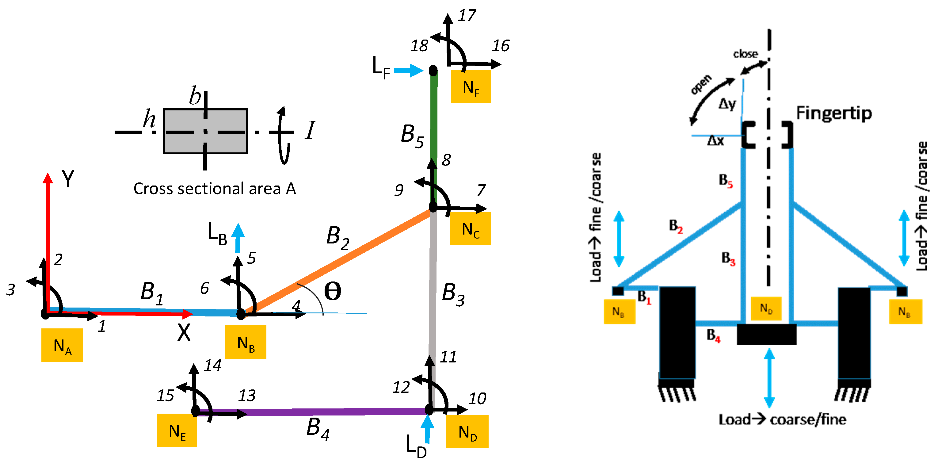
The fundamental structure depicted in
Figure 2 is crucial for understanding the deformation dynamics of the 3D gripper. By replicating this compliant mechanism in an arrayed configuration, the gripper achieves versatile grasping capabilities, similar to those found in prosthetics. A key aspect of the design is its ease of reconfiguration and manufacturability, enabling it to handle a wide range of objects effectively. As demonstrated in
Figure 1b, a prototype was fabricated using PolyJet technology, an advanced additive manufacturing process employed in Stratasys 3D printers. This method jets photopolymer droplets layer by layer, curing them with UV light to produce high-resolution parts with smooth surfaces and intricate geometries. PolyJet technology supports multi-material printing, allowing for components with diverse mechanical properties and textures, while removable support structures allow for the creation of complex designs. This makes PolyJet an ideal choice for high-accuracy prototypes, molds, and functional components.
The proposed compliant mechanism presents a number of functional advantages that enhance its applicability in robotic gripping systems. Its design is adaptable to both planar (2D) and spatial (3D) configurations, enabling flexibility in its use across different robotic platforms. The monolithic construction approach eliminates the need for assembly, simplifying the fabrication process and reducing potential sources of mechanical failure. Additionally, the mechanism can be fabricated using a wide range of materials—including soft polymers, composite blends, and biocompatible materials—allowing for customization based on the intended application environment. The ability to support multiple input modes facilitates both synchronized and independent fingertip movements, which are essential for multi-scale grasping tasks. The design is also inherently scalable, which extends its potential use from lightweight micro-manipulation tasks to more robust, heavy-duty operations. Given these features, the concept is well-suited to diverse applications, such as robotic arms in manufacturing, manipulators for vehicular systems, surgical micro-tools, electrically non-conductive grippers for use in scanning electron microscopy, and components of prosthetic hands.
2.2. Compliant Mechanism DesignAnalysis
This study presents an integrated methodological framework that combines hybrid kinematics with the Stiffness Matrix Method to model and optimize the deformation of compliant mechanisms under diverse conditions. A key innovation is the introduction of the Geometrical Ratio (GR) metric, which establishes a clear correlation between design inputs and output motions, enabling scalable and adaptable designs. The theoretical framework, grounded in the Stiffness Matrix Method and incorporating Euler–Bernoulli and Timoshenko beam theories, forms the foundation for the design and analysis of the compliant mechanism. The framework uses MATLAB R2022b to compute nodal forces, displacements, and moments, enabling accurate predictions of deformation and performance. The simulation results validate the design by evaluating its compliance and GR under varying inputs. This comprehensive approach ensures there is a strong connection between the design theory and practical applications, advancing the field of compliant mechanism design.
The Stiffness Matrix Method [
41] allows for the simulation of the static deformation experienced by the compliant frame mechanism under different boundary conditions and imposed inputs. This approach hinges on the linear elastic deflection attributed to the bending of two-dimensional beam elements. It adheres to the solutions of ordinary differential equations addressing sectional forces along either the Euler–Bernoulli or Timoshenko beam theories. In the structural modeling of 2D linkage mechanisms, the selection between Euler–Bernoulli and Timoshenko beam theories significantly influences the accuracy of the stiffness matrix method used to compute nodal displacements and internal forces. The Euler–Bernoulli beam theory, which assumes that the plane cross-sections remain perpendicular to the neutral axis after deformation and neglects shear deformation, is appropriate for slender beams where bending is the dominant mode of deformation. However, this assumption becomes inadequate for short or deep beams, where shear effects contribute meaningfully to the overall response. The Timoshenko beam theory addresses this limitation by incorporating shear deformation, thus providing a more accurate representation of beam behavior in geometries with lower slenderness ratios or in dynamic loading conditions. Therefore, for the high-fidelity modeling of 2D linkage mechanisms, particularly those involving complex load paths or geometrical configurations, the Timoshenko formulation is preferred, despite its increased computational complexity.
Each beam element is defined by two nodes, each associated with two orthogonal forces and a single rotational parameter based on their localized coordinates. The local stiffness matrix ‘k’ for each beam element can be deduced, which subsequently undergoes a transformation to align with the global XY coordinate system. Consequently, a global stiffness matrix ‘K’ is aggregated for a symmetric structure and inverted.
This inversion enables the calculation of nodal displacements and associated forces, encompassing horizontal (ux) and vertical (uy) shifts, rotational displacements (uθ), and forces like normal force (N), shear force (V), and moment (M).
The beam under consideration is presumed to have consistent elastic properties, denoted as {E,A,I}. Here, ‘E’ represents the modulus of elasticity, ‘A’ signifies the cross-sectional area, and ‘I’ refers to the second moment of the area.
The Stiffness Matrix Method (SMM) is a prominent tool within the domain of finite element analysis, and is particularly tailored to digital processing. Given its efficacy, there is often no pressing need to derive symbolic equations for intricate frames, such as the compliant structure illustrated in
Figure 2. Instead of delving into exhaustive analytical derivations, this document places a more substantial emphasis on the numerical implementation and consequent analysis.
The beam stiffness techniques applied in this study emulate the forces at the nodes and their respective displacements in response to external loading. These simulations operate under meticulously examined boundary conditions, ensuring they provide a true reflection of the underlying physics. Within the framework of the Stiffness Matrix Method, two primary vectors play a pivotal role: the load vector ‘P’ and its associated deflection vector ‘Δ’. Both vectors are integral to solving the equilibrium equation, offering insights into how the system reacts to various forces and constraints.
The term represents the cumulative fixed end actions resulting from the element loads across each Degree of Freedom (DOF). To ascertain both the reaction and internal forces, one can employ the solution for unknown deflection by implementing the equation {p} = [k]{δ} for every beam. Here, ‘p’ and ‘δ’ denote the element nodal force and displacement, respectively.
The mechanism highlighted in
Figure 2 consists of a statically indeterminate structure made up of five complaint beams, designated as B
1 through B
5, anchored at nodes N
A and N
E and subjected to external forces. When assembling symmetrical grippers using several mechanisms, the boundary condition at node N
D is restricted, specifically along the displacement coordinate-10.
We created a MATLAB program to simulate Equation (1); see the pseudo-code in
Appendix A. Each beam is defined by two nodes, and every node possesses three localized DOFs, corresponding to the normal force, shear force, and rotational moment. Each force aligns with a displacement along its respective axis, with the numbering system for these displacements maintaining consistency across all nodes, from N
A to N
F.
Two primary categories of external loads are under investigation in this study:
Axial force or displacement (LD) applied directly to node ND, known as the “Shuttle”.
Axial force or displacement (LB) exerted on node NB, termed the “Wing”.
Boundary conditions are set with fixed displacements at [NA, NE], alongside a restrained coordinate u10 at node ND. The conditions at the fingertip (node NF) are influenced by the rigidity of the object in its grasp. For instance, when engaging with a hard object, it is advisable to assign a zero value to the displacement coordinate u18. Conversely, as will be demonstrated, the SMM analysis proves beneficial in situations of soft object grasping. In such scenarios, both the normal force and displacement at the contact point are dictated by the combined compliance formed between the object and the fingertip. Additional boundary conditions could also encompass an external force, LF, applied directly to the fingertip.
3. Numerical Analysis
3.1. Geometrical Ratio-Driven Topological Analysis in Contact-Free Environments
This study predominantly focuses on the lateral displacement of the fingertip resulting from input displacements imparted either at the Shuttle node or the Wing node. In this section, we analyze the fingertip deflection in the absence of object contact.
Utilizing the Stiffness Matrix Method involves the application of the Euler–Bernoulli or Timoshenko beam theories, specifically for small deflections. Within this context, both the second moment of the area and the modulus of elasticity manifest in the global stiffness matrix, accounting for the beams comprising the structure. Here, we introduce the Geometrical Ratio (GR) as a dimensionless parameter, defined as the proportion of observed output displacement to the corresponding input displacement.
The kinematic assessment delineated in this segment scrutinizes the mechanism illustrated in
Figure 2, accompanied by the specific dimensions tabulated in
Table 1. It is assumed that all beams are constructed from a uniform material, characterized by a moment of area ‘I’ and consistent cross-sectional area ‘A’. Notably, the fingertips traverse freely, devoid of any contact with external entities.
To investigate the relationship between the angle θ and the GR under a uniform moment of area, we conducted two distinct simulation sets.
Numerical Example—In the first simulation, a unit input displacement load was applied upward at the Shuttle node, while measuring the lateral output displacement at the fingertip. As a result of this upward displacement, the fingertip opened in the opposite direction to that of coordinate-16.
Figure 3 illustrates the GR’s response to angle variations within the range [0, 90°]. Notably, the peak GR, approximately 1.36, was observed at an angle of roughly 76° due to the displacement of the input at the Shuttle.
Numerical Example—Conversely, the second simulation set, also displayed in
Figure 3, evaluated the GR’s reaction to a unit input displacement load directed upward at the Wing node. Here, the maximum GR reached about 1.46, occurring at an angle close to 60°.
The analysis presented in
Figure 3 suggests that, by strategically selecting the angle, it is feasible to merge both fine and coarse fingertip movements using two distinct inputs. Specifically, an equivalent response from a unit displacement input applied at either the Wing or the Shuttle occurs at an angle of 37°. Key angles, denoted as θ* = {37°, 60°, 70°}, will be the focal point in subsequent discussions.
From earlier simulations, we observed that applying an upward displacement at the Wing node NB caused the fingertip to open. However, we propose that this motion’s direction can be inverted to facilitate finger-closing without reversing the input load’s orientation. One approach, which we will demonstrate, is by amplifying the second moment of area for beam B4. By doing so, we not only reverse the motion but also enhance the gripper’s lateral stability and its resilience to upward movements.
To further our understanding, we analyzed the response ratio GR against varying angle θ using a unit input displacement at Wing node N
B. This procedure was then replicated for multiple moments of area for beam B
4. Introducing the term R, which denotes the ratio of beam B
4’s moment of area to that of other beams, it was observed that beams {B
1, B
2, B
3, B
5} maintain a consistent moment of area. The findings presented in
Figure 4 exhibit both positive and negative GR values, symbolizing the “open” and “close” modes, respectively. For instance, ratios R = {0.1, 1, 2} persistently exhibited the “open mode”, irrespective of angle θ. Conversely, other GR curves demonstrated shifts in motion direction. At a ratio of R = 8, a transition from “close mode” to “open mode” was observed at angle θ of approximately 55.5°.
In summary, the GR analysis underscores several benefits of our proposed mechanism. Notably, its adaptability enables the creation of grippers that can either open or close at multiple amplification ratios, spanning from coarse to intricate movements. Furthermore, given that not all actuators possess bidirectional capabilities, our design allows for an omnidirectional actuator to facilitate both opening and closing motions. Finally, Equation (1) posits that when beams are homogenously constructed with uniform cross-sectional areas, the resulting fingertip displacement, triggered by input displacements, remains dependent on the mechanism’s geometry, regardless of the material properties or cross-sectional area values.
3.2. Compliance Simulation Model in Contact-Free Environments
In this section, we conduct a numerical analysis of the finger’s behavior without any object interaction. The primary objective is to determine the mechanism’s equivalent stiffness, K, by observing the fingertip’s lateral displacement caused by an input force exerted either on the Wing or Shuttle node. Defined as the inverse of stiffness 1/K, compliance elucidates the propensity of the gripper’s structure to undergo deformation under an external force. For a gripper constructed from m symmetrically configured identical mechanisms, with the premise of symmetric boundary conditions, force FD, when applied to the Shuttle, will distribute as FD/m across each mechanism.
Numerical Example—Assuming the mechanism beams, as depicted in
Figure 2, maintain a uniform rectangular cross-sectional area and a consistent area moment of inertia, we aim to explore the linear elastic behavior of a single mechanism constructed from a material with a modulus of elasticity E = 3 GPa. The data in
Figure 5 adhere to the linear model presented in Equation (1). The gradient corresponds to the Shuttle and Wing compliances of the mechanism, denoted as C = {1/K
s, 1/K
w}, evaluated at the specific angles θ* addressed earlier. For instance, at angles θ* = {37°, 60°, 76°}, the compliance values C are {0.022, 0.004}, {0.030, 0.001}, and {0.017, 0.010} mm/g, respectively, yielding a compliance differential of (1/K
S − 1/K
W) = {0.018, 0.029, 0.007} mm/g.
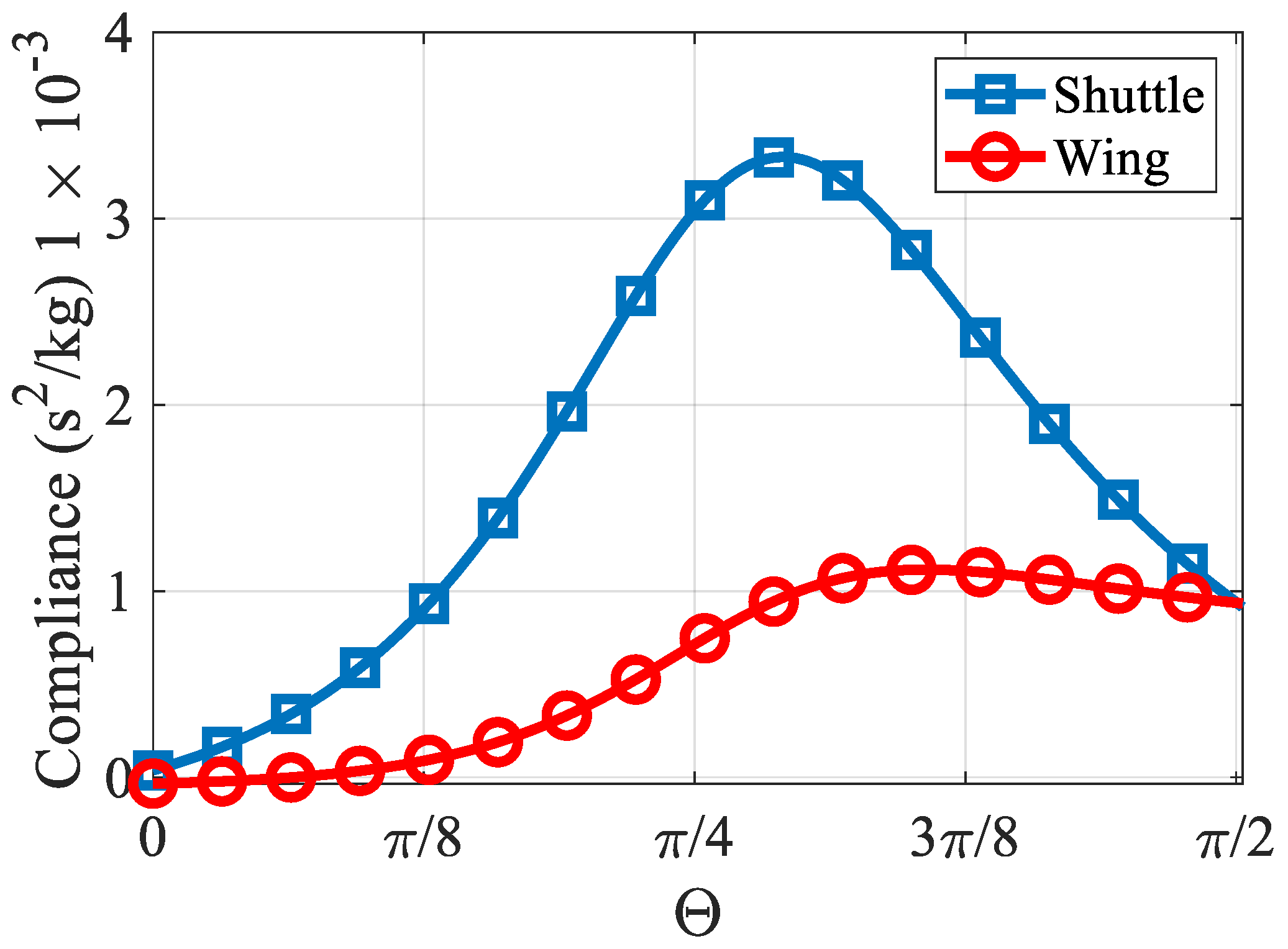
Further intensive simulation work probes into the compliance in relation to angle θ. Due to the linear nature of the mechanism, deriving the compliance requires dividing the fingertip’s lateral displacement by the applied unit force at the node. The observations from
Figure 6 infer that peak compliances for both the Shuttle and Wing manifest within the angle bracket θ~[52°–63°]. These compliance values correlate to the maximum lateral displacements that are observable at the fingertip for an input force of 1N at nodes N
D or N
B.
3.3. Modeling and Simulation of Rigid Contact Grasping
In this section, we examine the behavior of non-deformable fingertips in the act of grasping a solid object. Object manipulation involves the mechanical interplay between the object being manipulated and the overseeing medium. This interaction is profoundly shaped by the gravitational friction, electrostatic forces, and Van der Waals forces, especially when the object directly contacts a surface in a dry medium.
When placing an object within a gripper, outfitted with a symmetrical fingertip array, various factors determine the nature of the contact force and the magnitude of the contact pressure in a static equilibrium state. These factors include the flexibility of both the object and gripper, the frictional attributes of the contact surface, the area and number of contacts, and the force and direction of loads created at node(s) Nf from input loads.
Contact between the object and gripper usually occurs when the fingertip envelops the object, resulting in point contacts, line contacts, or surface contacts. Several potential contact models are suitable for this gripper’s operation, encompassing both frictional and frictionless point contacts between a combination of rigid and soft objects and anthropomorphic hard and soft fingertips. The significance of analyzing these contact models is to gain insights that aid in the design of the gripper considering specific load and boundary conditions. The elastic deformation that takes place during contact might result from the elasticity of either the object or the fingertip. A few examples of this include a soft anthropomorphic fingertip holding a rigid object or a pliable object being held by a hard fingertip.
To elucidate this, we conducted a simple case study that simulates the grasping action of a rigid fingertip coming into contact with a rigid object. We presumed the object to be spherical for simplification. It was sized so that it makes immediate contact with the fingertip without pre-stressing the structure. We also presumed a frictional point-contact type, achieving static equilibrium at node Nf. The fingertip can move along the u17 coordinate, is restricted on the u16 coordinate, and can rotate around the contact point. Based on this, the boundary conditions at the contact point are as follows:
Numerical Example—For our simulation, we utilized the dimensions from
Table 1, assigning the material an elasticity modulus of 3 GPa. We assumed the gripper was built using three identical mechanisms, adopting the dimensions from
Table 1. We set the angle θ to 45°. The input force load L
D was directed downwards, prompting the gripper to clasp the object, as illustrated in
Figure 7. Upon exerting an input load, beam B5 underwent a positional shift from the C-F axis to the C’-F’ axis. Assuming there was no sliding, the fingertip was postulated to undergo a rotation around a fixed contact point, with its lateral displacement manifesting tangentially to the C’-F’ axis. Consequently, the tangential and normal forces can be mathematically expressed as
and
, respectively. Here, angle
ψ symbolizes the rotational angle u
18 of N
f at node B5. This angle can be derived from the nodal solution of the Stiffness Matrix Method, as depicted in Equation (1). For this analysis, a conventional “friction cone” model, rooted in Coulomb friction’s point-contact theory, is employed. This method quantifies the permissible ratio of tangential to normal forces that can be maintained in the absence of slippage, as referenced in [
42,
43]. The tangential frictional force is then bounded by specific criteria:
where
μ denotes the Coulomb friction coefficient characterizing the interaction between the two contacting materials. In a different scenario, the absence of slipping is a condition that arises when
where
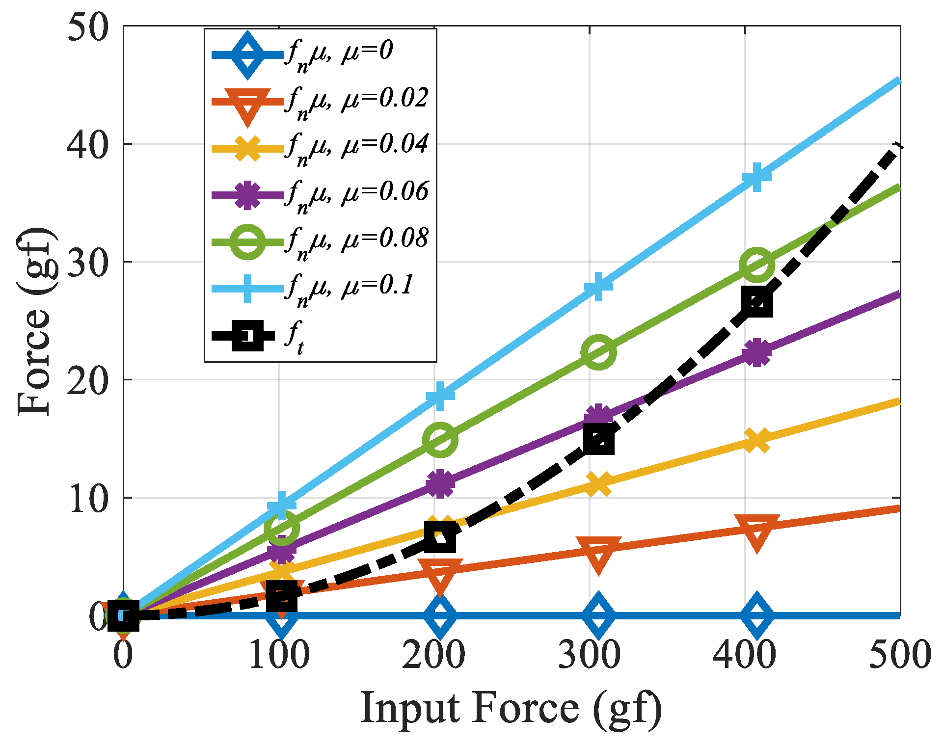
ψ is quantified in radian.,
Figure 8 provides simulation results depicting frictional force
ft and the permissible static friction force
μfn that result from the input force
LD exerted on the Shuttle. A condition of no slippage is ensured either when the criteria outlined in Equation (1) are met or when the values of
μfn surpass the
ft curve.
3.4. Modeling and Simulation of Deformable Contact Grasping
In this section, we examine the behavior of deformable fingertips in the act of grasping a solid object, as depicted in
Figure 9a. Elastic contact dynamics is a thoroughly investigated domain. Among the myriad of contact models, the classical Hertz contact model stands out, postulating that the contact area of a linear elastic material sphere correlates with the normal force to the 1/3 power [
42]. Subsequent models cater to non-linear elastic materials, and can be formulated for spherical fingertip shapes using power law dynamics. These models offer robust approximations, especially for softer fingertips reminiscent of rubber [
43].
This work presents a generalized framework for modeling deformable contact mechanics using a virtual elastic cantilever beam analogy, enabling the precise analysis of elastic contact behavior across diverse applications. By integrating linear elasticity principles and the Stiffness Matrix Method, it provides a systematic approach to determine equivalent stiffness, optimize contact forces, and predict displacements. For the current analysis, we assume a linear elastic contact model is being used. Our objective is to conceptualize a virtual elastic cantilever beam, referred to as B
6 in
Figure 9b,c. This beam serves as an analog to the elastic contact dynamics and is designed to meet the static equilibrium criteria. This approach facilitates the application of the Stiffness Matrix Method, as delineated in Equation (1).
Node NG anchors virtual beam B6, while its free end connects to node NF. Several assumptions underlie this model: the grasping action follows a frictionless point-contact paradigm, and any deformation at the point of contact is hypothesized to result in minimal rotation, maintaining the normal force orthogonal to the contact plane. Consequently, node NF undergoes translation along the u16 coordinate, inducing an internal shear force, V16, congruent with the normal contact force.
Initiating the simulation for this deformable contact scenario requires discerning both the physical and dimensional attributes of the virtual cantilever beam B
6. Envisioning a generic-shaped linear elastic fingertip exerting force against a rigid counterpart, we can derive the fingertip’s equivalent stiffness, k
f. This can be sourced from a rudimentary compression test that juxtaposes external load
P with displacements
δ. The stiffness parameter aligns with the deflection model of a linear elastic cantilever beam, as shown in
Figure 9b. Following this, the ideal length of the cantilever can be deduced using the subsequent relationship:
The modulus of elasticity for the fingertip, denoted as Ef, may differ from that of the mechanism, whereas I6 represents the moment of area for the cantilever beam. I6 was set such that the contact stiffness V16/u16 is equivalent to the stiffness kf for an applied load LD. The appropriate I6 value can be determined numerically by comparing it with the ratio V16/u16 and then selecting the I6 that equates to kf = V16/u16. Cross-sectional area A6 was derived based on the geometric assumptions made in the I6 calculations. Equation (4) implies that the contact dilemma can be approximated as a rigid-to-rigid interaction as kf approaches infinity.
The subsequent phase of the elastic contact assessment involves incorporating virtual beam B6 into the overall mechanism. The local degrees of freedom (19, 20, and 21) are constrained, and the Stiffness Matrix Method is applied to the entire assembly. Owing to the integration of the contact issue as a novel beam within the structure, the normal contact force at node NF becomes synonymous with the internal shear force V16.
Numerical Example—let force be exerted on the Shuttle of a single mechanism. Assume the boundary conditions at node NF allow for unrestrained displacements. The beams adopt a rectangular cross-section, labeled A, with a modulus of elasticity of 3 GPa. Both the fingertip stiffness k
f, and its elasticity modulus were set at 1000 N/m
2 and 0.1 MPa, respectively. The revised cross-sectional area for the virtual beam is A
6 = α
2A. Alternatively, the moment of area can be adjusted, I
6 = α
2I, with A and I derived from the dimensions in
Table 1.
The analysis’s subsequent stage determines the value of α to equate the contact stiffness k
f with the fingertip stiffness of 1000 N/m.
Figure 10a displays a correction factor α = 0.329 that fulfills the equality condition. Using Equation (4), the resultant beam length L
6 was determined to be 0.219 mm.
These findings are employed to formulate the {B1 to B6} assembly matrix. Simulations are conducted for a load
LD directed downward onto the Shuttle, in the range [0, 98] gf. A sample displacement graph is illustrated in
Figure 9d. The normal forces (V
16) in relation to the L
D vector are captured and juxtaposed with node N
F’s displacements, as depicted in
Figure 10b. The minimal rotation values confirm the point-contact hypothesis. Under the assumed normality in this model, node N
F continues its vertical displacement. However, as friction is excluded, this movement bears no relevance to friction, signifying the synchronized movement of the structure and the solid object, while the normal force remains orthogonal to the tangent plane.
4. Experiment
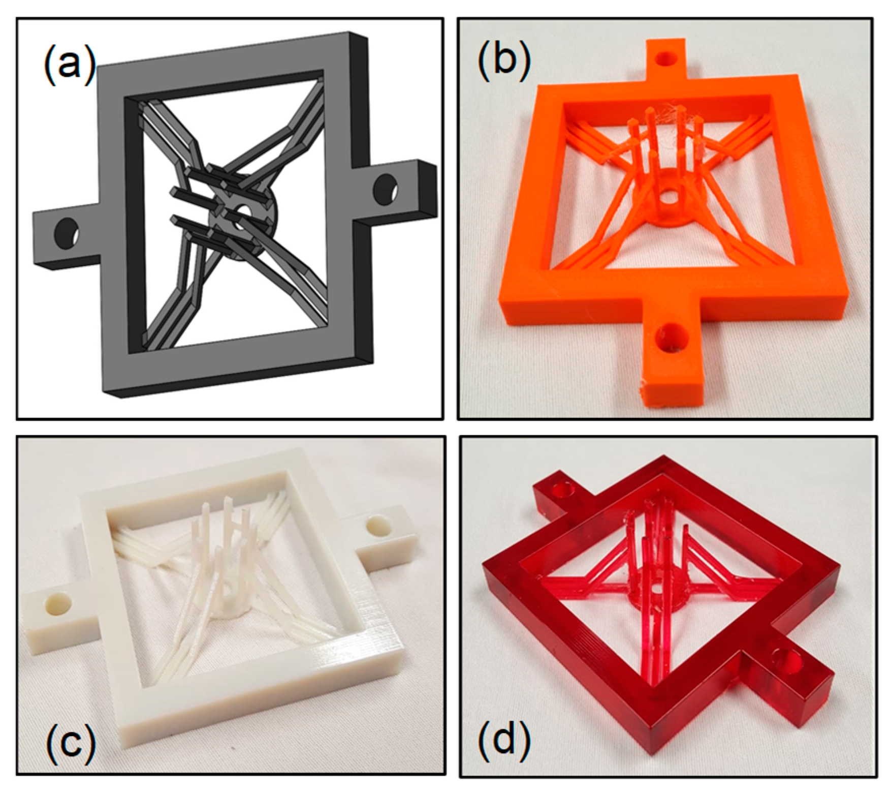
The aim was to compare the experimental and simulation results, specifically the input-to-output displacements across grippers made with different 3D printing methods, to assess any manufacturing impact despite the identical design and input conditions. The gripper design is compatible with various additive manufacturing techniques, such as SLA, FDM, and SLS, which align with the analysis by accurately replicating the elastic and continuum deformation critical to its performance. Experiments were conducted to validate the viability of designing grippers using the proposed mechanism, with the primary objective of juxtaposing the simulation outcomes with the experimental results concerning the GR. Quadratic-fingered multi-finger grippers, as depicted in
Figure 11, exemplify the potential forms these grippers can assume. Dimensions pertinent to each mechanism within the gripper are detailed in
Table 1.
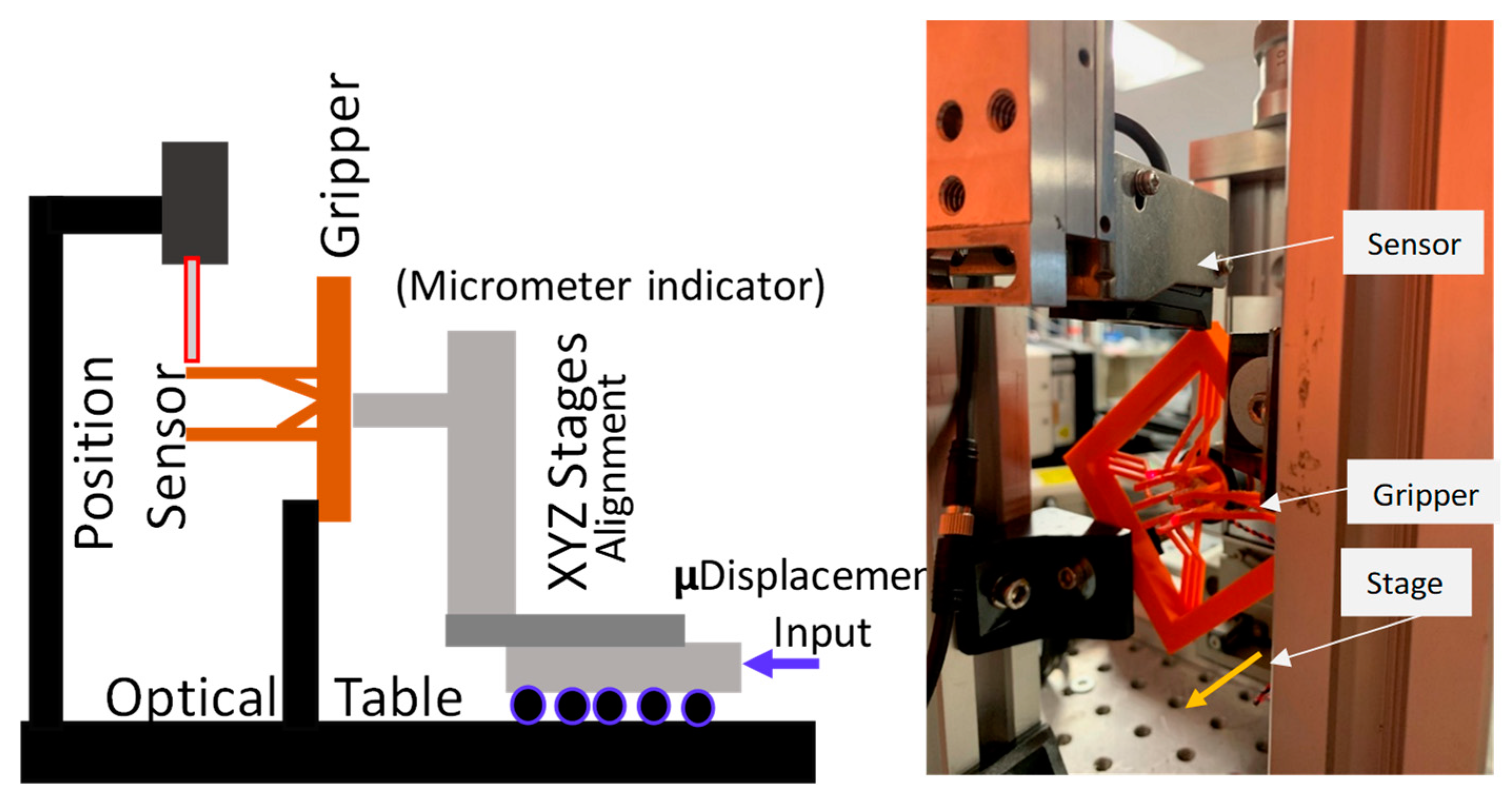
The experimental procedure for data acquisition was conducted using a high-precision testing setup, as illustrated in
Figure 12. The setup consisted of a linear micro-stage (Manufactured by Melles Griot, California USA, with 1 μm positional accuracy) to deliver controlled input displacements to the Shuttle node (N
D), an infrared position laser sensor head (Keyence IL-030, Manufactured by Keyence Corporation, Osaka, Japan) with a sampling rate of 1 ms and a resolution of 0.1 μm for displacement measurements, and a stably mounted gripper to maintain alignment and stability throughout the experiment. During the experiment, the linear micro-stage applied precise displacements to N
D, and the resultant fingertip displacements were measured using the laser position sensor. Each displacement measurement was repeated three times to minimize experimental error, with the averaged values recorded for analysis. Given the symmetrical kinematic response of the fingertips to an upward input load, the nodal displacement of N
D in the u
10 direction was assumed to be negligible, simplifying the experimental model and allowing for a focused evaluation of fingertip displacement behavior.
The initial simulations for the GR were executed over a displacement range of u
11 = [0, 1] mm. Using the Stiffness Matrix Method, grounded in Euler–Bernoulli beam theory, the lateral displacement of the fingertip, representative of node N
F’s deflection in the u
16 direction, was simulated and the outcomes were charted in
Figure 13. A resultant GR of 0.88 was discerned from the trend line’s gradient.
Subsequent experiments spanned various materials and employed FDM and polyjetting prototyping techniques. The fingertip’s displacement was assessed over a consistent input displacement range [0, 1] mm, with increments of 0.1 mm, with three data points captured for each specific displacement. Linear relationships between inputs and outputs were evident, as highlighted by the error plots in
Figure 13. Two distinct grippers were 3D-printed via the Stratasys Objet260 Connex3 polyjet printer (manufactured by Stratasys Ltd, Eden Prairie, MN, USA) using different elasticity moduli: one from VeroMagenta resin (2000–3000 MPa, depicted in
Figure 11d), and the other from DM8515 resin (1700–2300 MPa, shown in
Figure 11c). Another gripper, showcased in
Figure 11b, was fabricated from PLA using FDM technology (specifically the MakerBot Method) with an elasticity modulus of 2600 MPa.
When these displacement inputs were plotted, as presented in
Figure 13, the slopes of the trends were indicative of the GR values. Notably, the GR values for VeroMagenta, DM8515, and PLA were 0.80, 0.82, and 0.99, respectively.
Close scrutiny of
Figure 13 reveals a minuscule discrepancy between the simulated and experimental GR values within a constrained input range, underpinning the accuracy of the previous kinematic analysis and the assertion that GR remains unaffected by material attributes. It is worth noting that PolyJet printing yields fully solid structures, which likely accounts for the minimal variance between their GR values, making them more aligned with the theoretical expectations.
In contrast, the slightly anomalous GR value associated with the PLA gripper can be attributed to the inconsistent material extrusion intrinsic to the FDM printing process. This irregularity might result in structures with a diminished density and moment of area relative to the original design, leading to diminished resistance, augmented displacement, and consequently, a heightened GR value.
To address the influence of manufacturing anisotropy, especially in Fused Deposition Modeling (FDM), we provide additional detail on the printing orientation and parameters used in fabricating the compliant grippers. It is well-established that the build orientation can significantly affect the mechanical properties of printed structures due to the directional nature of layer deposition in additive manufacturing. Therefore, consistent orientation strategies were adopted to minimize variability and improve comparability across printed samples.
For PolyJet-printed prototypes (Stratasys Objet260 Connex3), the grippers were printed in a horizontal orientation, where the fingertip plane and compliant beams lay parallel to the build platform (XY-plane). This setup ensures uniform material deposition across the beam length and minimizes support contact on functional surfaces. The layer resolution was set at 16 µm with full-density solid fill using VeroMagenta and DM8515 materials. Support material was automatically generated by the GrabCAD Print software Version 1.70 and removed using water jet-cleaning.
For FDM-printed prototypes (MakerBot Method, PLA material), the grippers were also printed in a horizontal orientation to ensure that the compliant beams were aligned in the XY-plane, while the Z-axis represented the out-of-plane build direction. This strategy helps reduce anisotropic weakening along the bending direction. The slicing parameters included a 0.2 mm layer height, 100% infill density, and a linear infill pattern, using standard PLA settings with a consistent extrusion temperature and cooling fan settings across prints.
By controlling the orientation and print settings, we ensured that comparisons between simulations and experiments reflected the structural design differences rather than fabrication-induced variability. These details provide a clearer understanding of how anisotropy was managed and support the validity of the experimental data presented.
In conclusion, the experimental validation closely aligns with simulations, with variations attributed to the manufacturing processes; PolyJet printing ensures consistent material properties matching the simulations, while FDM introduces irregularities that affect density and performance, emphasizing the impact of fabrication methods on the design accuracy.
5. Discussions
This study presents a novel framework for the design, modeling, and validation of a multiscale-compliant gripper based on a topologically optimized structure, aimed at enabling integrated precision and coarse robotic manipulation. The gripper design employs a symmetrical five-beam compliant mechanism fabricated via additive manufacturing and modeled using the Stiffness Matrix Method (SMM). This modeling framework incorporates both Euler–Bernoulli and Timoshenko beam theories, providing the flexibility to capture the mechanical behavior of both slender and moderately thick beams under linear elastic deformation. The modular design supports a wide range of geometrical configurations and loading conditions, thereby ensuring its scalability and adaptability across diverse robotic applications.
A key innovation in this work is the introduction of the Geometrical Ratio (GR), defined as the ratio of fingertip displacement to applied input displacement. Parametric simulations revealed that GR is predominantly influenced by geometric parameters—such as beam angle and moment of inertia distribution—rather than by material properties. This observation has significant implications: it enables a design process that is both material-independent and manufacturable using a variety of additive technologies. By adjusting design parameters, such as the angle between beams B1 and B2 or the moment of inertia of beam B4, the direction and magnitude of the fingertip motion can be precisely tuned. Notably, the design allows for motion reversal without changing the actuation direction, making it well-suited for integration with unidirectional actuation sources, such as thermal, pneumatic, or shape-memory alloy-based systems.
Under contact-free conditions, the compliant mechanism exhibited predictable kinematic responses characterized by design-dependent GR and compliance profiles. The simulation results identified optimal angular configurations, particularly within the range of 52° to 63°, that maximize fingertip displacement and mechanical compliance. Under contact-rich scenarios, the gripper’s performance was analyzed using two models: a rigid contact model based on Coulomb friction theory and a deformable contact model using a virtual cantilever beam. The deformable contact model, integrated seamlessly into the global stiffness formulation, enables the efficient and accurate simulation of fingertip–object interactions without resorting to non-linear contact mechanics. This hybrid approach allows the compliant gripper to adapt to both rigid- and soft-object manipulation tasks, thereby extending its functional applicability.
Experimental validation was conducted using prototypes fabricated via two additive manufacturing techniques: Fused Deposition Modeling (FDM) and PolyJet printing. The experimental results confirmed the reliability of the modeling framework, with PolyJet-printed grippers exhibiting GR values that closely match the simulation predictions. The consistency is attributed to PolyJet’s superior resolution and material homogeneity. FDM-printed grippers showed slightly higher GR values due to the material deposition variability and lower dimensional accuracy, which influence cross-sectional stiffness and elastic response. These findings emphasize the importance of fabrication fidelity in the performance of compliant mechanisms, particularly in applications requiring repeatable and precise deformation responses.
The monolithic nature of the proposed gripper eliminates the need for conventional assembly processes, reducing mechanical failure points and simplifying the manufacturing process. The design also supports independent and synchronized fingertip control, enabling multiscale grasping without additional actuation complexity. Collectively, the presented methodology demonstrates a compelling pathway for developing compliant end-effectors that are lightweight, structurally robust, and easily customizable. The gripper’s ability to operate across meso-, micro-, and potentially nanoscale regimes highlights its relevance for applications in micro-assembly, biomedical devices, minimally invasive surgery, and precision manufacturing.
Future work will focus on extending this framework to incorporate dynamic modeling and real-time control through embedded sensing and actuation. Incorporating feedback mechanisms and intelligent controllers will enable closed-loop operation, facilitating adaptive and autonomous manipulation. Additionally, investigating the gripper’s performance under dynamic loading, fatigue, and time-dependent material effects (e.g., viscoelasticity) will provide deeper insights into its long-term reliability and practical deployment in robotic systems.
6. Conclusions
This research establishes a robust and analytically grounded methodology for the design and analysis of a multiscale-compliant gripper capable of both precision and coarse manipulation. The gripper structure, composed of a five-beam symmetrical compliant mechanism, was developed using topological optimization and modeled via the Stiffness Matrix Method with beam-theory-based formulations. A significant advancement introduced in this study is the Geometrical Ratio (GR), a geometry-driven, material-independent performance metric that enables scalable design and programmable fingertip motion through purely structural modifications.
Through systematic parametric analysis, the study identified optimal geometries for maximizing displacement and controlling motion direction without altering actuator inputs. The modeling framework was further extended to include both rigid and deformable contact scenarios using a novel virtual cantilever beam representation of fingertip compliance. This unified approach allows for the efficient and accurate modeling of fingertip–object interactions in both soft and rigid grasping applications.
Experimental validation using FDM and PolyJet-fabricated prototypes confirmed the accuracy and applicability of the simulation results. The PolyJet-based grippers demonstrated excellent agreement with the theoretical predictions due to their high material uniformity and dimensional precision, whereas the minor deviations observed in the FDM prototypes underscore the influence of manufacturing variability on compliant mechanism performance.
The proposed design is easily manufacturable using various additive techniques, structurally efficient due to its monolithic form, and adaptable to applications requiring compliant, precise actuation. Its geometry-driven performance enables scalable, material-independent customization, laying the foundation for the future integration of sensing, control, and autonomous operation in dynamic environments.


