Article

Research on Sensorless Technology of a Magnetic Suspension Flywheel Battery Based on a Genetic BP Neural Network

School of Electrical and Information Engineering, Jiangsu University, Xuefu Road 301, Zhenjiang 212013, China
*
Author to whom correspondence should be addressed.
Actuators 2025, 14(4), 174; https://doi.org/10.3390/act14040174
Submission received: 15 February 2025 / Revised: 27 March 2025 / Accepted: 31 March 2025 / Published: 2 April 2025

Abstract

:
The research object of this paper is a new type of multi-functional, air-gap-type, vehicle-mounted magnetic suspension flywheel battery. It is a new energy storage technology with a long working life, high energy conversion efficiency, multiple charging and discharging times, low carbon and environmental protection. However, when the vehicle-mounted flywheel battery is operating, it will inevitably be disturbed by road conditions, resulting in loose sensors and feedback errors, thereby reducing the control accuracy and reliability of the system. To solve these problems, a sensorless control system came into being. It samples the current of the magnetic bearing coil through the hardware circuit and converts it into displacement for real-time control, eliminating the risk of sensor failure. However, the control accuracy of the traditional sensorless system is relatively low. Therefore, this paper adopts a BP (backpropagation) neural network PID controller based on genetic algorithm optimization on the basis of the sensorless control system. Through the joint simulation of the dynamic simulation software ADAMS/VIEW2018 and MATLAB2022b, the optimal PID control parameter database for complex road conditions is established. Through sensorless technology, the current of the flywheel battery is converted into the position error for extensive training so that the genetic BP neural network PID controller can accurately identify the current complex road conditions according to the position error, so as to provide the optimal PID control parameters corresponding to the road conditions to carry out accurate real-time stability control of the flywheel rotor. The experimental results show that the method can effectively reduce feedback errors, improve the control accuracy, and output optimal control parameters in real time under complex road conditions, which significantly improves the reliability and control performance of the vehicle flywheel battery system.

1. Introduction

The magnetic suspension flywheel battery, also known as flywheel energy storage system. As a green physical battery, it breaks through the limitations of traditional chemical batteries [1]. It exhibits advantages such as high energy-storage conversion efficiency, long lifespan, absence of pollution, and short charging time [2]. The application of the flywheel battery to the field of electric vehicles can not only extend the life of the prime power battery but also improve the power performance and endurance of electric vehicles [3,4]. At present, the control system of the vehicle-mounted flywheel battery is mainly based on a sensor control system [5]. This control system relies on the displacement sensor to feedback the rotor changes. The position error data of the flywheel rotor is transmitted to the controller, and then the controller adjusts the magnetic suspension bearing to stabilize the flywheel rotor. At present, there are three common displacement sensors: eddy current, capacitive, and photoelectric. However, sensor-based control systems are greatly affected by the environment, especially when the vehicle is driving on some of the more complex road conditions [6]. When the sensor in the sensing control system fails, it will cause errors in the feedback data. These errors will greatly reduce the control effect of the entire control system. Secondly, the price of the sensor is expensive, and the installation is difficult, so the reliability is greatly reduced. In order to overcome the high cost of sensors in the sensor control system, the installation environment is affected by limiting factors such as the influence of magnetic bearing structure. The advent of sensorless control systems allows for reliable control at low cost without the need to install sensors [7]. This technology effectively avoids feedback errors of the sensor in the onboard flywheel battery system in more complex road conditions. It not only reduces the cost of the entire control system but also further enhances the reliability of the flywheel battery [8,9].
Although sensorless technology can reduce costs and reduce the problems caused by the failure of displacement sensors, the control precision of non-sensing technology is not as high as that of traditional sensing technology. The sensorless technology adopted in this paper is to sample the current flow of the magnetic bearing coil through hardware circuit and then convert it into displacement, feeding it back to the controller for real-time control. The data directly transmitted to the controller is divided into two steps for conversion. The first step samples the current of the flywheel battery’s magnetic bearing coil, and the second step converts the sampled current into the position error of the flywheel rotor. This indirect conversion will inevitably further amplify the error of the data. The control accuracy is reduced. Secondly, the application scenario of sensorless technology is more complicated [10]. Sensorless technology is designed to solve the problem of sensor failure caused by complex road conditions. More complex road conditions put forward higher requirements for the flywheel battery control system [10,11,12,13]. In analyzing the influence of complex road conditions on vehicle-mounted flywheel batteries, most of the existing studies have adopted the method of analyzing different road conditions separately [14]. The dynamic models of the flywheel battery under different road conditions were established separately. The adjustment algorithm for control parameters is summarized using the curve fitting method, and the control parameters of the controller are adjusted in real time [15]. However, the analysis process of this method is very complicated. It is necessary to summarize and fit the optimal controller parameters under each road condition, and the control system still adopts the traditional PID controller. The real-time and tracking nature of the control system cannot be guaranteed.
In order to improve the control performance of the traditional PID controller, most of the existing research uses neural network methods to optimize the PID controller [16,17,18]. Neural networks have strong nonlinear approximation abilities and learning abilities, and their structure and learning algorithms are simple and clear [19]. Therefore, the indirect self-tuning control strategy produced by combining the neural network algorithm with PID control can automatically adjust the parameters of the controller. The optimal combination of PID control is realized to make the system run with better performance. Neural networks also have some problems, such as their convergence process, which has two significant defects. First, the convergence speed cannot be guaranteed, usually requiring thousands of iterations or more. Secondly, it is easy to fall into local minima due to the improper selection of initial weights in training. In addition, there is no recognized theoretical derivation for setting network structural parameters and operational parameters, which are often selected according to experience. Once the selection is improper, the system performance will deteriorate and even lead to failure of convergence.
In order to solve the above problems, this paper adopts a BP neural network based on genetic algorithm optimization to optimize the PID controller. The current sampled by the hardware circuit is trained and fitted. When the vehicle-mounted flywheel battery meets the corresponding complex road conditions, the optimal control parameters are output in real time. Additionally, this data fitting link can reduce the error of the displacement data fed back to the control system so as to improve the precision of the sensorless control system. The introduction of the genetic algorithm can overcome the limitations of the BP algorithm to some extent. In the process of optimization, the genetic algorithm randomly generates multiple starting points in the high-dimensional feasible solution space and starts searching at the same time, and the search direction is guided by the fitness function. Therefore, the search area is wide, and the search efficiency is high. Introducing the genetic algorithm into neural network PID control and improving the performance of neural network PID control can accelerate the learning speed and improve the learning precision.
In conclusion, this study takes a multi-functional air-gap vehicle-mounted flywheel battery with a special structure as the controlled object and proposes a sensorless technology based on a genetic BP neural network PID controller. This algorithm aims to solve the following three key problems: (1) How to explore the vibration mechanism of the flywheel battery under continuous road disturbance. (2) How to achieve a low-cost and high-performance sensorless control system for the vehicle-mounted flywheel battery. (3) How to determine the structural parameters of the genetic BP neural network model by means of offline training. To solve the above three key problems, this article first analyzes the principle of traditional sensorless technology and designs the hardware circuit of the displacement self-detection circuit. Secondly, the technology of the genetic BP neural network PID controller is proposed and analyzed in detail. Finally, taking the road condition of continuous speed bumps as an example, simulation and experimental verification were carried out.

2. Overall Structure and Basic Principle of Magnetic Suspension Flywheel Battery

The control object of this paper is a multi-functional air-gap-type vehicle-mounted magnetic suspension flywheel battery, and its overall structure is shown in Figure 1. It includes a highly integrated 5-DOF (five-degree-of-freedom) hybrid magnetic bearing, a bowl-mounted flywheel, an external rotor brushless DC (direct current) motor, a protective housing, and three sets of displacement sensors.
The structure of the 5-DOF magnetic bearing is shown in Figure 1. The magnetic bearing in the traditional five-degree-of-freedom flywheel battery is controlled by three independent stators, with low integration, a scattered structure, and a large volume. If the stator can share the permanent magnet and control the radial and axial magnetic circuits without coupling, the volume of the magnetic bearing will be greatly reduced, and the overall integration will be improved. It is well known that when two stators with different degrees of freedom share the permanent magnet, if no effective measures are taken, the magnetic circuit will have a serious coupling phenomenon. Therefore, the research object of this paper adopts an innovative magnetic bearing structure design, in which the design of the axial part is key to the design of the overall magnetic bearing. The main permanent magnet, the secondary permanent magnet, and the multi-functional air gap cooperate with each other to achieve a highly integrated magnetic bearing with almost no coupling of any magnetic circuits. The magnetic circuit diagram of the axial and torsional hybrid magnetic bearings is shown in Figure 1.
As shown in Figure 1, the green arrow marks the static bias flux magnetic circuit of the hybrid magnetic bearing. Since the auxiliary permanent magnet guides the magnetic circuit, most of the magnetic circuit generated by the N pole of the main permanent magnet will flow to the S pole of the auxiliary permanent magnet. The overall direction will flow through the axial stator, flywheel, and torsion stator pole according to the design requirements, and finally reach the S pole of the main permanent magnet to form an axial closed loop. The axial control flux and the torsion control flux have no contact and are two independent closed loops. The axial control flux can adjust the axial position of the flywheel, and the torsion control flux can control the torsion deviation of the flywheel. This new type of hybrid magnetic bearing has a high degree of integration and control magnetic circuit coupling. This is mainly thanks to the multi-functional air gap in the axial part.
As the name implies, the multifunctional air gap has multiple functions for the overall prototype [20]. Its functions are mainly manifested in three aspects. First, the auxiliary permanent magnet is used to guide the magnetic circuit to the axial air gap, while the air gap is minimized. Secondly, the multifunctional air gap provides a complete circuit for the control magnetic circuit, making it completely separate from other control magnetic circuits and avoiding coupling. Finally, by adding a multifunctional air gap, the axial and torsion stators can share the permanent magnet for integration. In order to achieve the above functions, it is necessary to optimize the three air gaps and find a group that meets both the load-bearing capacity requirements and the stability control. At the same time, the combination of different degrees of freedom decoupling control can be realized, and the coupling of five degrees of freedom can be minimized.

3. Principle of Sensorless Technology of Magnetic Suspension Flywheel Battery

At present, there are two main research directions of displacement self-detection technology: the parameter estimation method and the state estimation method, with the parameter estimation method being the most widely studied internationally. Among them, Matsuda et al. proposed a pulse-width modulation signal test method [21]. This method is to estimate the inductance of the coil according to the pulse-width modulation signal of the power amplifier. Therefore, the switching power amplifier is required to provide the carrier signal for the rotor displacement information, which is mostly suitable for medium- and high-power occasions. On the basis of the basic principle of the pulse-width modulation signal test method, this paper proposes a new type of AC (alternating current) magnetic bearing displacement self-detection technology, where the three-phase inverter driven coil current ripple is a function of the rotor displacement. Secondly, because the control object of this paper is the vehicle-mounted magnetic suspension flywheel battery, its application environment is very complicated. When the vehicle is driving under more complex road conditions, the operation of the vehicle-mounted flywheel battery will be accompanied by some mechanical vibration, which will lead to the vibration of the flywheel battery shell. Since the displacement sensor is installed on the outer shell, it is inevitable that some sensors will become loose. These factors will cause large errors in the feedback data of the displacement sensor, which will affect the overall performance of the control system. Therefore, unlike traditional sensorless technology, the sensorless technology studied in this paper needs to take into account the factors affecting road conditions. This sensorless technology will be analyzed in detail below.

3.1. Basic Principle of Sensorless Technology

The displacement detection system is an important part of the entire magnetic bearing control system, which provides real-time rotor position feedback signal to the controller to form a stable closed-loop control system. However, the introduction of displacement sensors will not only increase the cost but also affect the overall performance of the system. Because the control object of this paper is a vehicle-mounted magnetic suspension flywheel battery, its application environment is very complicated. When the vehicle is driving under more complex road conditions, the operation of the vehicle-mounted flywheel battery will be accompanied by some mechanical vibration, which leads to the vibration of the flywheel battery housing. Since the displacement sensor is installed on the housing, it is inevitable that some sensors will become loose. These factors will cause a large error in the feedback data of the displacement sensor and affect the overall performance of the control system.
The vehicle driving on an uneven road surface will have a significant impact on the vehicle-mounted flywheel battery control system, especially the sensor control system. When the vehicle experiences severe vibrations, the vibrations are transmitted to the housing of the vehicle-mounted flywheel battery, potentially causing the sensor mounted on the housing to loosen or even wear. This will have a significant adverse effect on the accuracy of the displacement data fed back by the sensor. Therefore, in order to study the impact of vibration on the sensor, the sensor reliability pre-test of the flywheel battery was first conducted on the vibration exciter experimental platform, as shown in Figure 2. The flywheel battery speed set in the experiment was 5000 r/min. When a single vibration is generated by a shaker, the sensor will loosen at about 600 vibrations. When the vibration exciter is used to generate double vibrations, the sensor will loosen at about 540 vibrations. The displacement deviation caused by the loosening of the sensor is about 0.03 mm, as shown in Figure 3. A deviation of 0.03 mm will have a significant impact on the accuracy of the control system, which will lead to the instability of the flywheel battery rotor.
At present, there are two types of sensorless technologies for magnetic suspension flywheel batteries: parameter estimation method and state estimation method. Currently, most control systems use the parameter estimation method, which includes the pulse-width modulation signal test method. This method estimates the inductance of the coil from the pulse-width modulation signal of the power amplifier. Based on the pulse-width modulation signal test method, a new sensorless technique is proposed, where the control current ripple of flywheel battery magnetic bearing coil is a function of rotor displacement.
The connection between the magnetic bearing coil load of the magnetic suspension flywheel battery and the inverter is shown in Figure 4.
In order to introduce the principle of sensorless technology, the radial coil of a 5-DOF magnetic bearing system is used as an example. In Figure 4, the resistors Ra, Rb, and Rc represent the resistance of the magnetic bearing three-phase coil. Inductance La, Lb, and Lc represent the inductance of the magnetic bearing three-phase coil. Ua, Ub, and Uc are the phase voltages of the three-phase coil, and the phase delay is 120° in turn. Ia, Ib, and Ic are the phase currents of the three-phase coil. Let the position error of the rotor along the positive direction of the x axis and the y axis be x and y, respectively. The phase voltage equations of the three-phase coil can be expressed as follows:
U a = R a I a + d L a I a d t = R a I a + L a d I a d t + I a d L a d t U b = R b I b + d L b I b d t = R b I b + L b d I b d t + I b d L b d t U c = R c I c + d L c I c d t = R c I c + L c d I c d t + I c d L c d t
Because the inverter switching frequency is very high, so dIj/dt >> dLj/dt and LjdIj/dt >> RjIj, where j = a, b, c, the above equation can be approximated as follows:
U a L a d I a d t U b L b d I b d t U c L c d I c d t
According to electrical engineering knowledge, the inductance coefficient can be expressed as follows:
L = N 2 R m
In the equation, N is the number of coil turns and Rm is the total magnetoresistance of the magnetic circuit. Under the consideration of a small air gap δ, as well as neglected iron losses and neglected saturation of the iron core, Rm is the sum of the magnetic resistance of the core, the air gap, and the rotor:
R m = i = 1 n L i μ i S i + 2 δ μ 0 S
In the equation, Li is the length of each iron core. μi is the relative permeability of each core. Si is the cross-sectional area of each core. δ is the length of the air gap under the magnetic pole. μ0 is the vacuum permeability. S is the magnetic pole’s cross-sectional area.
Since μi >> μ0, compared to the air gap, the magnetoresistance of ferromagnetic materials is negligible. The magnetic potential all falls on the air gap, and the magnetoresistance under the three magnetic poles can be expressed as follows:
R m 2 δ μ 0 S
By substituting Equation (5) into Equation (3), the inductance of the three-phase coil can be obtained:
L a μ 0 N 2 S 2 ( δ 0 x ) L b μ 0 N 2 S 2 ( δ 0 + 1 2 x 3 2 y ) L c μ 0 N 2 S 2 ( δ 0 + 1 2 x + 3 2 y )
From Equations (2) and (6), the approximate expression for the phase current of the three-phase coil can be obtained as follows:
I a 1 L a U a d t = 1 μ 0 N 2 S ( δ 0 x ) U a d t I b 1 L b U b d t = 1 μ 0 N 2 S ( δ 0 + 1 2 x 3 2 y ) U b d t I c 1 L c U c d t = 1 μ 0 N 2 S ( δ 0 + 1 2 x + 3 2 y ) U c d t
The phase voltage of a three-phase coil is obtained by Fourier expansion:
U a = 4 U d π sin ω s t + 1 3 sin 3 ω s t + 1 5 sin 5 ω s t + U b = 4 U d π sin ω s ( t 120 ) + 1 3 sin 3 ω s ( t 120 ) + 1 5 sin 5 ω s ( t 120 ) + U c = 4 U d π sin ω s ( t + 120 ) + 1 3 sin 3 ω s ( t + 120 ) + 1 5 sin 5 ω s ( t + 120 ) +
In Equation (8), ωs is the fundamental frequency of the PWM. The higher harmonics in the phase voltage can be filtered through the band-pass filter with the center angular frequency of ωs. It can be obtained by integrating with Equation (7):
I a 1 μ 0 N 2 S 4 U d π ω ( δ 0 x ) cos ω s t I b 1 μ 0 N 2 S 4 U d π ω ( δ 0 + 1 2 x 3 2 y ) ( 1 2 cos ω s t 3 2 sin ω s t ) I c 1 μ 0 N 2 S 4 U d π ω ( δ 0 + 1 2 x + 3 2 y ) ( 1 2 cos ω s t + 3 2 sin ω s t )
After the demodulation circuit processing, that is, Equation (9) on the right-hand side of the equation multiplied by the unit cosine signal, can be obtained:
I a 1 μ 0 N 2 S 4 U d π ω ( δ 0 x ) ( 1 2 + cos 2 ω s t 2 ) I b 1 μ 0 N 2 S 4 U d π ω ( δ 0 + 1 2 x 3 2 y ) ( 1 4 + cos 2 ω s t 4 3 4 sin 2 ω s t ) I c 1 μ 0 N 2 S 4 U d π ω ( δ 0 + 1 2 x + 3 2 y ) ( 1 4 + cos 2 ω s t 4 + 3 4 sin 2 ω s t )
After processing by the low-pass filter circuit, the high-frequency component is filtered to obtain the DC signal:
I a 1 μ 0 N 2 S 4 U d π ω ( δ 0 x ) 1 2 I b 1 μ 0 N 2 S 4 U d π ω ( δ 0 + 1 2 x 3 2 y ) 1 4 I c 1 μ 0 N 2 S 4 U d π ω ( δ 0 + 1 2 x + 3 2 y ) 1 4
Equation (11) can be obtained by solving the following equations:
x 4 3 K ( I b + I c I a ) y 4 3 K ( I c I b )
In Equation (12), K = 4Ud/μ0N2Sπω. According to Equation (12), the change in phase current of three-phase coil reflects the change of rotor air gap. The three-phase current is demodulated and filtered by the signal demodulation circuit. A DC signal proportional to the rotor displacement signal can be obtained. The displacement signal detection circuit uses an analog circuit to realize the phase current band-pass filtering, demodulation and low-pass filtering. The displacement of the rotor from the balanced position in the magnetic bearing system is obtained indirectly and provided to the input end of the controller. The rotor is stably suspended in the equilibrium position after the operation of the relevant control algorithm. Its detection circuit structure block diagram is shown in Figure 5. In Figure 5, K1 = 4/3K and K2 = 4/√3K.

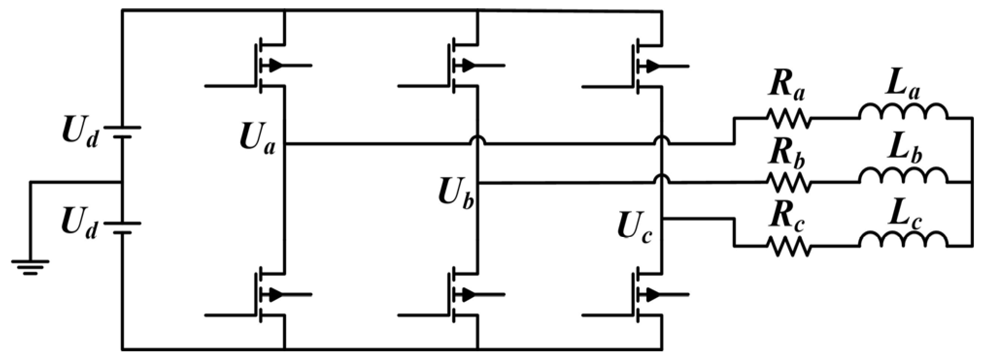
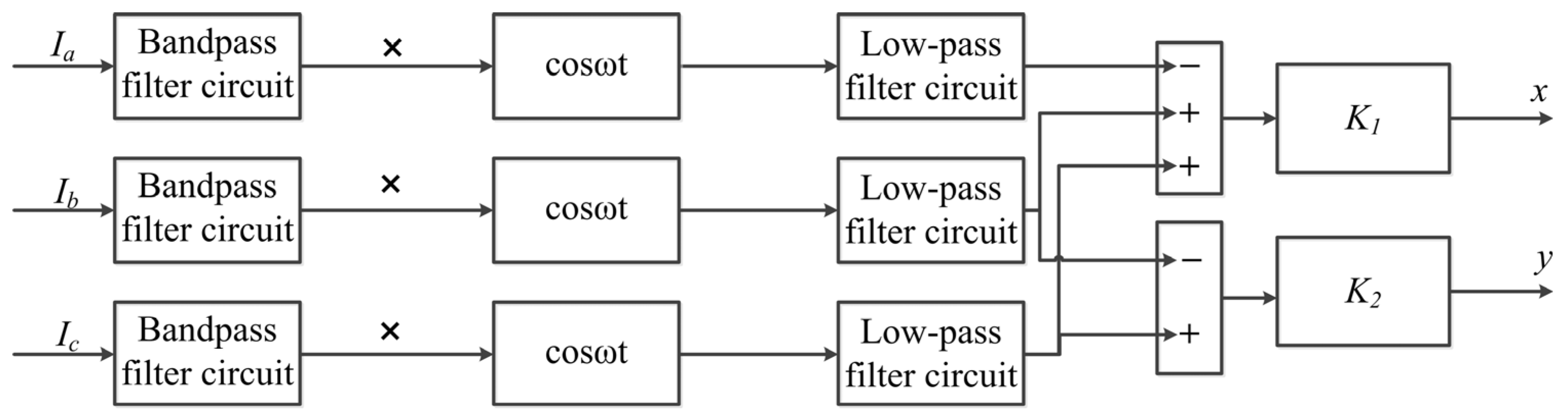
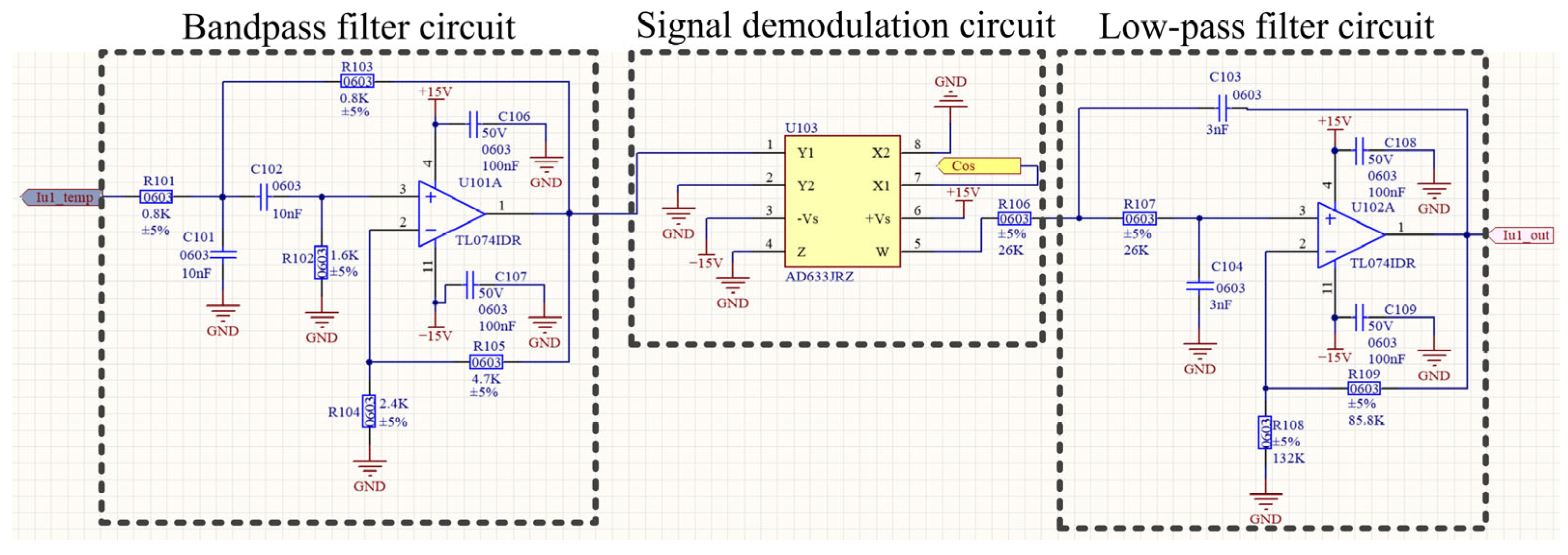
3.2. Displacement Signal Detection Circuit

The displacement self-sensing circuit adopted in this paper is shown in Figure 6. It consists of a band-pass filter circuit, a signal demodulation circuit, and a low-pass filter circuit. When the rotor in the flywheel battery system deviates from its equilibrium position, it causes changes in the three-phase current of the magnetic bearing. This displacement self-sensing circuit extracts the current signal to indirectly obtain the displacement of the rotor deviation, which is then fed back to the controller. After processing by the control algorithm, the output ensures the stable levitation of the rotor at the equilibrium position. The following sections will provide a detailed explanation of the three parts of the circuit.
(1)
Band-pass filter circuit
Since the ripple in the control coil current, which reflects the rotor air gap, is a high-frequency AC signal with frequency ωs, a band-pass filter circuit must be used to extract the rotor’s displacement signal while filtering out the DC component and AC signals above ωs. In this design, the center frequency is taken as fs = 20 kHz, the passband is 1 kHz, C101 = C102 = 10 nf, R101 = R103 = 0.8 kΩ, R102 = 1.6 kΩ, R104 = 2.4 kΩ, and R105 = 4.7 kΩ. Select the components as shown in Figure 6, and the transfer function of the band-pass filter circuit is calculated as follows:
Y ( s ) = 2.36 × 10 5 s 6.4 × 10 11 s 2 + 4 × 10 7 s + 1
(2)
Signal demodulation circuit
In this paper, the signal demodulation circuit multiplies the amplitude-modulated signal output from the band-pass filter circuit by the unit cosine signal cos(ωst) to obtain the demodulated electrical signal containing the rotor displacement information. In the displacement detection system, in order to improve the sensitivity of the detected signal, voltage-doubler detector circuits are mostly used. However, considering that components may generate unnecessary measurement errors as the temperature rises, this paper uses the four-quadrant analog multiplier chip AD633JRZ. It has high accuracy and good temperature stability, meeting the requirements of this circuit. Its transfer function is as follows:
W = ( X 1 X 2 ) ( Y 1 Y 2 ) 10 + Z
In the formula, X1, X2, Y1, Y2, and Z are all input voltages. X1 is connected to the output signal ibpf of the band-pass circuit, Y1 is connected to the unit cosine signal cos(ωs), and X2, Y2, and Z are all grounded. Then, we can obtain the following:
V O = i b p f cos ω s t 10
(3)
Low-pass filter circuit
The function of the low-pass filter circuit is to filter out the high-frequency components (2ωs) contained in the output waveform so as to obtain a useful signal that is consistent with the rotor displacement. In this paper, a second-order voltage-controlled voltage-source Butterworth low-pass filter is adopted. This filter has a high input impedance, a low output impedance, and the circuit performance is stable. In this design, the cut-off frequency of the low-pass filter circuit is designed to be 2 kHz, C103 = C104 = 10 nf, R106 = R107 = 26 kΩ, R108 = 132 kΩ, R109 = 85.8 kΩ. Select the components as shown in Figure 6, and the transfer function of the low-pass filter circuit is calculated as follows:
Y ( s ) = 2.7 × 10 8 s 2 + 641 s + 1.65 × 10 8

4. Design of a PID Controller Based on a Genetic BP Neural Network

In the existing research on the control system of the vehicle-mounted magnetic suspension flywheel battery, most of the studies considering the influence of road conditions only provide the optimal PID controller parameters corresponding to different road conditions, but do not explain how the controller performs real-time mode selection and outputs the optimal control parameters under different road conditions. In this paper, the coil current of the flywheel battery is converted into the position error by the sensorless technology for extensive training, so that the genetic BP neural network PID controller can accurately identify current complex road conditions according to the position error, thereby providing the optimal PID control parameters corresponding to the road conditions to perform accurate real-time stable control of the flywheel rotor. The principle of sensorless technology has been described in detail above, and the specific design scheme of the genetic BP neural network PID controller is introduced below.

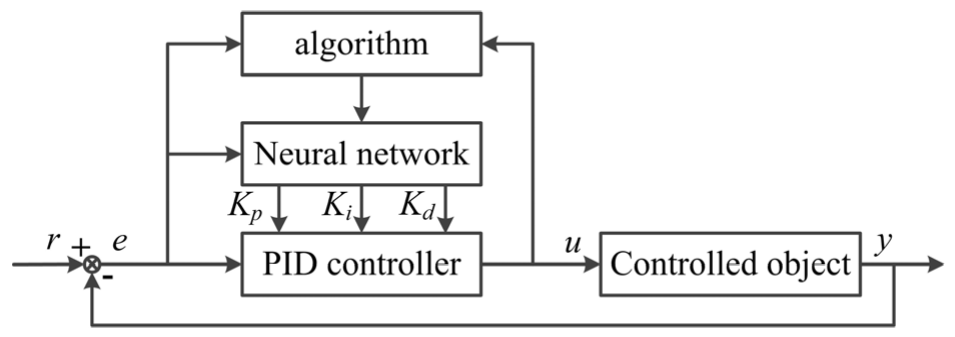
4.1. PID Control Based on a BP Neural Network

The error backpropagation neural network (BP network) is a type of multi-layer feedforward network with a hidden layer. It is one of the most widely used artificial neural network models [22]. It is composed of an input layer, a hidden layer, and an output layer. The mode of full connection between layers is mostly adopted; there is no interconnection between neurons in the same layer. If the number of input nodes in the network is N, and the number of output nodes is M, the neural network can be regarded as a mapping from N-dimensional Euclidean space to M-dimensional Euclidean space. This mapping is highly nonlinear. The BP model has a clear idea, rigorous structure, stable working state, and strong operability. It has been proven that a three-layer BP network with enough hidden layer nodes can approximate a nonlinear function with arbitrary precision. As shown in Figure 7. Many problems in the real world, such as pattern recognition, nonlinear mapping, complex system simulation, image processing, system identification, function fitting, optimization calculation, optimal prediction, adaptive control, etc., can be converted into this neural network for processing.
The learning process of the BP network mainly consists of the following parts:
  • The input mode is propagated forward. According to the teacher’s learning method, the input mode is propagated from the input layer through the middle layer to the output layer, and the corresponding actual output is calculated.
  • Output mode backpropagation. According to the principle of reducing the error between the expected output and the actual output, the connection weight is corrected layer by layer from the output layer through various intermediate layers and finally back to the input layer.
  • Cyclic memory training. The calculation process of model forward propagation and error backpropagation is repeated alternately. In order to minimize the output error of the network. For each set of training patterns input to the BP network, it is generally necessary to undergo hundreds or even tens of thousands of cycles of memory training to make the network remember this pattern.
  • Learning outcome discrimination. Determine whether the global error tends toward a minimum. After each cyclic memory training, the learning results should be judged. The purpose of judgment is mainly to check whether the output error has been small enough to allow. If the output error is small enough to allow, you can end the entire learning process, otherwise you need to cycle-train. As this error backpropagation training continues in a continuous cycle, the global error of the network tends toward the minimum, and the accuracy of the network’s response to the input pattern is also improved.
In order to obtain a good control effect of PID control in magnetic suspension flywheel battery control system, it is necessary to adjust the three control functions of proportional, integral, and differential to form the relationship of mutual cooperation and mutual restriction. This relationship is not a simple linear combination, but the best relationship can be found from the infinite nonlinear combinations. A neural network has strong nonlinear approximation abilities and learning abilities. Its structure and learning algorithm are simple and clear. Therefore, the indirect self-tuning control strategy is generated by combining the neural network algorithm with PID control. It can automatically adjust the parameters of the controller, realize PID control with the best combination, and make the system run under better performance. The BP neural network is used to optimize PID parameters. Through the learning process of the neural network itself, the P, I, and D parameters under the satisfactory control law can be found, namely Kp, Ki, and Kd. PID based on the BP neural network is shown in Figure 7.
The controller consists of two parts: (1) The classic PID controller. (2) According to the running state of the system, the parameters of the PID controller are adjusted in order to achieve the optimization of some performance indicators. The output state of the neurons in the output layer corresponds to the three adjustable parameters kp, ki, and kd of the PID controller. The steady state of the neural network corresponds to the PID controller parameters under some optimization control law. When kp, ki, and kd are regarded as adjustable coefficients dependent on the operating state of the system, the control formula of the classical incremental digital PID can be described as follows:
u ( k ) = f [ u ( k 1 ) , k p , k i , k d , e ( k ) , e ( k 1 ) , e ( k 2 ) ]
In the equation, f is a nonlinear function related to kp, ki, kd, u(k − 1), and y(k). A BP neural network can be used to find such an optimal control law through training and learning.
Let the BP neural network for PID control be a three-layer BP network; its structure is shown in Figure 8. There are M input nodes, Q hidden layer nodes, and three output nodes. Enter the number of nodes corresponding to the selected system running status. For example, the input and output of the system, at different times, should be normalized if necessary. The output nodes correspond to the three adjustable parameters, kp, ki, and kd, of the PID controller, respectively. Since kp, ki, and kd cannot be negative values, the activation function of neurons in the output layer is a non-negative Sigmoid function. The activation function of hidden layer neurons can be a Sigmoid function with positive and negative symmetry. The S-type function is chosen as the activation function for BP network neurons because it is continuously differentiable and more similar to the signal output form of biological neurons.
As can be seen from Figure 8, the input of BP neural network is as follows:
o j ( 1 ) = x k j = e ( k j ) o M ( 1 ) 1 , ( j = 0 , 1 , , M 1 )
In the equation, the number of input variables, M, depends on the complexity of the controlled system. The hidden layer input and output of the network are as follows:
n e t i ( 2 ) ( k ) = j = 0 M w i j ( 2 ) o j ( 1 ) ( k ) o i ( 2 ) ( k ) = f [ n e t i ( 2 ) ( k ) ] o i ( 2 ) ( k ) 1 , ( i = 0 , 1 , , Q 1 )
In the equation, wij(2) is the weighting coefficient of the hidden layer, wiM(2) is the threshold, and f is the activation function. The upper corner marks (1), (2), and (3) are the input layer, hidden layer, and output layer, respectively. Finally, the input and output of the output layer of the network are as follows:
n e t l ( 3 ) ( k ) = j = 0 Q w l i ( 3 ) o i ( 2 ) ( k ) o l ( 3 ) ( k ) = g [ n e t i ( 3 ) ( k ) ] o 0 ( 3 ) ( k ) = k p o 1 ( 3 ) ( k ) = k i o 2 ( 3 ) ( k ) = k d , ( l = 0 , 1 , 2 )
In the equation, wli(3) is the weighting coefficient of the hidden layer, wlQ(3) is the threshold, and g is the activation function. Take the performance indicator function as follows:
J 1 = 1 2 [ r ( k + 1 ) ( y + 1 ) ] 2 = 1 2 z 2 ( k + 1 )
The weighting coefficient of the network is modified according to the fastest descent method. That is, the negative gradient direction of the weighted coefficient is searched and adjusted according to J. Add an inertial term, which makes the search fast and globally minimal, then:
w l i ( 3 ) ( k + 1 ) = η J w l i ( 3 ) + α w l i ( 3 ) k
In the equation, η is the learning rate and α is the inertia coefficient.
J w l i ( 3 ) = J y ( k + 1 ) y ( k + 1 ) u ( k ) u ( k ) o l ( 3 ) k o l ( 3 ) k n e t l ( 3 ) k n e t l ( 3 ) k w l i ( 3 )
Since ∂y(k + 1)/∂u(k) is unknown, it is approximated by the symbolic function sgn(∂y(k + 1)/∂u(k)). The effect of the resulting computational inaccuracy can be compensated by adjusting the learning rate η. It can be concluded that
u ( k ) o 0 ( 3 ) ( k ) = e ( k ) e ( k 1 ) u ( k ) o 1 ( 3 ) ( k ) = e ( k ) u ( k ) o 2 ( 3 ) ( k ) = e ( k ) 2 e ( k 1 ) + e ( k 2 )
Therefore, the calculation equation of weighting coefficient of output layer of the BP neural network can be obtained as follows:
w l i ( 3 ) ( k + 1 ) = η δ l ( 3 ) o i ( 2 ) ( k ) + α w l i ( 3 ) ( k ) δ l ( 3 ) = e ( k + 1 ) sgn ( y ( k + 1 ) u ( k ) ) × u ( k ) o l ( 3 ) ( k ) g [ n e t l ( 3 ) ( k ) ] , ( l = 0 , 1 , 2 )
According to the above calculation method, the calculation equation of the weighting coefficient of the hidden layer can be obtained as follows:
w l i ( 2 ) ( k + 1 ) = η δ i ( 2 ) o j ( 1 ) ( k ) + α w i j ( 2 ) ( k ) δ l ( 2 ) = f [ n e t i ( 2 ) ( k ) ] l = 0 2 δ l ( 3 ) w l i ( 3 ) , ( i = 0 , 1 , , Q 1 )
In the equation, g′ = g(x)∙g [1 − g(x)] and f′ = [1 − f2(x)]/2.
The PID control algorithm based on the BP neural network can be summarized as follows:
  • The structure of the BP neural network is selected in advance. That is, the number of nodes in the input layer, M, and the number of nodes in the hidden layer, Q, are selected, and the initial values of the weighting coefficients of each layer, wij(2)(0) and wli(3)(0), are given. Select the learning rate η and the inertia coefficient, α; k = 1.
  • Sample r(k) and y(k); calculate e(k) = z(k) = r(k) − y(k).
  • For r(i), y(i), u(i − 1), (i =k, k − 1,..., kp) for normalization processing, as the input of the neural network.
  • The input and output of neurons in each layer of the neural network are calculated forward according to Equations (18)~(20). The output of the neural network’s output layer is the three adjustable parameters of the PID controller: kp(k), ki(k), and kd(k).
  • Calculate the control output u(k) of the PID controller; participate in the control and calculation. Calculate the weighted coefficient of the corrected output layer. Calculate the weighted coefficient of the corrected hidden layer. Set k = k + 1; return to 1.
A large number of simulation results show that the application of neural networks to improve the conventional PID controller can improve the robustness and dynamic characteristics of the system and effectively improve the control effect of the system.

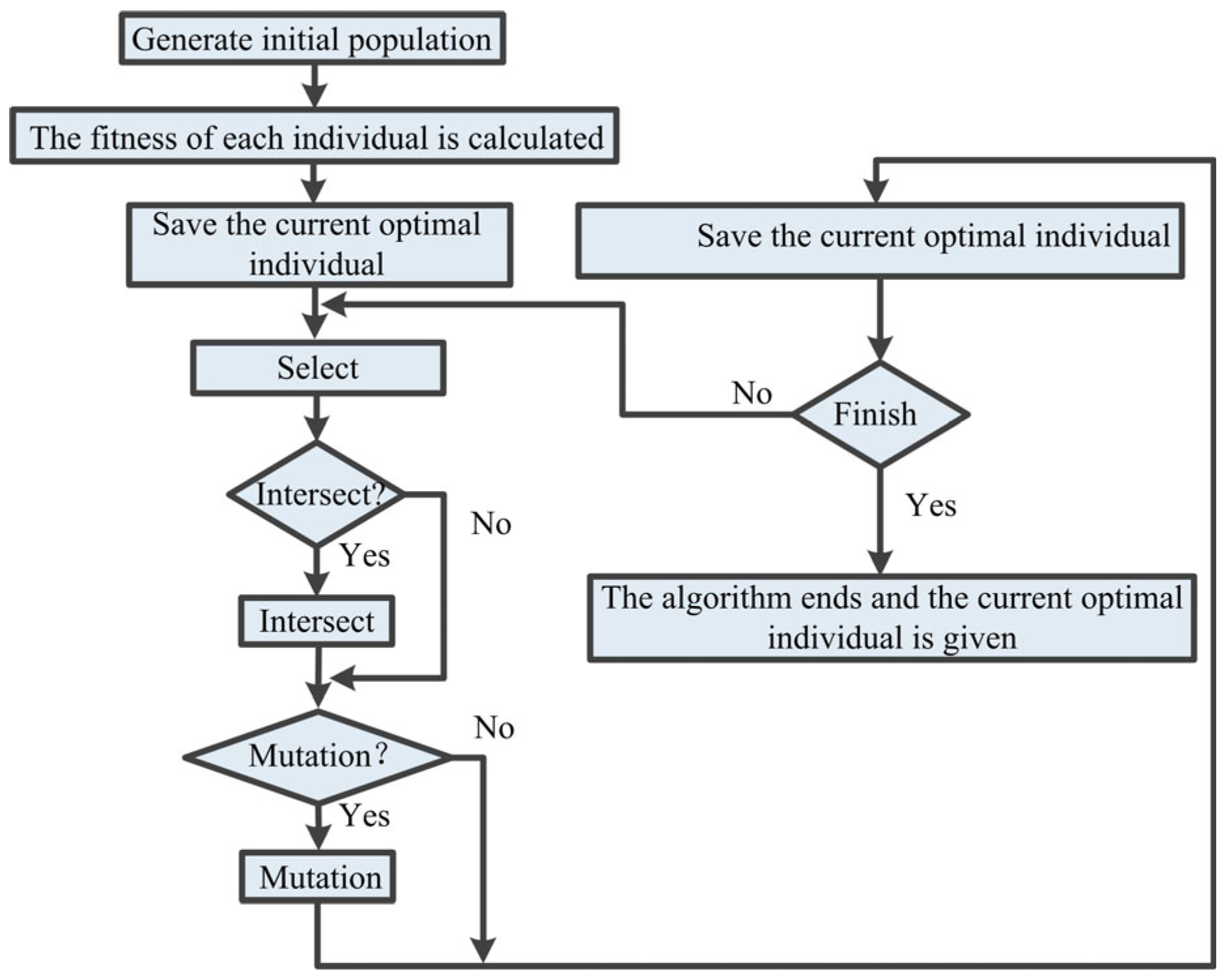
4.2. The Combination of Genetic Algorithms and Artificial Neural Networks

The basic principle of this combination method is a fixed network structure, and a genetic algorithm is used to train network connection weights. Because of the disadvantages of BP training, such as the possibility of falling into a local minimum, the genetic algorithm can be used to replace BP as the learning algorithm of the forward network. The genetic algorithm, as a learning algorithm, should mainly solve the coding scheme problem; that is, the mutual mapping between network weights and chromosomes. The algorithm steps for optimizing neural network connection weights with the genetic algorithm are as follows:
  • Select the network structure and learning rules. A set of connection weights is randomly generated, and each connection weight is encoded by some coding scheme. The link weights in the network are arranged at one time to form a code chain. Each code chain represents a connection weight distribution state of the network, and a group of code chains represents a group of neural networks with different connection weights.
  • The error function of the neural network under each corresponding code chain is calculated, and the fitness function of genetic algorithm is given. The smaller the error, the higher the fitness value.
  • Several individuals with the largest fitness function were selected to form the paternal parent.
  • Crossover, mutation, and other genetic operators are used to process the current generation population and produce a new generation population.
  • Repeat the above steps so that the weight distribution continues to evolve until the training goal is reached.
The structure of a neural network includes the topology of the network and the node transfer function. It is always expected that a simple network structure can realize the required signal-processing function and achieve the highest performance index as far as possible. However, the selection and design of neural network structures have not found an effective and reasonable method. The genetic algorithm can be used to design neural networks according to certain performance evaluation criteria, such as learning speed, generalization ability, or structural complexity, in order to search for the best structure in the structural space to meet the requirements of the problem. One of the key problems in designing a neural network using a genetic algorithm is how to choose the coding scheme. The algorithm steps for optimizing neural network structure with a genetic algorithm are as follows:
  • A neural network that randomly generates several different structures. Each structure is coded, each code chain corresponds to a network structure, and N code chains constitute a population.
  • Each network is trained separately with a variety of initial connection weights.
  • Calculate the error function of the neural network under each corresponding code chain and use the error function or other strategies to determine the fitness function of each individual.
  • Several individuals with the largest fitness function values were selected to form the paternal parent.
  • Crossover, mutation, and other performance operators are used to deal with the current generation of groups and produce a new generation of groups.
  • Repeat the above steps until an individual in the group meets the requirements.
In the neural network training problems discussed above, the learning rules are set in advance and may not be reasonable. Genetic algorithms can be used to design the learning rules of artificial neural networks. By adapting it to the requirements of the environment through evolution, new rules can also be discovered. Generally speaking, the evolution of learning rules includes two aspects: the evolution of learning parameters and the evolution of learning rules. In order to achieve this kind of evolution, the key question is how to encode the learning rules. The algorithms for optimizing the learning rules of neural networks with the help of genetic algorithms are as follows:
  • Several individuals are generated, each individual corresponds to a learning rule, and each learning rule is encoded by some coding scheme.
  • Form a training set, where each element corresponds to a neural network. The structure and initial connection weights of each neural network are selected or randomly generated, and then the elements of the training set are trained separately with each learning rule.
  • Calculate the fitness of each learning rule.
  • Several individuals with the largest fitness function values were selected to form the paternal parent.
  • Crossover, mutation, and other genetic operators are used to process the current generation population and produce a new generation population.
  • Repeat the above steps until an individual in the group meets the requirements.
Above, we discuss the combination principle of genetic algorithms to optimize the connection weight, structure, and learning rules of neural networks. In addition, the combination of genetic algorithms and artificial neural networks has various other forms. For example, genetic algorithms are used for feature extraction to optimize the input signal of neural networks. At this time, the genetic algorithm completes the pre-processing function of the input data of the neural network. The success of feature extraction plays a key role in the result of pattern classification. Genetic algorithms can be used to select the scale factors of the parameters and features of the data set, reduce the intra-class difference between the data, expand the inter-class difference, and improve the classification performance of artificial neural networks.

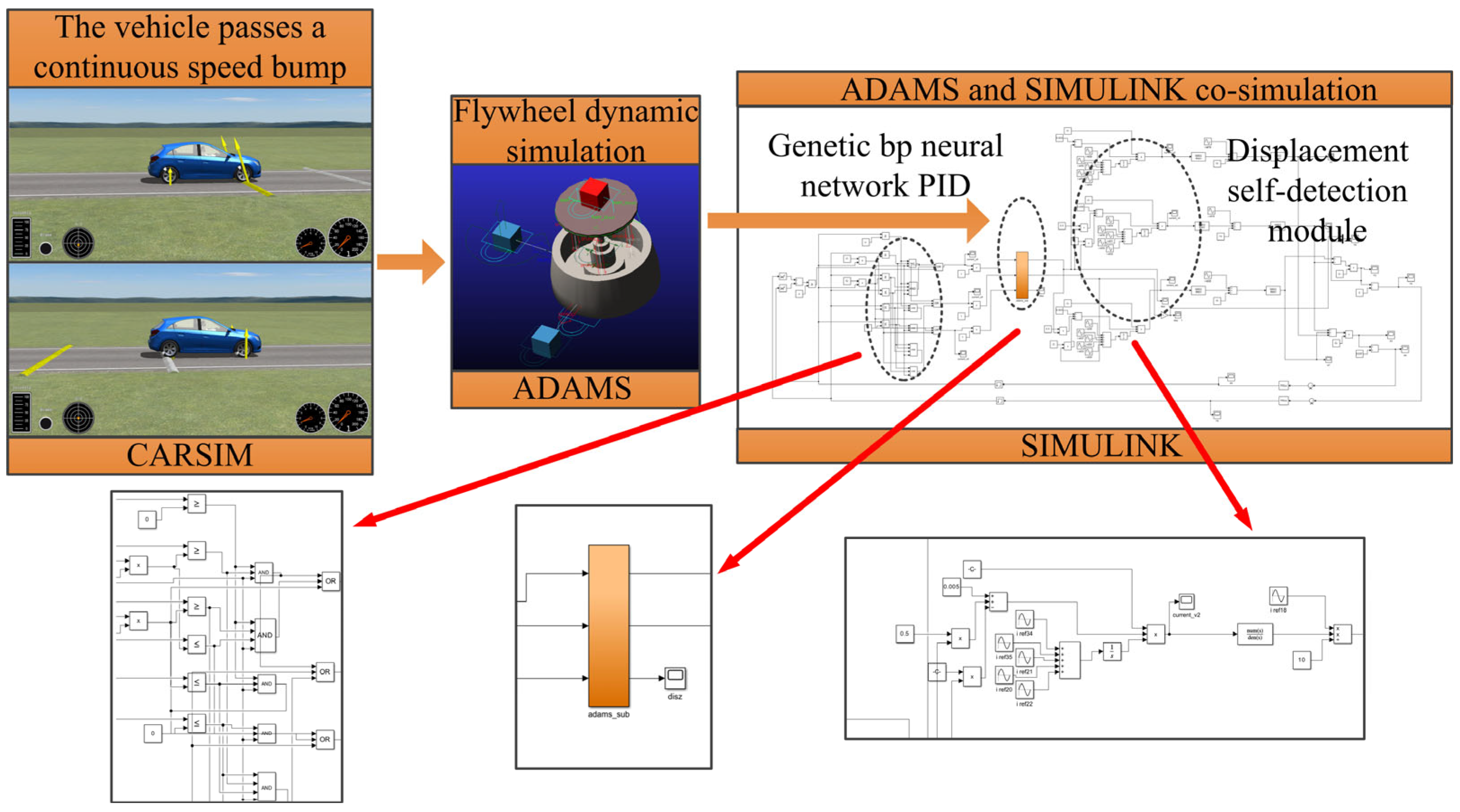
4.3. Application of PID Controller Based on Genetic BP Neural Networks in Sensorless Technology of Flywheel Batteries

Since the setting of the initial state of the network is an important problem in the application of neural networks, genetic algorithms are used to optimize the initial weights of each neural network. Here, the genetic algorithm is an efficient optimization method that does not require any initial information and can seek a global optimal solution. In this paper, the genetic algorithm is selected for parameter optimization. The initial weight of the BP neural network is sent to the neural network to learn the optimal P, I, and D parameter values. The flow chart of the genetic algorithm designed in this paper to optimize the connection weights of BP neural networks is shown in Figure 9.
In order to reflect the requirements of the performance indicators of the neural network controller, the fitness function is designed as follows:
J = α σ max σ σ max + β t max t s t max t s min + γ e max e s e max
In the equation, σ, st, and es are the overshoot, adjustment time and steady-state error of the control system, respectively. α, β, and γ are the weighted values of each performance index, indicating the relative importance of each performance index, with α + β + γ = 1. When implementing genetic algorithm optimization, the population size is set to 50. The 49 individuals in the initial population were randomly generated by a computer. The upper and lower limits of each individual are set according to the upper and lower limits of the connection weights of the trained BP neural network. The 50th individual is the connection weight of the trained BP neural network. The 50 initial individuals were applied to the flywheel battery. In this paper, the selection mechanism of the genetic algorithm adopts the betting wheel method; that is, the probability of each individual being selected is proportional to its fitness value. The advantage of this selection mechanism is that the whole evolution process is always in the direction of optimization and finally converges to the global optimal value. Both the crossover operation and the mutation operation are carried out randomly: a random number x between 0 and 1 is generated. If x < Pc (Pm), a crossover or mutation operation is performed. The individual performing the crossover operation is the connection weight of two adjacent groups of neural networks, and the crossover mode is shown in Equation (28):
s o n ( i ) = a × d a d ( i ) + ( 1 r ) × d a d ( i + 1 ) s o n ( i + 1 ) = a × d a d ( i + 1 ) + ( 1 r ) × d a d ( i ) , ( i = 1 , 2 , , 50 )
In order to increase the diversity of variant individuals, two variants were designed. If b < 0.5, then proceed according to Equation (29); otherwise proceed according to Equation (30):
s o n ( i ) = s o n ( i ) + c × ( max s o n ( i ) ) , ( i = 1 , 2 , , 50 )
s o n ( i ) = s o n ( i ) c × ( s o n ( i ) min ) , ( i = 1 , 2 , , 50 )
where dad(i) and son(i) respectively represent the i-th individual in the generation that performs the crossover or mutation operation; that is, the connection weight of the Group i neural network. a, b, and c are randomly generated numbers between 0 and 1. In order to ensure the algorithm convergence and speed up the algorithm convergence, the optimal individual retention strategy is adopted; that is, the optimal individual in the k generation is selected and compared with the optimal individual in the previous generation. The superior is placed in the population as the optimal individual, and it does not participate in any genetic manipulation. When the genetic search converges, the fitness values of most individuals in the solution population are located near a certain value. This paper takes this as one of the termination conditions of the algorithm and sets the maximum genetic algebra. In the maximum genetic algebra, the algorithm is terminated even if no quasi-optimal solution is found.

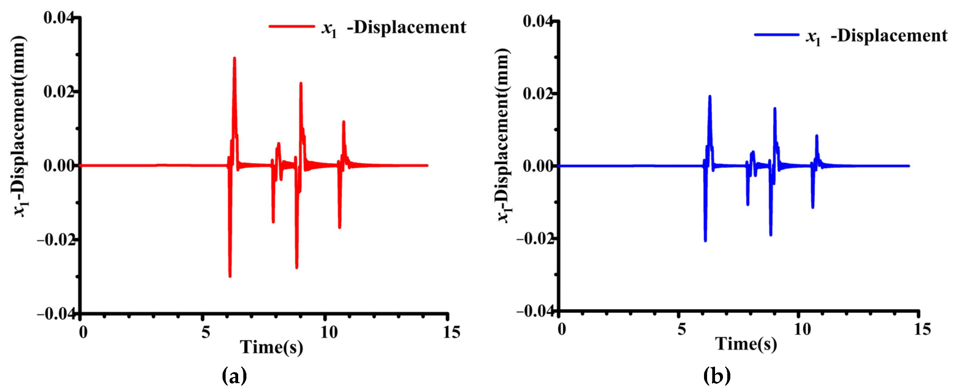
4.4. Simulation Results

This paper presents a flywheel battery control system based on sensorless technology to deal with the problem of sensor loosening caused by shell vibration. There are many road conditions that easily cause vibration of the flywheel battery housing, of which the most influential are bumpy road conditions. The most common bumpy road condition is the road condition of the vehicle over the speed bump; thus, the following takes the vehicle over the speed bump as an example to simulate. The control effect of the sensorless control system is not perfect because of its low precision. Thus, the genetic BP neural network is introduced to improve the PID controller of the control system. The control coil current of the flywheel battery was sampled and used as a sample for training. Let the control system identify the current road condition according to the current flow. So as to deal with the bumpy road conditions, choose the most appropriate PID control parameters according to the current road condition for control. The specific control block diagram is shown in Figure 10.
In order to obtain the actual external disturbance of vehicle-mounted flywheel battery under the coupling excitation of vehicle and road conditions in actual bumpy road conditions. Therefore, the most classic continuous speed strip road conditions were selected in the vehicle simulation software CARSIM2020.0 for simulation. Set the speed at which the speed bump is 10 km/h, with the distance between the two speed bumps set at 4.5 m and the height of the speed bump set at 7 cm. The simulation vehicle selected the most common Class A vehicle in daily life, with a body length of 4.3 m. The specific simulation data is shown in Table 1. Through the CARSIM vehicle simulation software, the longitudinal acceleration, lateral acceleration, and vertical acceleration data of vehicles under bumpy road conditions can be obtained. After these acceleration data are obtained, the acceleration data of the corresponding direction of the body are respectively imported into the upward drive of the flywheel dynamics model in the dynamics simulation software ADAMS. The dynamic response of the flywheel battery rotor is obtained through simulation by setting the translation drive, and the dynamic performance of the flywheel rotor directly affected by the vehicle is obtained. When the flywheel rotor is disturbed by the coupling excitation of vehicle-speed belt road conditions, the rotor will shift in the equilibrium position. The real-time current signal after disturbance can be sampled by the displacement self-detection module. The position deviation signal is obtained by converting the current signal into the displacement signal and comparing it with the equilibrium position reference signal. The position error signal is sent to the PID controller optimized by the genetic BP neural network for processing. This part of the simulation adopts ADAMS and SIMULINK co-simulation. The entire simulation process is shown in Figure 11.
The rotor offset waveform obtained by simulation is shown in Figure 12. The front and rear wheels of the simulated vehicle pass over two speed bumps, respectively, and the body will be disturbed four times in total. The disturbance is transmitted by the vehicle to the flywheel battery. The flywheel rotor will deviate from the equilibrium position under the disturbance, resulting in a deviation. The smaller the offset, the better the performance of the control system. The red waveform is the rotor radial offset of the flywheel battery under the control of a conventional PID controller. The maximum offset is about 0.03 mm. The blue waveform is the rotor radial offset of the flywheel battery under the control of the genetic BP neural network PID controller. The maximum offset is about 0.02 mm. As a result, the controller’s performance is improved by about 33%. It can effectively solve the shortcomings of low control accuracy in the sensorless control system.
Although this paper adopts two classical control technologies, it does not simply superimpose the two technologies but conducts a comprehensive analysis and consideration according to the particularity of the controlled object. Based on the above principle analysis and simulation results, a summary is provided here. The innovations of this paper are as follows:
(1)
Most of the existing research on sensorless technologies for magnetic suspension flywheel batteries does not take into account the influencing factors of the application scenarios. Due to the particularity of the application scenario of vehicle-mounted flywheel batteries, the sensorless control strategy in this paper considers the adverse impacts of the important factor of complex and changeable road conditions on the rotor suspension stability of vehicle-mounted flywheel batteries and the performance of the control system and proposes an optimization scheme.
(2)
In existing research on the control systems of vehicle-mounted magnetic suspension flywheel batteries, among most of the studies that consider the influence of road conditions, only the optimal PID controller parameters corresponding to different road conditions are provided, but there is no explanation of how the controller conducts real-time mode selection and outputs the optimal control parameters under different road conditions.
(3)
In research on the control systems of vehicle-mounted magnetic suspension flywheel batteries, when a small number of studies use neural network algorithms to optimize the controller, they only consider simple road conditions, such as acceleration, deceleration, turning, going uphill, etc. However, the driving environment for vehicles in real life is more complex. This paper takes into account more complex, continuous interference road conditions. Through the joint simulation of the dynamics simulation software ADAMS and MATLAB, a database of optimal PID control parameters for complex road conditions has been established. Through sensorless technology, the current of the flywheel battery is converted into an offset for a large number of training sessions, enabling the genetic BP neural network PID controller to accurately identify the current complex road conditions according to the offset and provide the best PID control parameters corresponding to the road conditions to precisely and stably control the flywheel rotor in real time.

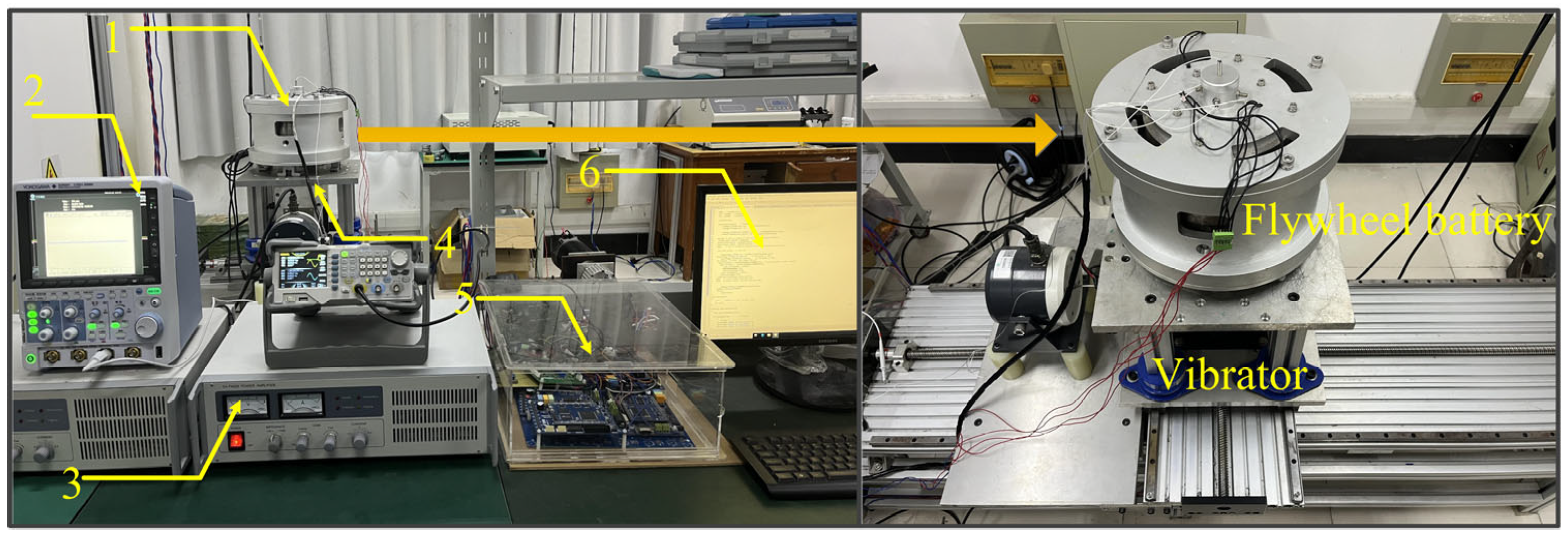
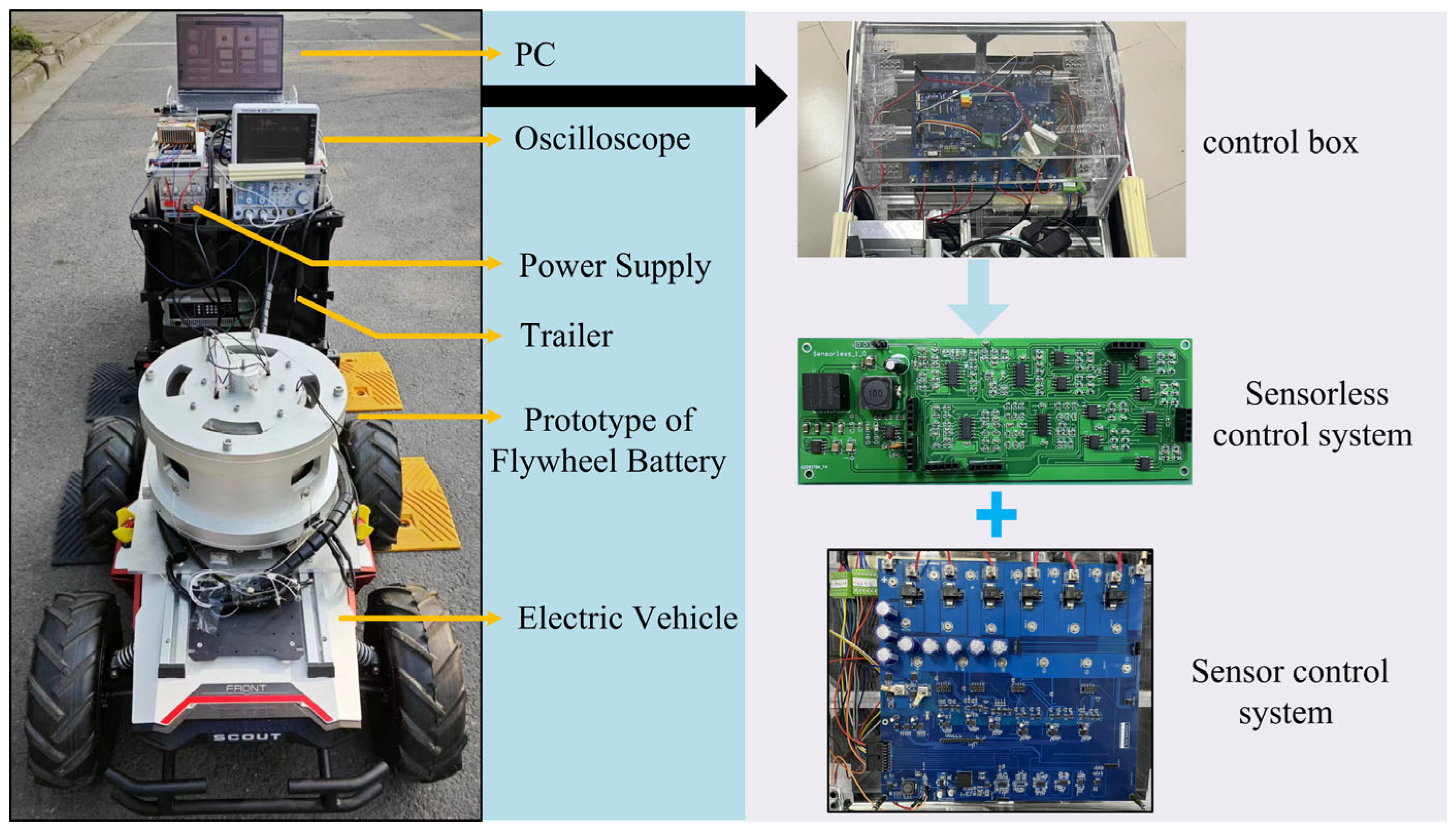
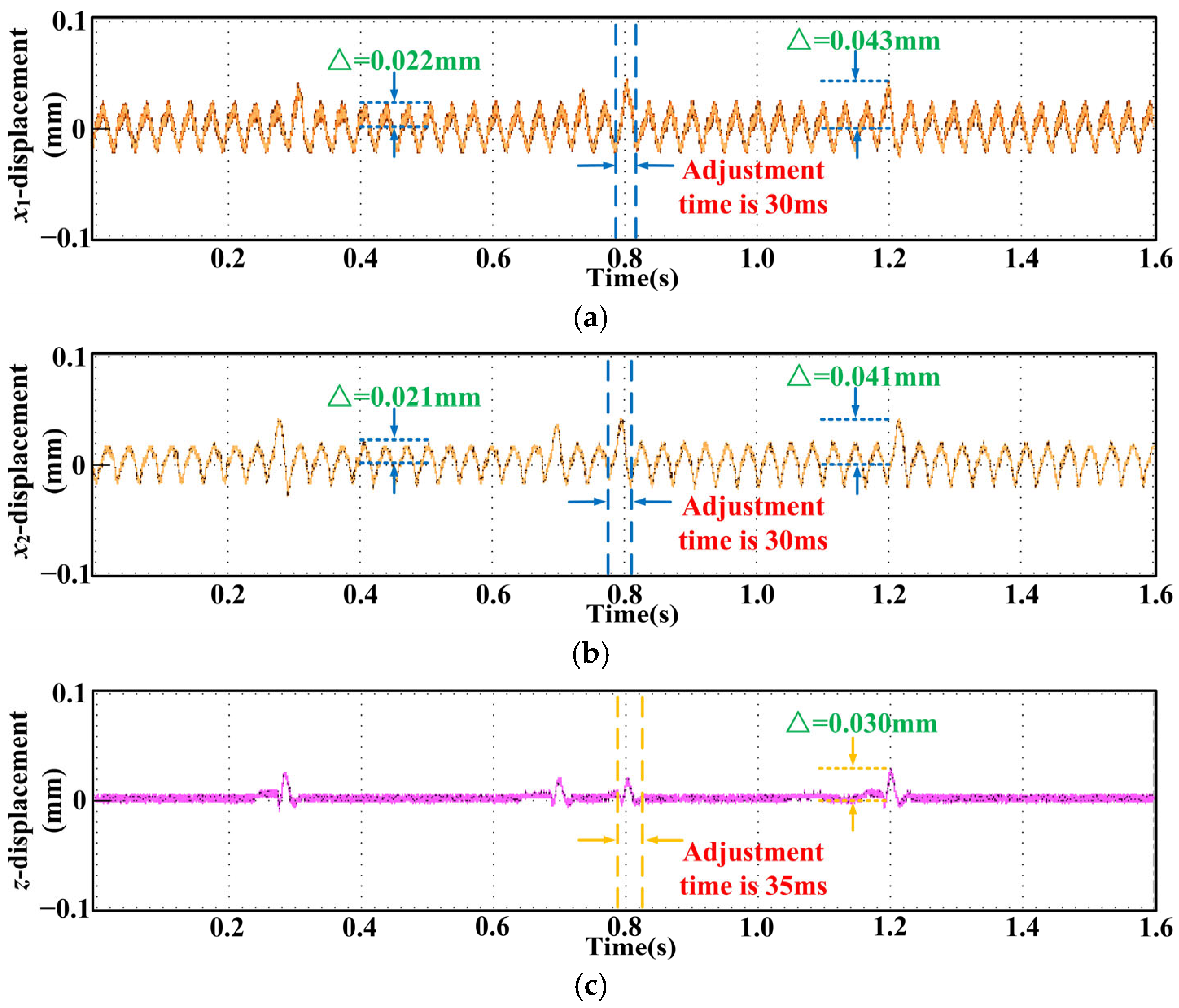
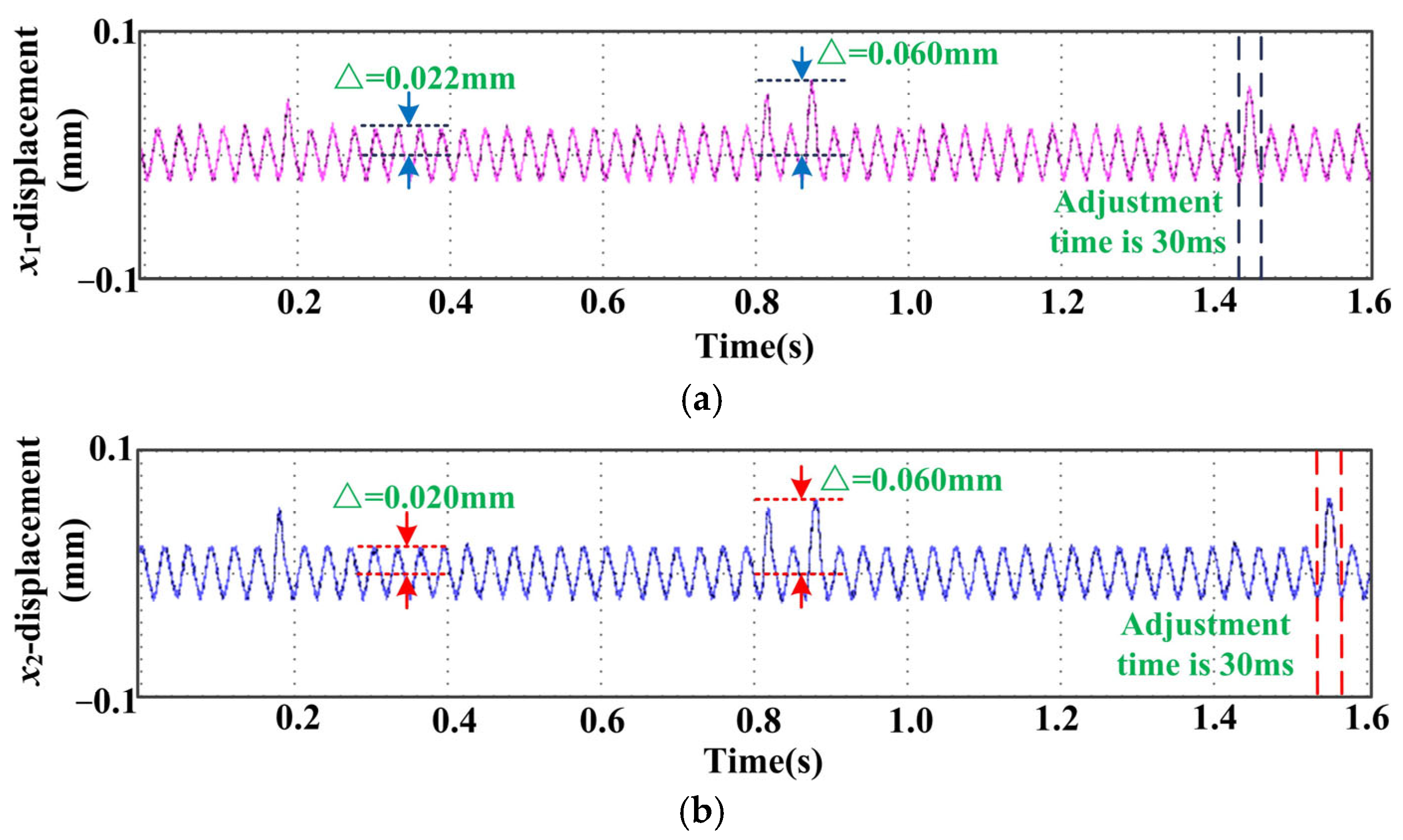
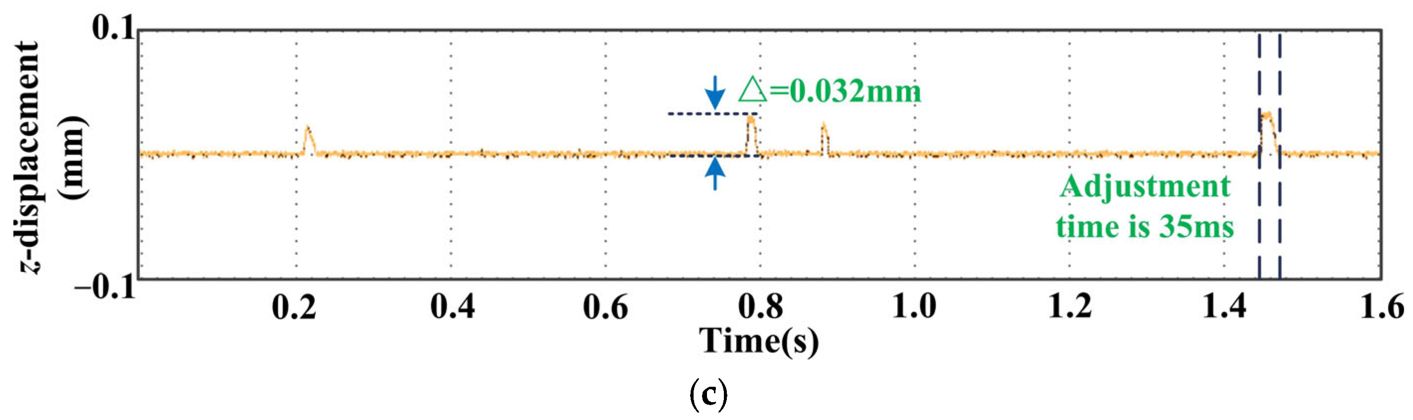
5. Experiments and Results

In order to verify the performance of the genetic BP neural network sensorless control system proposed in this paper, the flywheel battery system is designed as close to the real application scenario as possible. The following experiments are all based on the mobile vehicle-mounted flywheel battery experimental platform shown in Figure 13. The experimental platform includes the body of a 5-DOF flywheel battery, an electric experimental car, a flywheel battery control system, an oscilloscope, and an upper computer. The vehicle structural parameters of the experimental vehicle are shown in Table 2. The mobile vehicle-mounted flywheel battery is fixed to the electric experimental car. It can not only simulate the impact of the vehicle itself on the flywheel battery system but also simulate the interference of different vehicle working conditions and road conditions on the flywheel battery system.
When the vehicle encounters continuous disturbances, both the body and the vehicle-mounted flywheel battery system undergo significant vibrations. This vibration can cause the sensor installed in the flywheel housing to loosen, leading to inaccurate feedback data. Consequently, the precision of the flywheel battery control system is substantially compromised. The application of sensorless technology in vehicle-mounted flywheel control systems can avoid such problems very well. However, in terms of control effect, it is necessary to ensure that the non-sensing control system is as accurate and reliable as the sensing control system. Based on this purpose, the continuous interference comparison experiment of the vehicle-mounted flywheel battery system is carried out. The vehicle used in the simulation of this study is a household vehicle that runs in daily life, and its suspension system is more stable. Therefore, under the road conditions of continuous speed bumps, the disturbance of the body vibration to the flywheel rotor is relatively small. The vehicle used in the experiment is a small experimental vehicle, and its suspension system is slightly less stable than that of household vehicles, so the disturbance of the body vibration to the flywheel is slightly larger. If the control system can be controlled stably in the case of large disturbances, then the disturbance can still be controlled stably when reduced.
Taking the most common continuous speed bump road conditions as an example, the experimental car conducted three consecutive speed bump experiments. The first experimental car was equipped with a sensor control system based on a traditional PID controller. The second experimental car was equipped with a sensorless control system based on a traditional PID controller. The third experimental car was equipped with a sensorless control system based on a genetic BP neural network PID controller. An oscilloscope is used to compare the flywheel rotor offset, and then the two control effects were compared. First, set the experimental conditions: the mobile vehicle-mounted flywheel battery test platform passes through a continuous speed bump with a height of 7 cm at a speed of 5 m/s. The driving direction of the vehicle is the x-direction of the displacement coordinate axis of the vehicle-mounted flywheel rotor. The length of the experimental car is 1.2 m. When the experimental car overpasses the speed reduction belts 1 and 2, there are two vibrations of the front wheel and the rear wheel, respectively. The two speed bumps have four vibrations. Therefore, in order to facilitate the observation of experimental waveforms, the interval between the two speed belts is set at 1.5 m. The process of the experimental car passing the continuous speed bump is shown in Figure 14.
The waveform of flywheel rotor displacement from the first continuous speed belt road condition experiment is shown in Figure 15. The control parameters of the traditional PID controller are shown in Table 3. Since the vehicle is only traveling in the x direction, the flywheel rotor will only have a large offset in the x and z directions when the vehicle hits the speed bump. As shown in Figure 15. From the perspective of radial, the rotor produces four large offsets in the direction of x1. The maximum peak is about 0.043 mm, which is quickly adjusted to about 0.022 mm. From the perspective of torsion, the rotor also produces four large offsets in the x2 direction. The maximum peak is also about 0.041 mm, which is quickly adjusted to about 0.021 mm. From the perspective of axial, the rotor produces four large offsets in the same z direction. The maximum peak value is about 0.030 mm, and it quickly returns to stability. In terms of transient response, the peak time of the three response curves is 0.3 s, the adjustment time of the radial response curve and the torsional response curve is 30 ms, and the adjustment time of the axial response curve is 35 ms.
As shown in Figure 16. From the perspective of radial, the rotor produces four large offsets in the direction of x1. The maximum peak is about 0.060 mm, which is quickly adjusted to about 0.022 mm. From the perspective of torsion, the rotor also produces four large offsets in the x2 direction. The maximum peak is also about 0.060 mm, which is quickly adjusted to about 0.020 mm. From the perspective of axial, the rotor produces four large offsets in the same z direction. The maximum peak value is about 0.042 mm, and it quickly returns to stability. In terms of transient response, the peak time of the three response curves is 0.2 s, the adjustment time of the radial response curve and the torsional response curve is 30 ms, and the adjustment time of the axial response curve is 35 ms.
The flywheel rotor displacement waveform of the third continuous speed belt road condition experiment is shown in Figure 17. The control parameters of the genetic BP neural network PID controller are shown in Table 4. From the perspective of radial, the maximum deflection of the rotor in the x1 direction is reduced from 0.042 mm to about 0.015 mm. From the perspective of torsion, the maximum offset of the rotor in the x2 direction is reduced from 0.041 mm to about 0.014 mm. From the perspective of axial, the maximum offset of the rotor in the z direction is controlled from 0.032 mm to stability. In terms of transient response, the peak time of the three response curves is 0.2 s, the adjustment time of the radial response curve is 30 ms, the adjustment time of the torsional response curve is 28 ms, and the adjustment time of the axial response curve is 35 ms.
By comparing the three sets of waveforms above, the following conclusions can be drawn: In the first experiment, the experimental waveform amplitude of the sensorless control system based on the traditional PID controller is the smallest; that is, the flywheel rotor is the most stable when subjected to continuous impact. In the second experiment, the experimental waveform amplitude of the sensorless control system based on the traditional PID controller is the largest; that is, the flywheel rotor has the worst stability. Therefore, although the sensorless control system can save costs, the control performance still needs to be improved. In the third experiment, the genetic BP neural network PID controller is used to optimize the sensorless control system. Compared with the traditional sensorless control system, the amplitude of the experimental waveform is greatly reduced; that is, the flywheel rotor is more stable. The maximum offset of the flywheel rotor is smaller than that of the conventional PID controller. The average is about 0.015 m. When the flywheel rotor stabilizes, the offset of the flywheel rotor is about 0.005 mm smaller than that of the traditional PID controller. It can be seen that although the cost of the sensorless control system is lower, the control performance is poor. The PID controller using genetic BP neural networks can improve the overall control performance of the flywheel battery sensorless control system. The improvement rate is about 25%.

6. Conclusions

In this paper, a BP neural network PID control method based on a genetic algorithm is proposed to solve the problems of sensor precision decrease, high cost, and complex installation in the vehicle maglev flywheel battery control system under complex road conditions. In this method, the current flow of the magnetic bearing coil is sampled by the hardware circuit and converted into displacement. Combining a genetic algorithm to optimize the initial weights and structural parameters of the neural network, the traditional BP neural network can overcome the defects of slow convergence speed and its tendency to fall into local minima. Experimental results show that this method can output the optimal control parameters in real time under complex road conditions. The feedback error is significantly reduced, and the precision and dynamic performance of the sensorless control system are improved. In addition, the introduction of the genetic algorithm further improves the search efficiency and learning accuracy of the neural network, making the control system more adaptive and robust. In terms of innovation, this article has the following three aspects of innovation: (1) The theory of this article is innovative. It combines sensorless technology with the genetic BP neural network PID controller and also takes into account the characteristics of this study (the analysis of road condition interference factors), which improves the benefit ratio of the vehicle-mounted flywheel battery control system. (2) The technical implementation of this article is innovative. According to the particularity of the controlled object, the hardware circuit design of the displacement self-sensing circuit for the vehicle-mounted flywheel battery has been completed, and detailed design ideas and component parameters are provided. (3) The experimental methods of this article are innovative. This article has designed a mobile vehicle-mounted flywheel battery experimental platform, which ensures the accuracy and reliability of the experimental data.
However, there are still some limitations in this study. In the process of converting the current into displacement, the noise and nonlinear characteristics of the hardware circuit may introduce additional errors and affect the control accuracy. Future research may explore more accurate signal acquisition and processing techniques to further reduce errors in the data conversion process.

Author Contributions

Project administration, W.Z.; writing—original draft, W.Z. and F.G.; conceptualization, W.Z.; methodology, F.G.; software, F.G.; validation, F.G. All authors have read and agreed to the published version of the manuscript.

Funding

This work is supported in part by the National Natural Science Foundation of China under Grant 52077099, and in part by the project funded by the Priority Academic Program Development of Jiangsu Higher Education Institutions.

Data Availability Statement

The original contributions presented in the study are included in the article, and further inquiries can be directed to the corresponding author.

Conflicts of Interest

The authors declare no conflicts of interest.

References

  1. Li, X.; Anvari, B.; Palazzolo, A.; Wang, Z.; Toliyat, H. A utility-scale flywheel energy storage system with a shaftless, hubless, high-strength steel rotor. IEEE Trans. Ind. Electron. 2018, 65, 6667–6675. [Google Scholar]
  2. Rath, M.; Schweighofer, B.; Wegleiter, H. Influence of position on optoelectronic strain measurement systems for flywheels. IEEE Sensors Letters 2023, 7, 6005404. [Google Scholar]
  3. Bianchini, C.; Torreggiani, A.; David, D.; Bellini, A. Design of motor/generator for flywheel batteries. IEEE Trans. Ind. Electron. 2021, 68, 9675–9684. [Google Scholar]
  4. Ershad, N.F.; Mehrjardi, R.T.; Ehsani, M. Efficient flywheel-based all-wheel-drive electric powertrain. IEEE Trans. Ind. Electron. 2021, 68, 5661–5671. [Google Scholar]
  5. Kienast, J.; Bernet, S.; Sturm, G. Operation, design, and losses of the modular multilevel matrix converter in a flywheel energy storage system. IEEE Open J. Ind. Appl. 2023, 4, 336–345. [Google Scholar]
  6. Yan, H.; Wang, W.; Xu, Y.; Zou, J. Position sensorless control for PMSM drives with single current sensor. IEEE Trans. Ind. Electron. 2023, 70, 178–188. [Google Scholar]
  7. Chen, Y.; Du, L.; Sun, Q.; Bai, J.; Li, H.; Shi, Y. Self-calibration method of displacement sensor in AMB-rotor system based on magnetic bearing current control. IEEE Trans. Ind. Electron. 2024, 71, 5148–5156. [Google Scholar]
  8. Zhu, H.; Liu, T. Rotor displacement self-sensing modeling of six-pole radial hybrid magnetic bearing using improved particle Swarm optimization support vector machine. IEEE Trans. Power Electron. 2020, 35, 12296–12306. [Google Scholar]
  9. Yu, J.; Zhu, C. A multifrequency disturbances identification and suppression method for the self-sensing AMB rotor system. IEEE Trans. Ind. Electron. 2018, 65, 6382–6392. [Google Scholar]
  10. Peng, C.; Zheng, S.; Huang, Z.; Zhou, X. Complete synchronous vibration suppression for a variable-speed magnetically suspended flywheel using phase lead compensation. IEEE Trans. Ind. Electron. 2018, 65, 5837–5846. [Google Scholar]
  11. Yang, J.; Li, Q.; Huang, S.; Ye, C.; Liu, P.; Ma, B.; Wang, L. Design and Analysis of a Novel Permanent Magnet Homopolar Inductor Machine with Mechanical Flux Modulator for Flywheel Energy Storage System. IEEE Trans. Ind. Electron. 2022, 69, 7744–7755. [Google Scholar]
  12. Yang, J.; Liu, P.; Ye, C.; Wang, L.; Zhang, X.; Huang, S. Multidisciplinary design of high-speed solid rotor homopolar inductor machine for flywheel energy storage system. IEEE Trans. Transp. Electrif. 2021, 7, 485–496. [Google Scholar]
  13. Mehraban, A.; Ghanbari, T.; Farjah, E. AI-based control of storage capacity in high-power-density energy storage systems, used in electric vehicles. IEEE Trans. Trans. Electrifi. 2024, 10, 2293–2301. [Google Scholar]
  14. Zhang, W.; Cui, J. Dynamic Performance analysis and control parameter adjustment algorithm for flywheel batteries considering vehicle direct action. Energies 2023, 16, 5882. [Google Scholar] [CrossRef]
  15. Zhang, W.Y.; Wu, T.; Zhou, W.J. Accurate modeling of saucer-shaped flywheel battery based on magnetic field estimation and virtual air gap transformation. IEEE Trans. Ind. Electron. 2025, 1–12. [Google Scholar] [CrossRef]
  16. Sun, C.; Zhu, H. Active Disturbance rejection control of bearingless permanent magnet slice motor based on RPROP neural network optimized by improved differential evolution algorithm. IEEE Trans. Power Electron. 2024, 39, 3064–3074. [Google Scholar]
  17. Wang, X.; Zhu, H. Vibration compensation control of BPMSM with dead-time effect based on adaptive neural network band-pass filter. IEEE Trans. Power Electron. 2022, 37, 7145–7155. [Google Scholar]
  18. Zhang, W.; Ji, H. High stability control of a magnetic suspension flywheel based on SA-BPNN and CNN+LSTM+ATTENTION. Machines 2024, 12, 710. [Google Scholar] [CrossRef]
  19. Jing, X.; Cheng, L. An optimal PID control algorithm for training feedforward neural networks. IEEE Trans. Ind. Electron. 2013, 60, 2273–2283. [Google Scholar]
  20. Zhang, W.; Lv, S. A novel magnetic suspension flywheel battery with a multi-function air gap. Energies 2023, 16, 6795. [Google Scholar] [CrossRef]
  21. Matsuda, K.; Okada, Y. PWM type self-sensing magnetic levitation control. In Proceedings of the 5th International Conference on Adaptive Structures, Sendai, Japan, 5–7 December 1994; pp. 23–29. [Google Scholar]
  22. Zhang, Y.; Shan, J.; Song, T.; Huang, Z.; Zhu, X. Back propagation artificial neural network based DC bus capacitance Identification method in three-phase PWM rectifier for charging system of evs. IEEE Trans. Ind. Electron. 2024, 71, 4830–4839. [Google Scholar]
Figure 1. Overall structure and each component of the magnetic suspension flywheel battery.
Actuators 14 00174 g001
Figure 2. Vibration exciter experimental platform diagram. 1. Flywheel battery; 2. Oscilloscope; 3. Power supply; 4. Vibration exciter; 5. Control box; 6. Upper computer.
Actuators 14 00174 g002
Figure 3. Comparison of rotor offset when the sensor is loose and when the sensor is not loose: (a) The offset of the rotor when the sensor is not loose. (b) The offset of the rotor when the sensor is loose.
Actuators 14 00174 g003
Figure 4. Connection diagram of magnetic bearing three-phase coil and inverter.
Actuators 14 00174 g004
Figure 5. Displacement signal detection circuit structure block diagram.
Actuators 14 00174 g005
Figure 6. Displacement self-sensing circuit diagram.
Actuators 14 00174 g006
Figure 7. PID control system based on the BP neural network.
Actuators 14 00174 g007
Figure 8. PID-NN structure.
Actuators 14 00174 g008
Figure 9. The basic flow of the genetic algorithm for optimizing the connection weights of the BP neural network.
Actuators 14 00174 g009
Figure 10. Control block diagram.
Actuators 14 00174 g010
Figure 11. Simulation flow chart.
Actuators 14 00174 g011
Figure 12. The waveform of rotor offset obtained by simulation: (a) The radial offset of the rotor under the control of the conventional PID controller. (b) The radial offset of rotor under the control of the BP neural network PID controller.
Actuators 14 00174 g012
Figure 13. Mobile vehicle-mounted flywheel battery experimental platform.
Actuators 14 00174 g013
Figure 14. The process by which a vehicle passes a continuous speed bump.
Actuators 14 00174 g014
Figure 15. Experimental waveform of the sensor control system based on a traditional PID controller: (a) The waveform in the direction of radial x1. (b) The waveform in the direction of torsion x2. (c) The waveform in the direction of axial z.
Actuators 14 00174 g015
Figure 16. Experimental waveform of the sensorless control system based on a traditional PID controller: (a) The waveform in the direction of radial x1. (b) The waveform in the direction of torsion x2. (c) The waveform in the direction of axial z.
Actuators 14 00174 g016aActuators 14 00174 g016b
Figure 17. Experimental waveform of the sensorless control system based on a genetic BP neural network PID controller: (a) The waveform in the direction of radial x1. (b) The waveform in the direction of torsion x2. (c) The waveform in the direction of axial z.
Actuators 14 00174 g017aActuators 14 00174 g017b
Table 1. Simulation parameters.
ParameterValue
Flywheel mass35.44 kg
The rotational speed of the flywheel rotor15,000 r/min
Radial magnetic pole size313.64 mm2
Radial air gap length0.5 mm
Number of coil turns290
Coil current1.0 A
Proportionality coefficient Kp(x1/x2/z)18.3/13.2/55
Integral coefficient Ki(x1/x2/z)0.022/0.015/0.064
Differentiation coefficient Kd(x1/x2/z)0.073/0.082/0.1322
Table 2. Vehicle structure parameters.
ParameterValue
The length of the experimental car820 mm
The width of the experimental car310 mm
The height of the chassis123 mm
The weight of the experimental car42 kg
Rated load50 kg
Speed4.8 m/s
Table 3. Control parameters of traditional PID controller.
ParameterValue
Proportionality coefficient Kp(x1/x2/z)15.4/14.2/58.2
Integral coefficient Ki(x1/x2/z)0.012/0.0098/0.0941
Differentiation coefficient Kd(x1/x2/z)0.082/0.0795/0.151
Table 4. Control parameters of the genetic BP neural networks PID controller and parameters of the displacement self-detecting circuit.
ParameterValue
Proportionality coefficient Kp(x1/x2/z)17.6/15.8/65
Integral coefficient Ki(x1/x2/z)0.011/0.010/0.093
Differentiation coefficient Kd(x1/x2/z)0.086/0.0835/0.1565
Center Frequency of Band-pass Filter Circuit20 kHz
Passband of Band-pass Filter Circuit1 kHz
Cut-off Frequency of Low-Pass Filter Circuit2 kHz
Disclaimer/Publisher’s Note: The statements, opinions and data contained in all publications are solely those of the individual author(s) and contributor(s) and not of MDPI and/or the editor(s). MDPI and/or the editor(s) disclaim responsibility for any injury to people or property resulting from any ideas, methods, instructions or products referred to in the content.

