1. Introduction
With the advancement of automation technology, there has been an increasing demand for robotic grippers that can handle various objects stably and flexibly. Unlike conventional rigid grippers, soft grippers are composed of compliant actuators [
1,
2,
3] or flexible materials [
4,
5,
6]. The compliance of soft grippers enables them to exhibit better adaptability in handling objects with a wide range of geometries and compositions. Additionally, the compliance in soft grippers allows them to grasp objects with simple manipulation strategies [
7,
8] or even underactuation [
9,
10], making them ideal candidates for scenarios where their rigid counterparts are limited.
Despite the above-mentioned many advantages of flexible grippers, their grasping performance is still constrained by the range of object sizes they can handle and their ability to change grasping morphings for different tasks. Nature presents diverse grasping adaptations and morphologies, providing ample inspiration and leading to numerous creative gripper designs. The most straightforward grasping mechanism is one that is designed based on mimicking human fingers [
11,
12,
13]. Other bio-inspired grasping mechanisms, such as entangling like elephant trunks [
14,
15], twisting like plant tendrils [
16,
17,
18], adsorbing like octopuses by suckers [
19,
20], or capturing by contraction like muscles [
21], have also been proposed. While these grasping mechanisms vary, all of them achieve grasping by arranging the gripper to the outer surface of the object. However, when the object is too large for the gripper to effectively engage the outer surface, anchoring the gripper to the inner surface of the object becomes necessary. For rigid grippers, it is easy to rotate the fingers outward to contact with the inner surface of the object. However, due to the limited grasping morphings of soft grippers, contacting the inner surface often requires a completely new design of a gripper with a different grasping motion.
As an ancient folding art, origami has recently been applied across various engineering fields such as aerospace [
22], medical operation [
23], materials science [
24], and robotics [
25,
26], due to its vast design possibilities and unconventional mechanical properties that emerge from folding. Through the creases, origami structures can be transformed from a functional configuration to a compact one to meet the need for transportation or storage [
27]. The integration of origami structures with microelectromechanical systems (MEMSs) has further enabled the practical realization of some conceptual designs for miniature robots [
28,
29]. Furthermore, the high strength-to-weight ratios of the folded structures [
30] enable them to maintain stability and load-bearing capacity while significantly reducing their weights.
To address the problems mentioned above, which can be summarized as the challenge of a single grasping morphing being unable to meet the demands of various grasping tasks, we introduce a lightweight origami-inspired pneumatic gripper in this work. This gripper can operate in two grasping morphings (i.e., outward grasping morphing and inward grasping morphing) using a single design. Then, we present the design and fabrication method of the dual-morphing gripper. A theoretical analysis of the rigid folding process and finite element modeling of the air chamber’s design parameters were conducted. Finally, we demonstrate the grasping performance of the designed gripper with objects of various masses, shapes, and surface roughness.
2. Materials and Methods
2.1. Design and Assembly
In an air chamber with identical thickness, inflation causes a uniform expansion. Conversely, an air chamber designed with asymmetrical thickness may exhibit rotation, bending, or even twisting in one direction upon inflation. By making the top and bottom sides of the air chamber different in thickness, we leverage the directional rotation to develop a dual-morphing origami gripper. If the top side is thicker, the gripper will contact and grasp the objects from outside, which can be classified as an “outward grasping” morphing (
Figure 1a). On the other hand, if the bottom side is thicker, the gripper will expand and “grasp” the objects from inside as an “inward grasping” morphing (
Figure 1b). In our design, the switching between different grasping morphings corresponds to the switching of the two sides of the air chamber. This can be simply achieved by flipping the dual-morphing gripper (i.e., turning the origami sheet upside down).
The grasping action of the dual-morphing origami gripper consists of two stages: first a rigid folding phase, followed by a flexible deformation phase induced by the inflation of its air chambers. The flat configuration of the gripper is shown in
Figure 1c.
Figure 1d displays the crease pattern, where the red dashed lines indicate the mountain crease lines and the blue solid lines indicate the valley ones. While being rigid foldable, folding along the proposed crease pattern results in a non-planar profile, which serves as the foundation for the gripper’s further grasping operations. Pneumatic actuation will further deform the gripper’s end to adapt to the object being grasped. Moreover, since the combined origami sheet is very thin (only 0.35 mm), the pneumatic actuation also serves to enhance the gripper’s load-bearing capacity.
The dual-morphing origami gripper is designed based on layered Miura-ori, as shown in
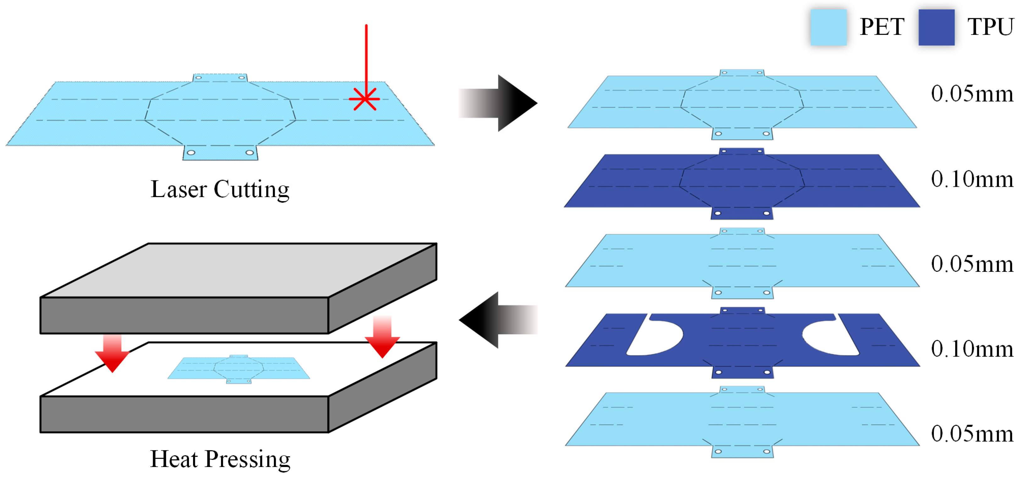
Figure 2, where five layers with different cutting patterns are overlapped. The top two layers are cut with the crease pattern, which not only facilitates the folding process but also makes one side of the bottom air chamber thicker. By flipping the gripper to alter the relative positions of the two parts, the gripper’s grasping morphing can be changed. After processing the patterns on the five layers using laser cutting, the layers are then stacked in sequence. Then, a heat press machine is used to heat up and press the layers at 160 °C for 20 s. Two polytetrafluoroethylene (PTFE) tubes, serving as airways with a diameter of 0.6 mm, are fixed within the reserved channels by UV glue, which can also seal the air chambers. A syringe is used to control the volume of air injected into the air chamber. Additionally, a manometer can be connected to monitor the pressure within the air chamber.
2.2. Dual-Morphing Origami Gripper Model
The grasping of the dual-morphing origami gripper comprises two distinct phases: first, a precise and rigid folding phase, and subsequently, a flexible deformation phase due to the inflation of its air chambers. A separate analysis was performed for each of these two phases to precisely control the gripper’s motion characteristics throughout the grasping operation.
2.2.1. Rigid Folding Phase
Leveraging the crease pattern’s symmetrical properties, a coordinate system is strategically positioned, as illustrated in
Figure 3, to analyze the rigid folding using only the top-right quadrant. In order to quantify the folding state of the gripper, the sine of the dihedral angle
, which represents the angle between the side plane and the horizontal plane, is considered a key parameter in the modeling. Utilizing the configuration parameter formulas for Arc-Miura [
31] and the sector angles previously indicated in the crease pattern, we obtain the following:
where
is the edge angle along the
x-axis and
is the dihedral angle of the adjacent plane along the
y-axis. In light of geometric principles, it is understood that the collective measure of angles
and
sums to
radians. Consequently, we can obtain the following:
and
The feature points of the top-right quadrant, as illustrated in
Figure 3, are initially positioned on the
xy plane. By employing the above formulas, the spatial coordinates of each point throughout the folding process can be calculated. These coordinates are tabulated in
Table 1.
2.2.2. Flexible Deformation Phase
During the inflation of the air chamber, the origami sheet can be divided into two regions. One region experiences a noticeable change in surface curvature due to the inflation of the air chamber. The other region undergoes a rotational motion relative to its initial position, as illustrated by the blue-shaded area marked in
Figure 4a. The air chamber, indicated by the yellow shaded area, is designed to have a geometry that includes a semicircular segment of radius
and a rectangular section of width
. The length of the air chamber is the sum of
and
, while its width is the diameter of the semicircular segment (i.e.,
).
The influence of the air chamber’s design parameters needs to be analyzed in advance to select the design parameters of the air chamber. This was performed by using the explicit dynamic procedure of the finite element software ABAQUS 2023. Eight-node hexahedral solid elements were employed, and the meshes were created using sweeping technology. The interaction between different layers was modeled using the “Tie” constraint to ensure cohesive behavior across the layers. A pressure load of 150 kPa was applied to the inner wall of the air chamber to simulate its inflation. It should be noted that in finite element simulations, applying pressure to a thin film might lead to wrinkling, a phenomenon that is less apparent in real-world experiments. Since this issue is not the primary focus of our study, and our goal is to analyze the trends in deformation changes, we amplified the material stiffness and applied pressure in the simulation to minimize the simulation wrinkling while preserving the dominated inflation and rotation behavior. In the following experiments, unless otherwise noted, the air chamber is inflated with 10 mL of air (reaching an internal pressure of 15 kPa when and ).
To evaluate the extent of air chamber inflation and the degree of relative rotation at its edge, we analyzed the deformation data from the bottom surface along the red dashed line in
Figure 4a. An example is shown in
Figure 4b, where the black line represents the deformation, the blue dashed line indicates the lowest point within the air chamber (reflecting the extent of inflation), and the green dashed line marks the gripper’s end (indicating the degree of relative rotation).
Figure 4c illustrates the variation in the
z-axis height at the end of the gripper with different radius
and width
. The orange line (
) and the red line (
) are plotted separately in
Figure 4d,e, labeled as “End”. In addition, the lowest point within the air chamber is included in these graphs, labeled as “AC” to evaluate the extent of its inflation. It is clear from these figures that, when the chamber length (
) remains constant, an increase in the radius results in a significant decrease in the z-axis height at the gripper’s end, indicating an increased relative rotation at the edges. Moreover, when the width of the air chamber (
) is kept constant but
increases, the z-axis height at the gripper’s tip initially decreases before it subsequently increases.
We also theoretically calculated the deflection of the gripper’s end induced by the air chamber’s inflation based on a cantilever beam model. The detailed analysis is provided in
Appendix A. The vertical and horizontal displacements at the end of the air chamber are respectively
and
where
EI is the bending rigidity,
is the equivalent uniformly distributed force applied on the upper surface,
is that on the lower surface,
is the equivalent concentrated force,
is the rotation angle, and
and
where
is the curvature of the beam.
By substituting the parameters and applying the tangency condition to the obtained results, we calculated the deflection at the gripper’s end, as shown by the red dashed lines in
Figure 4d,e. It should be noted that, despite its simplification based on the large-deflection straight beam model, the model can acceptably capture the deflection of the gripper’s end induced by the air chamber’s inflation.
3. Results
In this section, several parameters of the proposed dual-morphing gripper were tested to determine their influence on the gripper’s performance, specifically regarding its deformation and the magnitude of the force it can exert during the inflation of the air chambers. The gripper’s capability and adaptability were further demonstrated through grasping experiments involving daily objects with varying geometries, surface roughness, and masses.
3.1. Characterization of Dual-Morphing Gripper
One important metric for evaluating the grasping performance of a gripper is the range of object sizes it can hold, which is primarily determined by the minimum gap between the gripper’s terminal ends. In this design, the gap is mainly affected by the deformation caused by air chamber inflation. Therefore, we will experimentally examine the relationship between the air chamber’s configuration parameters and its deformation.
As shown in
Figure 4a, the parameters of the semi-circle rectangle shape are defined by the circular radius
and the rectangular width
. Digital Image Correlation (DIC) technology was employed to measure the
z-axis height of the gripper’s terminal end (
Figure 5).
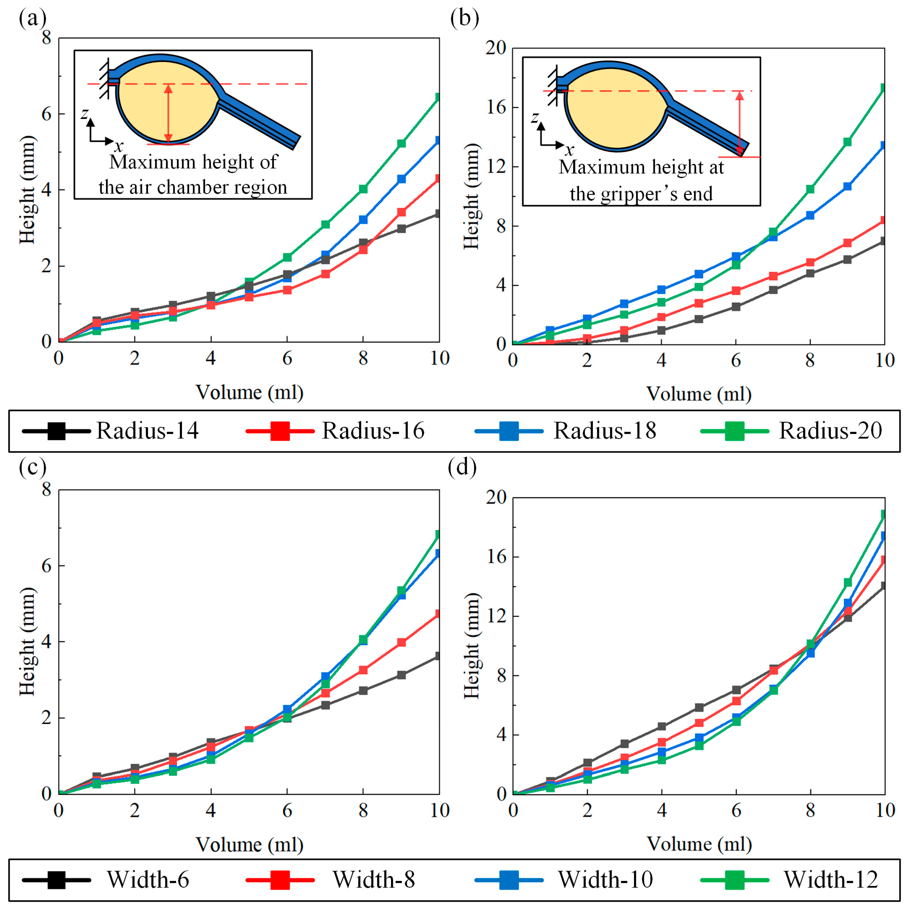
Experiments were conducted for air chambers with different circular radii
r and volumes of input gas while keeping the length constant (
Figure 6a,b). Additionally, air chambers with constant radius
but different rectangular width
w were also considered (
Figure 6c,d). An increase in radius
under constant length leads to a decrease in the inflation rate of the air chamber but enhances the rotation of the terminal panel. This is partly due to the increased area of the air chamber that leads to greater inflation. Additionally, the increased width of the air chamber extends the boundary line acting on the terminal panel, thereby improving the grasping performance. Under a constant radius, increasing rectangular width
also enhances the rotation of the terminal panel, albeit to a lesser degree. This is because an increase in rectangular width
increases the area of the air chamber but also reduces the length of the terminal panel. In addition, under the same angle of rotation, shorter panels result in lower heights at their ends.
3.2. Grasping Force
Another metric for evaluating the grasping performance of a gripper is the magnitude of the grasping force. When the surface roughness remains unchanged, the magnitude of the frictional force is proportional to the magnitude of the normal force. The inflation of the air chamber not only induces a relative rotation at the terminal panel but also increases the bending stiffness of the terminal panel, thereby enhancing the normal force exerted on the object.
To demonstrate the output force of the pneumatic actuation, a fully extended gripper is fixed to a platform, as shown in
Figure 7a. A high-precision force sensor (DYZ-100, DYSENSOR, Bengbu, China) was positioned below the gripper’s terminal end to measure the output force. We measured the output force in the middle region at the gripper’s terminal end during air chamber inflation with different shape parameters (see
Figure 7b,c). Under constant-length conditions, an increase in the radius, which in turn increases the air chamber’s surface area, significantly enhances the output force at the gripper’s terminal end. Similarly, under constant-radius conditions, an increase in the width of the rectangular section also enhances the output force. This is due to the significant increase in stiffness of the air chamber region when inflated. Increasing the width of the rectangle expands the air chamber region, which enhances the bending stiffness at the gripper’s end. This also enhances its output force. Furthermore, since the creases divide the terminal panel into three regions, the output forces in the upper and lower regions are also measured, as shown in
Figure 7d. Although the output force of the central panel is slightly higher compared to the other two, the difference in output force between them is not significant. This indicates that all three regions of the terminal panel play important roles in the grasping operation.
3.3. Grasping Test
To facilitate the demonstration of the gripper’s grasping capabilities, we modify an open-source robotic arm controlled by Arduino Uno [
32]. The original gripper module of the robotic arm is replaced with a platform capable of mounting our dual-morphing gripper, as shown in
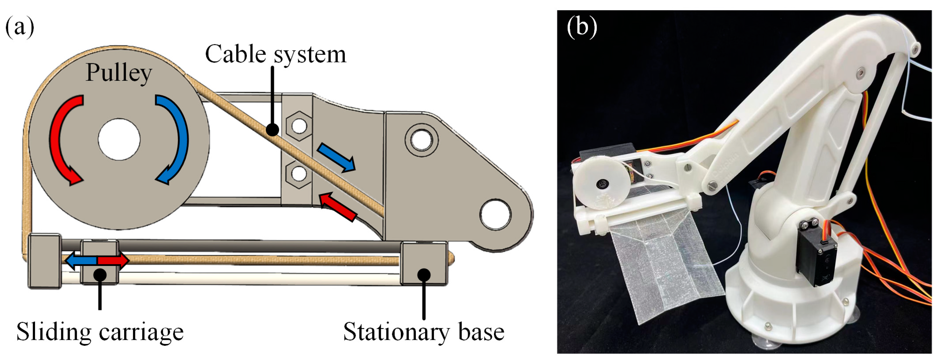
Figure 8a. One end of the dual-morphing gripper is fixed to the platform’s stationary base, while the other end is attached to a sliding carriage. The platform employs a tendon-driven mechanism, where a cable system converts the rotational motion from the pulley into linear motion of the sliding carriage. This linear motion drives the folding and unfolding of the gripper structure. The modified robotic arm with the installed gripper is shown in
Figure 8b. The gripper employed in the experiment has an unfolded length of 180 mm and a width of 80 mm.
As shown in
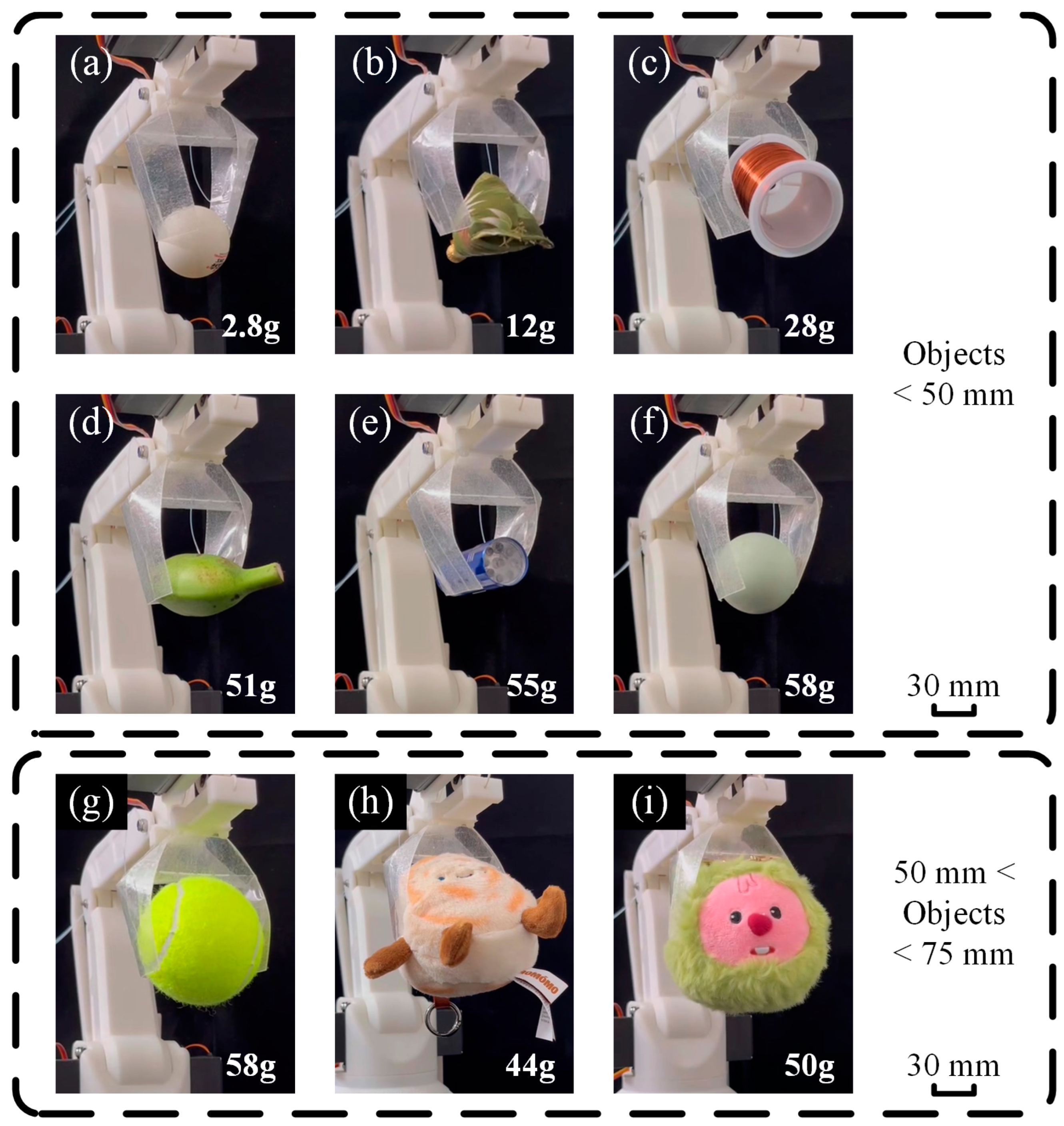
Figure 9, the gripper can easily grasp a 2.8 g table tennis ball (
Figure 9a) and stably grasp a 58 g egg (
Figure 9f). Weighing only 4.5 g, the proposed gripper can lift objects more than ten times of its own weight. The gripper was also utilized to grasp with different masses, shapes, and surface roughness, thus demonstrating the gripper’s robustness and adaptability.
We also test its grasping capability in the inward grasping morphing, as shown in
Figure 10. Larger objects are grasped as shown in
Figure 10a,b, while objects with smooth surfaces are grasped in
Figure 10c,d.
The experimental results indicate that the proposed gripper, with its two grasping morphings (i.e., outward and inward), possesses strong grasping capabilities and is adaptable to various geometries and surface conditions. The selection of different grasping morphings effectively expands the range of object sizes that can be grasped. Details of the grasping process for some of the objects shown in
Figure 9 and
Figure 10 can be found in
Video S1 in the Supplementary Materials.
4. Discussion
A comparison between the dual-morphing origami gripper and other origami grippers is shown in
Table 2. Our approach offers a new grasping morphing by integrating pneumatic structures into the origami gripper design. This allows it to grasp larger objects and improves its adaptability in different grasping scenarios compared to other origami grippers. Furthermore, the proposed gripper uses relatively fewer types of materials, which reduces manufacturing complexity.
The dual-morphing gripper introduced in this study utilizes plastic films of different thicknesses for lamination. The selection of the film thickness significantly influences the gripper’s grasping performance. If the films are too thin, most of the pressure will be used for deformation during the expansion of the air chamber, leading to inefficiencies in energy transfer and a weakening of the gripper’s force output. Additionally, excessively thin films will reduce the overall bending stiffness of the structure, thereby diminishing the gripper’s grasping capability. On the other hand, carelessly increasing the thickness of the PET films in the hope of enhancing structural stability brings new challenges during the heat-pressing process. Specifically, very thick PET materials experience greater thermal contraction upon cooling, leading to significant dimensional inaccuracies. This not only hinders their precise alignment with other components but also drastically reduces the success rate of replicating standard samples in a laboratory environment. Furthermore, when PET films are too thick, the adhesive strength at the interface with TPU can be insufficient, leading to delamination and failure at the crease lines.
Through extensive experimental validation, we identified a moderate thickness selection strategy. This strategy aims to maintain the necessary mechanical properties, such as adhesive strength and bending stiffness, of the gripper while preventing the negative effects associated with overly thick PET materials. Accordingly, the overall manufacturing success rate and practical performance of the gripper can be significantly enhanced with the suggested film thickness.
5. Conclusions
In this work, we propose a lightweight dual-morphing gripper based on the Miura-ori pattern, which innovatively combines the advantages of both the origami structure and pneumatic actuation. To enhance the precision of the gripper’s manipulation, the Miura-ori pattern is employed to form the main body of the gripper. To reduce the volume of the pneumatic actuation part, the air chambers were fabricated using plastic films with different cutting patterns and bonded together through heat-pressing. The multi-layer film composite structure of the gripper has a thickness of only 0.35 mm, significantly improving its maneuverability and operational capability in confined spaces. Due to the different thickness of the upper and lower layers of the air chamber, the gripper’s end section rotates in a specific direction upon inflation. This characteristic enables the gripper to operate in two distinct grasping morphings, the outward grasping morphing and the inward grasping morphing.
Through finite element simulations and theoretical analysis, we explored the parameter selection for the air chamber. With a constant air chamber length, deformation increases as radius increases. At constant radius , deformation initially increases with width but then decreases as continues to increase. Using DIC technology and a force sensor, we analyzed the deformations and measured the output forces for different parameter combinations. Our findings confirm that within a range, both the deformation and output force at the gripper’s end increase with respect to both and . The analysis shows that and provide the best performance. Grasping tests were conducted using these parameters. Grasping tests on various objects show the gripper’s excellent grasping capability, including its ability to lift objects more than ten times of its own weight. The gripper also exhibits good adaptability to a wide range of irregular shapes and surface roughness of everyday objects.
The heat-pressing method used in this study to combine origami design with pneumatic actuation also provides a new route for designing and fabricating origami grippers. This approach not only preserves the adaptability of flexible grippers but also provides a different grasping mode to enhance their adaptability to various objects. Future research could further explore the combination of various materials and actuation methods to further improve the functionality and performance of soft grippers. We believe that this study, including the concept of origami cutting patterns, the use of layered plastic films, and the asymmetric thickness, will provide valuable design insights for developing more flexible and adaptable grippers capable of handling a wider range of object characteristics.
Author Contributions
Conceptualization, T.Y. and K.-C.C.; methodology, T.Y. and S.-F.X.; software, T.Y.; validation, T.Y. and S.-F.X.; formal analysis, S.-F.X.; investigation, T.Y. and S.-F.X.; writing—original draft preparation, T.Y. and S.-F.X.; writing—review and editing, K.-C.C.; visualization, T.Y.; supervision, K.-C.C.; project administration, K.-C.C.; funding acquisition, K.-C.C. All authors have read and agreed to the published version of the manuscript.
Funding
This study was funded by financial support from the National Natural Science Foundation of China (NSFC) (No. 12372094), State Key Laboratory of Structural Analysis, Optimization and CAE Software for Industrial Equipment (Dalian University of Technology) (NO. GZ24114), the open foundation of Hubei Key Laboratory of Theory and Application of Advanced Materials Mechanics (Wuhan University of Technology) (No. TAM202304), the Scientific Research Fund of Zhejiang University (XY2023049) and the Zhejiang Provincial Natural Science Foundation of China (Z25A020011).
Data Availability Statement
Data are contained within the article.
Conflicts of Interest
The authors declare no conflicts of interest.
Abbreviations
The following abbreviations are used in this manuscript:
| PET | Polyethylene terephthalate |
| TPU | Thermoplastic polyurethanes |
| DIC | Digital Image Correlation |
Appendix A
For ease of calculation, the gripper is modeled as a cantilever beam and we focus only on its deformation within the
xOz plane and neglect the effects of deformations in other directions. As shown in
Figure A1a, the thin film edges are subjected to linear tension vectors
, gas pressure
, with a normal vector
pointing in the
z direction. According to Green’s theorem and the force equilibrium analysis, we have the following:
Figure A1.
(a) Force analysis of thin film expansion; (b) equivalent force diagram of cantilever beam; (c) deformation diagram of cantilever beam.
Figure A1.
(a) Force analysis of thin film expansion; (b) equivalent force diagram of cantilever beam; (c) deformation diagram of cantilever beam.
The force model of the cantilever beam structure is shown in
Figure A1b, where the action of air pressure on the gripper is equivalent to a uniformly distributed force
, and the action of film edge tension on the gripper is equivalent to a homogeneous stress
and a concentrated force
. According to Equation (A1), we have the following:
and
where
and
are the estimated approximate coefficients of the equivalent uniformly distributed forces from air pressure and film edge tension [
38,
39,
40].
As shown in
Figure A1c, only the deformation of the air chamber part, i.e., the segment
OA of the cantilever beam, is considered. The vertical displacement at point
A is
, the horizontal displacement is
, and the rotation angle is
. The deformation of the cantilever beam can be considered as the case of small deformation and large deflection. The horizontal projection length of the deformed segment
OA is
. From
Figure A1b, the expression for the bending moment can be written as
The differential equation for the deflection curve of a straight beam bending in the plane is given by [
41]
The
AB segment of the cantilever beam is not subjected to any forces, so it is tangent to the
OA segment at point
A, where the boundary conditions are
Combining Equations (A5)–(A7), we obtain the functional relationship between the rotation angle and curvature
of the cantilever beam:
where
By solving Equations (A8) and (A9) simultaneously, we can obtain the vertical and horizontal displacements at point A, respectively, as follows:
and
where
References
- Liu, Y.; Hou, J.; Li, C.; Wang, X. Intelligent Soft Robotic Grippers for Agricultural and Food Product Handling: A Brief Review with a Focus on Design and Control. Adv. Intell. Syst. 2023, 5, 2300233. [Google Scholar] [CrossRef]
- Sut, D.J.; Sethuramalingam, P. Soft Manipulator for Soft Robotic Applications: A Review. J. Intell. Robot Syst. 2023, 108, 10. [Google Scholar] [CrossRef]
- Li, Y.; Chen, Y.; Yang, Y.; Wei, Y. Passive Particle Jamming and Its Stiffening of Soft Robotic Grippers. IEEE Trans. Robot. 2017, 33, 446–455. [Google Scholar] [CrossRef]
- Li, Y.; Sun, B.; Chen, T.; Hu, B.; Guo, M.; Li, Y. Design and Prototyping of a Novel Gripper Using PVC Gel Soft Actuators. Jpn. J. Appl. Phys. 2021, 60, 087001. [Google Scholar]
- Guo, J.; Elgeneidy, K.; Xiang, C.; Lohse, N.; Justham, L.; Rossiter, J. Soft Pneumatic Grippers Embedded with Stretchable Electroadhesion. Smart Mater. Struct. 2018, 27, 055006. [Google Scholar] [CrossRef]
- Zhang, Z.; Long, Y.; Chen, G.; Wu, Q.; Wang, H.; Jiang, H. Soft and Lightweight Fabric Enables Powerful and High-Range Pneumatic Actuation. Sci. Adv. 2023, 9, eadg1203. [Google Scholar] [PubMed]
- Catalano, M.G.; Grioli, G.; Farnioli, E.; Serio, A.; Piazza, C.; Bicchi, A. Adaptive Synergies for the Design and Control of the Pisa/IIT SoftHand. Int. J. Robot. Res. 2014, 33, 768–782. [Google Scholar]
- Rothemund, P.; Ainla, A.; Belding, L.; Preston, D.J.; Kurihara, S.; Suo, Z.; Whitesides, G.M. A Soft, Bistable Valve for Autonomous Control of Soft Actuators. Sci. Robot. 2018, 3, eaar7986. [Google Scholar] [CrossRef]
- Deimel, R.; Brock, O. A Novel Type of Compliant and Underactuated Robotic Hand for Dexterous Grasping. Int. J. Robot. Res. 2016, 35, 161–185. [Google Scholar] [CrossRef]
- Firouzeh, A.; Paik, J. Grasp Mode and Compliance Control of an Underactuated Origami Gripper Using Adjustable Stiffness Joints. IEEE/ASME Trans. Mechatron. 2017, 22, 2165–2173. [Google Scholar] [CrossRef]
- Chen, S.; Pang, Y.; Cao, Y.; Tan, X.; Cao, C. Soft Robotic Manipulation System Capable of Stiffness Variation and Dexterous Operation for Safe Human–Machine Interactions. Adv. Mater. Technol. 2021, 6, 2100084. [Google Scholar] [CrossRef]
- Liu, S.; Wang, F.; Liu, Z.; Zhang, W.; Tian, Y.; Zhang, D. A Two-Finger Soft-Robotic Gripper with Enveloping and Pinching Grasping Modes. IEEE/ASME Trans. Mechatron. 2020, 26, 146–155. [Google Scholar] [CrossRef]
- Jittungboonya, P.; Maneewarn, T. Grasping with a Tube-Feet Inspired Soft Gripper. In Proceedings of the 2019 First International Symposium on Instrumentation, Control, Artificial Intelligence, and Robotics (ICA-SYMP), Bangkok, Thailand, 16–18 January 2019; pp. 147–150. [Google Scholar]
- Zhao, Y.; Zhang, J.; Zhang, S.; Zhang, P.; Dong, G.; Wu, J.; Zhang, J. Transporting Dispersed Cylindrical Granules: An Intelligent Strategy Inspired by an Elephant Trunk. Adv. Intell. Syst. 2023, 5, 2300182. [Google Scholar] [CrossRef]
- Hoang, T.T.; Phan, P.T.; Thai, M.T.; Lovell, N.H.; Do, T.N. Bio-Inspired Conformable and Helical Soft Fabric Gripper with Variable Stiffness and Touch Sensing. Adv. Mater. Technol. 2020, 5, 2000724. [Google Scholar]
- Wang, W.; Li, C.; Cho, M.; Ahn, S.-H. Soft Tendril-Inspired Grippers: Shape Morphing of Programmable Polymer–Paper Bilayer Composites. ACS Appl. Mater. Interfaces 2018, 10, 10419–10427. [Google Scholar]
- Li, L.; He, S.; Qi, Q.; Zeng, J.; Kang, S.; Endo, G.; Nabae, H.; Ma, S.; Suzumori, K. PEGrip: A Plant-Tendril-Inspired Passive Entanglement Gripper Enabling Fail-Safe Grasping. IEEE Robot. Autom. Lett. 2024, 9, 7039–7046. [Google Scholar]
- Yang, M.; Cooper, L.P.; Liu, N.; Wang, X.; Fok, M.P. Twining Plant Inspired Pneumatic Soft Robotic Spiral Gripper with a Fiber Optic Twisting Sensor. Opt. Express 2020, 28, 35158. [Google Scholar] [CrossRef] [PubMed]
- Takahashi, T.; Suzuki, M.; Aoyagi, S. Octopus Bioinspired Vacuum Gripper with Micro Bumps. In Proceedings of the 2016 IEEE 11th Annual International Conference on Nano/Micro Engineered and Molecular Systems (NEMS), Sendai, Japan, 17–20 April 2016; pp. 508–511. [Google Scholar]
- Xie, Z.; Domel, A.G.; An, N.; Green, C.; Gong, Z.; Wang, T.; Knubben, E.M.; Weaver, J.C.; Bertoldi, K.; Wen, L. Octopus Arm-Inspired Tapered Soft Actuators with Suckers for Improved Grasping. Soft Robot. 2020, 7, 639–648. [Google Scholar] [CrossRef]
- Tsugami, Y. Development of Universal Parallel Gripper Using Reformed Magnetorheological Fluid. In Proceedings of the 2017 11th Asian Control Conference (ASCC), Gold Coast, QLD, Australia, 17–20 December 2017. [Google Scholar]
- Mathew, B.C.; Bharatpatil, V.; Anilchamoli; Raikwar, M.; Negi, M.S.; Singh, H. Compliant Mechanism and Origami Usage in Aerospace and Space Application. IOP Conf. Ser. Earth Environ. Sci. 2021, 775, 012008. [Google Scholar] [CrossRef]
- Ahmed, A.R.; Gauntlett, O.C.; Camci-Unal, G. Origami-Inspired Approaches for Biomedical Applications. ACS Omega 2021, 6, 46–54. [Google Scholar] [CrossRef]
- Boatti, E.; Vasios, N.; Bertoldi, K. Origami Metamaterials for Tunable Thermal Expansion. Adv. Mater. 2017, 29, 1700360. [Google Scholar] [CrossRef]
- Rus, D.; Tolley, M.T. Design, Fabrication and Control of Origami Robots. Nat. Rev. Mater. 2018, 3, 101–112. [Google Scholar] [CrossRef]
- Yan, W.; Li, S.; Deguchi, M.; Zheng, Z.; Rus, D.; Mehta, A. Origami-Based Integration of Robots That Sense, Decide, and Respond. Nat. Commun. 2023, 14, 1553. [Google Scholar] [CrossRef] [PubMed]
- Suzuki, H.; Wood, R.J. Origami-Inspired Miniature Manipulator for Teleoperated Microsurgery. Nat. Mach. Intell. 2020, 2, 437–446. [Google Scholar] [CrossRef]
- Felton, S.; Tolley, M.; Demaine, E.; Rus, D.; Wood, R. A Method for Building Self-Folding Machines. Science 2014, 345, 644–646. [Google Scholar] [CrossRef]
- Miyashita, S.; Meeker, L.; Tolley, M.T.; Wood, R.J.; Rus, D. Self-Folding Miniature Elastic Electric Devices. Smart Mater. Struct. 2014, 23, 094005. [Google Scholar] [CrossRef]
- Schenk, M.; Guest, S.D. Origami Folding: A Structural Engineering Approach. In Origami; CRC Press: Boca Raton, FL, USA, 2011; p. 16. [Google Scholar]
- Gattas, J.M.; Wu, W.; You, Z. Miura-Base Rigid Origami: Parameterizations of First-Level Derivative and Piecewise Geometries. J. Mech. Des. 2013, 135, 111011. [Google Scholar] [CrossRef]
- Xiao, Z. Dolphin Robotic Arm. Available online: https://x509p6c8to.feishu.cn/docx/FeMndRrzRommxGxTkFscJ0zKnKh (accessed on 27 November 2024).
- Liu, J.; Chen, Z.; Wen, G.; He, J.; Wang, H.; Xue, L.; Long, K.; Xie, Y.M. Origami Chomper-Based Flexible Gripper with Superior Gripping Performances. Adv. Intell. Syst. 2023, 5, 2300238. [Google Scholar] [CrossRef]
- Li, S.; Stampfli, J.J.; Xu, H.J.; Malkin, E.; Diaz, E.V.; Rus, D.; Wood, R.J. A Vacuum-Driven Origami “Magic-Ball” Soft Gripper. In Proceedings of the 2019 International Conference on Robotics and Automation (ICRA), Montreal, QC, Canada, 20–24 May 2019; pp. 7401–7408. [Google Scholar]
- Mathew, B.P.; Devasia, F.; Asok, A.; Jayadevu, P.R.; Baby, R. Implementation of an Origami Inspired Gripper Robot for Picking Objects of Variable Geometry. Mater. Today Proc. 2022, 58, 176–183. [Google Scholar] [CrossRef]
- Wang, Z.; Torigoe, Y.; Hirai, S. A Prestressed Soft Gripper: Design, Modeling, Fabrication, and Tests for Food Handling. IEEE Robot. Autom. Lett. 2017, 2, 1909–1916. [Google Scholar] [CrossRef]
- Yoo, S.; Kim, J.; Park, J.; Cha, Y. Design and Analysis of Origami-Based Multimodal Actuator Capable of Linear and Bending Motion. IEEE Robot. Autom. Lett. 2024, 9, 151–158. [Google Scholar] [CrossRef]
- Guo, X. Large deformation analysis for a cylindrical hyperelastic membrane of rubber-like material under internal pressure. Rubber Chem. Technol. 2001, 74, 100–115. [Google Scholar] [CrossRef]
- Patil, A.; DasGupta, A. Finite inflation of an initially stretched hyperelastic circular membrane. Eur. J. Mech. A/Solids 2013, 41, 28–36. [Google Scholar]
- Sirotti, S.; Pelliciari, M.; Aloisio, A.; Tarantino, A.M. Analytical pressure–Deflection curves for the inflation of pre-stretched circular membranes. Eur. J. Mech. A/Solids 2023, 97, 104831. [Google Scholar]
- Boresi, A.P.; Schmidt, R.J. Advanced Mechanics of Materials; John Wiley & Sons: Hoboken, NJ, USA, 2002. [Google Scholar]
Figure 1.
(a) “Outward grasping” morphing. (b) “Inward grasping” morphing. (c) A dual-morphing origami gripper prototype. (d) The crease pattern of the dual-morphing gripper.
Figure 1.
(a) “Outward grasping” morphing. (b) “Inward grasping” morphing. (c) A dual-morphing origami gripper prototype. (d) The crease pattern of the dual-morphing gripper.
Figure 2.
The origami structure is fabricated using five layers: three layers of PET, each with a thickness of 0.05 mm, and two sandwiched layers of TPU, each with a thickness of 0.1 mm.
Figure 2.
The origami structure is fabricated using five layers: three layers of PET, each with a thickness of 0.05 mm, and two sandwiched layers of TPU, each with a thickness of 0.1 mm.
Figure 3.
A coordinate system is established for the top-right quadrant as illustrated in the top, and the folded gripper is shown in the right figure.
Figure 3.
A coordinate system is established for the top-right quadrant as illustrated in the top, and the folded gripper is shown in the right figure.
Figure 4.
(a) The selected part for finite element modeling. (b) A deformation example at and . (c) The variation in the z-axis at the end of the gripper with different radius and width . (d) The length of the air chamber () remains constant, varying radius r. (e) Radius remains constant, varying width .
Figure 5.
Digital Image Correlation (DIC) technology involves using two cameras to capture images simultaneously, which are then post-processed to obtain deformation data.
Figure 5.
Digital Image Correlation (DIC) technology involves using two cameras to capture images simultaneously, which are then post-processed to obtain deformation data.
Figure 6.
When and varying radius , (a) the maximum height of the air chamber region and (b) the maximum height at the gripper’s end. When and varying width , (c) the maximum height of the air chamber region and (d) the maximum height at the gripper’s end.
Figure 6.
When and varying radius , (a) the maximum height of the air chamber region and (b) the maximum height at the gripper’s end. When and varying width , (c) the maximum height of the air chamber region and (d) the maximum height at the gripper’s end.
Figure 7.
(a) Test platform. (b) and varying radius . (c) and varying width . (d) For and , the output force at different regions of the gripper’s end is measured.
Figure 7.
(a) Test platform. (b) and varying radius . (c) and varying width . (d) For and , the output force at different regions of the gripper’s end is measured.
Figure 8.
(a) An original platform designed to drive the folding motion. The arrows indicate its driving direction. (b) A modified robotic arm equipped with the dual-morphing gripper.
Figure 8.
(a) An original platform designed to drive the folding motion. The arrows indicate its driving direction. (b) A modified robotic arm equipped with the dual-morphing gripper.
Figure 9.
The outward grasping morphing for grasping a (a) table tennis ball, (b) sachet, (c) copper coil, (d) banana, (e) flashlight, (f) egg, (g) tennis ball, (h) doll 1, and (i) doll 2.
Figure 9.
The outward grasping morphing for grasping a (a) table tennis ball, (b) sachet, (c) copper coil, (d) banana, (e) flashlight, (f) egg, (g) tennis ball, (h) doll 1, and (i) doll 2.
Figure 10.
The inward grasping morphing for grasping (a) foam tape, (b) double-sided tape, (c) a cylindrical pen holder, and (d) a square pen holder.
Figure 10.
The inward grasping morphing for grasping (a) foam tape, (b) double-sided tape, (c) a cylindrical pen holder, and (d) a square pen holder.
Table 1.
Coordinates of the feature points on the gripper.
Table 1.
Coordinates of the feature points on the gripper.
| | x | y | z |
|---|
| a | | 0 | 0 |
| b | | 0 | |
| c | | | 0 |
| d | | | |
| e | | | |
| f | | | |
Table 2.
Comparison with other origami grippers.
Table 2.
Comparison with other origami grippers.
| Reference | Base Material | Grasp Morphing | Maximum Gripper Spacing (mm) | Maximum Gripping Size (mm) |
|---|
| This work | PET/TPU | Outward/
Inward | 180 | ≥170 |
| Liu et al. [33] | PVC | Outward | 192 | 165 |
| Li et al. [34] | silicone rubber/PET/SMP/PVC | Outward | 100 | 70 |
| Mathew et al. [35] | silicone rubber/plastic | Outward | 152 | 90 |
| Wang et al. [36] | rubber | Outward | 168 | 93 |
| Yoo et al. [37] | PVC/polyimide | Outward | - | 80 |
| Disclaimer/Publisher’s Note: The statements, opinions and data contained in all publications are solely those of the individual author(s) and contributor(s) and not of MDPI and/or the editor(s). MDPI and/or the editor(s) disclaim responsibility for any injury to people or property resulting from any ideas, methods, instructions or products referred to in the content. |
© 2025 by the authors. Licensee MDPI, Basel, Switzerland. This article is an open access article distributed under the terms and conditions of the Creative Commons Attribution (CC BY) license (https://creativecommons.org/licenses/by/4.0/).


