Abstract
Flexible grippers based on magnetically sensitive rubber have garnered significant research attention due to their high gripping adaptability and ease of control. However, current research designs often separate the excitation device from the flexible finger, which can lead to potential interference or damage to other electronic components in the working environment and an inability to simultaneously ensure safety and gripping performance. In this paper, we propose an integrated magnetically controlled bionic flexible gripper that combines the excitation device and the flexible finger. We derive a formula for calculating the magnetic field generated by the excitation device, model and simulate the device, and find that the optimal magnetic field effect is achieved when the core-to-coil size ratio is 1:5. Additionally, we fabricated flexible fingers with different NdFeB volume ratios and experimentally determined that a volume ratio of 20% yields relatively better bending performance. The integrated magnetically controlled bionic flexible gripper described in this paper can adaptively grasp items such as rubber, column foam, and electrical tape, achieving maximum grasping energy efficiency of 0.524 g per millitesla (g/mT). These results highlight its potential advantages in applications such as robotic end-effectors and industrial automatic sorting.
1. Introduction
With the continuous development of robotics, flexible gripping, as a robot end effector and an important component of industrial automation, has gradually attracted widespread attention [1]. Compared with traditional rigid gripping technology, flexible gripping offers a more intelligent and automated solution with a simpler control method. Therefore, it has significant research value and application potential in both academic and engineering fields [2,3].
From a technical perspective, flexible grippers can be classified into three categories: actuation-based, stiffness-adjustable, and adhesion-adjustable types [4]. Among these, actuation-based flexible grippers represent the most popular research direction. These grippers operate by bending finger-like grasping components distributed around the target object, mimicking the way human fingers bend when grasping objects. Most actuation-based flexible grippers can actively control bending, with one prominent example being fluidic elastomer actuators (FEAs) [5,6]). FEAs are one of the oldest yet most widely used types of flexible actuators, generating driving forces by applying fluids (gas or liquid) into highly deformable material-based chambers. For instance, H. K. Yap et al. [7] proposed a soft pneumatic gripper fabricated using 3D printing technology, which can generate a force of 80 N at a chamber-blocking pressure of 300 kPa. M. A. Robertson et al. [8] introduced a modular FEA system composed of multiple small FEAs, capable of producing a force of 112 N at a blocking pressure of 200 kPa. Despite the relative maturity and widespread application of pneumatic flexible grippers, they still suffer from drawbacks such as complex manufacturing processes compared to other flexible grippers, including the limited portability of air pumps and significant operational noise.
Another common smart material used for fabricating actuation-based flexible grippers is dielectric elastomer actuators (DEAs) [9,10,11]. G. K. Lau et al. [12] developed a multi-segment flexible gripper using DEAs, enabling more controllable deformation and the ability to grasp highly deformable objects such as raw eggs. Although DEAs exhibit high deformability and rapid response characteristics, they typically require applied voltages in the kilovolt range, posing risks of external discharge in both daily life and industrial applications.
A third commonly used smart material for actuation-based flexible grippers is shape memory alloys (SMAs) [13,14,15]. SMAs change shape in response to external stimuli, typically temperature variations. Y. She et al. [16] combined SMAs with silicone rubber to develop a flexible gripper resembling the shape of a human hand with programmable bending directions, capable of grasping objects ranging from cylindrical to sheet-like forms, demonstrating remarkable flexibility and adaptability. H. Il Kim et al. [17] also developed a human hand-like flexible gripper by encapsulating SMAs with glass fibers and connecting finger joints using hinge structures, achieving finger bending through SMA heating. The primary advantages of SMAs include their ability to generate significant stress and driving strain, as well as their ease of miniaturization. However, their drawbacks are equally notable, including relatively slow response times (≈3 Hz [18]) compared to other smart materials and significant hysteresis effects.
Although existing smart material-based flexible grippers have shown certain advantages, they still have significant shortcomings and struggle to perfectly combine characteristics such as safety, portability, ease of control, and fast response [19]. In recent years, magnetically sensitive rubber, as a smart material, has shown great potential in the study of flexible actuated devices due to its unique magneto-mechanical properties and flexibility [20,21]. Specifically, significant progress has been made in the research and application of new magnetically sensitive rubbers. For example, Y. Kim et al. [22] proposed a deformation-programmable method for fabricating magnetic rubber using 3D printing technology, where the printed planar sheet can be deformed into a 3D shape under the influence of a magnetic field. Qi S et al. [23] also investigated a new fabrication method by embedding magnetically sensitive rubber with different magnetization directions into a soft polymer matrix to achieve deformation programmability. This method can mimic the motion gaits of starfish, snakes, and other creatures and was demonstrated in a two-finger jig in a uniform magnetic field.
Nevertheless, magnetically sensitive rubber still faces several key technical challenges in flexible gripping research [24,25]. Firstly, there are two main types of existing magnetization schemes: one involves applying a single-source magnetic field under the object to be grasped, and the other uses a pair of coils to apply a uniform magnetic field in the working environment. However, these schemes often require increasing the magnetic field strength to enhance gripping force, which can interfere with the normal operation of other electronic components or ferrous devices in the working environment, potentially rendering them ineffective and posing a safety hazard [26]. Secondly, the research on the magnetic control performance of magnetically sensitive rubber is still in the preliminary stage and lacks systematic analysis from the perspective of flexible gripping. Particularly, for larger sizes, fully utilizing the mechanical and magnetic properties of magnetically sensitive rubber remains an urgent challenge. Finally, when multiple magnetically sensitive rubbers are combined into a flexible gripper, its overall gripping performance relies on the coordinated action of multiple fingers. However, there is a lack of comprehensive research on testing protocols and performance data for magnetically controlled flexible grippers.
Based on the aforementioned challenges, this paper focuses on a bionic flexible gripper made from magnetically sensitive rubber, aiming to enhance its gripping performance and safety through the rational design of an integrated magnetism control and actuation structure, combined with bionic principles. The research content of this paper includes the following aspects:
- Drawing on the dexterous hand and foot structures of living creatures, a rational design of a magnetically controlled bionic flexible gripper is proposed. We use SolidWorks 2022 for three-dimensional modeling and perform magnetic circuit simulations in COMSOL Multiphysics 6.0 to obtain the optimal excitation device model.
- The influencing factors on the bending properties of magnetically sensitive rubber are analyzed and identified. Magnetically sensitive rubber is prepared with different volume ratios of NdFeB and the influence of volume ratio on bending performance is investigated through experiments. The effects of different factors on the bending performance of magnetic sensitive rubber are analyzed and the change patterns are evaluated.
- A test scheme is designed for the grasping performance of the magnetically controlled bionic flexible gripper, and the effects of different size parameters and the shape of the grasped object on the grasping performance are analyzed. Grasping experiments are conducted with the magnetically controlled bionic flexible gripper to obtain and evaluate each performance index.
2. Materials and Methods
2.1. Design and Manufacture of Grippers
In this paper, a flexible gripper structure integrating a magnetron device and a flexible magnetic sensitive element is designed, drawing on the dexterity of animals’ hands and feet. The conceptual diagram of the structure is shown in Figure 1. In the non-operating state (Figure 1a), the flexible magnetic sensitive element remains in its natural state; in the operating state (Figure 1b), a magnetic field is generated by the built-in excitation device, which deforms the flexible magnetic sensitive element, thus realizing the grasping function. This integrated design not only improves gripping force but also ensures safe operation and avoids interference with electronic components in the surrounding environment.
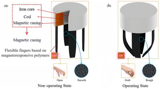
Figure 1.
Conceptual diagram of magnetically controlled bionic flexible gripper. (a) Gripper in a non-operational state. (b) Gripper in working condition.
The magnetically controlled bionic flexible gripper consists of two main components: the excitation device and the magnetically sensitive rubber. The excitation device, designed to mimic the palm of a human hand, serves as the structural foundation and generates control signals. The magnetically sensitive rubber, which functions like human fingers, responds to magnetic fields to produce movement, enabling the gripper to grasp objects effectively. Furthermore, the surface of the magnetically sensitive rubber undergoes changes in texture when exposed to a magnetic field, becoming rougher to enhance friction and improve gripping performance. This design allows the gripper to securely hold objects by leveraging the interplay between magnetic fields and surface morphology, mimicking the dexterity of a human hand. The adaptability of the gripper ensures the efficient handling of various objects, making it suitable for a wide range of applications.
2.2. Magnetic Circuit Design and Modeling of Excitation Devices
2.2.1. Magnetic Circuit Designs
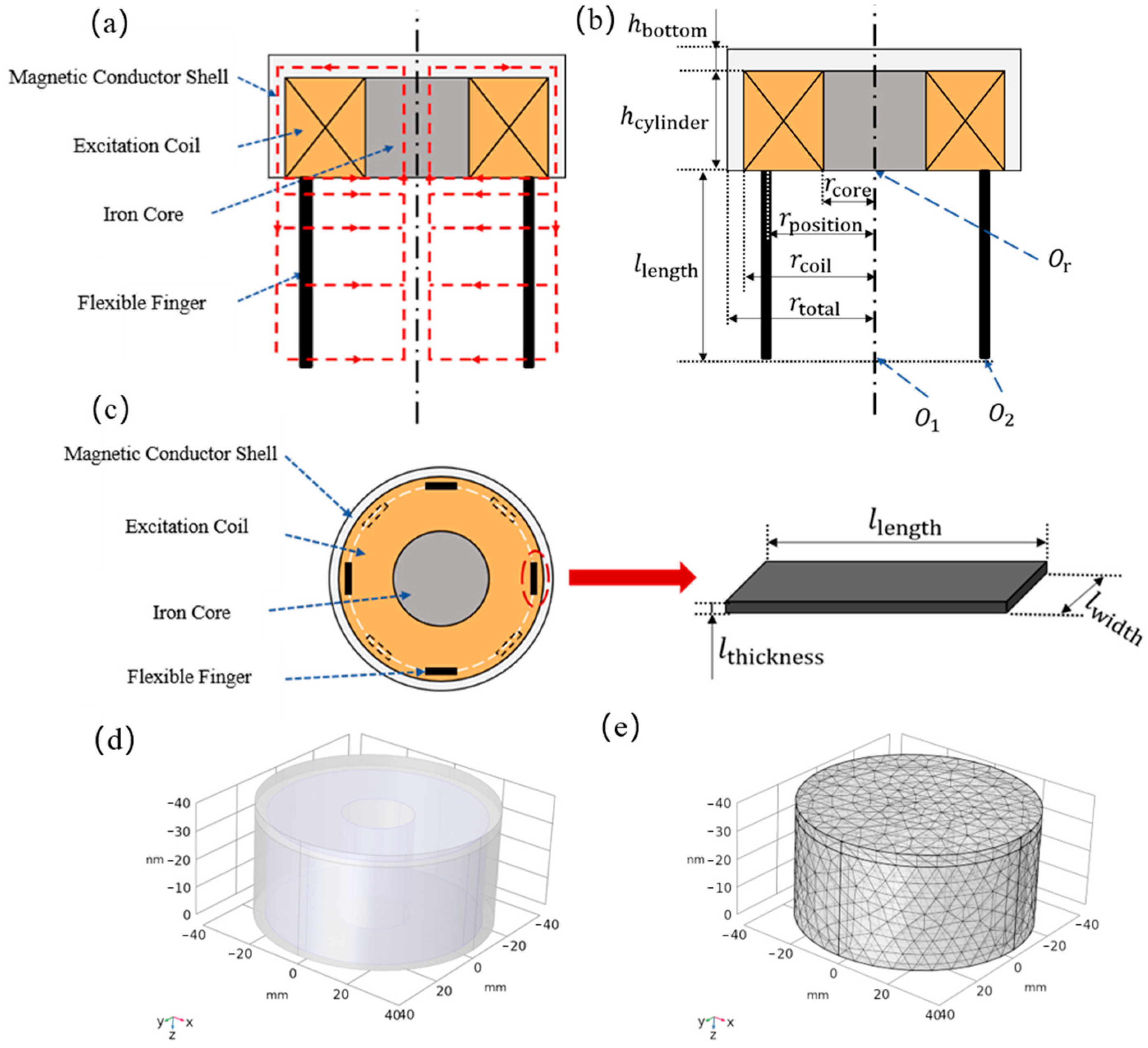
As depicted in Figure 2a, the bottom portion of the excitation device within the magnetically controlled bionic flexible gripper is left open, enabling the magnetic field to permeate through the air and reach the flexible finger. The structure of the bionic flexible gripper is symmetrically aligned around the central axis. The excitation device features a magnetically conductive casing exclusively on its upper end and sides, with the lower end remaining unobstructed. To compute the magnetic field generated by this half-open configuration, the key dimensional parameters and pivotal points have been denoted in Figure 2b.

Figure 2.
Schematic diagram of the magnetic circuit of the magnetically controlled bionic flexible gripper. (a) Schematic diagram of the magnetic circuit and dimensional parameters of the magnetically controlled bionic flexible gripper. (b) The main dimensions of the magnetically controlled bionic gripper. (c) Elevation view and finger dimensions of the magnetically controlled bionic gripper. (d) Structural modeling of the excitation device. (e) Schematic of the finite element meshing of the simulation software.
Since the rate of lateral decay of the magnetic field is small, the magnetic field strength can be roughly estimated using the Biot–Savart Law [27]. This simplified model provides a rough approximation of the magnetic field generated by the excitation device at the flexible finger, offering theoretical support for the analysis of the magnetic circuit in this integrated magnetically controlled flexible gripper. Moreover, this calculation model can be generalized to any point in the working environment, offering some reference for evaluating the safety of the magnetically controlled bionic flexible gripper.
2.2.2. Simulation Analysis of Excitation Device
To study the influence of the ratio of each part of the excitation device on the control magnetic field, a magnetic field model of the excitation device is established using the finite element simulation software COMSOL Multiphysics 6.0. The constructed model is shown in Figure 2d. The relevant parameters required for simulating the magnetic field strength are presented in Table 1.

Table 1.
Simulation key parameters of the excitation unit.
To better align with the performance of the excitation device at various sizes, the boundary conditions of the magnetic field (MF) module are set to conduct the magnetic field simulation. Additionally, the smart meshing function in COMSOL Multiphysics 6.0 is employed to discretize the excitation device model, as illustrated in Figure 2e.
2.2.3. Dimensioning and Optimization of the Excitation Unit
The control magnetic field determines the gripping force of the magnetically controlled bionic flexible gripper. To enhance the gripping force, the excitation device must be optimized to generate a stronger control magnetic field. Researcher G. P. Hatch [28] found that the ratio of the radius to the height of a cylindrical magnet influences the magnitude of the magnetic field it produces. Therefore, investigating the relationship between the internal dimensions’ ratio of the cylindrical excitation device and the magnetic field strength it generates is essential for optimizing the structure.
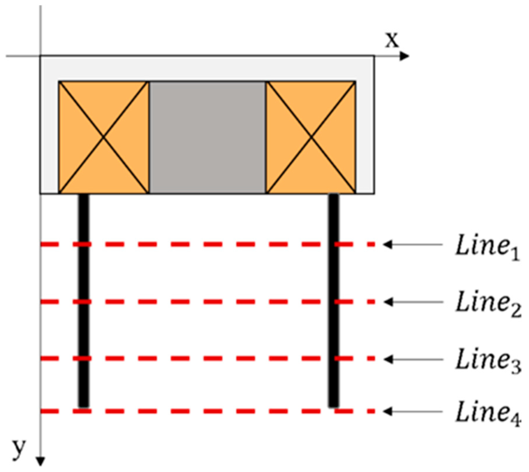
To simplify the complex calculation of the magnetic field across the entire flexible finger, a model using four line segments was established (as shown in Figure 3). This model facilitated the optimization objective of the excitation device. The structural proportions of the excitation device significantly influence the magnetic field strength it produces. Through simulation and analysis, it was found that the optimal configuration involves adjusting the size ratios between the iron core and the coil.

Figure 3.
Schematic of the line segments required to calculate the optimization objective.
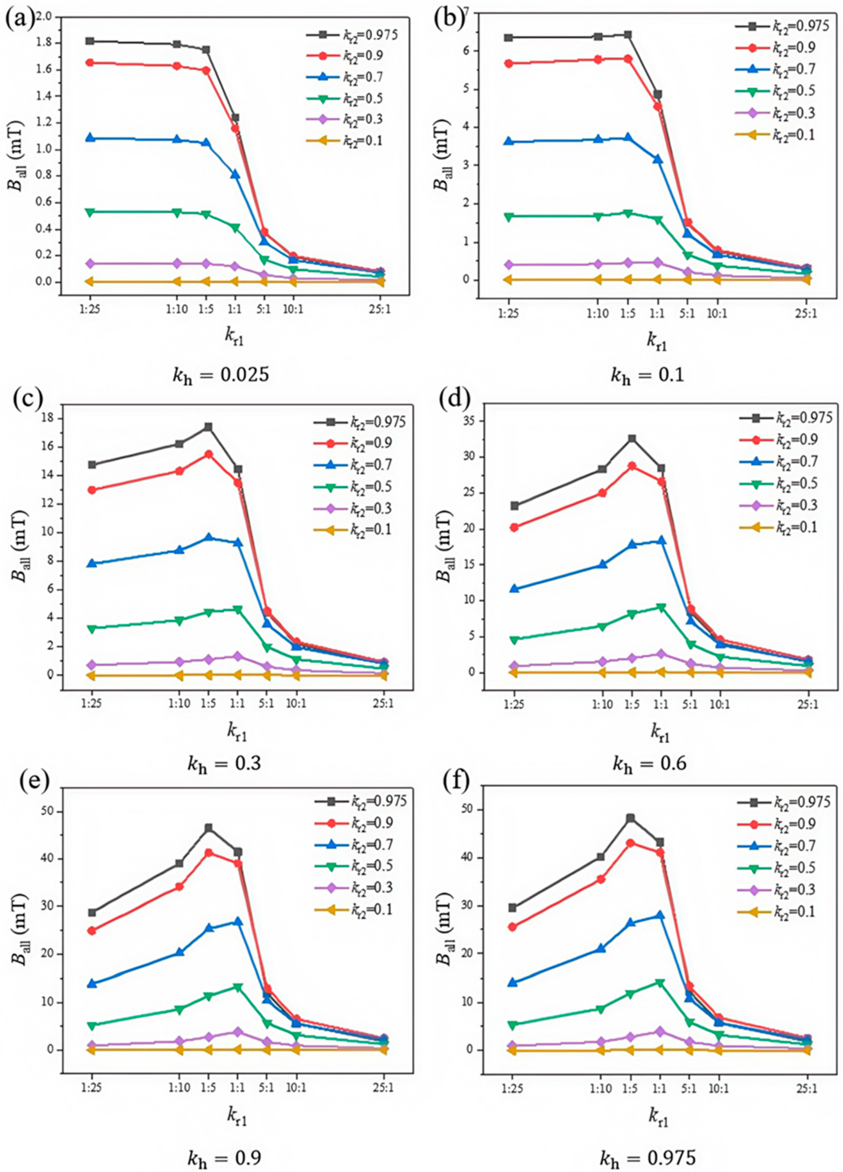
The simulation results are presented in Figure 4. and represent the ratios of component sizes relative to the overall device size, a value of 0 implies the absence of both the core and coil, while a value of 1 indicates the absence of the steel case. Similarly, due to constraints on simulation accuracy, investigations are confined within the ranges of and . It is evident from Figure 4 that , , and each exert distinct influences on the generated magnetic field. Specifically, the total magnetic induction intensity () increases with ; for a constant , also rises with . These observations collectively suggest that, in an excitation device comprising a steel case, coil, and core, a larger proportion of the coil and core leads to a greater .
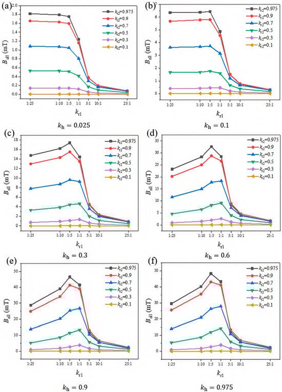
Figure 4.
Magnetic field strength versus structural parameters across varying values. (a) = 0.025; (b) = 0.1; (c) = 0.3; (d) = 0.6; (e) = 0.9; (f) = 0.975.
The relationship between and exhibits different behaviors across various ranges of . Specifically, for , decreases as increases. Conversely, within the range , no longer follows a monotonic trend; instead, it initially increases and then decreases with , peaking at . The peak value of increases with both and . Among all feasible combinations of the ratios, attains a maximum value of 48.24 mT.
In summary, the ratio of the total dimensions of the iron core and coil has the greatest influence on the magnetic field that can be produced by the excitation device. By adjusting the size ratio between the iron core and the coil, the best magnetic field can be achieved when the ratio of the difference between the radius of the iron core and the inner and outer radii of the coil is 1:5.
2.3. Gripping Mechanism Analysis of Magnetically Controlled Bionic Flexible Gripper
The ability of a gripper to grasp objects relies on the flexible fingers bending under the influence of a magnetic field. The force that causes the flexible fingers to bend is actually the interaction force between the magnetic field generated by the excitation device and the neodymium iron boron particles inside the flexible fingers. In this paper, it is assumed that all the NdFeB particles in the flexible finger are spherical dipoles of the same size and equidistant. The magnetization strength of the magnetic particles can be calculated using the Fröhlich–Kennelly formula [29,30]:
where : magnetic saturation strength of NdFeB particles; : relative magnetic permeability of NdFeB particles.
The applied magnetic field strength H can be expressed as [31]
where : the magnetic flux density.
The change in the shear modulus of magnetically sensitive rubber in the presence of a magnetic field can be expressed using the dipole model as
where R: average radius of magnetic particles; d: average distance between magnetic particles; : volume fraction of magnetic particles, which can be expressed as .
The Young’s modulus altered by the magnetic field can be expressed as
where is the Poisson’s ratio of the magnetically sensitive rubber.
Since the magnetic field generated by the excitation device is a toroidal magnetic field, it can be assumed that the applied magnetic field is always perpendicular to the surface of the flexible finger during its movement. The equivalent magnetic force per unit area applied to the magnetically sensitive rubber can be expressed as [31]
where : normal component of the magnetic field strength at the upper surface of the sample; : normal component of the magnetic field strength at the lower surface of the sample; : relative permeability of magnetically sensitive rubber composites.
where depends on the volume fraction of magnetic particles in the magnetically sensitive rubber, which can be expressed as [32].
According to Euler–Bernoulli beam theory, the deformation of a flexible finger can be expressed as
where E: Young’s modulus of the flexible finger under the influence of a magnetic field, which can be expressed as ; : Young’s modulus of the flexible finger in the absence of a magnetic field; I: the moment of inertia of the beam, which can be expressed as .
Note that EI represents the bending stiffness of the beam. It is important to recognize that Young’s modulus and the magnetic force in Equation (7) change with bending, a phenomenon known as magnetoelastic coupling. An iterative computational method can be used to solve this problem.
The initial deformation w is calculated based on the initial assumptions of the magnetic field and modulus. Subsequently, a new deformation w is calculated based on the updated magnetic field and modulus until the deformation w is less than a very small value. As can be seen from Equation (7), among length, width, and thickness, the bending angle increases with an increase in length, is unaffected by width, and decreases with an increase in thickness.
2.4. Analysis of Magnetic-Induced Surface Morphology Changes
Magnetic particles are magnetized in a magnetic field, and neodymium iron boron particles that are already magnetized will enhance their magnetization effect when the direction of the external magnetic field aligns with the direction of their magnetic dipole moment. The magnetized dipoles will then exert an interaction force on each other, which can be expressed as
where mi, mj: represent the magnetic dipole moments of magnetic particles i and j under the influence of a magnetic field; r0: the directional vector of the magnetic moment; d: the distance between the two magnetic particles.
Assuming that the magnetic dipole moment of each magnetic dipole is the same, Formula (15) can be further simplified as
where : The angle between the line connecting the center points of magnetic dipoles i and j and the direction of the external magnetic field.
From Formula (9), it can be seen that only NdFeB particles with small spacing can generate effective interaction forces between them; the interaction forces between magnetic particles with larger spacing can be neglected. Therefore, the interaction force between NdFeB particles depends on the proximity of other particles. Under the mutual action of magnetic force Fij, NdFeB particles generate magnetic induction stress σij, which can be expressed as
where : small strain of rubber.
These tiny magnetic induction stresses cause slight deformations in the rubber matrix, which quickly reach a steady state. When the initial roughness of the magneto-sensitive rubber is relatively smooth, the NdFeB particles being randomly distributed within the rubber matrix lead to uneven changes in the interaction forces Fij between these particles once a magnetic field is applied. This results in uneven magnetic induction stresses σij. Consequently, this causes non-uniform micro-strains ε in the magneto-sensitive rubber, ultimately leading to irregular deformation of what was initially a fairly smooth surface. That is, the surface roughness increases, and this roughness grows with the increase in magnetic field strength. This observation aligns with experimental results.
2.5. Optimization and Modeling of Magnetron Performance of Flexible Fingers
The flexible magnetic element is composed of magnetically sensitive rubber, a type of smart material that undergoes significant reversible changes under the influence of a magnetic field, such as variations in stiffness, damping, modulus, and surface roughness [33]. All these properties respond to changes in the applied magnetic field and, in certain cases, also induce bending deformation. Among these phenomena, magnetically controlled bending deformation and magnetically controlled surface roughness are particularly critical for grasping behavior.
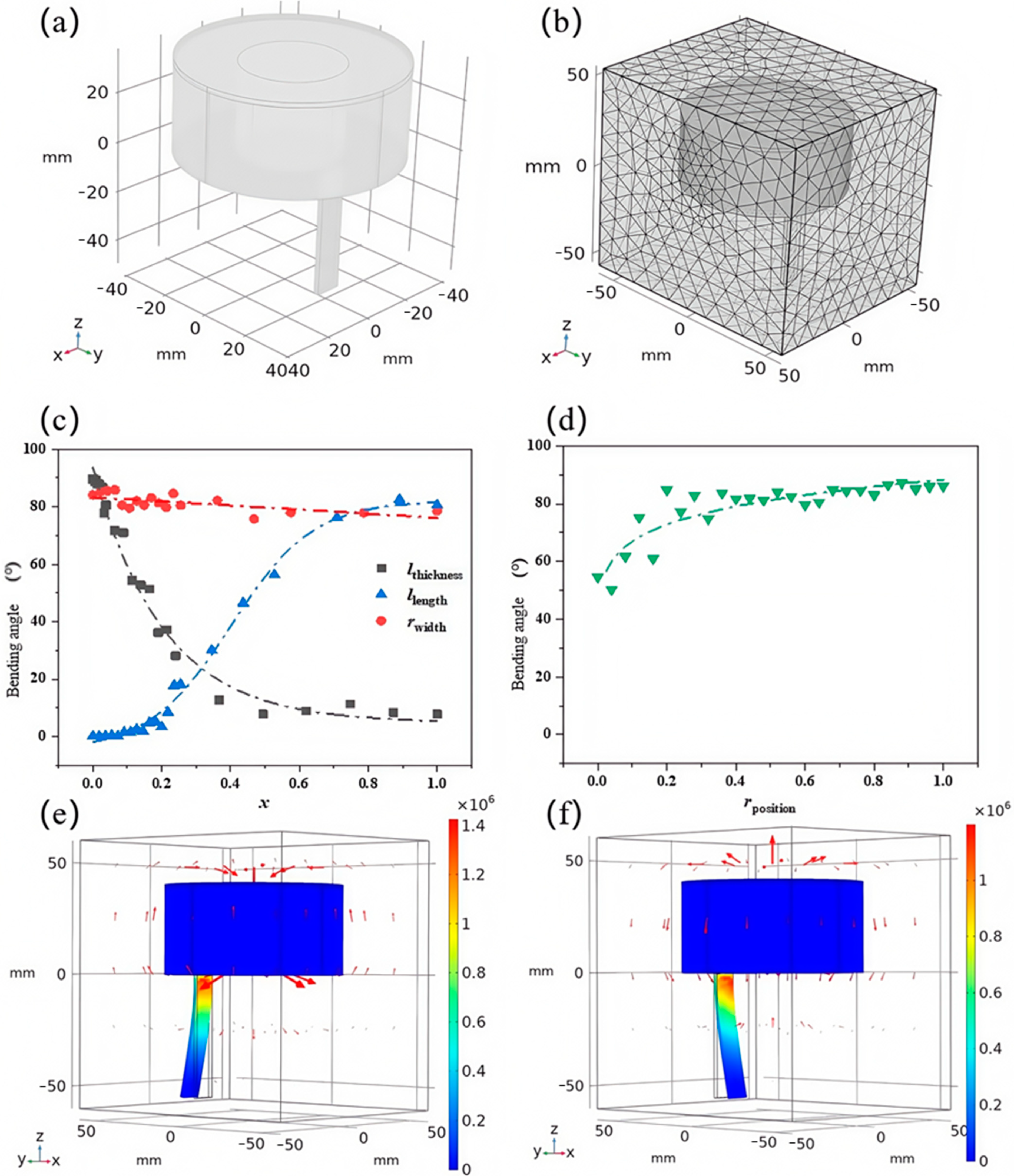
As illustrated in Figure 5a, due to the real symmetric structure of the flexible finger, only one finger is modeled, and a rectangular geometric air domain is established around the single-finger model to simulate the working environment in which the flexible gripper operates. The key parameters of the excitation device for the simulation are consistent with those in Table 1, while the additional key parameters required are detailed in Table 2.
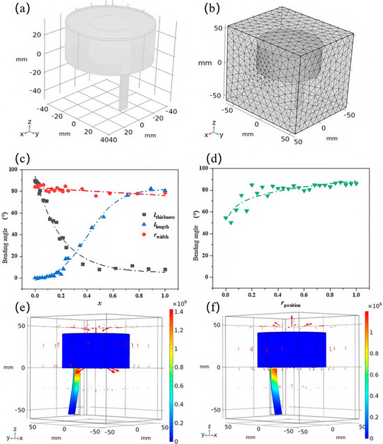
Figure 5.
Simulation modeling of fingers. (a) Modeling of a single finger of magnetically controlled bionic flexible gripper. (b) Simulation meshing. (c) Normalized width, length, and thickness versus bending angle. (d) Normalized reposition versus bending angle. (e) Effect of reverse magnetic field on bending. The arrow direction indicates the magnetic field direction, and the arrow length reflects the magnetic field strength. (f) Effect of forward magnetic field on bending.
Table 2.
Simulation key parameters of flexible fingers.
To investigate the effect of flexible finger size on magnetron performance, the dimensional parameters of the flexible finger are illustrated in Figure 2c. In the simulation, the control variable method was employed for the study. Based on the literature review, two of the three parameters , , and were fixed, while the remaining one was varied using a parametric scan in COMSOL Multiphysics 6.0 to compute the bending angle at the fingertip. Since , , and represent distinct physical properties, they were assigned different value ranges. Considering the integrated structure of the flexible finger and the excitation device, the size ranges of the flexible finger are constrained by the excitation device as follows: , , and . To eliminate the influence of value ranges on the results, all three parameters were normalized. The simulation results are presented in Figure 5c.
It is evident that the length (), width (), and thickness () of the flexible finger exhibit varying effects on the bending angle. Specifically, and significantly influence the bending angle, whereas has a comparatively minor effect. As increases, the bending angle of the flexible finger increases and eventually saturates at a certain length. Conversely, the bending angle decreases with increasing . Meanwhile, the bending angle shows only a slight decrease with increasing . In other words, within a specific range, a longer length and narrower width of the magnetically controlled flexible finger result in a larger bending angle. The width can be adjusted within a certain range according to practical applications without significantly affecting the gripping performance. However, the bending angle is not solely determined by the size of the flexible finger but is also influenced by its distance from the axis of the excitation device.
To investigate the effect of flexible finger position on the magnetron performance, simulations were performed in COMSOL Multiphysics 6.0 using parametric scanning to investigate the relationship between the distance of the flexible finger from the center of the axis () and the bending angle. The dimensions of the flexible fingers are used with the better-performing values from the results of Figure 5c, and the results are shown in Figure 5d. The simulation results are processed using normalization to eliminate the effect of magnitude. As can be seen, the flexible fingers need to be a certain distance from the axis to bend to ninety degrees. Too close a distance can seriously affect the bending angle, while the effect on the bending angle decreases as the distance increases. And increasing the distance between the flexible fingers and the axis of the excitation device not only produces a larger bending angle but also increases the upper size limit of the object to be gripped.
Figure 5e,f illustrate how the direction of the magnetic field influences the bending direction of the flexible finger. This directional change is directly attributable to alterations in the magnetic force’s orientation. In Figure 5e, the polarity of the excitation device is opposite to that of the flexible finger, resulting in a repulsive force that causes the finger to bend outward. Conversely, in Figure 5f, the matching polarities induce an attractive force, leading the flexible finger to bend inward.
These observations suggest that for objects exceeding the size accommodated by the naturally vertical lower end of the flexible gripper, a reversed magnetic field can be employed to spread the flexible fingers apart, followed by a forward magnetic field to contract the fingers and securely grasp the object. By synergizing adjustments in magnetic field direction with variations in magnetic field intensity, the upper limit of the gripping size of the flexible gripper can be significantly extended.
2.6. Effect of Filling Volume Ratio of NdFeB on Magnetization Performance
Although the effects of various macro-parameters on the magnetization performance of flexible fingers were investigated through simulation, certain micro-parameters, such as the volume ratio of NdFeB particles and surface roughness, require experimental investigation to fully understand their impact.
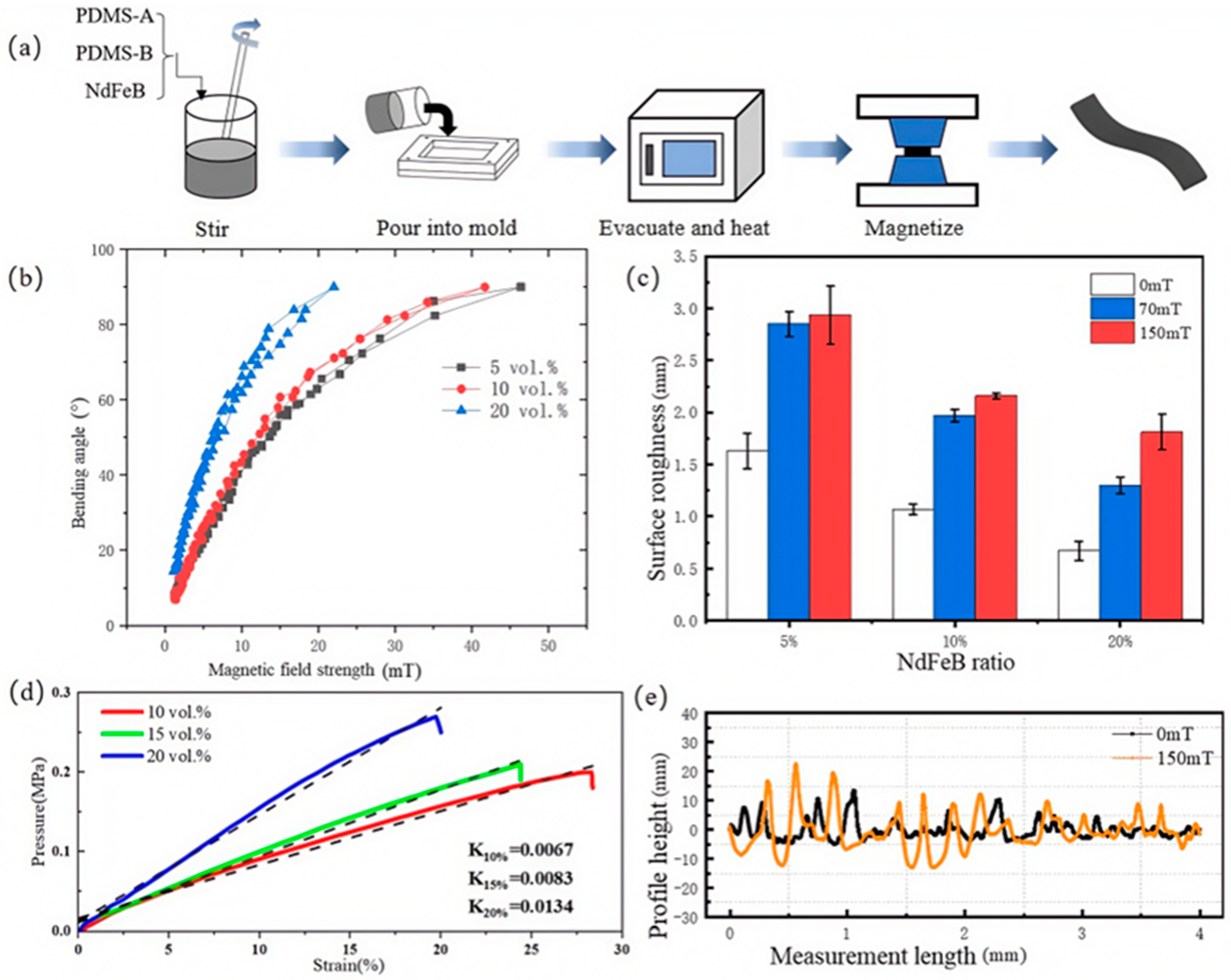
The flexible finger samples were fabricated using a matrix of Dow Corning Sylgard 184, a two-component silicone rubber (PDMS, model Sylgard 184, Manufactured by Dow Corning Corporation, Midland, MI, USA). The isotropic fast-quenching NdFeB rare-earth magnetic powders (model LW-N, manufactured by Guangzhou Xinbei Transmission Parts Co., Ltd., Shanghai, China) with particle sizes ranging from 40 m to 200 m. The sample fabrication process is illustrated schematically in Figure 6a.
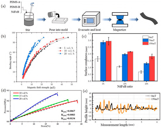
Figure 6.
Effect of filling volume ratio of NdFeB on magnetron performance. (a) Schematic diagram of the preparation of magnetically controlled bionic flexible gripper. (b) Magnetic field versus bending angle of flexible fingers with different NdFeB volume fractions. (c) Variation in surface roughness of flexible fingers under magnetic field. (d) Pressure–strain curves of flexible fingers with different NdFeB volume fractions. (e) Variation in the surface profile of samples with NdFeB volume fraction of 20%.
Initially, Component A (10 mass parts), Component B (1 mass part), and NdFeB (several mass parts) of PDMS were thoroughly mixed and introduced into a mold. The uncovered mold was then placed in a vacuum chamber to remove air bubbles. Subsequently, the mold was capped and transferred to a heating chamber, where it was cured at 80 °C for two hours. Finally, the cured samples were magnetized under an applied magnetic field, with the mass of NdFeB and the strength of the magnetic field adjusted according to experimental requirements.
To investigate the influence of the NdFeB volume fraction on the bending angle of flexible fingers, samples with volume fractions of 5%, 10%, and 20% were prepared. In this experiment, samples with a NdFeB volume fraction exceeding 20% were excluded primarily due to potential adverse effects from increasing the magnetic particle content further. These effects include significant increases in material rigidity, reductions in flexibility, and the onset of magnetic saturation. For example, Kim Y. et al. [34] and Zhao J. et al. [35] have noted that surpassing a critical threshold by enhancing the magnetic particle content can lead to increased material hardness, diminished flexibility, or magnetic saturation, all of which could ultimately impede overall performance improvements.
As shown in Figure 6d, we further evaluated the elastic modulus of NdFeB flexible fingers with different volume fractions (10%, 15%, and 20%) using a series of pressure–strain relationship curves. The sample with a 10% volume fraction exhibited an elastic modulus E10% = 0.0067, which allowed it to withstand relatively small pressure changes under low strain conditions. The sample with a 15% volume fraction demonstrated balanced stiffness and flexibility, with an elastic modulus E15% = 0.0083. Meanwhile, the sample with a 20% volume fraction had an elastic modulus E20% = 0.0134, enabling it to endure greater pressures under identical strain conditions while still maintaining moderate flexibility. These findings indicate that, when designing flexible fingers, a careful balance between stiffness and flexibility must be achieved.
The magnetization performance of these samples was sequentially evaluated using a custom-designed testing system. The experimental results, depicted in Figure 6b, reveal that the volume fraction significantly affects the magnetization performance. Specifically, the driving magnetic field—defined as the minimum magnetic field required to bend the flexible finger to 90°—decreases with increasing NdFeB volume fraction. The driving magnetic fields for samples with 5%, 10%, and 20% NdFeB were measured as 46.4 mT, 41.7 mT, and 22 mT, respectively. This indicates that higher NdFeB content reduces energy consumption during operation. Additionally, the linearity and repeatability of the bending angle variation were found to be excellent, suggesting that NdFeB-filled magnetic-sensitive rubber is well-suited for magnetically controlled flexible actuators.
Figure 6c illustrates the variation in surface roughness of flexible fingers with different NdFeB volume fractions under varying magnetic fields. The results indicate that the surface roughness increases with the applied magnetic field for all three volume fractions. Notably, the sample with a 20% NdFeB volume fraction exhibited the highest rate of change in surface roughness, reaching 170.15% under a 150 mT magnetic field. To further visualize these changes, the surface profiles of the 20% NdFeB sample under both magnetized (150 mT) and non-magnetized conditions are compared in Figure 6e. The non-magnetized sample displayed a relatively flat surface with fewer convex peaks and a smaller peak-to-valley difference. In contrast, under a 150 mT magnetic field, the surface became significantly more uneven, with increased convex peaks and a larger peak-to-valley difference. The maximum peak-to-valley difference increased from 13.60 m to 22.57 m, representing a 65.95% increase.
2.7. Machining and Assembly of Magnetically Controlled Bionic Flexible Grippers
The physical and model diagrams of each component are shown in Figure 7a–d.
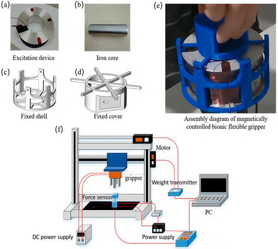
Figure 7.
Test method and platform construction of magnetically controlled bionic flexible gripper. (a) Magnetic control bionic flexible gripper parts excitation device. (b) The iron core of the magnetically controlled bionic flexible gripper. (c) Fixed housing for the parts of the magnetically controlled bionic flexible gripper. (d) Fixed cover of the parts of the magnetically controlled bionic flexible gripper. (e) Assembly diagram of the magnetically controlled bionic flexible gripper. (f) Schematic diagram of the test platform of the magnetically controlled bionic flexible gripper.
Three-dimensional-printed housing and top cover are used as connecting fixtures during fabrication. The coil’s backbone is machined from aluminum alloy, a material that meets the requirements for structural strength and magnetic conductivity in gripping tasks. The grooves on the skeleton reduce the overall weight on one hand and improve heat dissipation on the other. The copper wire has a 0.6 mm cross-sectional diameter and is a 200 °C fluorine-resistant enameled purple copper wire, with 900 turns wound. The actual number of wound turns may deviate from the theoretical calculation due to the neatness and density of the winding process. After completing the coil winding, the core is inserted into the hollow part of the coil, followed by the placing of the fixed shell and cover, thus completing the assembly of the excitation device. The completed assembly is shown in Figure 7e.
3. Results
3.1. Testing Method and Platform Construction of Magnetically Controlled Bionic Flexible Grippers
Researcher Y. Hao [36] demonstrated that the effective length of the pneumatic flexible gripper and the shape of the object being gripped significantly influence the maximum pull force, which determines the heaviest objects the gripper can handle. The maximum pull force is a critical performance metric for magnetically controlled bionic flexible grippers in practical applications. Therefore, it is essential to evaluate the gripping performance from these two perspectives and demonstrate the actual gripping effect. Given that research on magnetically controlled flexible grippers is still in its early stages and lacks a mature testing framework, this study designs a comprehensive test platform and methodology based on the required data and references the testing protocols for pneumatic flexible grippers. The hardware components of the test system primarily include a motion system, a magnetically controlled bionic flexible gripper, and a data acquisition system. The schematic of the test platform is illustrated in Figure 7f.
The motion system consists of a stepper motor and its control device. To meet the requirements for gripping force measurement during testing, a three-phase closed-loop servo stepper motor (model 573HBM20-1000, manufactured by Shenzhen Seray Intelligent Control Co., Ltd., Shenzhen, China) is employed as the power source. Since the experimental process necessitates precise control of motor movement and step count, a specialized stepper motor controller (model DKC-X200, manufactured by Shanghai Yibiao Automation Technology Co., Ltd., Shanghai, China) is utilized. This controller receives commands from the host computer and executes complex motor movements. For measuring the gripping force of the magnetically controlled bionic flexible gripper, a high-precision S-type force transducer (model AT8302, manufactured by Suzhou Ouluda Automation Equipment Co., Ltd., Suzhou, China) is selected. This sensor operates as a resistive strain sensor, capable of detecting both tensile and compressive forces within a range of 5 N. Due to the weak analog signal output of the force sensor, it is paired with a TDA-02 weight transmitter (manufactured by Suzhou Ouluda Automation Equipment Co., Ltd., Suzhou, China) for signal filtering and amplification before transmission to the data acquisition card. The YAV 8AD-24 8-channel 24-bit data sampling card (manufactured by Wuhan Yawei Technology Co., Ltd., Wuhan, China) is chosen for A/D conversion and data transmission. Following the design of each subsystem, the test platform is constructed according to the testing protocol for magnetically controlled bionic flexible grippers.
3.2. Gripping Force Study of Magnetically Controlled Bionic Flexible Gripper
3.2.1. Effect of Flexible Finger Length on Grasping Force
The graphs in Figure 8 depict various flexible finger lengths, represented by distinct lines. Each data point is derived from five tests, with outliers removed, and the average value is used as the final data point. As illustrated in the graphs, except for the 60 mm curves in Figure 8b,c, all curves exhibit a parabolic trend, indicating a peak in the tension of the flexible gripper. Additionally, the diameter of the orb corresponding to the peak tension increases with the length of the flexible finger. This suggests that the length of the flexible finger in the magnetically controlled bionic flexible gripper can be optimized based on the size of the object to be gripped, thereby enhancing the gripper’s operational range. This phenomenon may be attributed to the increased contact area between the flexible finger and the object when their sizes are similar, leading to greater friction, which significantly contributes to the gripping force.
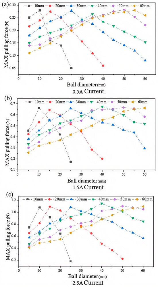
Figure 8.
Relationship between the length of the flexible finger, the diameter of the spherical grasped object, and the maximum pulling force. (a) The relationship between the length of the flexible finger, the diameter of the spherical grasped object, and the maximum tensile force at a current of 0.5 A. (b) The relationship between the length of the flexible finger, the diameter of the spherical grasped object, and the maximum tensile force at a current of 1.5 A. (c) The relationship between the length of the flexible finger, the diameter of the spherical grasped object, and the maximum tensile force under 2.5 A current.
By analyzing Figure 8a–c, it is evident that the peak tension force of the flexible gripper increases with the excitation current. Specifically, the gripping force triples when the excitation current is raised from 0.5 A to 2.5 A. Furthermore, neither the length of the flexible fingers nor the size of the grasped object affects the peak tensile force of the gripper, indicating that the peak tension force is solely dependent on the strength of the control magnetic field.
To facilitate a more intuitive comparison of magnetically controlled flexible grippers designed under different programs, the grasping energy efficiency is defined as the weight of the object that can be grasped per 1 mT of the magnetic field. Measurements using a Tesla meter reveal that the maximum magnetic field on the surface of the excitation device is approximately 210 mT at a current of 2.5 A. Consequently, the maximum grasping energy efficiency of the integrated magnetically controlled bionic flexible gripper designed in this study is calculated to be about 0.524 g/mT for a spherical object at 2.5 A.
3.2.2. A Study of the Effect of Shape and Handedness of Grasped Objects on Grasping Force
To investigate the effect of the shape of the object to be grasped and the number of flexible fingers on the grasping force of the flexible gripper, objects with different shapes but the same external sphere were printed using a 3D printing machine. The length of the flexible fingers (50 mm) and the magnitude of the excitation current (2.5 A) were fixed during testing. Each shape was tested five times, and the average value was taken after removing outliers and repeating the test. The test results are shown in Figure 9.

Figure 9.
Effect of the shape of the grasped object on the grasping force of a magnetically controlled bionic flexible gripper.
The results show that the shape of the object and the number of flexible fingers significantly impact the grasping force. The hollow ring exhibits the highest grasping force, followed by square shapes and their variants. Spheres and cylinders have intermediate levels of grasping force, while rectangular shapes demonstrate the lowest grasping force. The lower grasping force of rectangular objects may be due to their placement hindering the flexible fingers from adhering well to the bottom of the object, leading to insufficient support and making friction the dominant source of grasping force. In contrast, shapes with higher grasping forces allow the flexible fingers to extend properly and conform to the bottom of the object, providing substantial support, with friction contributing only a minor portion. Furthermore, both the four-finger and six-finger magnetically controlled bionic flexible grippers follow the same trend across different shapes, but the six-finger gripper generally exhibits greater grasping force. The efficiencies are 0.833 g/mT for the four-finger gripper and 1.21 g/mT for the six-finger gripper. This suggests that increasing the number of fingers can enhance the grasping force and optimizing the gripper design by adjusting the number of fingers can improve grasping efficiency.
Specifically, for the six-fingered magnetically controlled bionic flexible gripper, the total weight of the electromagnetic coil and the bionic fingers is 1075.1 g. Under the conditions of a 2.5 A current and a maximum magnetic field intensity of approximately 210 mT at the surface of the excitation device, its maximum gripping efficiency value is 1.21 g/mT, with a maximum gripping capacity of 254.1 g. These parameters further illustrate that the design of this gripper takes into account operational flexibility and energy consumption efficiency in practical applications while ensuring a certain level of gripping capability.
3.2.3. Grasping Adaptation Experiments with Grippers
The grasping process is illustrated in Figure 10. To validate the adaptability and practical effectiveness of the magnetically controlled bionic flexible gripper, this paper demonstrates the process of grasping various living objects. The figure succinctly illustrates how the gripper handles different items, with all grasps being switch-controlled. Each row in the figure represents a complete attempt to grasp an object. The first column shows the preparation phase of the flexible gripper, the second column depicts the gripper being energized to perform the grasping action, and the third column illustrates the gripper lifting the object.
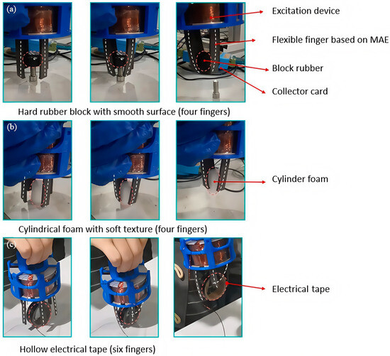
Figure 10.
Integrated magnetically controlled bionic flexible gripper for gripping household objects, the white dashed line represents the outline of the flexible finger. (a) Gripping hard rubber blocks with smooth surfaces. (b) Gripping soft cylindrical foam. (c) Gripping hollow electrical tape.
Figure 10a shows the gripper capturing a smooth-surfaced black rubber cylinder with a mass of 10.51 g, a diameter of 28 mm, and a height of 9 mm, under a controlled magnetic field of 73 mT. Figure 10b illustrates the successful grasping of a soft foam cylinder, demonstrating that the flexible gripper can adapt well to the shape of the object, ensuring both safety and effectiveness. Additionally, the data acquisition cards function normally during the gripping process, indicating that the gripper is safe for other components in the working environment.
Figure 10c depicts the process of the gripper grasping an electric tape with a hollow shape. Combining observations from Figure 10a–c, it is evident that the integrated magnetically controlled bionic flexible gripper not only allows for flexible adjustment of the number of fingers but also adapts effectively to objects of various shapes, ensuring the safety of both the object and other components in the work environment. These attributes are attributed to the integrated structural design of the bionic hand.
4. Conclusions
In this study, to address the safety and gripping force issues of magnetically controlled flexible grippers, a novel structure inspired by the human hand was designed, integrating an excitation device with magnetically controlled flexible fingers. Using COMSOL Multiphysics 6.0 simulations, it was found that the magnetic field strength peaks when the core-to-coil size ratio is 1:5. Further research revealed that magnetically sensitive rubber containing 20% NdFeB particles, compared to those with 5% and 10% NdFeB, exhibited superior bending performance, capable of bending 90° under just 22 mT of magnetic field. However, it should be noted that NdFeB content exceeding 20% was not considered in the experiments, and further exploration of the optimal volume fraction ratio of NdFeB will be needed in future experiments. The optimized excitation device significantly enhanced grasping performance; the finger length matched well with the object size, and the grasping force increased with both magnetic field strength and the number of fingers. The four-finger flexible gripper developed in this study achieved a gripping efficiency of 0.625 g/mT, offering a new approach to designing and optimizing magnetically controlled flexible grippers. Future research will explore adding angle self-feedback functionality to the flexible gripper.
Author Contributions
Conceptualization, P.Y.; data curation, Y.D. and M.S.; formal analysis, Y.D.; funding acquisition, P.Y.; investigation, P.Y. and X.B.; methodology, X.B. and P.Y.; project administration, X.B.; software, Y.D.; validation, R.L.; visualization, X.B.; writing—original draft, X.B. and Y.D.; writing—review and editing, P.Y. and R.L. All authors have read and agreed to the published version of the manuscript.
Funding
This work was supported by the Science and Technology Research Program of Chongqing Mu-nicipal Education Commission (Grant No. KJZD-K202300606), Chongqing Municipal Natural Science Foundation (Grant No. CSTB2022NSCQ-MSX0380), National High-end Foreign Experts Introduction Plan (Grant No. G2022035005L), and Chongqing Talent Plan of Overall Rationing System Project (no. CQYC202203091156).
Data Availability Statement
The data supporting the findings of this manuscript are available from the corresponding authors upon reasonable request.
Conflicts of Interest
The authors declare no conflict of interest.
References
- Chua, P.Y.; Ilschner, T.; Caldwell, D.G. Robotic manipulation of food products—A review. Ind. Robot 2003, 30, 345–354. [Google Scholar] [CrossRef]
- Sitti, M.; Ceylan, H.; Hu, W.; Giltinan, J.; Turan, M.; Yim, S.; Diller, E. Biomedical applications of untethered mobile milli/microrobots. Proc. IEEE 2015, 103, 205–224. [Google Scholar] [CrossRef]
- Hughes, J.; Culha, U.; Giardina, F.; Guenther, F.; Rosendo, A.; Iida, F. Soft manipulators and grippers: A review. Front. Robot. AI 2016, 3, 69. [Google Scholar]
- Zhang, J.; Pang, H.; Wang, Y.; Gong, X. The magneto-mechanical properties of off-axis anisotropic magnetorheological elastomers. Compos. Sci. Technol. 2020, 191, 108079. [Google Scholar] [CrossRef]
- Shintake, J.; Cacucciolo, V.; Floreano, D.; Shea, H. Soft Robotic Grippers. Adv. Mater. 2018, 30, 1707035. [Google Scholar] [CrossRef] [PubMed]
- Martinez, R.V.; Branch, J.L.; Fish, C.R.; Jin, L.; Shepherd, R.F.; Nunes, R.; Whitesides, G.M. Robotic Tentacles with Three-Dimensional Mobility Based on Flexible Elastomers. Adv. Mater. 2013, 25, 205–212. [Google Scholar] [CrossRef]
- Martinez, R.V.; Fish, C.R.; Chen, X.; Whitesides, G.M. Elastomeric Origami: Programmable Paper-Elastomer Composites as Pneumatic Actuators. Adv. Funct. Mater. 2012, 22, 1376–1384. [Google Scholar] [CrossRef]
- Yap, H.K.; Ng, H.Y.; Yeow, C. High-Force Soft Printable Pneumatics for Soft Robotic Applications. Soft Rob. 2016, 3, 144–158. [Google Scholar] [CrossRef]
- Robertson, M.A.; Sadeghi, H.; Florez, J.M.; Paik, J. Soft Pneumatic Actuator Fascicles for High Force and Reliability. Soft Rob. 2017, 4, 23–32. [Google Scholar] [CrossRef]
- Pelrine, R.; Kornbluh, R.; Pei, Q.; Joseph, J. High-Speed Electrically Actuated Elastomers with Strain Greater Than 100%. Science 2000, 287, 836–839. [Google Scholar] [CrossRef]
- Pelrine, R.; Kornbluh, R.; Kofod, G. High-Strain Actuator Materials Based on Dielectric Elastomers. Adv. Mater. 2000, 12, 1223–1225. [Google Scholar] [CrossRef]
- Duduta, M.; Wood, R.J.; Clarke, D.R. Multilayer Dielectric Elastomers for Fast, Programmable Actuation without Prestretch. Adv. Mater. 2016, 28, 8058–8063. [Google Scholar] [CrossRef] [PubMed]
- Lau, G.; Heng, K.; Ahmed, A.S.; Shrestha, M. Dielectric elastomer fingers for versatile grasping and nimble pinching. Appl. Phys. Lett. 2017, 110, 182906. [Google Scholar] [CrossRef]
- Simone, F.; Rizzello, G.; Seelecke, S. Metal muscles and nerves—A self-sensing SMA-actuated hand concept. Smart Mater. Struct. 2017, 26, 95007. [Google Scholar] [CrossRef]
- Ge, Q.; Sakhaei, A.H.; Lee, H.; Dunn, C.K.; Fang, N.X.; Dunn, M.L. Multimaterial 4D Printing with Tailorable Shape Memory Polymers. Sci. Rep. 2016, 6, 31110. [Google Scholar] [CrossRef]
- Villanueva, A.; Smith, C.; Priya, S. A biomimetic robotic jellyfish (Robojelly) actuated by shape memory alloy composite actuators. Bioinspir. Biomim. 2011, 6, 36004. [Google Scholar] [CrossRef]
- She, Y.; Chen, J.; Shi, H.; Su, H.J. Modeling and Validation of a Novel Bending Actuator for Soft Robotics Applications. Soft Rob. 2016, 3, 71–81. [Google Scholar] [CrossRef]
- Kim, H.I.; Han, M.W.; Song, S.H.; Ahn, S.H. Soft morphing hand driven by SMA tendon wire. Compos. Part B 2016, 105, 138–148. [Google Scholar] [CrossRef]
- Mohd Jani, J.; Leary, M.; Subic, A.; Gibson, M.A. A review of shape memory alloy research, applications and opportunities. Mater. Des. 2014, 56, 1078–1113. [Google Scholar] [CrossRef]
- Kim, J.; Chung, S.E.; Choi, S.-E.; Lee, H.; Kim, J.; Kwon, S. Programming magnetic anisotropy in polymeric microactuators. Nat. Mater. 2011, 10, 747–752. [Google Scholar] [CrossRef]
- Nguyen, V.Q.; Ahmed, A.S.; Ramanujan, R.V. Morphing soft magnetic composites. Adv. Mater. 2012, 24, 4041–4054. [Google Scholar] [CrossRef] [PubMed]
- Kim, Y.; Yuk, H.; Zhao, R.; Chester, S.A.; Zhao, X. Printing ferromagnetic domains for untethered fast-transforming soft materials. Nature 2018, 558, 274–279. [Google Scholar] [CrossRef]
- Qi, S.; Guo, H.; Fu, J.; Xie, Y.; Zhu, M.; Yu, M. 3D printed shape-programmable magneto-active soft matter for biomimetic applications. Compos. Sci. Technol. 2020, 188, 107973. [Google Scholar] [CrossRef]
- Gao, W.; Wang, L.; Wang, X.; Liu, H. Magnetic driving flowerlike soft platform: Biomimetic fabrication and external regulation. ACS Appl. Mater. Interfaces 2016, 8, 14182–14189. [Google Scholar] [CrossRef]
- Li, M.; Wang, Y.; Chen, A.; Naidu, A.; Napier, B.S.; Li, W.; Rodriguez, C.L.; Crooker, S.A.; Omenetto, F.G. Flexible magnetic composites for light-controlled actuation and interfaces. Proc. Natl. Acad. Sci. USA 2018, 115, 8119–8124. [Google Scholar] [CrossRef] [PubMed]
- Lee, D.; Lee, M.; Jung, N.; Yun, M.; Lee, J.; Thundat, T.; Jeon, S. Modulus-tunable magnetorheological elastomer microcantilevers. Smart Mater. Struct. 2014, 23, 055017. [Google Scholar] [CrossRef]
- Gong, X.; Zhang, X.; Zhang, P. Fabrication and characterization of isotropic magnetorheological elastomers. Polym. Test. 2005, 24, 669–676. [Google Scholar] [CrossRef]
- Hatch, G.P.; Stelter, R.E. Magnetic design considerations for devices and particles used for biological high-gradient magnetic separation (HGMS) systems. J. Magn. Magn. Mater. 2001, 225, 262–276. [Google Scholar] [CrossRef]
- Davis, L. Model of magnetorheological elastomers. J. Appl. Phys. 1999, 85, 3348–3351. [Google Scholar] [CrossRef]
- Zheng, X.-J.; Wang, X. Analysis of magnetoelastic interaction of rectangular ferromagnetic plates with nonlinear magnetization. Int. J. Solids Struct. 2001, 38, 8641–8652. [Google Scholar] [CrossRef]
- Naimzad, A.; Ghodsi, M.; Hojjat, Y.; Maddah, A. MREs development and its application on miniature gripper. In Proceedings of the 2011 International Conference on Advanced Materials Engineering, Suntec, Singapore, 26 June–1 July 2011; pp. 75–80. [Google Scholar]
- Li, R.; Ren, D.; Wang, X.; Chen, X.; Chen, S.; Wu, X. Tunable friction performance of magneto-rheological elastomer induced by external magnetic field. J. Intell. Mater. Syst. Struct. 2018, 29, 160–170. [Google Scholar] [CrossRef]
- Li, R.; Li, X.; Yang, P.-a.; Liu, J.; Chen, S. The field-dependent surface roughness of magnetorheological elastomer: Numerical simulation and experimental verification. Smart Mater. Struct. 2019, 28, 085018. [Google Scholar] [CrossRef]
- Kim, Y.; Parada, G.A.; Liu, S.; Zhao, X. Ferromagnetic soft continuum robots. Sci. Rob. 2019, 4, eaax7329. [Google Scholar] [CrossRef] [PubMed]
- Zhao, J.; Li, X.; Tan, Y.; Liu, X.; Lu, T.; Shi, M. Smart adhesives via magnetic actuation. Adv. Mater. 2022, 34, 2107748. [Google Scholar] [CrossRef]
- Hao, Y.; Gong, Z.; Xie, Z.; Guan, S.; Yang, X.; Ren, Z.; Wang, T.; Wen, L. Universal soft pneumatic robotic gripper with variable effective length. In Proceedings of the 2016 35th Chinese control conference (CCC), Chengdu, China, 27–29 July 2016; pp. 6109–6114. [Google Scholar]


Disclaimer/Publisher’s Note: The statements, opinions and data contained in all publications are solely those of the individual author(s) and contributor(s) and not of MDPI and/or the editor(s). MDPI and/or the editor(s) disclaim responsibility for any injury to people or property resulting from any ideas, methods, instructions or products referred to in the content. |
© 2025 by the authors. Licensee MDPI, Basel, Switzerland. This article is an open access article distributed under the terms and conditions of the Creative Commons Attribution (CC BY) license (https://creativecommons.org/licenses/by/4.0/).