Abstract
To address the mismatch between materials and operational speed in mine scraper conveyors under time-varying load conditions, this paper proposes a methodology for the regulation of speed based on the quantity of coal transported by the scraper conveyor. Furthermore, a vector control strategy for permanent magnet synchronous motors (PMSMs) is presented, underpinned by a global fast terminal sliding mode controller. Firstly, a calculation model for the real-time coal volume of the scraper conveyor was developed based on the double-end oblique cutting coal mining technology in fully mechanized mining operations. This model takes into account the operational condition of the shearer and the scraper conveyor. In addition, a graded speed regulation control method was introduced. Secondly, a global fast terminal controller was developed by integrating the features of linear and terminal sliding mode surfaces. An enhanced sliding mode vector control strategy for the permanent magnet drive motor of the scraper conveyor was subsequently proposed. Finally, a simulation and ground test were subsequently performed on the PMSM experimental bench and SGZ2×1200 scraper conveyor to validate the proposed control strategy. The results indicated that the proposed control strategy not only diminished the overshoot of the rotational speed and decreased the dynamic response time but also improved the anti-interference capabilities of the PMSM relative to the original PI control. Moreover, the ground test validated the feasibility of the suggested speed regulation method.
1. Introduction
Integrated mechanized coal mining technology is currently the most prevalent mining technology in coal mines. It encompasses a range of mechanized operational links within the coal mining system, including support, coal mining, loading, transportation, and working face advancement. It is currently the most efficient shaft mining technology [1,2,3]. Integrated mining technology comprises three main supporting equipment components: a coal mining machine, a scraper conveyor, and a hydraulic support [4,5]. The scraper conveyor plays a pivotal role in the integrated mining transport system. In addition to loading and transporting coal, it also serves as the track for the coal mining machine and the pivot point for the hydraulic support. The efficient and stable operation of the scraper conveyor significantly impacts the production capacity and economic benefits of the coal mine [6,7,8,9].
Permanent magnet drive scraper conveyors adopt permanent magnet synchronous motors (PMSMs) as their power source to replace the asynchronous motor in the traditional drive system. A PMSM is a kind of motor using permanent magnet excitation; no excitation winding is needed in the rotor structure, which has the significant advantages of a simple structure, high efficiency, low energy consumption, and so on, compared with traditional asynchronous motors [10,11,12]. Permanent magnet drive technology is a kind of green, efficient, and intelligent drive technology using a PMSM to drive loads, which is currently a research hotspot in the field of permanent magnet equipment control in coal mines due to its advantages of a wide speed regulation range, good torque characteristics, and fast dynamic response [13,14,15].
In the context of underground coal mining, the operational challenges faced by scraper conveyors are often attributed to the intricate geological environment and suboptimal working conditions [16]. These challenges, which include coal wall flake gangs, scraper jamming, and coal block falling, have the potential to generate significant impacts and vibrations on the chain drive system and motor drive system. Consequently, these impacts can affect the stable operation of the equipment. Furthermore, the cutting efficiency of a coal mining machine is also influenced by geological conditions and the structure of the coal seam. When the traction speed, cutting drum rotation speed, and running direction of the machine change, the amount of coal extracted also changes. As a consequence, the amount of coal loaded on the scraper conveyor is subject to constant variation throughout the transportation process [17,18]. It is therefore imperative to investigate a speed regulation method based on the actual loading capacity of the scraper conveyor in order to achieve an optimal matching between the material and the running speed. Furthermore, a suitable drive system control strategy should be proposed in accordance with the operational conditions and characteristics of the scraper conveyor, with the objective of mitigating the impact of load disturbances on the drive system. This is of great significance in order to ensure the safe and stable operation of the scraper conveyor, improve the transport efficiency of the working face, and reduce the energy consumption of comprehensive mining.
Currently, many scholars have conducted relevant research on the computation of running resistance for scraper conveyors, the dynamic characteristics of chain drive systems, and speed control methods. Wang et al. [19] employed the discrete element method to simulate the bulk coal conveying process using a scraper conveyor. They analyzed the variations in coal flow and chain speed as well as wear depth with respect to chain speed. These findings serve as a foundation for enhancing the conveying efficiency of scraper conveyors and determining appropriate operating speeds. The research results also offer guidance for analyzing and calculating running resistance at different speeds. Jiang et al. [20] set up a test bench for the scraper conveyor chain drive system and studied the dynamic characteristics of the chain drive system, which affect the efficiency of coal transport in the comprehensive mining face. The effects of different chain speeds, different loads, and different impact heights on the dynamic characteristics of the scraper conveyor chain drive system were analyzed under no-load and load conditions, and the changing law of the dynamic characteristics under different working conditions was obtained. Zheng et al. [21] analyzed and calculated the cutting resistance and traction resistance during one production cycle of unidirectional coal cutting for a shearer and established a model for calculating the energy consumption of a shearer, which derived the relationship between mining energy consumption and production, traction speed, and drum rotation speed, as well as effective coal mining time. The study also provided research ideas and methodological references for analyzing the coal loading capacity and calculating the operating resistance of a scraper conveyor in combination with the operating state of a shearer. Wang et al. [22] designed a coordinated speed regulation planning strategy between the shearer and scraper conveyor based on the load fluctuation of scraper conveyors, which was used to improve the stable operation ability of the scraper conveyor under complex working conditions and to avoid the effects of load fluctuation on the continuous production of integrated mining equipment, such as frequent breakdowns and shutdowns. The coordinated speed control system can reduce the coal stacking phenomenon of scraper conveyors to a certain extent and prevent the equipment from being in an overloaded operation state for a long time. Ma et al. [23] built a test platform for scraper conveyors and studied the rigid–discrete coupling effect of scraper conveyors under different chain speeds and load conditions through transport tests, revealing the motion law and force situation between coal and chain and scraper and bottom plate during transport and analyzing the mechanical and friction characteristics between different chain speeds and the central trough. The article also points out that long-term overloading and light-load operating conditions will adversely affect the relevant structure of the scraper conveyor, resulting in the reduced reliability and service life of the equipment, that the speed of the equipment should be adjusted according to the changes in load conditions, and that the frequency conversion speed control makes it possible to match the speed and load.
In order to reduce the influence of external disturbances on the control system, numerous scholars have investigated PMSM anti-disturbance control methods. Among them, sliding mode control has been widely used in permanent magnet synchronous motor control methods because of its advantages of having no need for an accurate mathematical model, a simple structure, an insensitivity to external disturbances and motor parameters, etc. [24,25,26]. To address the issues of slow convergence rates and jitter in traditional sliding mode control, Li et al. [27] proposed a nonlinear sliding mode control method combining a nonlinear convergence law with an expanded state observer, which could further improve the control system by compensating for the observed external disturbances to the speed controller through the introduction of an expanded state observer. The introduced extended state observer could compensate for the observed external disturbances to the speed controller to further improve the anti-interference capability of the control system. The performance of the proposed controller was numerically simulated on an experimental bench. Xu et al. [28] presented a composite sliding mode control strategy combining fast terminal sliding mode control and an adaptive extended state observer for the internal and external disturbances encountered in the actual operation of PMSM systems. Based on the fast terminal sliding mode control method, the system parameter variations and external disturbances were considered as aggregate disturbances and the designed adaptive extended state observer observed the aggregate disturbances and compensated the input signals. Chen et al. [29] proposed a speed control method for PMSM drives based on a continuous adaptive fast terminal sliding mode. The method improved the convergence law of continuous fast terminal sliding mode speed control based on the traditional sliding mode control strategy, which improves the system response speed and reduces the steady-state error. Secondly, a Luenberger disturbance observer was designed to estimate the total disturbance of the system and perform feedforward compensation. The composite control strategy achieved good start-up performance and control robustness of the PMSM speed control system.
Permanent magnet frequency conversion drive technology, which employs a PMSM as its power source, exhibits a distinctive attribute: low-speed output with a high torque. This quality renders it particularly well-suited to the requirements of the low-speed and heavy-duty drives in coal mining equipment [30,31]. In recent years, notable advancements have been made in the fields of coal mining, transport, and hoisting. Sheng et al. [32] proposed a shearer control system with a low-speed and large-torque PMSM as the drive source and established a mathematical model for the variation in cutting load between the PMSM and the coal mining machine. In accordance with the tenets of sliding mode control, a sensor-less control strategy founded upon a sliding mode observer was devised, and a fuzzy adaptive control algorithm was incorporated to regulate the switching gain. The simulation outcomes demonstrated that the novel control strategy exerted a salutary influence on the permanent magnet drive system of a shearer. Song et al. [33] conducted an investigation into a novel low-speed, large-torque permanent magnet direct-drive synchronous motor for use in belt conveyance. This motor exhibited advantageous characteristics, including a straightforward structure and high efficiency, when compared to existing asynchronous motor drive systems. The article undertook a comprehensive investigation of the key issues inherent to the motor design process, subsequently fabricating a prototype of the machine in question. The results of the tests and experiments demonstrated that this permanent magnet synchronous motor was capable of achieving complete direct drive of the conveyor. Additionally, the motor exhibited a reasonable outer rotor magnetic field design, a highly efficient cooling system, and good mechanical strength, thereby enhancing the operating performance of the belt conveyor. Lu et al. [34] proposed an efficient anti-interference speed control method for low-speed and large-torque permanent magnet synchronous motors to address the speed fluctuation problem of permanent magnet direct-drive scraper conveyors in mining due to complex working conditions. The method was designed based on a double-closed-loop vector control strategy, and the load disturbance was observed and feedforward compensated to the input of the current controller by the designed sliding mode observer in order to enhance the anti-interference capability of the control system. It was verified through simulation and experiments that the composite control scheme of the low-speed large-torque permanent magnet drive system had strong robustness and improved the dynamic response capability of the control system. Zhang et al. [35] took the chain drive system of a scraper conveyor driven by a PMSM as their research object, put forward a kind of electromechanical joint simulation model of the permanent magnet drive system and transmission system, and analyzed the change rule of the PMSM speed, scraper conveyor circular chain, and contact force of the sprocket and circular chain under three typical working conditions of no-load, half-load, and rated load. The simulation results indicated that the scraper conveyor powered by the PMSM could fulfill operational requirements across various working conditions, thereby offering insights into the advancement of permanent magnet drive technology in mining scraper conveyors.
As demonstrated in the aforementioned literature, the research methodologies utilized in the context of the running resistance of scraper conveyor systems often involve static or quasi-static assumptions, thereby neglecting the importance of real-time and dynamic factors. A similar issue arises in research on load identification and speed control for scraper conveyors, which rely on the measurement and analysis of motor current, voltage, power, and other parameters. This leads to limitations in the reliability of load identification and the precision of speed control. Furthermore, it is important to note that research on permanent magnet drive control technology for mine scraper conveyors is a relatively recent field, with limited exploration to date. The research on permanent magnet drive systems and speed regulation methods of scraper conveyors is of great significance.
Given this, this paper focuses on high-power mining scraper conveyors as its subject of investigation, with an emphasis on the regulation of conveyor speed and the control strategy of the permanent magnet drive system. The main contributions of this paper are as follows.
(1) The coal quantity calculation model of the scraper conveyor proposed in this paper combines the coal mining process flow of the fully mechanized mining face and comprehensively considers parameters such as the operating speed, cutting depth, coal cutting height, and position of the shearer. On this basis, a graded speed regulation scheme for the scraper conveyor was designed according to the corresponding relationship between the coal loading and the chain speed.
(2) This paper presents a design for a PMSM drive system with an integrated reduction device and frequency converter. In addition, a PMSM control strategy based on an improved sliding mode controller was proposed as a means of enhancing the stability of the speed control of the drive system.
The rest of the paper is organized as follows. In Section 2, the calculation method of coal loading and running resistance of the scraper conveyor based on the operating state of the shearer is analyzed in combination with the coal mining process flow, and the corresponding speed regulation scheme is given. In Section 3, the permanent magnet drive scheme is proposed, and the sliding mode speed controller of the PMSM is designed in combination with the vector control strategy. In Section 4, simulation and experimental results of the scraper conveyor permanent magnet drive system are given. The final section presents a brief summary of the study.
2. The Load Analysis and Speed Control Method Design of the Scraper Conveyor
In the design of a three-machine matching system for a comprehensive mining face, the rated load of the scraper conveyor is typically determined by the theoretically calculated maximum load. Furthermore, the calculation of operating resistance is based on the maximum operating resistance under ideal working conditions, without considering the actual comprehensive mining process. In practice, the coal load of the scraper conveyor is subject to change in accordance with the traction speed, position, and running direction of the shearer, as well as other parameters. Consequently, the calculation of its load and running resistance must be considered in conjunction with the characteristics of the working face, the coal mining process, and the operation of the dual machine.
At present, the vast majority of scraper conveyors maintain rated chain speeds during operation. When coal loading undergoes significant changes, an effective method is needed to adjust motor speed according to load, ensuring the scraper conveyor’s load remains within a reasonable range. Simultaneously, mechanical impacts caused by frequent speed adjustments must be avoided to prevent affecting equipment service life while ensuring optimal load state operation.
2.1. Coal Mining Process
The integrated mechanized coal mining process, which is currently widely used in coal mines, requires the coordinated operation and mutual cooperation of the shearer, hydraulic support, and scraper conveyor. The integrated mining face three-machine operations are shown in Figure 1. The shearer runs from the end of the upper groove diagonally cut into the seam to start cutting coal. It runs to the end of the down groove to adjust the roller’s position and then cuts again toward the end of the upper groove. This cyclic process allows the entire working face to be mined.
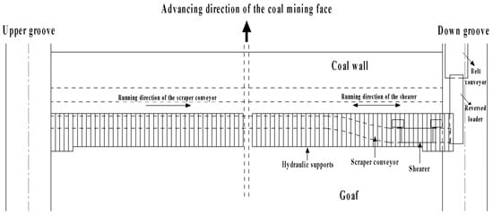
Figure 1.
Diagram of coordinated operation of three machines on mining face.
The quantity of coal transported by the scraper conveyor is contingent upon the operational status of the shearer. It is thus necessary to analyze the coal cutting process of the shearer prior to calculating the quantity of coal conveyed by the scraper conveyor. The reciprocating operation of the shearer on the working face can be divided into two distinct phases: the upper chute to lower chute and the lower chute to upper chute. As shown in Figure 2 and Figure 3, this paper employs the two-way cutting process of the end oblique cutter of the fully mechanized working face as a case study, selecting one cutting cycle of the coal cutter to analyze the coal load of the scraper conveyor.
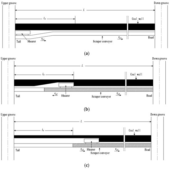
Figure 2.
The working processes of the shearer, cutting coal from the upper groove to the down groove: (a) process 1; (b) process 2; (c) process 3.
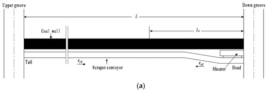
Figure 3.
The working processes of the shearer, cutting coal from the down groove to the upper groove: (a) process 4; (b) process 5; (c) process 6.
The coal cutting process of the shearer along the upper groove to the down groove is divided into three stages, as shown in Figure 2. Process 1 refers to the shearer’s oblique cutting and feeding at the end of the upper groove. The shearer starts to cut coal at the tail of the scraper conveyor; the oblique cutting starts at the bending section of the scraper conveyor; and the entirety of process 1 is concluded at the straight section of the scraper conveyor. In this process, the shearer runs at vs1 and the scraper conveyor runs at vc1. After this stage ends, the shearer is located at the completion of the feed, and the running distance is Ls.
Process 2 refers to the stage of back-cutting. At this point, the shearer alters the position of the double drum, adjusting it to a front-low, back-high state. Subsequently, the shearer cuts coal to the end of the upper groove. During this process, the speed of the shearer is vs2 and the chain speed of the scraper conveyor is vc2. At the end of this stage, the shearer is located at the end of the upper groove and the running distance is Ls.
Process 3 refers to the linear cutting stage of the shearer. The double drums of the shearer are in the states of high-front and low-back. Firstly, the float coal in the end triangular coal area is cleared, and then the full-speed coal cutting process commences at Ls. During this process, the hydraulic supports lag behind the shearer by a certain distance for frame moving and scraper conveyor pushing. The operating speed of the shearer is vs3, and the chain speed of the scraper conveyor is vc3. At the end of this stage, the shearer is situated at the terminus of the down groove, with a running distance of L. Concurrently, the position of the double drums is altered, and the next cutting of the shearer is awaited.
The coal cutting process of the shearer along the upper groove to the down groove is also divided into three stages, as shown in Figure 3. Process 4 is the shearer’s oblique cutting and feeding at the end of the down groove. The shearer starts to cut coal at the head of the scraper conveyor; the oblique cutting starts at the bending section of the scraper conveyor; and the entirety of process 4 is concluded at the straight section of the scraper conveyor. In this process, the shearer runs at vs4 and the scraper conveyor at vc4. After the end of this stage, the shearer is located at the completion of the feed, and the running distance is Ls.
Process 5 refers to the stage of back-cutting. Firstly, the shearer alters the position of the double drum, adjusting it to a front-high, back-low state. Subsequently, the shearer cuts coal to the end of the down groove. During this process, the speed of the shearer is vs5, and the chain speed of the scraper conveyor is vc5. At the end of this stage, the shearer is located at the end of the down groove and the running distance is Ls.
Process 6 refers to the linear cutting stage of the shearer. The double drums of the shearer are in the states of back-front and front-back. Firstly, the float coal in the end triangular coal area is cleared, and then the full-speed coal cutting process commences at Ls. During this process, the hydraulic supports lag behind the shearer by a certain distance for frame moving and scraper conveyor pushing. The operating speed of the shearer is vs6, and the chain speed of the scraper conveyor is vc6. At the end of this stage, the shearer is situated at the terminus of the upper groove, with a running distance of L.
2.2. Coal Quantity Calculation Model and Running Resistance of Scraper Conveyor
2.2.1. Coal Quantity Calculation Model
The mass of the coal cutting per meter length of the shearer qs can be obtained as follows:
where h is the mining height of the shearer, s is the cutting depth of the coal cutter, γ is the coal density, and c is the recovery rate of the fully mechanized working face.
If it is assumed that tis and tie represent the start and end times of process i of coal cutting, ts is the running time of the shearer, and txi is the start time of process i scraper conveyor unloading coal, then the coal mining quantity qsi of process i can be expressed as follows:
Considering the coal cutting process depicted in Figure 2 and Figure 3, it can be concluded that the mass of coal per meter length ρzi and the real-time coal quantity qzi of the scraper conveyor can be expressed, respectively, as follows:
(1) Process 1
After process 1, the shearer’s oblique cutting and feeding, is completed, the remaining coal quantity of the scraper conveyor can be expressed as follows:
(2) Process 2
After process 2, the shearer’ back-cutting, is completed, the remaining coal quantity on the scraper conveyor can be expressed as follows:
(3) Process 3
After process 3, the shearer’s linear cutting, is completed, the remaining coal quantity on the scraper conveyor can be expressed as follows:
(4) Process 4
After process 4, the shearer’s oblique cutting and feeding, is completed, the remaining coal quantity on the scraper conveyor can be expressed as follows:
(5) Process 5
After process 5, the shearer’s back-cutting, is completed, the remaining coal quantity on the scraper conveyor can be expressed as follows:
(6) Process 6
After process 6, the shearer’s linear cutting, is completed, the remaining coal quantity on the scraper conveyor can be expressed as follows:
2.2.2. Calculation of Running Resistance
The running resistance Fzi of the scraper conveyor on the loaded side during process i can be expressed as follows:
The running resistance Fki of the scraper conveyor on the unloaded side during process i can be expressed as follows:
where ρzi is the mass of coal per meter length of the scraper conveyor in process i, Lzi is the length from the shearer to the scraper conveyor head in process i, ρ2 is the mass of the scraper chain per meter length, L is the length of the scraper conveyor, g is the acceleration of gravity, μ1 and μ2 are, respectively, the resistance coefficients on the loaded and unloaded sides of the scraper conveyor, ± according to the movement of the scraper chain, running upward to take + and vice versa to take −, and β is the inclination angle of the scraper conveyor.
The calculation of the bending running resistance and additional resistance is relatively complex and is usually calculated as 10% of the sum of the running resistance on the loaded and unloaded sides. The total running resistance Fi of the scraper conveyor can be calculated as follows:
2.3. Speed Regulation Design and Case Analysis of Scraper Conveyor
The quantity of coal loaded by the scraper conveyor is subject to significant fluctuations as a result of the coal mining process and the operating state of the shearer. These fluctuations exhibit pronounced nonlinear and random characteristics. Accordingly, when devising a strategy for regulating the speed of scraper conveyors, it is essential to consider the actual load as the primary factor and to implement a graded speed regulation control method. The operating speed of the scraper conveyor should be selected in accordance with the position and size of the load, with the objective of avoiding frequent speed regulation due to load fluctuations. Such fluctuations may have an impact on the drive and transmission systems. With this in mind, the speed regulation method presented in this paper categorizes the load state of the scraper conveyor into three distinct levels: light-load, half-load, and full-load, and formulates three kinds of operating speed gears corresponding to them. Ultimately, the determination of the appropriate operating chain speed is made according to the real-time coal quantity obtained from the calculation model of the coal loaded by the scraper conveyor.
The graded speed control scheme proposed in this paper is shown in Figure 4. The real-time coal loading capacity of the scraper conveyor is obtained through the coal calculation model, based on the collected and recorded information of the position, speed, and running direction of the shearer. The unloading capacity under the current chain speed gear is then compared with the loading capacity, resulting in the unloading difference Δqz under the current gear. The decision to carry out a speed control action is made according to the size of the difference. In the event that the quantity of loaded coal is within the unloading range of the current chain speed gear, the scraper conveyor maintains the existing chain speed. Conversely, when the quantity of loaded coal exceeds the upper limit of the unloading range corresponding to the current chain speed gear, an upshifting action is initiated, increasing the unloading quantity by accelerating the running chain speed of the scraper conveyor. Similarly, when the quantity of loaded coal is below the lower limit of the unloading range of the current chain speed gear, a downshifting action is executed. Subsequent to the aforementioned speed regulation procedure, the ideal chain velocity of the scraper conveyor is ultimately established.
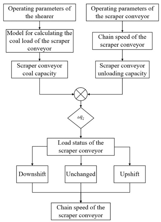
Figure 4.
Flowchart of the graded speed control method based on the coal loaded for the scraper conveyor.
Considering the aforementioned analysis and research, this paper adopted the 15-21020 fully mechanized mining face of a specific coal mine as its subject of investigation. In accordance with the characteristics of the coal cutting process and the actual production data of the working face, the coal quantity calculation model derived in Section 2.2 was employed to statistically analyze the load situation of the scraper conveyor over the course of one production cycle of the working face. The load output power of the scraper conveyor was compared before and after the implementation of speed regulation at the working face, utilizing the aforementioned gear speed regulation control scheme. Table 1 presents the pertinent parameters of the fully mechanized mining face, shearer, and scraper conveyor (Pingdingshan Tianan Coal Mining Co., Ltd., Henan, China). Figure 5 depicts the actual operating trajectory of the shearer engaged in oblique cutting and feeding at the end of the groove. Table 2 outlines the process flow and operating parameters of each mining stage under the aforementioned trajectory.

Table 1.
Parameters of 15-21020 mining face and related equipment.
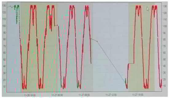
Figure 5.
A photograph of the operating trajectory of the shearer in the 15-21020 mining face.
Table 2.
Bidirectional mining process and related parameters of shearer.
During the production process of this extensive mining face, the scraper conveyor operated at its maximum speed of 1.31 m/s, with a motor power output of 800 kW, and the speed remained constant throughout the entire operation involving three machines in coal extraction. The data obtained from the site indicate that, due to the inability to directly measure the quantity of coal on the scraper conveyor, the output power required for the transportation of materials by the scraper conveyor over the course of a production cycle (192 min) under the specified operating conditions was calculated to illustrate the load of the scraper conveyor. The result is presented in Figure 6a.
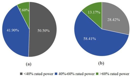
Figure 6.
The scraper conveyor’s output power for a production cycle: (a) rated speed; (b) graded speed regulation.
The data indicate that 50.5% of the time the output power required to transport the load was less than 40% of the rated power during the entire working process. For 92.4% of the time, the power required to transport the load of the scraper conveyor did not reach 60% of the rated power. This demonstrates that the scraper conveyor operated in a high-power but low-load state for extended periods during operation. This not only leads to energy waste but also causes unnecessary deterioration of the equipment. Consequently, it is obvious that regulating the speed of the scraper conveyor is crucial.
The operating speed of the scraper conveyor was set to three gears, corresponding to 60%, 80%, and 100% of the rated chain speed (0.8, 1, and 1.31 m/s, respectively). This was done in order to align the three gear speeds with the three conditions of light-load, half-load, and full-load of the scraper conveyor. The traction speed of the coal mining machine and the amount of coal cut remained constant. Following the adjustment of the scraper conveyor to the operating chain speed of each process stage through the implementation of a gearing speed control strategy, the ratio of the output power required to transport the same amount of coal to the rated power of the scraper conveyor during a coal cutting cycle was recalculated. The results are presented in Figure 6b. The proportion of time when the required output power of the scraper conveyor transporting the load is less than 40% of the rated power is 28.42%. This is followed by the proportion of time when the required output power of the load is more than 40% and less than 60% of the rated power, which accounts for 58.41%. Finally, the proportion of time when the required output power of the load is more than 60% of the rated power is 13.17%. In comparison to the rated chain speed operating conditions, the operating power of the scraper conveyor following speed regulation is more optimal, which reduces the incidence of no-load and light-load operating conditions and consequently reduces the energy consumption of coal transport.
3. The Control Strategy for the Permanent Magnet Drive Scraper Conveyor
3.1. Structure of the PMSM-Driven System
The scraper conveyor is a continuous transport apparatus that uses a chain as its traction mechanism. The conventional drive system for a scraper conveyor employs an asynchronous motor in conjunction with a speed reducer and a soft-start device. This configuration is designed to facilitate the generation of substantial torque at relatively low speeds. However, the lower efficiency of the asynchronous motor and reducer will result in a higher energy consumption for the entire drive system. Furthermore, the inclusion of excessive equipment in the transmission system results in a significant increase in both the overall space requirements and the mass of the entire equipment system. We focused on the traditional scraper conveyor asynchronous motor drive system, which has the disadvantages of a long transmission chain, large volume, and low efficiency. To this end, the SGZ1000/2×1200 mining scraper conveyor (DingMax Mining Machinery Co., Ltd., Shandong, China) was selected as the research object. A permanent magnet variable-frequency speed-regulating integrated machine was designed to replace the three-phase asynchronous motor and deceleration device in the original drive system.
Following the implementation of an upgrade and reformulation of the scraper conveyor permanent magnet motor drive system and asynchronous motor drive system, a comparison is presented in Figure 7. The permanent magnet variable-frequency speed-regulating integrated machine employed a PMSM as the power device for the scraper conveyor. The speed reducer, functioning as an intermediate transmission device, was integrated into a single unit with the permanent magnet motor, resulting in a reduction in the motor’s output speed while an increase in its output torque was observed. The frequency converter played a pivotal role in the operation of the permanent magnet drive system. By regulating the frequency converter, it was possible to achieve flexible starting and speed adjustments to the motor. The integrated drive system had the effect of reducing the overall size and weight of the drive section, thereby saving space for installation. Additionally, the drive system offered the benefits of a wide speed range, high efficiency, and low energy consumption inherent to a permanent magnet synchronous motor. In conclusion, the drive form of the permanent magnet variable-frequency speed-regulating integrated machine was more aligned with the anticipated trajectory of high-efficiency, intelligent, environmentally conscious, and energy-efficient scraper conveyor development.
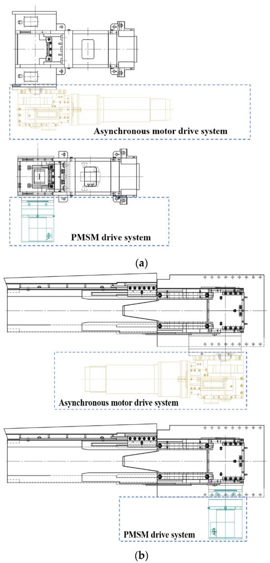
Figure 7.
A structural comparison of the drive systems for the scraper conveyor: (a) head drive system; (b) tail drive system.
3.2. Mathematical Modeling of PMSM
This paper models the PMSM as an ideal motor to facilitate analysis. The surface-mounted PMSM was utilized as the subject of study, employing the id = 0 control strategy. Following decoupling and order reduction via coordinate transformation, the mathematical model of the PMSM in the d-q rotating coordinate system is presented below.
The stator voltage equation of the PMSM can be expressed as follows:
where ud and uq are the components of stator voltage on the d and q axes, id and iq are the components of stator current on the d and q axes, Ld and Lq are the components of the inductances on the d and q axes, ψf is the permanent magnet flux linkage, Rs is the stator resistance, and ωe is the rotor electrical speed.
The stator current equation of the PMSM can be expressed as follows:
The electromagnetic torque equation of the PMSM can be expressed as follows:
where Te is the electromagnetic torque and np is the pole number of the PMSM.
The mechanical motion equation of the PMSM can be expressed as follows:
where TL is the load torque, J is the moment of inertia, ωm () is the rotor mechanical speed, and B is the viscosity coefficient.
3.3. Design of PI Controller
In this paper, two PI controllers were employed to stabilize the current errors on the d and q axes, respectively. The block diagram of the PI current controller is depicted in Figure 8. The output voltages uq and ud of the current controller can be expressed as follows:
where kpd and kpq are the proportionality coefficients of the d and q axis current controllers, respectively. ed and eq are the errors between the reference and actual values of the d and q axis currents, respectively, and ki is the integral coefficient.
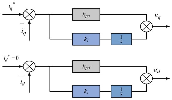
Figure 8.
A block diagram of the PI current controllers.
ed and eq can be expressed as follows:
where id* and iq* are the reference values for the current controllers. id and iq are the actual values for the current controllers.
The parameters of the PI controllers in this paper were designed using the bandwidth method, and the current loop PI parameters can be expressed as follows:
where ωci is the current loop bandwidth.
The speed loop PI parameters can be expressed as follows:
where kps and kis are the proportionality coefficient and integral coefficient of the speed controller, respectively. ωcs is the speed loop bandwidth.
3.4. Design of Improved Sliding Mode Speed Controller
According to Equations (25)–(27), under the id = 0 control strategy and neglecting the viscosity coefficient B, the mathematical model of the PMSM in the d-q coordinate system can be expressed as follows:
The state variables of the PMSM control system can be defined as follows:
where ωr is the reference speed of the PMSM.
Assuming that both ωr and TL are constants, and substituting (32) into (33), the state variables of the PMSM can be described as follows:
The sliding surface s can be defined as follows:
A reaching law can be designed according to the exponential reaching law, which is described as follows:
The output of the sliding mode speed controller can be expressed as follows:
where iq* is the q-axis reference current.
Sliding mode control exhibit strong robustness against external disturbances and parameter variations. In recent years, to enhance control performance, some scholars have integrated sliding mode control with terminal sliding mode control [36], proposing the global fast terminal sliding mode control (GFTSMC) method [37]. This method incorporates the concept of a fast attractor during the reaching phase, offering improved response speed and robustness. In this study, a GFTSMC is applied to the PMSM control system of the mining scraper conveyors.
The global fast terminal sliding surface function can be defined as follows [38]:
where α0, β0, q0, and p0 are the sliding mode approaching parameters and α0, β0 > 0, q0, and p0 are positive odd numbers (q0 < p0).
As the system state approaches equilibrium, the convergence time is predominantly influenced by the linear sliding mode, . Conversely, when the system state departs from equilibrium, the convergence time is primarily shaped by the . By differentiating Equation (38), the following formula can be obtained:
The GFTSMC typically employs an approach with fast terminal attractors, and its reaching law can be expressed as follows [39]:
where α1 and β1 are constants and α1, β1 > 0.
By combining (34), (38), (39), and (40), the block diagram of the GFTSMC speed controller is shown in Figure 9, and the output of the GFTSMC can be expressed as follows:
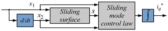
Figure 9.
The block diagram of the GFTSMC speed controller.
The speed error was selected as the state variable for the construction of the sliding mode surface. Once the speed error reached a stable point along the sliding mode surface, the reference current for the q-axis can be calculated. The convergence of the system error and the quality of the sliding mode approaching motion can be achieved by adjusting the parameters. The GFTSMC combines the characteristics of sliding mode control and terminal sliding mode control in the design of the sliding surface. It incorporates the concept of a fast terminal attractor in both the reaching phase and the sliding phase. Additionally, the reaching law of the GFTSMC is continuous and does not include switching terms, which effectively reduces chattering in the system.
Select a Lyapunov function as follows:
Then, derive it to obtain the following:
Since q0 and p0 are positive odd numbers, q0 + p0 is an even number. According to the Lyapunov stability theorem, the system can reach the sliding mode surface in a finite time, and the system is stable.
The block diagram of the sliding mode speed controller based on the GFTSMC method is shown in Figure 10.
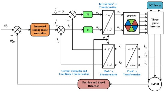
Figure 10.
Block diagram of sliding mode speed controller based on GFTSMC.
4. Simulation and Experiments
This section presents the results of an experimental investigation into the efficacy of the proposed control methods, utilizing a PMSM experimental bench, as illustrated in Figure 11. The bench comprised an RTU controller, an inverter, a DC power supply, a PMSM, a loading motor, and a host computer. The RTU controller in the experimental platform was used in conjunction with the supporting host computer development software RTU Studio (204), which provides an open design system that allowed the simulation models of the different control methods built in MATLAB/Simulink (2020a) to be compiled and downloaded in C code. In order to simulate the utilization of the scraper conveyor in low-speed heavy-load scenarios, the motor in the experimental bench was selected as a permanent magnet synchronous motor with multi-magnetic poles and a low-rotational-speed design. Additionally, this motor was equipped with an encoder to measure the rotor position information. The relevant parameters are presented in Table 3.
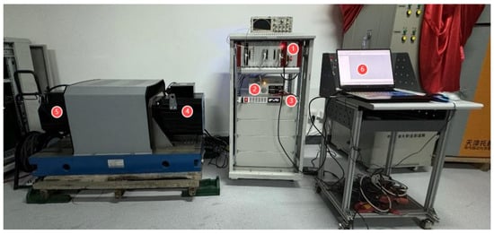
Figure 11.
Photograph of experimental platform: (1) RTU controller; (2) inverter; (3) DC power; (4) PMSM; (5) loading motor; (6) host computer.
Table 3.
Parameters of PMSM.
4.1. Numerical Simulations
In this section, we discuss a PMSM vector control system simulation model based on the improved sliding mode control method that was constructed using MATLAB/Simulink in accordance with the control system structure block diagram illustrated in Figure 8. Subsequently, comparative experiments was conducted on the three control methods. The parameters of the permanent magnet synchronous motor employed in the simulation model were based on the data presented in Table 3, with a simulation time of 2 s. The speed increased from 0 to the rated speed of 165 rpm, and the load torque increased from 0 to 5 N·m in 1 s. In this study, the current loop cutoff frequency was designed as 100 Hz, and the speed loop cutoff frequency was set to 10 Hz. The parameters of the PI current controller were as follows: kpd = 3.39, kpq = 7.69, ki = 282.6, kps = 6.2, and kis = 0.98. The parameters of the SMC speed controller were as follows: c = 90, q = 10, and ε = 5. The parameters of the GFTSMC speed controller were as follows: α0 = 80, β0 = 85, p0 = 11, q0 = 9, α1 = 2200, and β1 = 68,000.
Figure 12 illustrates the comparative analysis of the simulation curves for the three control methods, specifically PI, SMC, and GFTSMC. It can be observed that the PI control method exhibits a notable overshoot during the start-up process, with the motor speed reaching up to 186 r/min, and a prolonged regulation time. The SMC control method results in a motor speed of 181 r/min. In contrast, the GFTSMC controller not only mitigates the overshoot to a certain extent but also enhances the response speed. During the loading process, the motor speed errors under the PI and SMC control methods were 38 r/min and 17 r/min, respectively, and the time required to reach the specified speed once more was considerable. In contrast, the motor speed error under the improved sliding mode control method proposed in this paper was 4 r/min, the speed fluctuation was significantly reduced, and the time to return to the given speed was significantly shorter. Under the GFTSMC method, the actual values of the d and q axis currents closely follow their reference curves, exhibiting fast response times. It is evident that the GFTSMC achieves rapid and smooth speed responses, outperforming the original PI and SMC controllers in speed control effectiveness. Therefore, this study adopted the GFTSMC as the speed controller to replace the original PI controller.
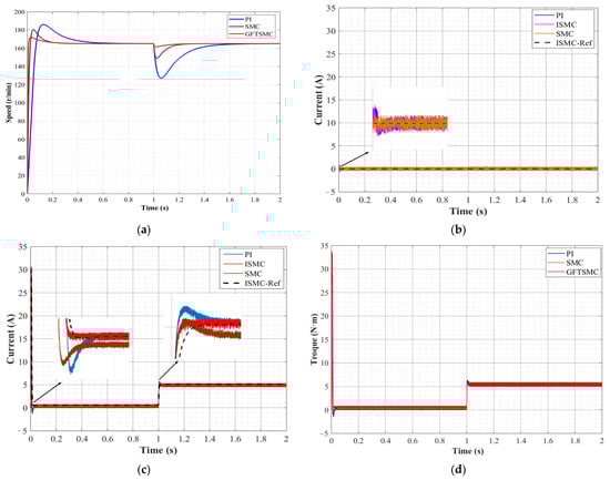
Figure 12.
Simulation curves of three control methods for PMSMs: (a) speed; (b) d axis current; (c) q axis current; (d) electromagnetic torque.
4.2. Platform Experiments
To evaluate the effectiveness of the proposed permanent magnet synchronous motor control method and the feasibility of the speed regulation scheme, the MATLAB/Simulink simulation model developed in Section 4.1 was compiled and uploaded to the control module of the experimental platform. Subsequently, in accordance with the design concept of a graded speed regulation scheme outlined in Section 2.3, a comparative analysis of control methods for a scraper conveyor PMSM drive control system under four distinct operational scenarios, namely, start-up, up-speed regulation, down-speed regulation, and jump-speed regulation, was conducted. The experimental outcomes were subsequently documented and evaluated through the host computer. The sampling frequency of the experimental apparatus was 10 kHz, the duration of the experiment was 2 s, and the resulting curves for each experimental group were generated from the data recorded by the software on the host computer.
4.2.1. Experimental Results of Start-Up Condition
Figure 13 illustrates the comparative velocity curves for the two control methodologies during the start-up stage. The maximum rotational speed of the motor under the original PI control method is 222.6 r/min, which is 72.6 r/min greater than the given speed of 150 r/min. The maximum speed of the motor under the improved sliding mode control method is 159.3 r/min, which is 9.3 r/min higher than the given speed. The results of the speed comparison under different control methods are listed in Table 2 for reference. Table 4 illustrates the comparative speed outcomes of the PMSM control system under distinct control methodologies. In comparison to the original PI control method, the improved sliding mode control (ISMC) used in the global fast terminal method demonstrates a notable advantage in terms of reducing overshoot.
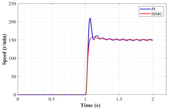
Figure 13.
Speed curves of start-up conditions.
Table 4.
Speed comparison of start-up conditions.
4.2.2. Experimental Results of Speed Regulation
According to the rated speed of the PMSM on the experimental bench, the speed control experiment employed three distinct running speeds: 90 r/min (gear 1), 120 r/min (gear 2), and 150 r/min (gear 3). These speeds were utilized to simulate the running chain speeds under light-load, half-load, and full-load conditions, respectively, during the operation of the scraper conveyor.
Figure 14 illustrates the findings of the speed curves in the speed regulation experiment. Figure 14a depicts the motor speed curve of the up-speed regulation experiment, which simulated a scenario in which enhanced transportation capacity is required due to an increase in coal volume on the scraper conveyor. As illustrated in Table 5, the overshoot of the ISMC is reduced by 34.4%, 38%, and 30.33%, respectively, compared to the overshoot of the PI controller during the entire process of the PMSM completing the speed increase from 0 to gear 1, then accelerating to gear 2, and finally increasing to gear 3. Figure 14b depicts the speed curve of the down-speed regulation experiment, which was employed to simulate a scenario wherein the transport capacity of the scraper conveyor exceeded the coal cutting amount of the shearer during high-speed operation, necessitating a reduction in chain speed. As illustrated in Table 6, the ISMC demonstrates a notable reduction in overshoot during the entire process of reducing the speed of the PMSM, with reductions of 41.33%, 42.66%, and 29.96%, respectively, in comparison to the PI controller. Figure 14c depicts the speed curve of the jump-speed regulation experiment. The up-speed jump experiment was employed to simulate the scraper conveyor in low-speed operation. A substantial quantity of coal or gangue fell suddenly, which was necessary to prevent the phenomenon of stacking coal from appearing. Consequently, the chain speed of the scraper conveyor had to be increased to the highest gear. In a similar manner, the down-speed jumping experiment was designed to simulate the situation that the chain speed of the scraper conveyor needs to be reduced under light-load conditions due to the reduction in coal in the chute after high-speed operation. Table 7 demonstrates that during the acceleration and deceleration of the PMSM, the overshoot of the ISMC is reduced by 36.66% and 26.73%, respectively, in comparison to that of the PI controller.
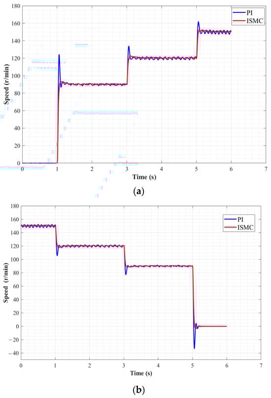
Figure 14.
Speed curves of speed regulation experiments: (a) up-speed; (b) down-speed; (c) jump-speed.
Table 5.
Speed comparison of up-speed regulation experiment.
Table 6.
Speed comparison of down-speed regulation experiment.
Table 7.
Speed comparison of jump-speed regulation experiment.
4.3. Ground Test
In order to verify the performance of the permanent magnet drive system of the scraper conveyor and the effect of the speed regulation scheme, the authors took the SGZ1000/2×1200 scraper conveyor as a research object and a ground test bench of the permanent magnet drive scraper conveyor was constructed, as shown in Figure 15. The upgraded scraper conveyor drive system comprised two TYJVFTJ-560-40 permanent magnet variable-frequency speed-regulating integrated machines and a KXJ1-127 programmable integrated control box (DingMax Mining Machinery Co., Ltd., Shandong, China). The head and tail drive sprockets were connected to the output shafts of permanent magnet integrated machines 1 and 2, respectively. The control box monitored and controlled the operating state of the entire drive system by controlling the converter. The parameters of the scraper conveyor and the permanent magnet integrated machines are presented in Table 8 and Table 9.
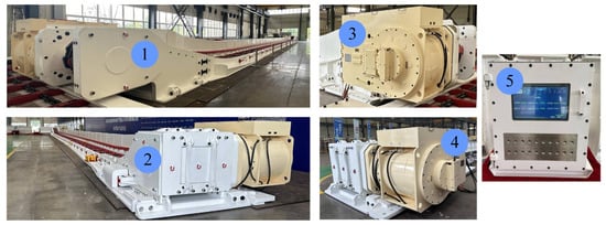
Figure 15.
A photograph of the experimental apparatus of the PMSM drive scraper conveyor: (1) head of the scraper conveyor; (2) tail of the scraper conveyor; (3) PMSM 1; (4) PMSM 2; (5) control box.
Table 8.
Parameters of SGZ1000/2×1200 scraper conveyor.
Table 9.
Parameters of TYJVFJ-560-40 PMSMs.
The test conditions encompassed the start-up, up-speed regulation, and down-speed regulation scenarios for the permanent magnet variable-frequency speed-regulating integrated machine. The objective of the ground test was to evaluate the performance of the scraper conveyor in terms of both operational efficacy and speed regulation under three distinct operational scenarios. The speed, current, and torque curves of the PMSM of the scraper conveyor under different working conditions, as illustrated in Figure 16, Figure 17 and Figure 18, were obtained by exporting the running data from the integrated control box and utilizing Origin (2018) graphing software.
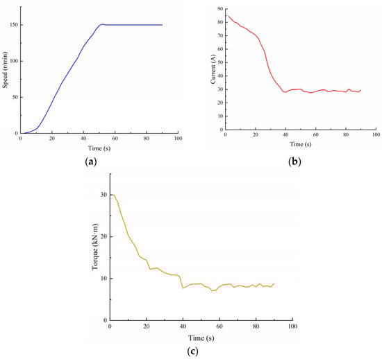
Figure 16.
Test results of permanent magnet drive system under starting conditions: (a) speed; (b) current; (c) torque.
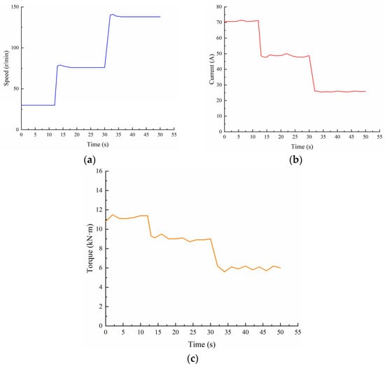
Figure 17.
Test results of permanent magnet drive system under up-speed regulation conditions: (a) speed; (b) current; (c) torque.
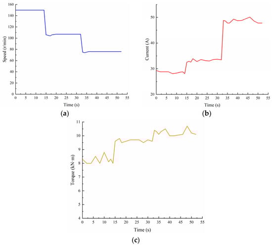
Figure 18.
Test results of permanent magnet drive system under down-speed regulation conditions: (a) speed; (b) current; (c) torque.
Figure 16 illustrates the response curve of the permanent magnet drive scraper conveyor under starting conditions. Figure 16a depicts the speed operation curve of the PMSM of the scraper conveyor, starting from zero speed. The motor employs a flexible starting strategy to mitigate the impact of the shock on the system. The overshoot of the motor speed is minimal under the enhanced sliding mode control method, and the motor speed is stabilized at the specified speed of 150 r/min upon the completion of the starting process. This aligns with the simulated speed curve change trend and demonstrates consistency. Figure 16b,c illustrate the q-axis current and output torque curves of the permanent magnet synchronous motor during the start-up process, respectively. At the instant of start-up, the motor generates a substantial start-up torque (30.1 kN·m) to overcome the inertia associated with the initial acceleration. This torque is maintained at approximately 8 kN·m as the scraper conveyor transitions to a stable operational state. The q-axis current curve of the motor exhibits a similar trend to that of the torque change, which is consistent with the characteristics of the id = 0 control strategy.
Figure 17 illustrates the test curves for the permanent magnet drive scraper conveyor under the up-speed regulation conditions. The motor speeds of gears 1, 2, and 3 were set as 30 r/min, 75 r/min, and 140 r/min, respectively. Figure 17a depicts the speed curve of the PMSM during the gradual increase in scraper conveyor speed from gear 1 to gear 3. During the process of gear switching, the overshoot in motor speed is small, and the motor operates smoothly after reaching the specified value. The change trend is largely consistent with the simulation curve. Figure 17b,c indicate the q-axis current and output torque of the PMSM during the process of up-speed regulation. When the rotational speed is in gear 1, the current of the motor is approximately 71 A and the output torque is approximately 11 kN·m. When the motor rotational speed is increased to gear 2, the current is reduced to approximately 48 A and the output torque is reduced to approximately 9 kN·m. When the rotational speed is in gear 3, the current is further reduced to approximately 25 A and the output torque is subsequently reduced to approximately 9 kN·m. At the highest gear ratio, the current decreases to approximately 25 A, while the output torque decreases to approximately 6 kN·m. Overall, the trends of the two curves are essentially similar.
Figure 18 illustrates the test curve for the down-speed regulation conditions of the permanent magnet drive scraper conveyor. In order to comprehensively evaluate the speed regulation performance of the PMSM drive system of the scraper conveyor in different rotational speed stages within the entire speed regulation range, the gear setting of the down-speed condition differed from that of the up-speed condition. Additionally, the motor rotational speeds of gears 1, 2, and 3 were set as 75 r/min, 110 r/min, and 150 r/min, respectively. The rotational speed curve of the PMSM during the gradual downgrading of the scraper conveyor from gear 3 to gear 1 is shown in Figure 18a. The motor is seen to complete the downgrade action and maintain stable rotational speed during the process of gear switching, which aligns with the simulation results. The q-axis current and output torque curves of the permanent magnet synchronous motor during the upshifting process are shown in Figure 18b,c, respectively. These curves exhibit similarity to the up-speed conditions. The trends of the two curves are basically the same.
5. Conclusions and Further Work
This paper proposes a permanent magnet synchronous motor (PMSM) drive configuration for a scraper conveyor, integrating a speed reduction mechanism and a frequency converter, in response to the prevailing status and developmental trends in permanent magnet drive technology for coal mine equipment. Considering the operational and load characteristics of the scraper conveyor, a graded speed regulation scheme for the scraper conveyor was proposed, along with a control strategy for the PMSM drive system. Finally, the proposed control strategy and speed regulation method were validated through simulation and testing, and the main conclusions are as follows:
(1) The coal quantity calculation model presented in this paper was capable of calculating the actual coal quantity on the scraper conveyor in real time, based on the operational parameters of the coal cutter and the scraper conveyor, as well as the specific coal mining process flow of the working face. The results of the case study demonstrate that the time for the scraper conveyor to operate under light-load conditions is reduced by 22.08% when the proposed graded speed regulation method is employed within a coal cutting cycle. Furthermore, the scraper conveyor is prevented from remaining in a state of high-power consumption and dragging a small load for an extended period.
(2) In this paper, the PMSM was selected as the driving source of the integrated machine, and a reduction device and a frequency converter were integrated. The proposed machine design offers the benefit of a reduction in both the volume of the motor and the length of the transmission chain while enabling the operation of the scraper conveyor at low speed and high torque. The results of the ground tests demonstrate that the permanent magnet variable-frequency speed-regulating integrated machine is capable of meeting the operational requirements of the scraper conveyor.
(3) This paper puts forward an improved sliding mode control methodology for the PMSM, with the objective of mitigating the impact of load disturbances resulting from the dynamic fluctuations in coal cutting volume and the intricate operational parameters of the scraper conveyor permanent magnet drive system. The results of the simulations and experiments demonstrate that, in comparison to the original PI control method, the control system for the PMSM of the ISMC has notable advantages in terms of overshoot and robustness, thereby enhancing the control effect of the scraper conveyor PMSM system.
The data presented in this article has been obtained from ground testing equipment. Given that the entire apparatus is currently undergoing ground testing, it has not yet been subjected to underground industrial trials. Accordingly, the content of this article’s research still requires further improvement. Subsequent work should focus on verifying the performance of the speed control method and permanent magnet drive control system proposed in this paper under real working conditions. This will involve comparative experimental research with other advanced control methods and continuing to improve the regulation speed control function based on industrial test data.
Author Contributions
Conceptualization, X.Z.; methodology, M.R.; software, M.R., H.X. and H.W.; writing—original draft preparation, M.R.; writing—review and editing, X.Z.; visualization, H.X., B.S. and M.G. All authors have read and agreed to the published version of the manuscript.
Funding
This research was funded by the National Natural Science Foundation of China (grant No. 52121003).
Data Availability Statement
Data are contained within the article.
Conflicts of Interest
The authors declare no conflicts of interest.
References
- Lu, E.; Li, W.; Yang, X.; Xu, S. Composite Sliding Mode Control of a Permanent Magnet Direct-Driven System for a Mining Scraper Conveyor. IEEE Access 2017, 5, 22399–22408. [Google Scholar] [CrossRef]
- Wang, H.; Zhang, Q.; Xie, F. Dynamic tension test and intelligent coordinated control system of a heavy scraper conveyor. IET Sci. Meas. Technol. 2017, 11, 871–877. [Google Scholar] [CrossRef]
- Li, L.; Cui, H.; Lian, Z.; Wang, Q. Modeling and Optimization of Soft Start-Up for Hydroviscous Drive Applied to Scraper Conveyor. Math. Probl. Eng. 2019, 2019, 6131364. [Google Scholar] [CrossRef]
- Jiang, S.; Ren, W.; Mao, Q.; Zeng, Q.; Yu, P.; Gao, K.; Wang, L. Dynamic Analysis of the Scraper Conveyor under Abnormal Operating Conditions Based on the Vibration and Speed Characteristics. Shock. Vib. 2021, 2021, 8887744. [Google Scholar] [CrossRef]
- Jiang, S.; Lv, R.; Wan, L.; Mao, Q.; Zeng, Q.; Gao, K.; Yang, Y. Dynamic Characteristics of the Chain Drive System of Scraper Conveyor Based on the Speed Difference. IEEE Access 2020, 8, 168650–168658. [Google Scholar] [CrossRef]
- Xie, C.; Liu, Z.; Xie, M. Analysis of longitudinal and torsional vibration of mining scraper conveyor under the over bending section working condition. J. Vibroengineering 2023, 25, 479–491. [Google Scholar] [CrossRef]
- Jiang, S.; Huang, S.; Zeng, Q.; Chen, S.; Lv, J.; Zhang, Y.; Qu, W. Dynamic Characteristics of the Chain Drive System under Multiple Working Conditions. Machines 2023, 11, 819. [Google Scholar] [CrossRef]
- Yuan, P.; He, B.; Zhang, L. Dynamic modelling of an armoured face conveyor considering the curved chains. Eng. Comput. 2023, 40, 1147–1174. [Google Scholar] [CrossRef]
- Lu, J.; Yang, R.; Mao, J.; Xie, C. Longitudinal torsional vibrations of the chain drive system of mine scraper conveyor. Sci. Rep. 2023, 13, 9174. [Google Scholar] [CrossRef]
- Xu, W.; Junejo, A.K.; Liu, Y.; Hussien, M.G.; Zhu, J. An Efficient Antidisturbance Sliding-Mode Speed Control Method for PMSM Drive Systems. IEEE Trans. Power Electron. 2021, 36, 6879–6891. [Google Scholar] [CrossRef]
- Qu, L.; Qiao, W.; Qu, L. An Extended-State-Observer-Based Sliding-Mode Speed Control for Permanent-Magnet Synchronous Motors. IEEE J. Emerg. Sel. Top. Power Electron. 2021, 9, 1605–1613. [Google Scholar] [CrossRef]
- Xu, B.; Zhang, L.; Ji, W. Improved Non-Singular Fast Terminal Sliding Mode Control with Disturbance Observer for PMSM Drives. IEEE Trans. Transp. Electrif. 2021, 7, 2753–2762. [Google Scholar] [CrossRef]
- Yang, C.; Bu, L.; Chen, B. Energy modeling and online parameter identification for permanent magnet synchronous motor driven belt conveyors. Measurement 2021, 178, 109342. [Google Scholar] [CrossRef]
- Lu, E.; Li, W.; Yang, X.; Xu, S. Simulation study on speed control of permanent magnet direct-driven system for mining scraper conveyor. Int. J. Eng. Syst. Model. Simul. 2018, 10, 1–11. [Google Scholar] [CrossRef]
- Chen, J.; Li, W.; Sheng, L.; Jiang, S.; Li, M. Study on reliability of shearer permanent magnet semi-direct drive gear transmission system. Int. J. Fatigue 2020, 132, 105387. [Google Scholar] [CrossRef]
- Li, S.; Zhu, Z.; Lu, H.; Xue, Y.; Shen, G. Time-dependent fatigue reliability estimation and optimal design of scraper chains under corrosive wear effect. Mech. Based Des. Struct. Mach. 2024, 52, 7886–7903. [Google Scholar] [CrossRef]
- Wang, Y.; Guo, W.; Zhao, S.; Xue, B.; Xing, Z. A Scraper Conveyor Coal Flow Monitoring Method Based on Speckle Structured Light Data. Appl. Sci. 2022, 12, 6955. [Google Scholar] [CrossRef]
- Ren, W.J.; Wang, L.; Mao, Q.H.; Jiang, S.B.; Huang, S. Coupling Properties of Chain Drive System under Various and Eccentric Loads. Int. J. Simul. Model. 2020, 19, 643–654. [Google Scholar] [CrossRef]
- Wang, X.; Li, B.; Wang, S.; Yang, Z.; Cai, L. The transporting efficiency and mechanical behavior analysis of scraper conveyor. Proc. Inst. Mech. Eng. Part C J. Mech. Eng. Sci. 2018, 232, 3315–3324. [Google Scholar] [CrossRef]
- Jiang, S.; Lv, J.; Zeng, Q.; Zhang, Q.; Zhang, Y.; Qu, W.; Cui, J. Dynamic characteristics of scraper conveyor chain drive system under the impact condition of lump coal. PLoS ONE 2024, 19, e299044. [Google Scholar] [CrossRef] [PubMed]
- Zheng, Z.; Chen, D.; Huang, T.; Zhang, G. Coordinated Speed Control Strategy for Minimizing Energy Consumption of a Shearer in Fully Mechanized Mining. Energies 2021, 14, 1224. [Google Scholar] [CrossRef]
- Wang, Y.; Wang, S. Coordinated Speed Planning Strategy of Scraper Conveyor and Shearer Based on Scraper Conveyor Loads Analysis. IOP Conf. Ser. Earth Environ. Sci. 2019, 267, 42044. [Google Scholar] [CrossRef]
- Ma, H.; Zhang, P.; Dong, Y.; Wang, X.; Xia, R.; Li, B. Study on the rigid-discrete coupling effect of scraper conveyor under different chain speed-load conditions. Simul. Model. Pract. Theory 2024, 134, 102943. [Google Scholar] [CrossRef]
- Gil, J.; You, S.; Lee, Y.; Kim, W. Nonlinear sliding mode controller using disturbance observer for permanent magnet synchronous motors under disturbance. Expert Syst. Appl. 2023, 214, 119085. [Google Scholar] [CrossRef]
- Wang, H.; Jiao, T.; Xing, X.; Yang, Y. Speed Regulation of PMSM Systems Based on a New Sliding Mode Reaching Law. IEEE Access 2024, 12, 24062–24070. [Google Scholar] [CrossRef]
- Zou, X.; Ding, H.; Li, J. Sliding mode speed control of permanent magnet synchronous motor based on improved reaching law. COMPEL-Int. J. Comput. Math. Electr. Electron. Eng. 2022, 42, 1335–1348. [Google Scholar] [CrossRef]
- Li, S.; Li, H.; Wang, H.; Yang, C.; Gui, J.; Fu, R. Sliding Mode Active Disturbance Rejection Control of Permanent Magnet Synchronous Motor Based on Improved Genetic Algorithm. Actuators 2023, 12, 209. [Google Scholar] [CrossRef]
- Xu, W.; Qu, S.; Zhang, C. Fast Terminal Sliding Mode Current Control with Adaptive Extended State Disturbance Observer for PMSM System. IEEE J. Emerg. Sel. Top. Power Electron. 2023, 11, 418–431. [Google Scholar] [CrossRef]
- Chen, L.; Zhang, H.; Wang, H.; Shao, K.; Wang, G.; Yazdani, A. Continuous Adaptive Fast Terminal Sliding Mode-Based Speed Regulation Control of PMSM Drive via Improved Super- Twisting Observer. IEEE Trans. Ind. Electron. 2024, 71, 5105–5115. [Google Scholar] [CrossRef]
- Li, D.; Wang, S. Characteristics of new permanent magnetic eddy current drive system of the scraper conveyor. J. Eng. 2021, 2021, 552–558. [Google Scholar] [CrossRef]
- Dai, K.; Zhu, Z.; Shen, G.; Li, X.; Tang, Y.; Wang, W. Modeling and Adaptive Tension Control of Chain Transmission System with Variable Stiffness and Random Load. IEEE Trans. Ind. Electron. 2022, 69, 8335–8345. [Google Scholar] [CrossRef]
- Sheng, L.; Li, W.; Wang, Y.; Fan, M.; Yang, X. Sensorless Control of a Shearer Short-Range Cutting Interior Permanent Magnet Synchronous Motor Based on a New Sliding Mode Observer. IEEE Access 2017, 5, 18439–18450. [Google Scholar] [CrossRef]
- Song, Y.; Liu, G.; Yu, S.; Wang, H.; Zhang, F. Investigation of a Low-Speed High-Torque-Density Direct-Drive External-Rotor PMSM for Belt Conveyor Application. IEEE Access 2023, 11, 110479–110489. [Google Scholar] [CrossRef]
- Lu, E.; Li, W.; Yang, X.; Liu, Y. Anti-disturbance speed control of low-speed high-torque PMSM based on second-order non-singular terminal sliding mode load observer. ISA Trans. 2019, 88, 142–152. [Google Scholar] [CrossRef] [PubMed]
- Zhang, X.; Ren, M.; Wang, H.; Jin, L. Simulation Study on Dynamic Characteristics of the Chain Drive System for Mining Scraper Conveyor Driven by the Permanent Magnet Synchronous Motor. Processes 2024, 12, 165. [Google Scholar] [CrossRef]
- Dong, H.; Yang, X.; Gao, H.; Yu, X. Practical Terminal Sliding-Mode Control and Its Applications in Servo Systems. IEEE Trans. Ind. Electron. 2023, 70, 752–761. [Google Scholar] [CrossRef]
- Xiong, J.J.; Zhang, G.B. Global fast dynamic terminal sliding mode control for a quadrotor UAV. ISA Trans. 2017, 66, 233–240. [Google Scholar] [CrossRef] [PubMed]
- Yuan, L.; Zheng, J.; Wang, X.; Ma, L. Attitude Control of a Mass-Actuated Fixed-Wing UAV Based on Adaptive Global Fast Terminal Sliding Mode Control. Drones 2024, 8, 305. [Google Scholar] [CrossRef]
- Zhu, C.; Tu, Q.; Jiang, C.; Pan, M.; Huang, H. A Cross Coupling Control Strategy for Dual-Motor Speed Synchronous System Based on Second Order Global Fast Terminal Sliding Mode Control. IEEE Access 2020, 8, 217967–217976. [Google Scholar] [CrossRef]
Disclaimer/Publisher’s Note: The statements, opinions and data contained in all publications are solely those of the individual author(s) and contributor(s) and not of MDPI and/or the editor(s). MDPI and/or the editor(s) disclaim responsibility for any injury to people or property resulting from any ideas, methods, instructions or products referred to in the content. |
© 2025 by the authors. Licensee MDPI, Basel, Switzerland. This article is an open access article distributed under the terms and conditions of the Creative Commons Attribution (CC BY) license (https://creativecommons.org/licenses/by/4.0/).