Article

The Structural Design and Pressure Characteristics Analysis of a Magnetic Fluid Sealing Device with Dual Magnetic Sources

1
College of Engineering, Qinghai Institute of Technology, Xining 810000, China
2
Administrative Committee of Zigong High-Tech Industrial Development Zone, Zigong 643000, China
3
Key Laboratory of Fluid and Power Machinery, Ministry of Education, Xihua University, Chengdu 610039, China
4
China Yangtze River Power Co., Ltd., Yichang 443000, China
5
East Route of South-to-North Water Diversion Jiangsu Water Resources Co., Ltd., Huaian 223001, China
6
Gongzui Hydropower General Plant of Guoneng Dadu River Company, Lesan 614900, China
*
Author to whom correspondence should be addressed.
Actuators 2025, 14(11), 561; https://doi.org/10.3390/act14110561 (registering DOI)
Submission received: 23 August 2025 / Revised: 8 October 2025 / Accepted: 8 November 2025 / Published: 18 November 2025
(This article belongs to the Section Actuator Materials)

Abstract

The magnetic fluid seal (MFS) is a novel sealing technique that offers numerous benefits such as non-wear, long life, zero leakage, etc. There are numerous potential applications for it in the fields of energy and chemical industry, aerospace, machinery and electricity, etc. However, compared with a mechanical seal, the pressure of MFS is relatively low, which greatly limits its application promotion. Therefore, in this paper, a magnetic fluid sealing device with a dual magnetic source (present MFS) is firstly designed to improve the sealing pressure. Secondly, the effects of different sealing gaps, pole tooth heights, pole tooth angles and pole tooth eccentricity distances on the sealing pressure are investigated through numerical simulations to obtain the better combination of structural parameters for sealing performance. Finally, a test rig was built to confirm the reliability of the new device, and the results show that the new device’s sealing pressure is significantly higher than the conventional MFS’ at the same rate of rotation, with a maximum increase of 1.69 times and 1.71 times in sealing gas and liquid, respectively. This paper provides a reference for the improvement of sealing pressure of MFS in engineering applications.

1. Introduction

Magnetic fluid is mainly composed of three parts: base liquid, magnetic nanoparticles and surfactant, which is a novel kind of useful material with a stable colloid obtained by dispersing magnetic nanoparticles in a base liquid carrier [1,2,3]. Since it has both the ability of a liquid to flow and the magnetic properties of a solid [4,5,6], and there is no hysteresis phenomenon when the external magnetic field is withdrawn, it has a high application value in engineering. MFS consists of a permanent magnet, magnetic fluid, pole shoe, and shaft (sleeve) [7,8], as shown in Figure 1a below, which mainly utilizes the response characteristics of the magnetic fluid to the external magnetic field to confine the magnetic fluid within the sealing, forming a liquid O-shaped ring to achieve sealing. Compared with traditional mechanical seals, MFS has the advantages of zero leakage, low wear, long life, and self-repair [9,10,11] and has a wide range of applications in the fields of aeronautics, spaceflight, electronics, the chemical industry, energy, machinery, medical care, etc. [12,13,14,15], so that many academics are drawn to it and conduct extensive research on it.
The origins of MFS research can be found in an essay Rosensweig wrote for the journal “Nature” in the 1960s about the fundamental equations of magnetic fluid hydrodynamics, which provided a theoretical framework for MFS research [16]. However, compared with traditional mechanical seals, the MFS has always had the problem of insufficient sealing capacity. To overcome this defect, many scholars began to conduct research from various perspectives in order to enhance the pressure resistance of the MFS. For instance, Chen et al. examined how changes in magnetic fluid temperature affected sealing pressure during the dynamic sealing process and designed a cooling device to improve sealing performance [17]. Palmar et al. developed a two-stage magnetic fluid shielding structure with variable radial gaps. Subsequently, they obtained the optimal magnetic field gradient for the toothed structure through numerical simulation to enhance the sealing pressure [18]. Li et al. studied the influence of turbulence and rotational speed at the sealing interface on the sealing performance. By creating slots on the shaft to reduce the turbulence, the sealing performance was indirectly improved. [19]. Zhang et al. designed a combined labyrinth seal and MFS, which provided a direction for the application of MFS at high pressures and speeds [20]. Wang et al. and others designed a magnetic fluid spiral combined sealing device, which enables the sealing device to operate stably at different rotational speeds [21]. Chen et al. designed a modular magnetic fluid sealing device for the joint rotation sealing of robots, and by using the L-shaped pole piece, they increased the critical sealing pressure by 44.7% [22]. Jiang et al. considered the influence of rotational speed on MFS and proposed a method for optimizing the size of pole teeth based on magnetic coupling optimization. They obtained a combination of pole tooth parameters with excellent sealing performance under different rotational speeds, which plays an important role in optimizing and enhancing the performance of MFS [23]. Yang et al. combined numerical simulation analysis with orthogonal experimental methods to optimize parameters such as the sealing gap, the number of pole teeth, and the height of pole teeth of the sealing structure, thereby enhancing the sealing pressure [24]. Liu et al. integrated multi-stage pole shoe MFS, magnetic grease secondary seal, and an intelligent protection auxiliary system to design a highly reliable magnetic fluid sealing device. This provides a technical reference for magnetic fluid sealing in the ultra-clean field [25]. The above scholars mainly focused on improving the structural design and optimizing the simulation coupling in order to enhance the pressure resistance of MFS. They made outstanding contributions to the development of MFS. However, compared with mechanical seals, the problem of insufficient sealing pressure for MFS still exists.
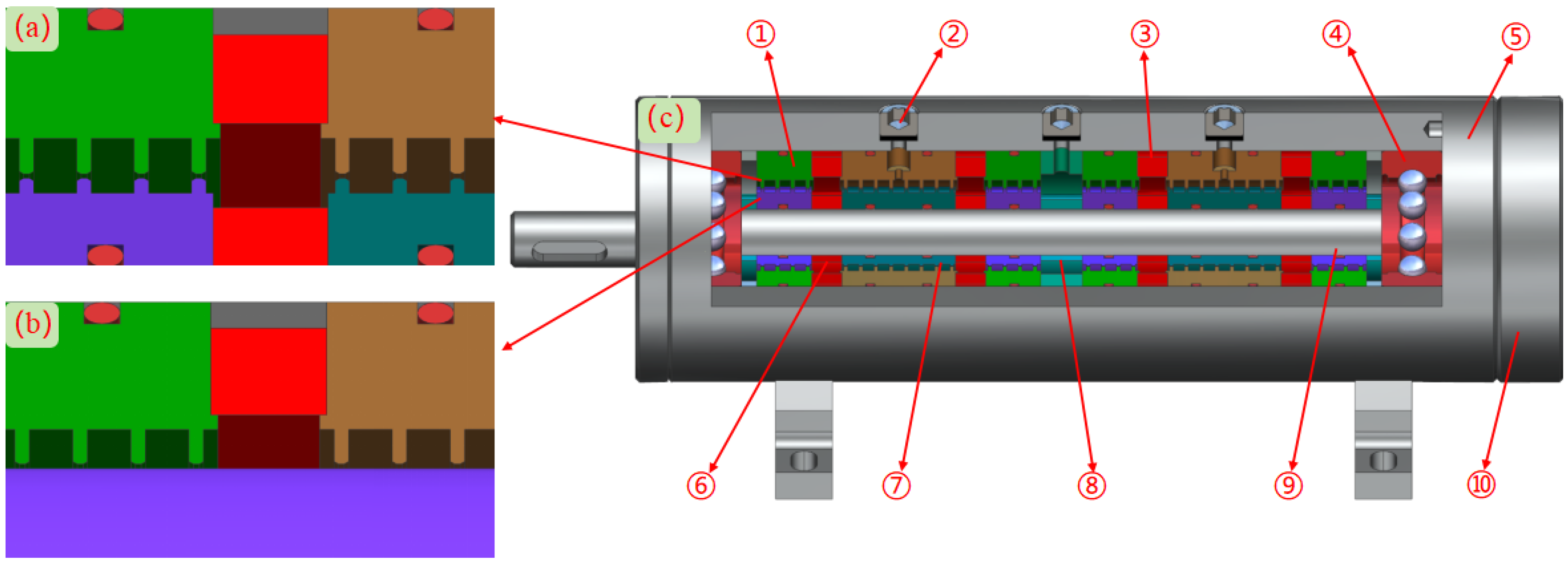
In this context, this paper designs a new type of magnetic fluid sealing structure with dual magnetic sources (we will later call it “present MFS”), and its structural schematic is shown in Figure 1b. Compared with the traditional MFS, we have added an inner permanent magnet and an inner pole shoe on the rotating shaft side, which respectively enhance the magnetic flux of the entire magnetic circuit and increase the magnetic attraction capacity of the pole shoe to solve this problem. Secondly, the effects of different sealing gaps, tooth heights, chamfering angles, and eccentricity distances on the sealing pressure were investigated through numerical simulations to further improve the sealing pressure of the present MFS. Finally, a test rig was built to examine the sealing performance of the present MFS to ensure its reliability.

2. Theoretical Foundations

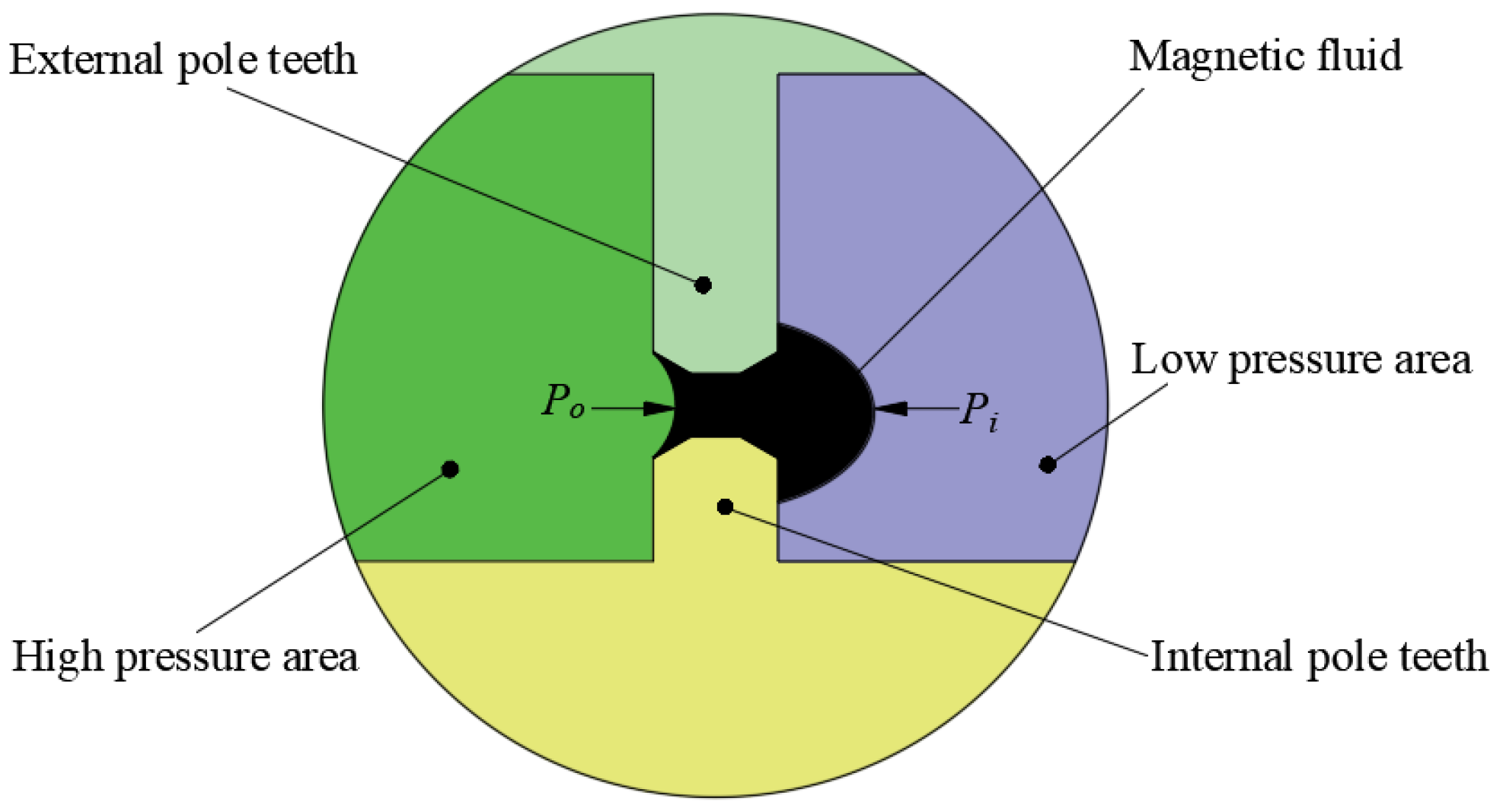
The cross-section schematic of the present MFS’ sealing gap is shown in Figure 2. Under the influence of the external magnetic field, the magnetic fluid is confined in the sealing gap, forming a liquid film “barrier” and isolating the two sides of the region to play the role of sealing. The magnetic fluid gradually travels to the low pressure due to high pressure extrusion as the pressure in the high pressure area steadily increases. Once the differential in pressure between the high and low pressure regions reaches a specific critical value, the magnetic fluid breaks and produces a leakage channel, and the sealing medium leaks. At this time, the pressure difference is the theoretical sealing pressure of the magnetic fluid sealing structure.
Under static conditions, the differential in pressure between the sealing region’s two sides, i.e., the theoretical pressure of the MFS, is derived as follows [26]:
Δ P = P H P L
where P H represents the high-pressure area’s pressure and P L represents the low pressure area’s pressure.
As shown in Figure 2, ignoring the effect of surface tension [26], P H = P o , P L = P i , then:
Δ P = P H P L = P i P o
where P o and P i are the interfacial position pressures on the high- and low pressure regions of the magnetohydrodynamic film, respectively;
Because surface tension and gravity have relatively little effect, we disregard them. In addition, assuming that there is no normal phase component of the magnetic flux density in the boundary, the modified Bernoulli equation can be used to obtain it [27]:
P = u 0 0 H M d H 1 2 ρ f V 2 + C
Thus, the theoretical pressure of the MFS under static conditions is:
Δ P = P H P L = P i P o = μ 0 H min H max M d H
where H min and H max denotes the magnetic fluid film’s minimum and maximum magnetic field intensity, respectively; M denotes the magnetic fluid’s magnetization intensity.
Subsequently, we presume that the magnetic fluid can attain the saturation magnetization state, then the above equation M = M s = c o n s t , and hence it is possible to simplify the static seal’s theoretical sealing pressure as:
Δ P = μ 0 M s H min H max d H = μ 0 M s H max H min
For multistage sealing, assuming that the pressure of each pole tooth is consistent, the pressure’s total value equals:
Δ P total = n M s B max B min = n M s Δ B
where n is the number of sealing stages; B max and B min denotes the magnetic fluid film’s minimum and maximum magnetic flux density, respectively; Δ B is the difference of the magnetic flux density, where: B = μ 0 H .
For dynamic seals, a negative value ψ is added to the theoretical static sealing pressure equation to account for factors such as centrifugal force [28]:
Δ P = M s Δ B + ψ
Therefore, the static sealing pressure is generally greater than the dynamic seal. However, due to the centrifugal force and other factors, in addition to the complex interfacial changes involved in sealing liquid, there is no directly usable formula to accurately calculate this negative factor.

3. Simulation Analysis of Pressure Characteristics

Due to the MFS device’s narrow sealing gap, it is impossible to precisely and directly detect the magnetic flux density within it. In addition, there are many parameter variables affecting the sealing pressure, and if the processing and production of the test device one by one is costly, the cycle time is long, and the test workload is large, the use of numerical simulation analysis can be faster, convenient, and economical to explore how each factor affects the sealing pressure and to improve the structural parameters [29].

3.1. Introduction to Model

The magnetic fluid sealing device mainly consists of permanent magnets, a rotating shaft or shaft sleeve, magnetic fluid, and pole shoes. Under the action of the magnetic field force, the magnetic fluid firmly adheres to the sealing gap, forming many liquid sealing rings, which seal the sealing gap and thus achieve the sealing effect. Compared with the traditional magnetic fluid sealing (as shown in Figure 3a), the present sealing structure with an inner permanent magnet and inner pole shoes on the shaft (as shown in Figure 3b) enhances the magnetic attraction capacity of the magnetic fluid sealing device and increases the magnetic flux density in the sealing gap, thereby increasing the magnetic field force that constrains the magnetic fluid in the sealing gap and enhancing the sealing pressure. The composition of the new magnetic fluid sealing structure is shown in Figure 3c.
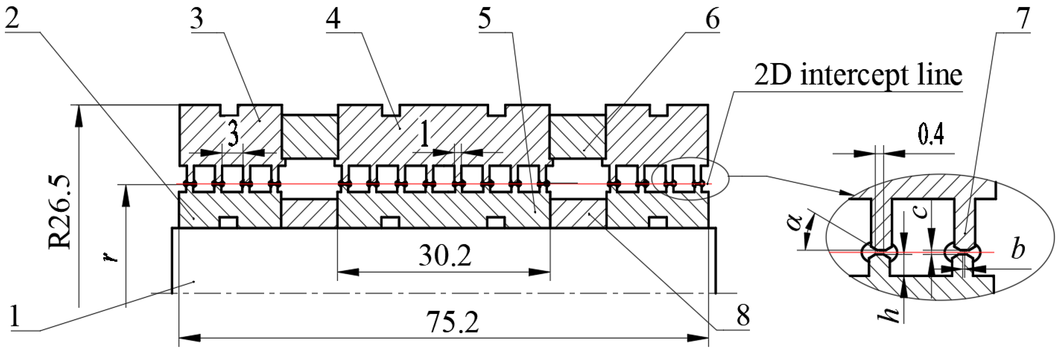
The core of the sealing performance of the MFS lies in the strength of the magnetic field formed between the permanent magnet, the pole shoe, and the shaft sleeve. Therefore, we only need to conduct magnetic field simulation calculations for the components such as the permanent magnet, the pole shoe, and the shaft sleeve. Moreover, since all the components are axisymmetric models and the sealing structures on both sides of the magnetic isolation ring are the same, in order to improve the calculation speed and accuracy, we only need to calculate the sealing pressure of the sealing structure on one side of the magnetic isolation ring and then multiply the obtained sealing pressure by 2 to obtain the sealing pressure of the entire sealing structure, as shown in Figure 3. Therefore, the simplified MFS 2D model obtained is shown in Figure 4, and the initial structural parameters of the model are as shown in Table 1:

3.2. Material Selection and Boundary Condition Setting

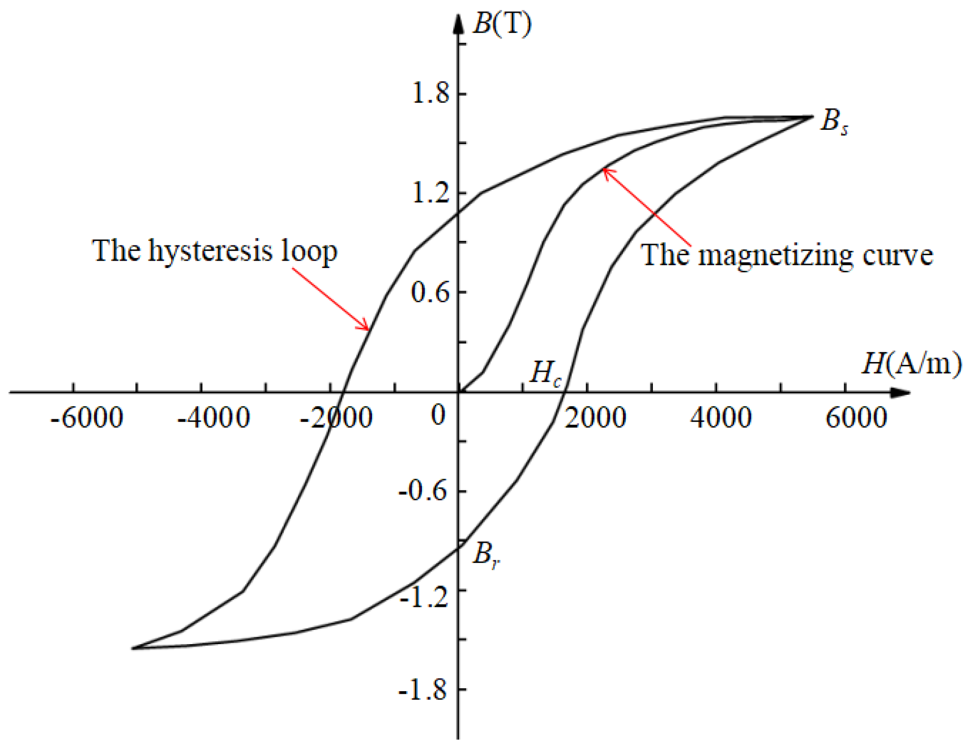
In this paper, the NdFeB material of grade N38H is selected as the permanent magnet, which has a large coercivity of 900 kA/m and a remanent magnetization of 9.95 × 10 5 A/m. The pole shoe and shaft are made of 2Cr13 with a relative permeability of 2000 (when the magnetic field intensity is 1300 A/m). In addition, using the B-H curve magnetization relationship to calculate the magnetic field, the magnetization curve and hysteresis loop of 2Cr13 are shown in Figure 5 below. The permanent magnet is calculated using the remanent magnetic flux density magnetization model relationship, and it is set to be axially magnetized. The magnetic field lines emanate from the N pole of the permanent magnet and return to the S pole.
The magnetic fluid used is a self-made binary ester-based magnetic fluid with a saturation magnetization of 22 kA/m in the laboratory. Its density is 1.47 × 10³ kg/m3, viscosity is 100 ± 20 mPa·s, and relative permeability is 1.05. Since the relative permeability of the shell and other parts is basically equal to that of air, in the calculation, they are all treated as the air domain, and the relative permeability magnetization model is selected for calculation.

3.3. Mesh Spacing and Irrelevance Verification

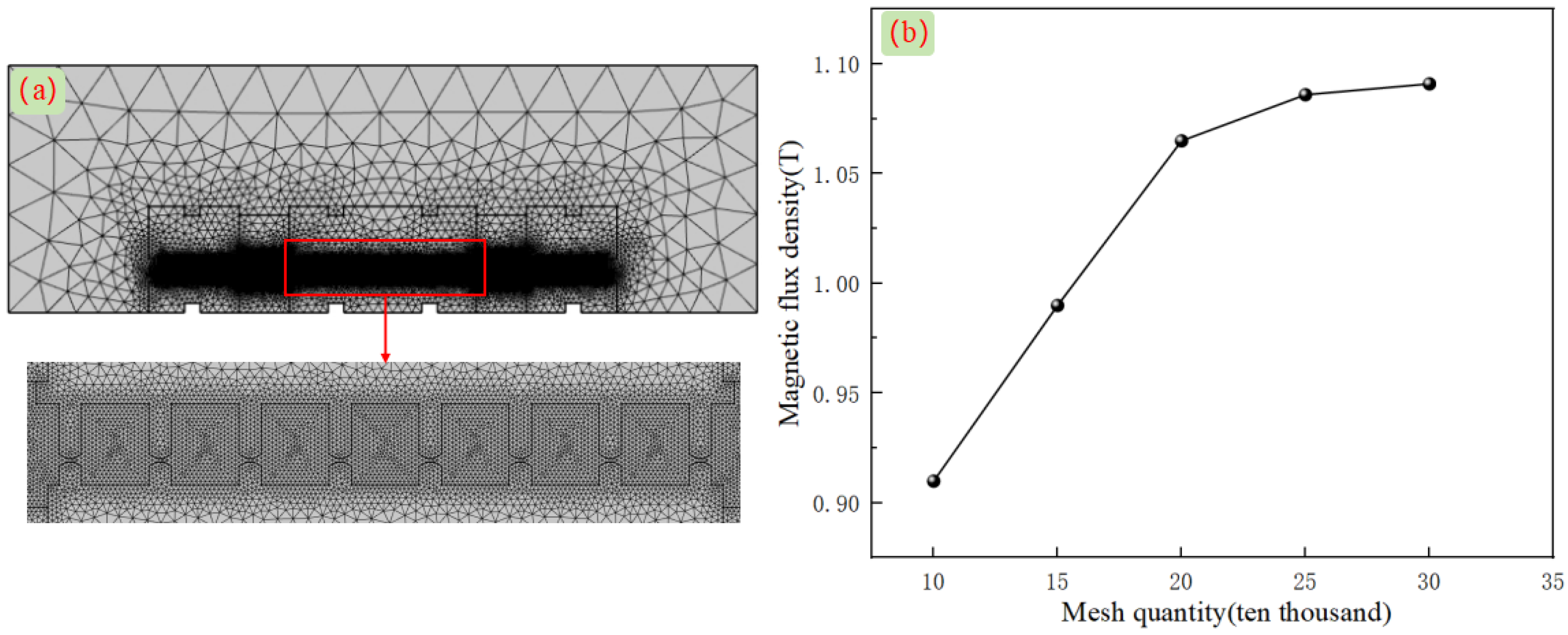
Before the simulation calculation, we used the COMSOL Multiphysics 6.0 software to conduct the unstructured grid division for the magnetic fluid sealing device. The maximum cell size of the grid was set at 0.7 mm, the minimum cell size was set at 0.01 mm, the maximum growth rate was 1.1, and the curvature coefficient was 0.2. The sealing pressure is closely related to the magnetic flux density under the pole teeth, so the area under the pole teeth is encrypted and customized.
The maximum mesh cell size is set to 0.05 mm, and the curvature factor is set to 0.05. The grid division results are shown in Figure 6a. The minimum cell mass of the grid is 0.491, and the average cell mass of the grid is 0.927. In order to avoid the influence of the number of grids on the calculation results, different grid numbers are taken to calculate the magnetic induction strength under the first pole tooth on the sealing device, and the results are shown in Figure 6b. When the number of grids is about 250,000, the magnetic induction strength no longer changes, significantly; in order to save computer resources, we choose the number of grids of 250,000 for the calculation.

3.4. Numerical Simulation

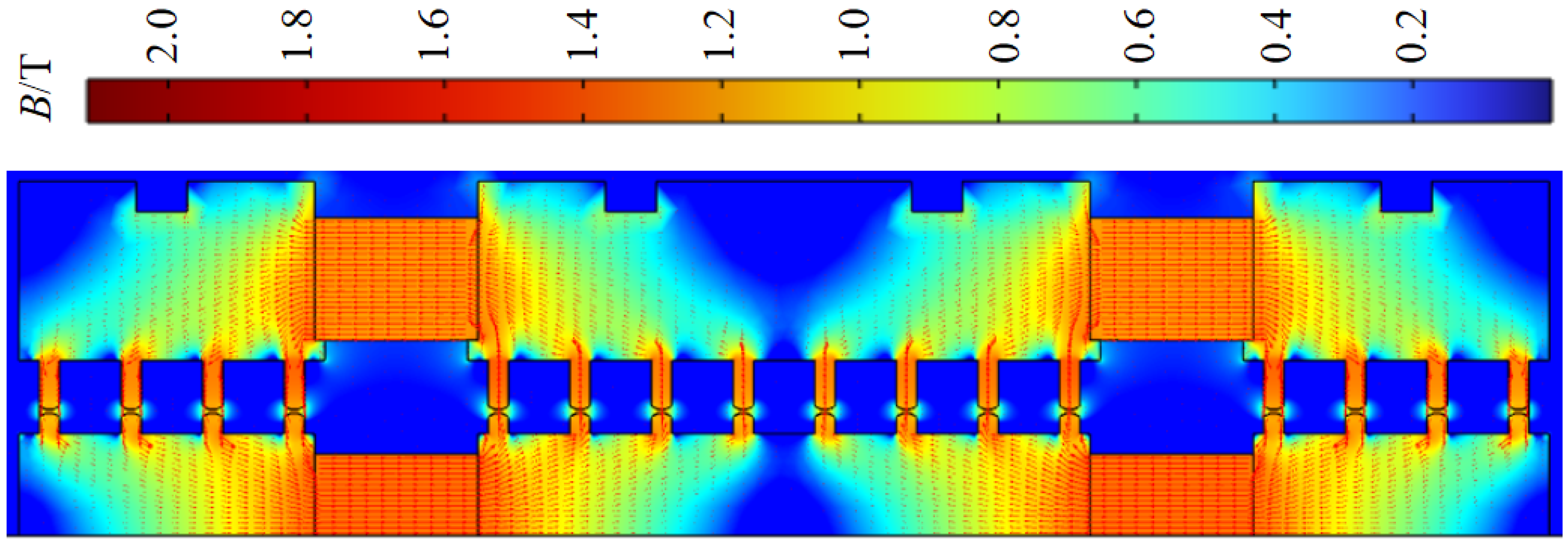
Based on the magnetic fluid sealing model, material selection, and boundary condition settings described in the previous text, the magnetic field simulation cloud map of the magnetic fluid sealing structure as shown in Figure 7 was obtained. From the figure, it can be seen that the magnetic fields generated by the external permanent magnet and the internal permanent magnet both start from the N pole of the permanent magnet and finally return to their S pole through the outer pole boot and the inner pole boot, forming a closed magnetic circuit. In addition, when the pole boots are magnetized, the magnetic field generated by the permanent magnet will converge at the top of the pole teeth, causing the magnetic flux density at the top of the pole teeth to be significantly higher than at other positions. This also conforms to the magnetic flux density distribution law of the magnetic fluid sealing structure, that is, the magnetic flux density reaches its peak at the tooth tip and reaches its valley at the tooth slot [30]. This also indicates that the magnetic field numerical simulation in this paper is correct.
For MFS, the magnitude of the pressure that the “O”-shaped magnetic fluid liquid ring formed below the pole teeth bears is undoubtedly the main factor determining the excellent performance of MFS [31]. As for the magnetic fluid sealing device designed in this paper, there is no doubt that the center of the sealing gap formed by the upper and lower pole teeth is the weakest part of the entire magnetic fluid liquid “O” ring. When subjected to pressure, the leakage of the sealing medium will occur first. Therefore, as long as the magnetic field intensity at this location is calculated and substituted into the pressure resistance Equation (6) for calculation, the sealing pressure of the entire sealing structure can be determined.
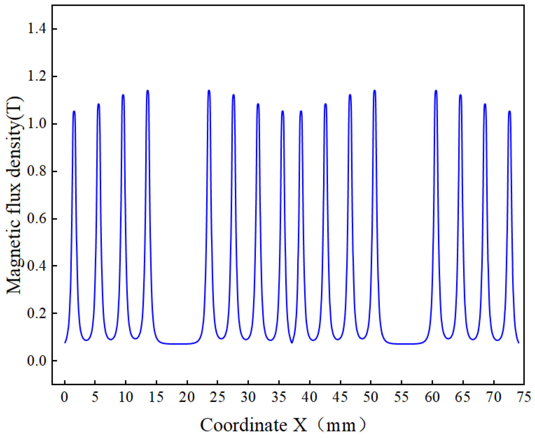
To quantify the sealing gap’s magnetic flux density across the axial direction at the sealing gap’s center, a 75 mm-long 2D intercept line was drawn, and numerical simulation calculations were used to derive the magnetic flux density of the two-dimensional intercept line, as seen in Figure 8 From the figure, it can be observed that the magnetic flux density is alternately changing in peaks and valleys, and the peak is the pole tooth directly below, with a maximum magnetic flux density of 1.097 T, and the valley is the tooth groove directly below, with a minimum magnetic flux density of 0.096 T. The difference of the wave peaks and valleys is taken into the Equation (6), and the sealing pressure of the designed MFS is 740 kPa. In order to obtain a larger sealing pressure, we will improve the structure on the basis of the initial structure parameters. Due to the limited space, this paper mainly investigates the effects of the sealing gap c , the height of the pole tooth h , the chamfering angle α , and the eccentricity distance b on the sealing pressure so as to explore the range of structural parameters with the better sealing performance.

3.5. The Effect of Each Parameter on the Sealing Pressure

3.5.1. The Effect of Gap on Sealing Pressure

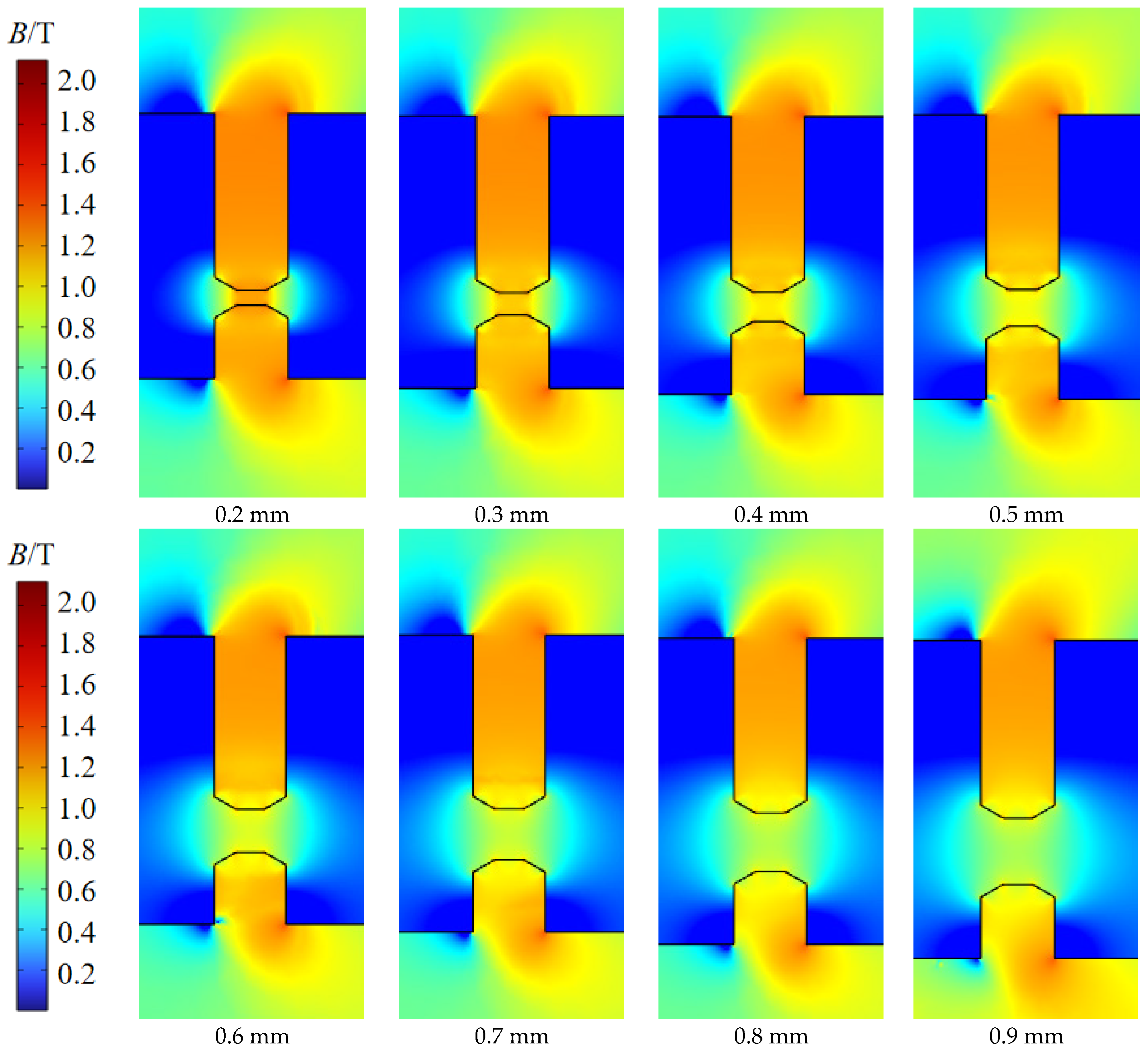
In practice, the sealing gap is crucial to the MFS device’s processing and installation, as well as its sealing function. The 0.1 mm sealing gap is taken as the gradient of change, and in the sealing gap range of 0.2–0.9 mm in this paper, various sealing gaps’ effects on sealing pressure are investigated through numerical simulation calculations, and the magnetic field distribution cloud diagrams are obtained with different sealing gaps as shown in Figure 9 as follows. As the sealing gap progressively widens, the magnetic flux density at its core becomes progressively weaker. This is because the air below the pole teeth has a bigger magnetoresistance and grows as the sealing gap develops. As a result, the sealing gap’s magnetic induction strength gradually decreases.
To numerically assess how various sealing gap sizes affect the magnetic flux density, we draw a 75 mm long 2D intercept line along the axial direction in the center of different sealing gaps according to the method in Section 3.3. The magnetic flux density on the 2D intercept line was calculated by using numerical modeling at various sealing gaps, and the results are shown in Figure 10 below. From the figure, it can be seen that the trend of magnetic flux density changes under different sealing gaps are the same, alternating between peaks and valleys. However, as the sealing gap increases, the average value of the difference in magnetic flux density between the peaks and valleys gradually decreases. The average values of the magnetic flux density difference for the sealing gaps of 0.2 mm and 0.9 mm are 0.983 T and 0.336 T, respectively. The trend of the numerical change in magnetic flux density is consistent with the change trend of the magnetic field distribution cloud chart in the sealing gap shown in Figure 9.
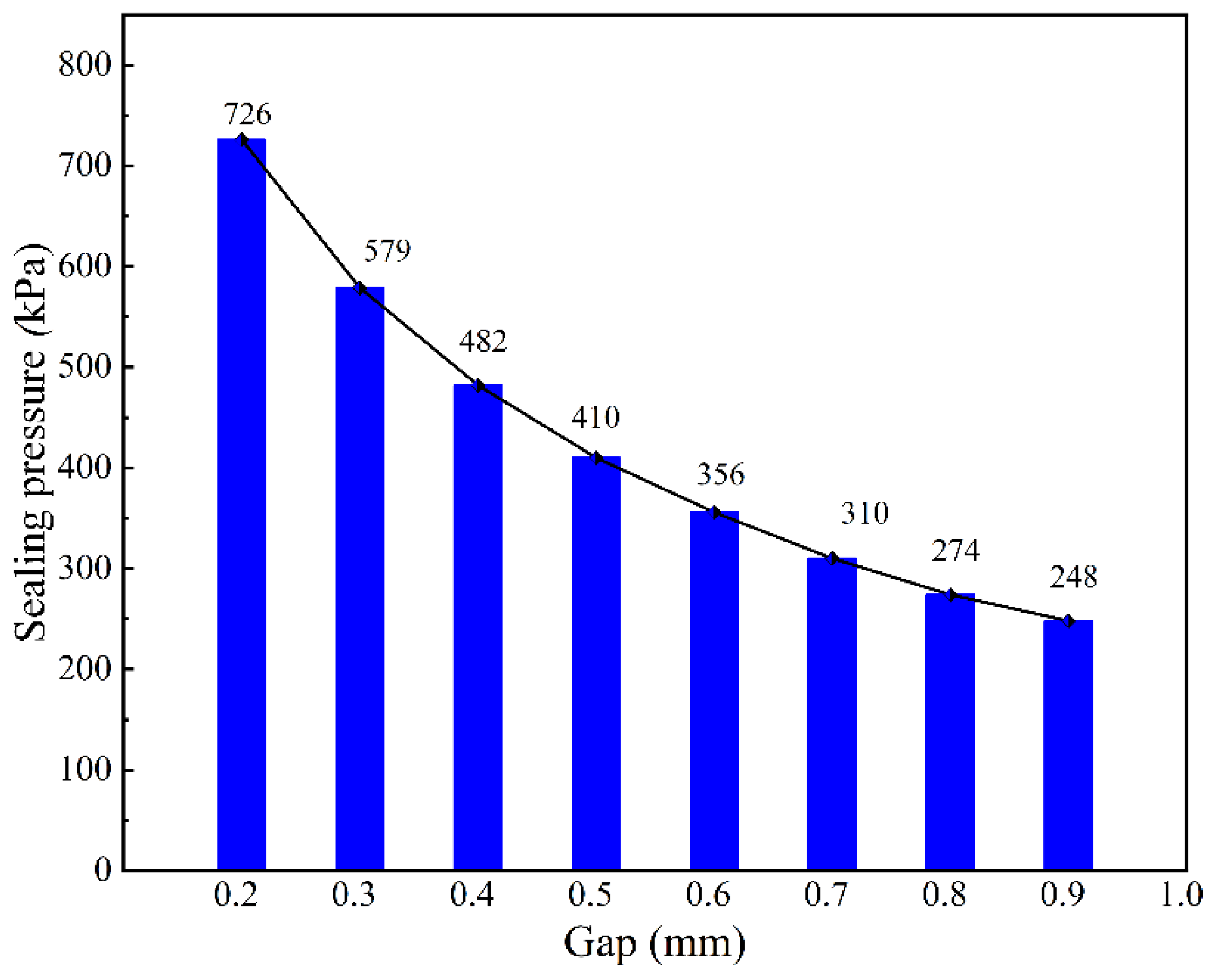
According to the average value of the magnetic flux density difference in Figure 10, substitute it into the Equation (6), so as to more intuitively observe the change trend of the influence of different sealing gaps on the sealing pressure, as shown in Figure 11. From the figure, it can be seen that as the sealing gap increases, the sealing pressure continues to decrease. When the sealing gap is 0.2 mm, the sealing pressure is 726 kPa, and when the sealing gap is 0.9 mm, the sealing pressure drops to 248 kPa. The sealing pressure has decreased significantly. This is mainly because the larger sealing gap leads to an increase in the magnetic resistance of the entire magnetic circuit, thereby reducing the difference in magnetic flux density in the sealing gap and affecting the sealing pressure.

3.5.2. The Effect of Tooth Height on Sealing Pressure

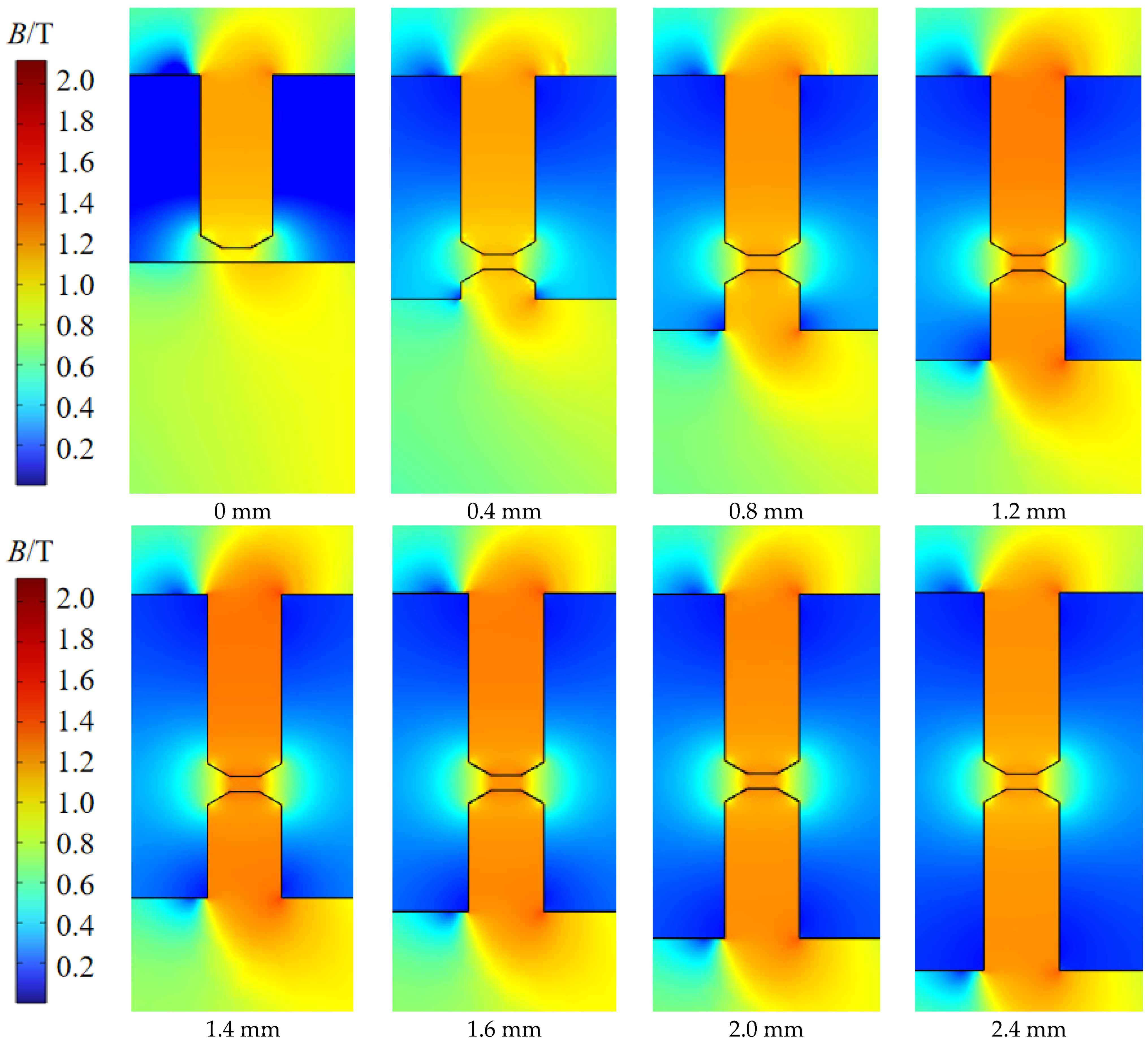
Different from the traditional magnetic fluid sealing structure, which creates a magnetic circuit on the side of the rotor shaft by using a magnetically conductive sleeve, we replace the traditional magnetically conductive sleeve on the rotor shaft with an inner pole shoe structure and increase the magnetic kinetic potential of the entire magnetic circuit by adding an internal permanent magnet, thus enhancing the gap’s magnetic induction strength, which results in the magnetic fluid being subjected to a larger magnetic force in the sealing gap and being bound more firmly. As with the outer polar shoes, the polar teeth on the inner polar shoes also have the effect of magnetization, and it is also important to study the effect of the height of the polar teeth on the inner polar boot on the size of the sealing pressure. In order to investigate how the height of the teeth in the inner pole affects the sealing pressure, we take a height of 0.4 mm as the gradient of change and numerically simulate the sealing pressure with the heights of the pole teeth within the range of 0~2.4 mm and the magnetic field distribution. Cloud diagrams are obtained with different heights of the inner pole teeth, as shown in Figure 12. From the figure, with the gradual increase of the pole tooth height, the center of the sealing gap experiences a gradual increase in magnetic flux density, which reaches its maximum when it reaches 1.4 mm. As the tooth height increases further, the magnetic flux density tends to flatten out and cease to increase.
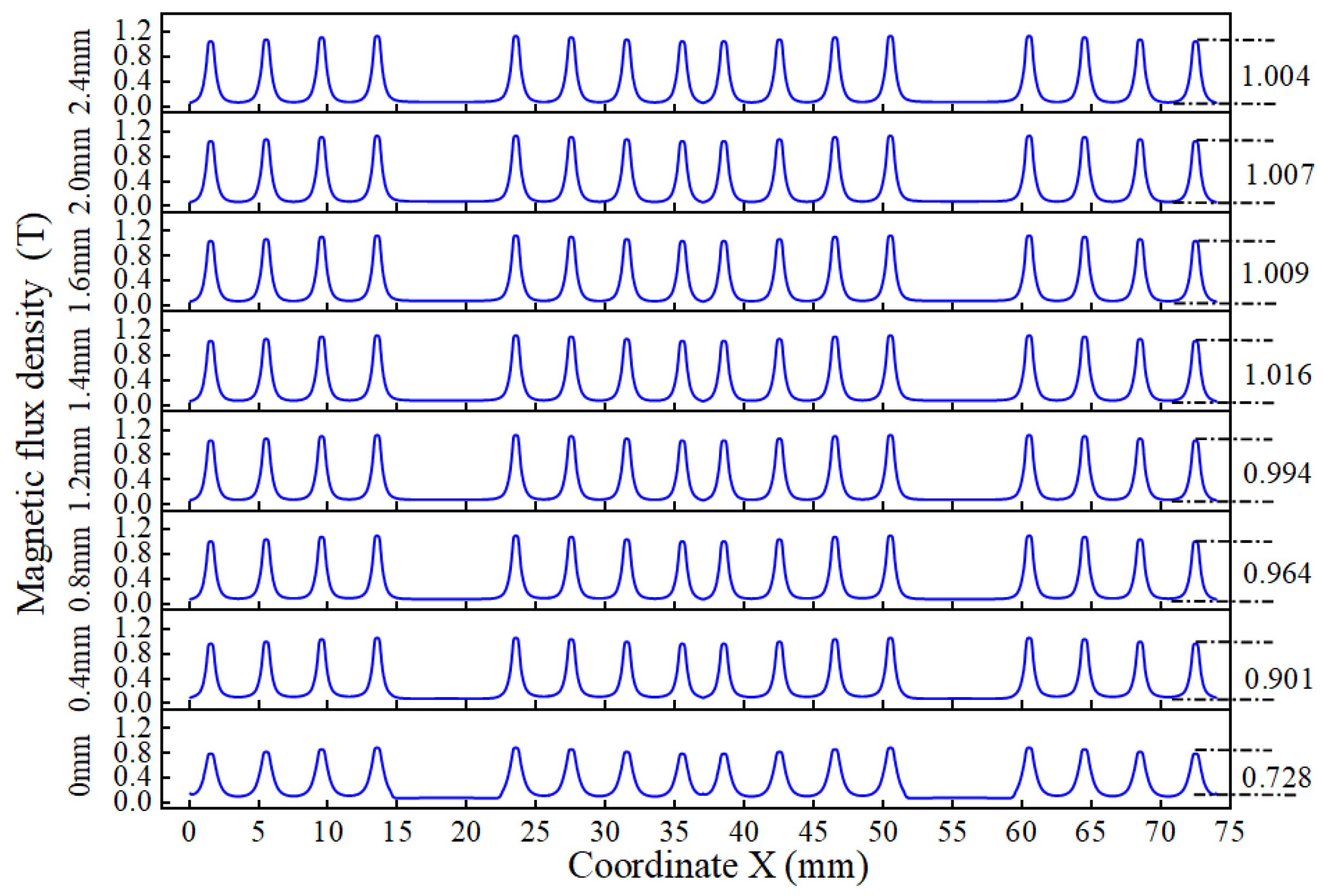
Similar to the method in the previous section, to numerically assess how various inner pole tooth heights affect the magnetic flux density, we also draw a 75 mm long 2D intercept line along the axial direction in the center of sealing gaps according to the method in Section 3.3. The magnetic flux density on the 2D intercept line was calculated by using numerical modeling at various heights, and the results are shown in Figure 13. It can be seen from the figure that the magnetic flux density shows a trend of first increasing, then flattening, and finally slightly decreasing as the height of the pole teeth changes. In addition, when the pole tooth height is 0 mm, i.e., the inner pole shoe has no pole teeth, the difference in magnetic flux density is the smallest, which is 0.728 T, when the height is extended to 1.4 mm, the difference reaches its maximum of 1.016 T. However, with the further height, the magnetic flux density difference value no longer increases and tends to level off, fluctuating between 1.004 T and 1.009 T.
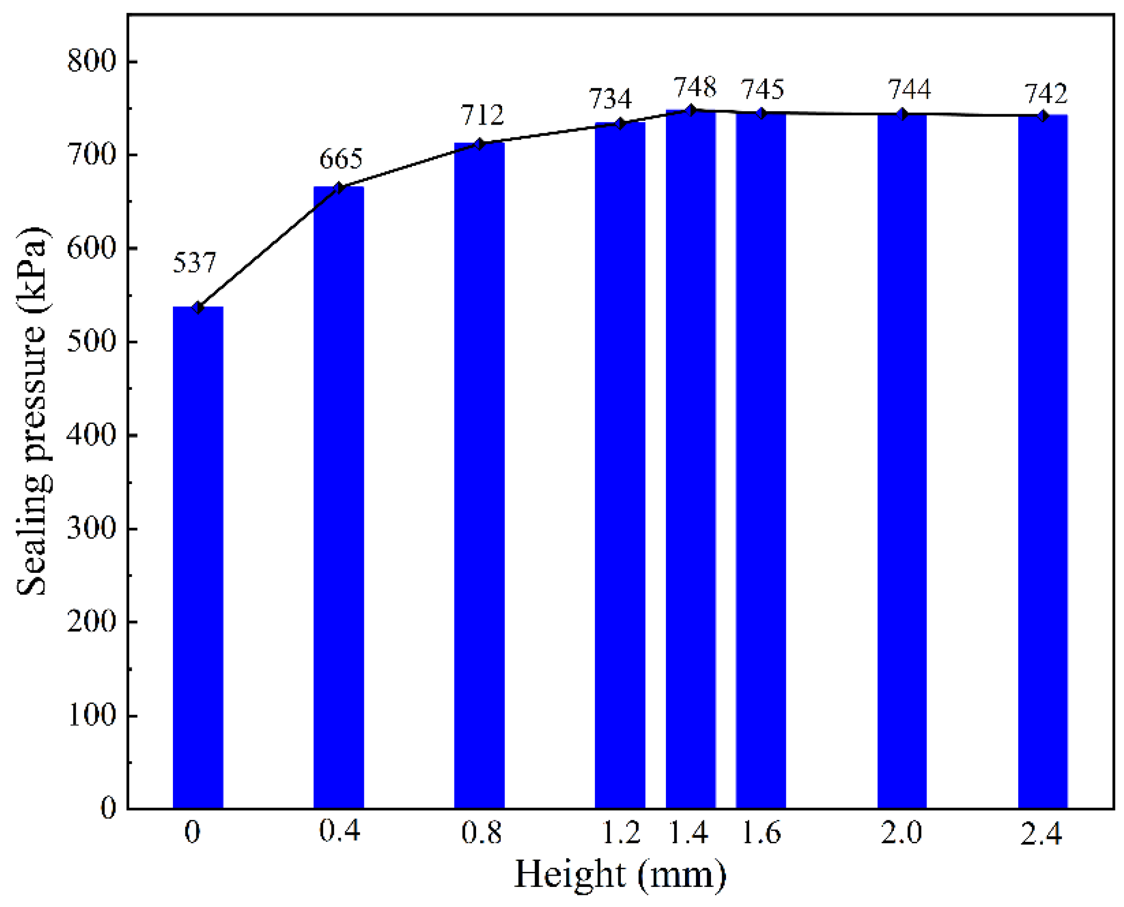
In order to observe the sealing pressure under different heights of the inner pole shoe teeth, the average value of the magnetic flux density difference obtained in Figure 13 was substituted into the Equation (6), resulting in the sealing pressure under different heights of the pole shoe teeth as shown in Figure 14. From the figure, it can be seen that as the height of the pole teeth increases, the sealing pressure first increases, then tends to stabilize, and there is a slight downward trend. When the height is 0 mm, the sealing pressure is 537 kPa, and when the height is 1.4 mm, the sealing pressure reaches the maximum value of 748 kPa. Subsequently, as the height of the pole teeth increases to 1.6 mm, 2.0 mm, and 2.4 mm, the sealing pressures are 745 kPa, 744 kPa, and 742 kPa, respectively, with very slight changes. This is because as the height increases, the magnetic attraction ability of the pole teeth gradually strengthens, causing the magnetic flux density at the center of the sealing gap to gradually increase. However, as the height of the pole teeth further increases, due to the thinness of the pole teeth, their magnetic resistance is also increasing. Therefore, the magnetic flux density in the sealing gap shows a trend of first rising, then stabilizing, and is accompanied by a slight downward trend.

3.5.3. The Effect of Angle on Sealing Pressure

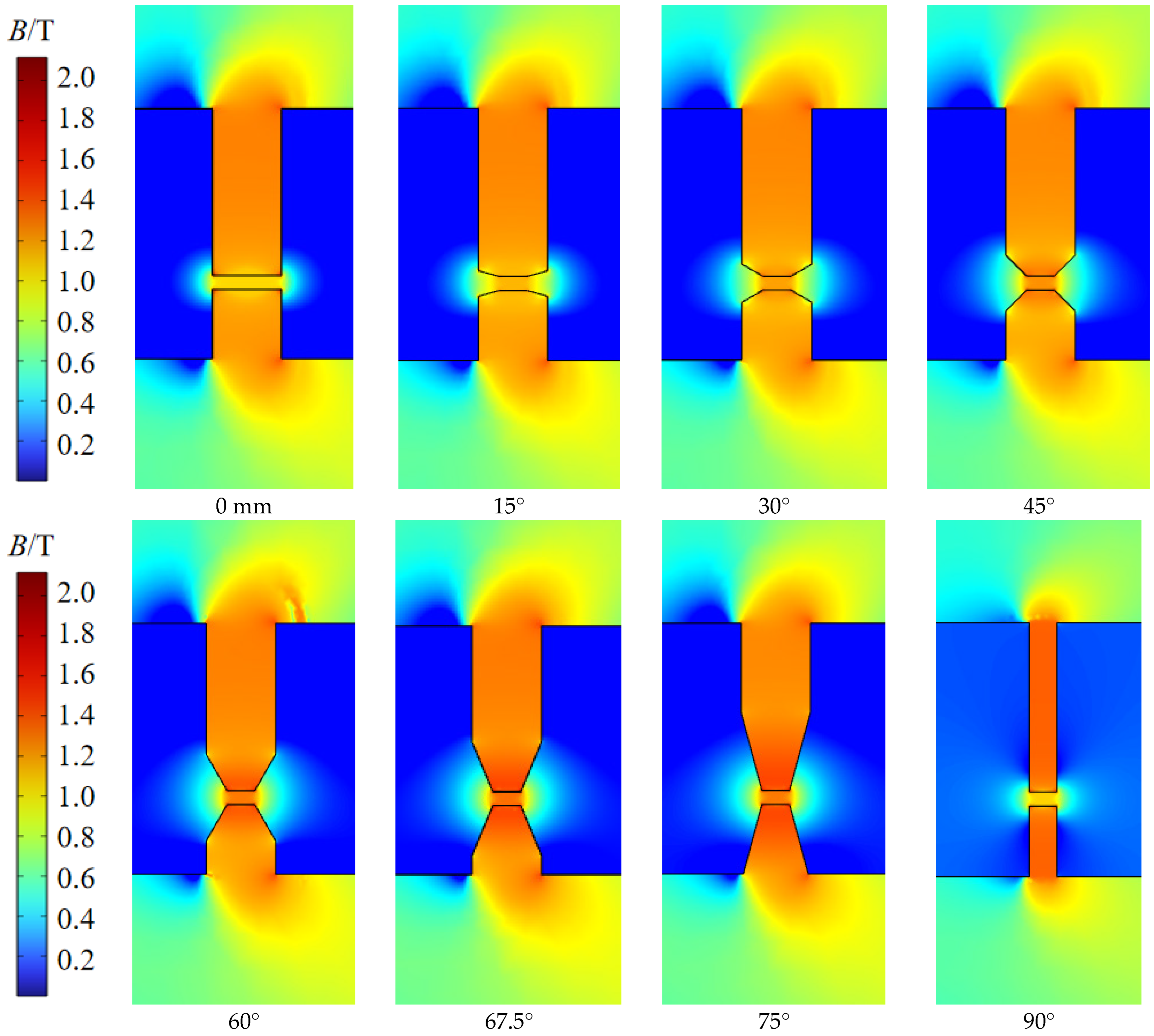
In the traditional MFS structure, the pole teeth are usually designed to be relatively thin to obtain good magnetizing ability, usually below 1 mm, which can easily lead to collision damage of the pole shoe during installation and disassembly, affecting the performance of the MFS. This paper aims to avoid this phenomenon. In the new structure, the pole tooth’s strength is increased by widening its width, and its magnetizing capacity is increased by chamfering the top of the pole tooth. To obtain the best chamfering angle, we take the 15° chamfering angle as the gradient of change and set up a model within the range of 0–90° chamfering angle to carry out numerical simulations to investigate how various chamfering angles affect the sealing pressure, and the results are shown in Figure 15. The magnetic flux density at the sealing gap gradually increases as the angle increases. When the angle reaches 60°, the magnetic flux density approaches its maximum value, and the growth trend gradually slows down. When the chamfer angle is 67.5°, the magnetic induction intensity reaches its maximum value. If the angle is further increased, the magnetic flux density gradually decreases. This is because the increase in the chamfer angle enhances the magnetic accumulation ability of the pole teeth, but it also makes the top of the pole teeth sharper, resulting in an increase in magnetic resistance.
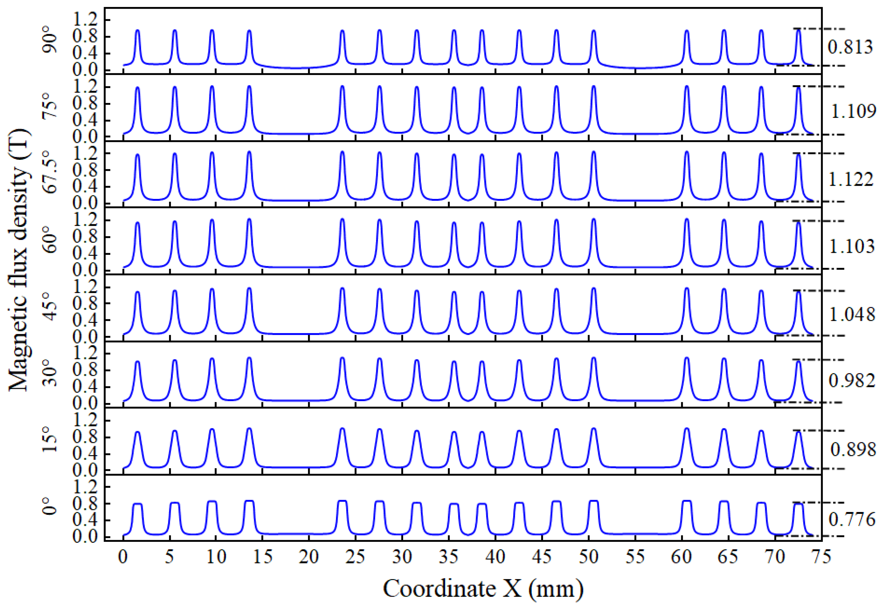
To quantitatively analyze the magnetic attraction capabilities of the teeth at different angles, we continued to draw two-dimensional cross-sections to obtain the magnetic flux density values, and the results are shown in Figure 16. The average value of the magnetic flux density difference in the figure shows a pattern of increasing first and then decreasing with the increase of the chamfer angle. When the chamfer angle is 0° (that is, the teeth have not undergone chamfering treatment), the average value of the magnetic induction intensity difference is the smallest, at 0.776 T. When the chamfer angle is 67.5°, the average value of the magnetic flux density difference is the largest, at 1.122 T. However, as the chamfer angle further increases, the average value of the magnetic flux density difference begins to decrease. When the chamfer angle is 90° (that is, the width of the teeth is the smallest), the magnetic flux density drops to 0.813 T.
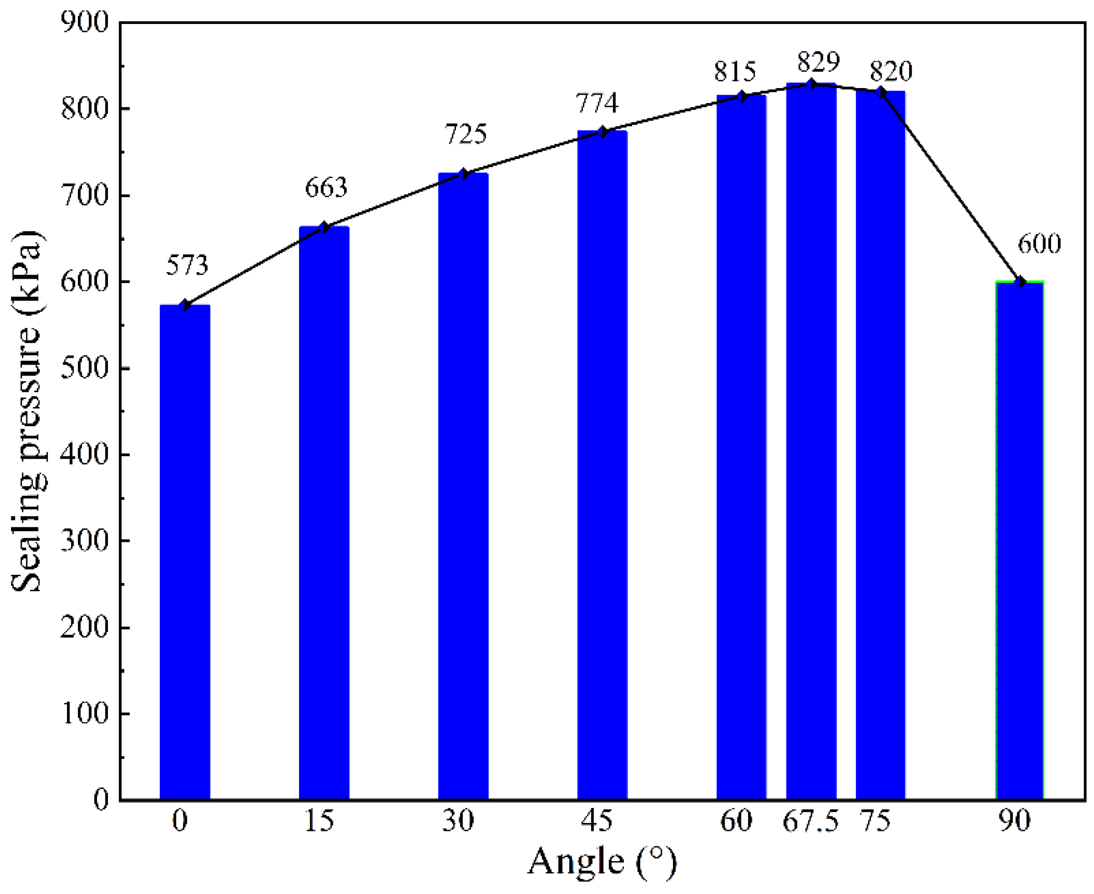
Similarly, in order to study the influence of different chamfer angles on the sealing pressure, the average value of the magnetic flux density difference obtained in Figure 16 was substituted into Equation (6), resulting in the curve showing the variation of sealing pressure with the chamfer angle shown in Figure 17. As can be seen from the figure, as the angle increases, the sealing pressure first rises and then drops. When the angle is 0°, the sealing pressure is 573 kPa, which is the minimum value. When the angle is 67.5°, the sealing pressure is the maximum, at 829 kPa. However, when the angle is between 60° and 75°, the change in sealing pressure is very small, with the maximum difference being only 14 kPa. Therefore, the optimal angle is between 60° and 75°. Under the condition that the influence on the sealing pressure is not significant, the chamfer angle of 60° is more conducive to the processing of the parts and the measurement and detection of the parts after processing. Thus, the extreme chamfer angle is more inclined to be designed as 60°.

3.5.4. The Effect of Eccentricity Distance on Sealing Pressure

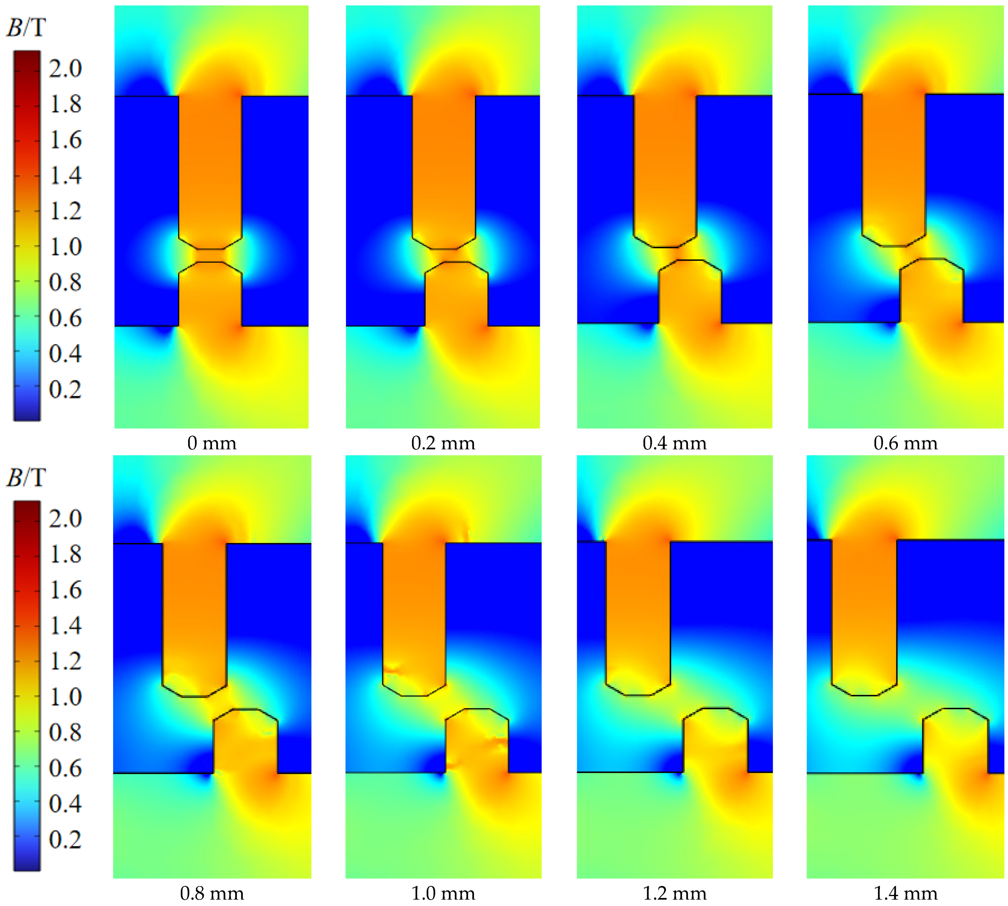
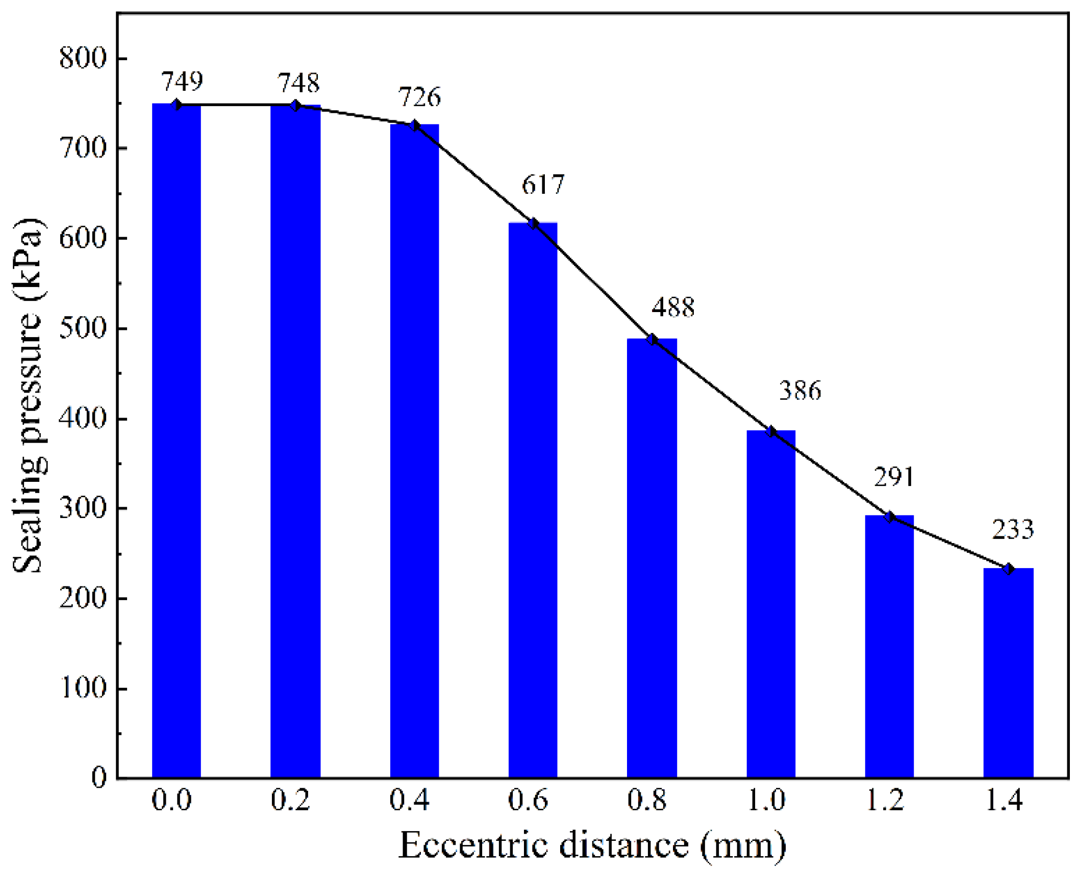
During the actual installation process, due to processing and installation errors, the pole teeth of the inner and outer pole shoes designed in the article may exhibit eccentricity during installation. Therefore, studying the influence of different eccentric distances on the sealing pressure of the magnetic fluid seal is of great significance for the performance prediction of the magnetic fluid seal device. Thus, this paper takes a 0.2 mm eccentric distance as the variation gradient, within the range of 0 to 1.4 mm, through numerical simulation to calculate the influence of different eccentric distances on the sealing pressure. The numerical simulation results are shown in Figure 18. As shown in the figure, as the eccentric distance gradually increases, the magnetic flux density at the center of the sealing gap becomes weaker. Moreover, when the eccentric distance is between 0 and 0.4 mm, the magnetic flux density shows a small downward trend. However, as the eccentric distance gradually increases, after exceeding 0.4 mm, the downward trend of the magnetic flux density gradually accelerates. When the eccentric distance is 1.4 mm, the magnetic flux density reaches its weakest.
Similar to the previous section, we still quantitatively analyze the influence of different eccentric distances on the difference in magnetic flux density by drawing a two-dimensional cross-section line of 75 mm length at the center between the upper and lower teeth. Then, we substitute it into the Equation (6) to obtain the influence of the eccentric distance on the sealing pressure. Through numerical simulation, the magnetic flux density on the two-dimensional cross-section line under different eccentric distances is extracted as shown in Figure 19. As shown in the figure, when the eccentric distance is 0 mm, the average difference in peak and valley magnetic flux density is 1.014 T, and when the eccentric distance is 1.4 mm, the average difference in magnetic flux density is 0.316 T.
Substituting the average values of the magnetic flux density differences obtained from the numerical simulation under different eccentricities into Equation (6), the curve of sealing pressure varying with eccentricity is shown in Figure 20. From the figure, it can be seen that when the eccentricity is 0 mm, the sealing pressure reaches the maximum value of 749 kPa, and when the eccentricity is 1.4 mm, the sealing pressure is the minimum value of 233 kPa. The curve shows an overall trend of gradually decreasing sealing pressure as the eccentricity increases; especially after the eccentricity reaches 0.4 mm, the sealing pressure drops significantly. This is because the initial model’s pitch tooth width is 1 mm. When the eccentricity is within 0.4 mm, the eccentricity formed by the inner and outer pitch teeth of the inner and outer pitch boots can be compensated by the pitch tooth width. However, when the eccentricity is 0.6 mm, the thickness of the outer pitch tooth and the inner pitch tooth is insufficient to compensate for the increase in the sealing gap caused by the increase in the pitch tooth eccentricity. As analyzed in Section 3.5.1, the increase in the sealing gap will increase the magnetic resistance of the entire circuit, thus causing a sudden drop in the sealing pressure calculated by the numerical simulation.

3.6. Comparison of Results Before and After Improved Structure

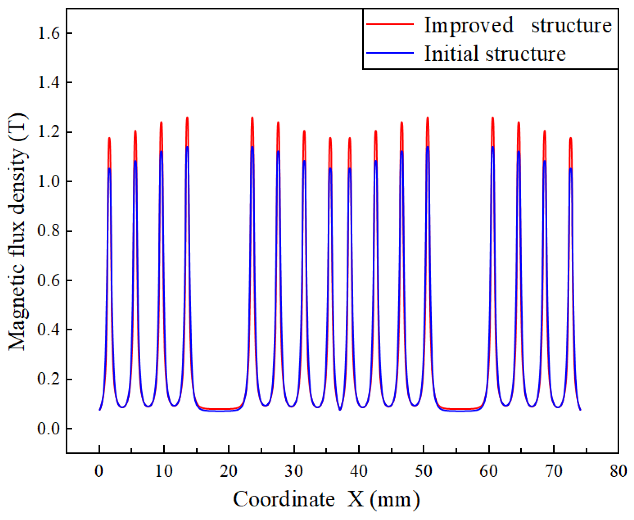
According to the above numerical simulation analysis results, on the initial MFS structure model, the sealing gap was designed to be 0.2 mm, the eccentricity was designed to be 0 mm, the height of the inner pole shoe teeth was designed to be 1.4 mm, and the angle was designed to be 60°. A new two-dimensional model was constructed, and numerical simulation was carried out. The comparison of the magnetic flux density on the 2D intercept line before and after the improved structure is shown in Figure 21.
As can be seen from the figure, the magnetic flux density of the improved structure has significantly increased. By substituting the difference in magnetic flux density into Equation (6), the theoretical sealing pressure of the improved structure is calculated to be 848 kPa. Compared with the theoretical sealing pressure of 740 kPa for the initial model structure, the improved structure has increased by approximately 14.5%.

4. Test Validation

4.1. Test Equipment

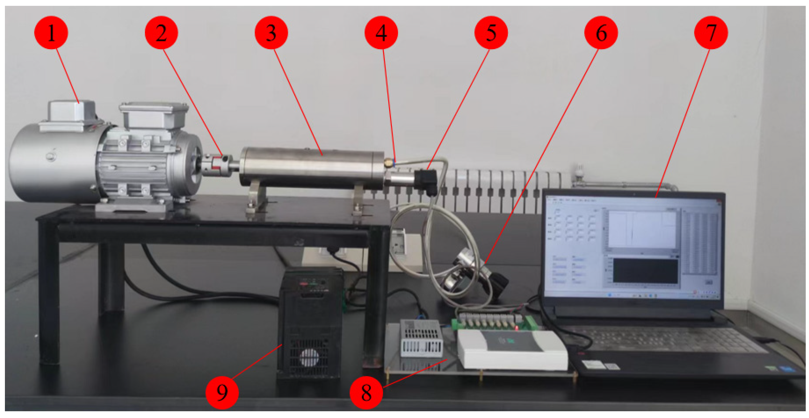
The MFS assembly is processed and installed in the test bench in the laboratory for experimental verification in accordance with the preceding numerical simulation optimization results, and the experimental setup is shown in Figure 22. The variable frequency motor, coupling, seal assembly, pressure sensor, pressure reducing valve, data acquisition unit, frequency converter, and computer make up the majority of the test bench. One end of the pressure-reducing valve is connected to the pressure inlet of the sealing assembly, and one end is connected to the pressure bottle, which can adjust the inlet pressure in real time. The pressure in the sealing cavity can be displayed on the computer in real time through the pressure sensor via the data acquisition card. The specific parameters of the experimental device are shown in Table 2 below.

4.2. Test Method

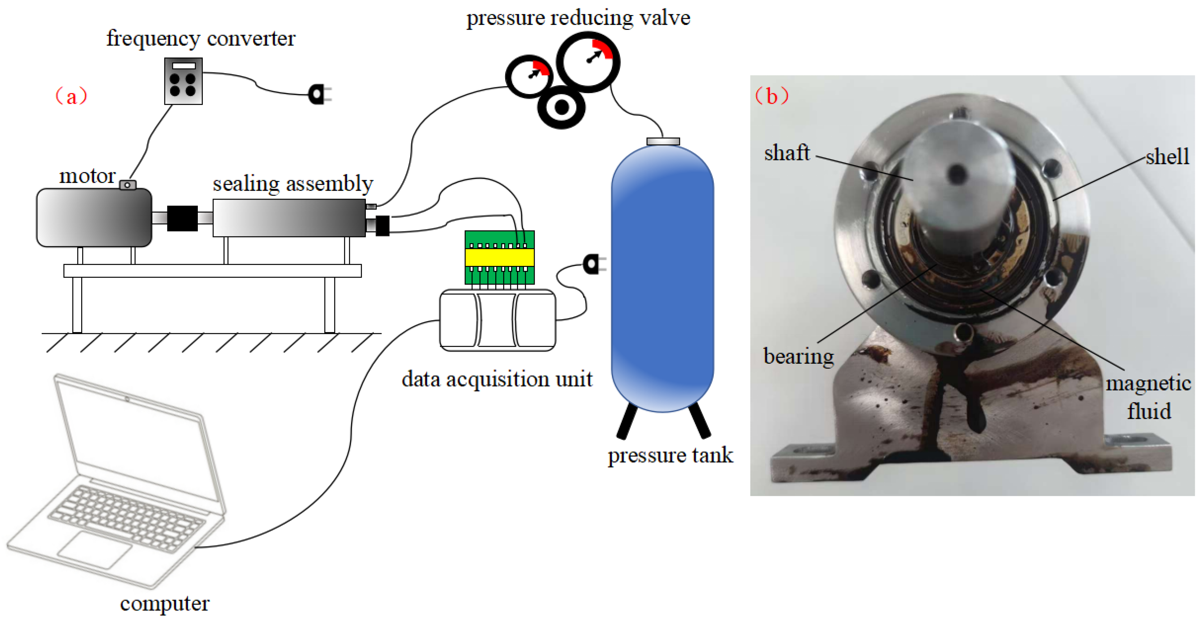
According to the test bench shown in Figure 22, the performance of the sealing device was tested. The connection methods of each component are as shown in Figure 23a. During the static sealing test, first disconnect the power supply of the motor, slowly adjust the pressure reducing valve knob, and slowly introduce gas (the sealing medium is air) into the sealing component from the pressure inlet. At the same time, observe the pressure changes displayed on the computer in the sealing chamber. As the inlet pressure slowly increases, the pressure displayed on the computer steadily rises. When the pressure drops sharply, the magnetic fluid and the sealing medium are ejected from the end of the sealing component on the motor side (as shown in Figure 23b), then turn off the gas source. At this time, the pressure value recorded on the computer is the static sealing pressure. When sealing with liquid, first fill the sealing cavity with tap water through the pressure inlet. When the tap water in the sealing cavity overflows, insert the gas source interface into the quick-change connector of the pressure inlet. The subsequent test steps are the same as the gas sealing test. During the dynamic sealing test, the frequency converter is first turned on to adjust the motor speed to 500 rpm. Once the motor speed stabilizes, the pressure regulating knob of the pressure reducing valve is adjusted to slowly apply pressure to the sealing component chamber. The subsequent method is the same as that of the static sealing test.

4.3. Analysis of Test Results

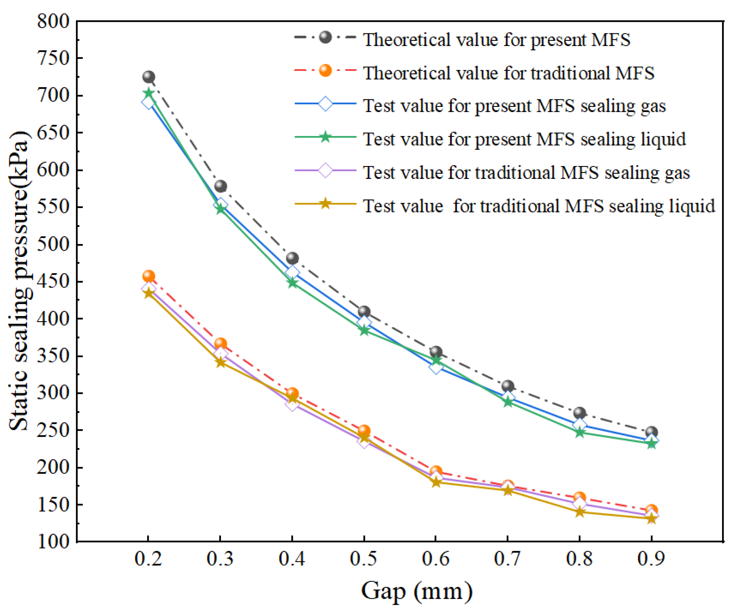
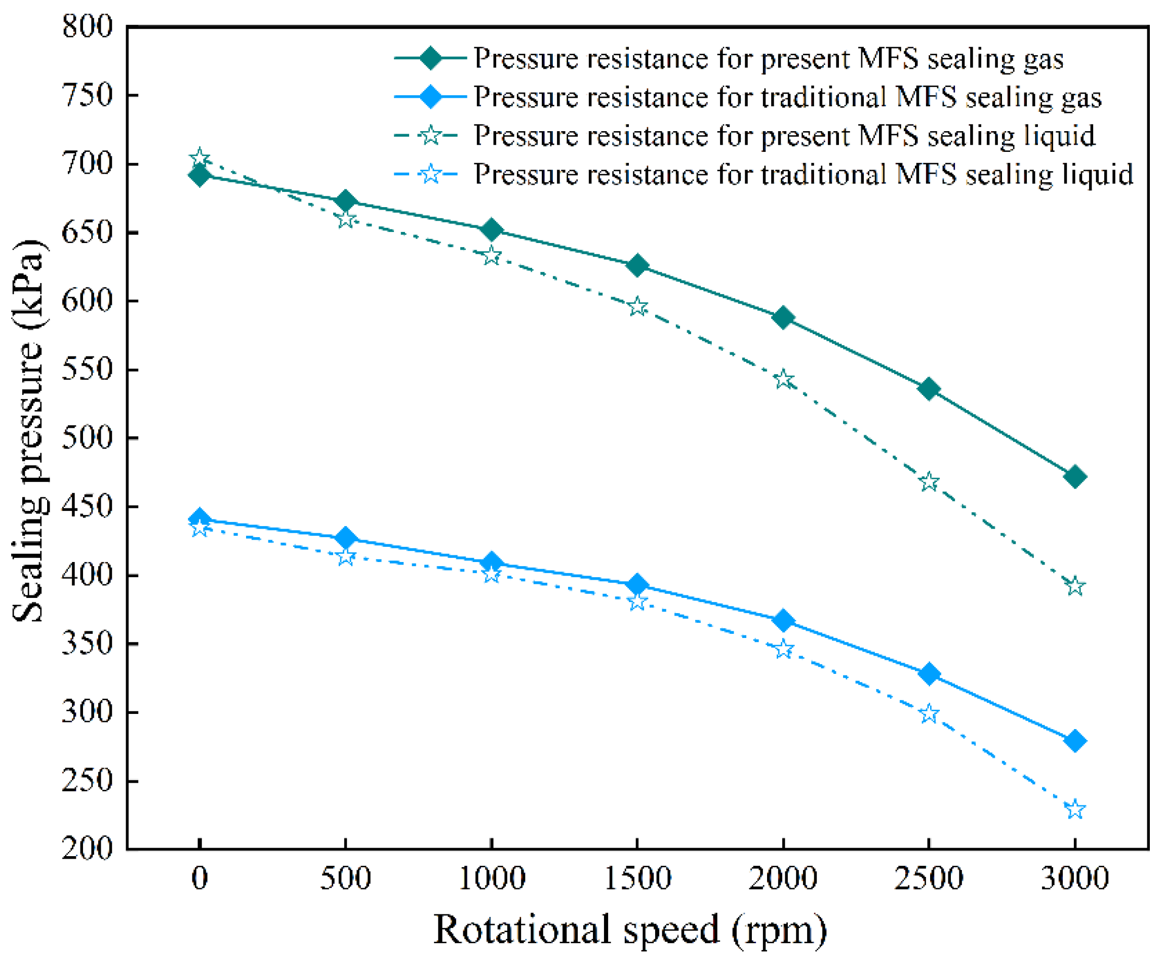
According to the above experimental method, the static sealing pressure under different sealing gaps and the dynamic sealing pressure under different rotational speeds were tested. The test results are shown in Figure 24 and Figure 25, respectively.
As can be seen from Figure 24, both the theoretical sealing pressure calculated by the numerical simulation and the sealing pressure measured in the experiment decrease gradually with the increase of the sealing gap. Moreover, the curves of their changes with the sealing gap are quite similar. The maximum error between the numerical simulation results of present MFS and the experimental values is approximately 6.9%, while that of traditional MFS is 7.5%. The possible reasons might be the processing and installation errors of the pole shoes and the fact that this device is a metal component with an invisible internal structure. During the injection of the magnetic fluid, the injection is not uniform between the teeth of each pole, which affects the test results. From the figure, it can also be observed that when the sealing gap is 0.2 mm, the sealing pressure is the maximum, and the maximum sealing pressure measured in the present MFS test is 704 kPa, while that of traditional MFS is 441 kPa. When the sealing gap is 0.9 mm, the sealing pressure is the minimum, and the minimum sealing pressure measured in the present MFS test is 233 kPa, while that of traditional MFS is 132 kPa. Both present MFS and traditional MFS show a significant decrease in sealing pressure as the sealing gap increases, with the decrease rates being 66.9% and 70%, respectively. Therefore, when designing the magnetic fluid sealing structure, it is advisable to avoid designing with a large gap. In addition, from the figure, it can be seen that the sealing pressure curves of the two sealing structures intersect when sealing gas and liquid, indicating that the sealing performance of the magnetic fluid seal is not significantly different when performing static sealing.
Figure 25 shows the pressure change curves of sealing pressure at different rotational speeds. The sealing pressure of the present MFS and the traditional MFS progressively drops with an increase in rotating speed, regardless of whether they are sealing gas or liquid, as the figure illustrates. When sealing gas, the sealing pressure of the present MFS is 692 kPa at 0 rpm, and the sealing pressure is 472 kPa at 3000 rpm, the sealing pressure decreases by 31.8%. While the sealing pressure of the traditional MFS is 441kpa when the speed is 0 rpm and 279 kPa when the speed is 3000 rpm; the sealing pressure has decreased by 36.7%. When sealing the liquid, the sealing pressure of the present MFS is 704 kPa at 0rpm and 392 kPa at 3000 rpm, which is a 44.3% decrease in sealing pressure. While the sealing pressure of the traditional MFS is 435 kPa at 0 rpm and 229 kPa at 3000 rpm, the sealing pressure decreases by 47.4%. The same structure shows a smaller decrease in performance when sealing gas compared to sealing liquid due to the influence of rotational speed. This indicates that the performance of the magnetic fluid sealing structure is superior when sealing gas compared to sealing liquid. Additionally, as can be seen from the figure, at the same rotational speed, the sealing pressure of the present MFS is significantly higher than that of the traditional MFS. When sealing gas, the sealing pressure of the present MFS reaches up to 1.69 times that of the traditional MFS, and when sealing liquid, it reaches up to 1.71 times. There are two main factors that produce these phenomena: firstly, the present MFS expands the inner permanent magnet and inner pole shoe construction on the rotor shaft side, thereby decreasing the magnetic leakage phenomenon of the traditional structure and enhancing the pole shoe’s capacity to gather magnetism; secondly, the addition of the inner permanent magnet enhances the magnetic flux of the entire magnetic circuit of the present MFS structure, thereby enabling the magnetic fluid in the sealing gap to be more firmly confined by a stronger magnetic field force and thus capable of withstanding greater sealing pressure.

5. Conclusions

This work presents the design of a magnetic fluid sealing device featuring a dual magnetic source, and the following are the key findings:
(1) Through experiments, the sealing performance of MFS is not significantly different when used for static sealing of gases and liquids. This is mainly because during static sealing, on the one hand, the magnetic fluid is not subject to the effect of centrifugal force, which would cause the magnetic fluid in the sealing gap to be flung out, reducing the sealing performance; on the other hand, during static sealing, no frictional power loss is generated in the sealing gap, which would produce heat and affect the performance of the magnetic fluid, thereby leading to a decrease in sealing pressure.
(2) Through experiments, it was verified that as the rotational speed increased, the pressure of the MFS gradually decreased. Moreover, the influence of the increase in rotational speed on the sealed gas was smaller than that on the sealed liquid. This is mainly because, as the rotational speed increases, the interface fluctuations and interface fusion between the magnetic fluid and the liquid medium intensify, which affects the performance of the magnetic fluid and leads to a decline in the sealing performance of the magnetic fluid.
(3) The sealing device designed in this paper has improved its sealing performance. However, due to issues such as test costs, the verification scope is only applicable to laboratory research and does not conduct more systematic tests on factors such as durability and heat generation during rotation. Additionally, this device has a relatively small overall size and is relatively easy to process and install, so it has a promising application prospect in medium and high pressure sealing environments with small shaft diameters. However, in engineering applications with large shaft diameters, the disadvantages of processing and installation need to be considered.

Author Contributions

Conceptualization, J.Q. and Z.L.; methodology, J.Q. and Z.L.; software, J.Q. and L.C.; validation, J.Q., C.C., L.C. and C.S.; formal analysis, J.Q. and Z.L.; investigation, C.C. and C.S.; resources, Z.L.; data curation, J.Q.; writing—original draft preparation, J.Q.; writing—review and editing, Z.L. and J.Q.; visualization, C.C.; supervision, C.C. and C.S.; project administration, Z.L.; funding acquisition, Z.L. All authors have read and agreed to the published version of the manuscript.

Funding

This research was funded by [Qinghai Provincial Basic Research Program Project] grant number [2024-0302-ZJC-0240].

Institutional Review Board Statement

Not applicable.

Informed Consent Statement

Not applicable.

Data Availability Statement

The data are contained within the article.

Conflicts of Interest

The Author Chuanshi Cheng was employed by China Yangtze River Power Co., Ltd., the author Changrong Shen was employed by East route of South-to-North Water diversion Jiangsu Water Resources Co., Ltd., the author Lin Cai was employed by Gongzui Hydropower General Plant of Guoneng Dadu River Company. The authors declare no conflict of interest.

References

  1. Khan, N.; Katiyar, A.; Nandi, T.; Abhyankar, A.; Eswara Prasad, N. Tunable thermal conductivity and rheology of in-house synthesized Fe55Co25Ni20 complex fluids under the external magnetic field. J. Mol. Liq. 2019, 294, 111662. [Google Scholar] [CrossRef]
  2. Li, W.; Li, Z.; Han, W.; Wang, Y.; Zhao, J.; Zhou, J. Morphologic transformation of ferrofluid during micropump driving under field control. Ann. N. Y. Acad. Sci. 2025, 1543, 194–203. [Google Scholar] [CrossRef]
  3. Yamasaki, H.; Kishimoto, T.; Tazawa, T.; Yamaguchi, H. Dynamic behavior of gas bubble detached from single orifice in magnetic fluid. J. Magn. Magn. Mater. 2020, 501, 166446. [Google Scholar] [CrossRef]
  4. Li, W.; Li, Z.; Han, W.; Li, R.; Zhang, Y. Mechanism of bubble generation in ferrofluid micro-pumps and key parameters influencing performance. Powder Technol. 2025, 467, 121562. [Google Scholar] [CrossRef]
  5. Mitamura, Y.; Sekine, K.; Okamoto, E. Magnetic fluid seals working in liquid environments: Factors limiting their life and solution methods. J. Magn. Magn. Mater. 2020, 500, 166293. [Google Scholar] [CrossRef]
  6. Radionov, A.; Podoltsev, A.; Peczkis, G. The specific features of high-velocity magnetic fluid sealing complexes. Mech. Adv. Technol. 2018, 2, 57–63. [Google Scholar]
  7. Trbušić, M.; Goričan, V.; Beković, M.; Jesenik, M.; Trlep, M.; Hamler, A. An experimental study on magnetic field distribution above a magnetic liquid free surface. J. Magn. Magn. Mater. 2020, 509, 166903. [Google Scholar] [CrossRef]
  8. Guo, Y.; Li, D.; Zang, G.; Qi, Z.; Zhang, Z. Research on a large diameter magnetic fluid seal with thin-wall parts. Front. Mater. 2022, 9, 932662. [Google Scholar] [CrossRef]
  9. Li, X.; Fan, X.; Li, Z.; Zhu, M. Failure mechanism of magnetic fluid seal for sealing liquids. Tribol. Int. 2023, 187, 108700. [Google Scholar] [CrossRef]
  10. Szczęch, M. Magnetic fluid seal critical pressure calculation based on numerical simulations. Simulation 2020, 96, 403–413. [Google Scholar] [CrossRef]
  11. Urreta, H.; Aguirre, G.; Kuzhir, P.; Lopez de Lacalle, L. Seals based on magnetic fluids for high precision spindles of machine tools. Int. J. Precis. Eng. Manuf. 2018, 19, 495–503. [Google Scholar] [CrossRef]
  12. Yang, X.; Shi, M.; Guan, Y.; Li, D. Numerical and experimental study of convergent integral embedded magnetic fluid seal. J. Magn. Magn. Mater. 2023, 570, 170522. [Google Scholar] [CrossRef]
  13. Li, W.; Li, Z.; Han, W.; Tan, S.; Yan, S.; Wang, D.; Yang, S. Time-mean equation and multi-field coupling numerical method for low-Reynolds-number turbulent flow in ferrofluid. Phys. Fluids 2023, 35, 125145. [Google Scholar] [CrossRef]
  14. Zhou, W.; Su, H.; Liu, H.; Zhang, Y.; Qiu, N.; Gao, B. Leakage and rotordynamic performance of a semi-Y labyrinth seal structure for centrifugal pump based on multi-frequency whirl method. J. Eng. Gas Turbines Power 2025, 147, 101022. [Google Scholar] [CrossRef]
  15. Li, D.; Li, Y.; Li, Z.; Wang, Y. Theory analyses and applications of magnetic fluids in sealing. Friction 2021, 11, 1771–1793. [Google Scholar] [CrossRef]
  16. Rosensweig, R.E. Buoyancy and stable levitation of a magnetic body immersed in a magnetizable fluid. Nature 1966, 210, 613–614. [Google Scholar] [CrossRef]
  17. Chen, Y.; Li, D.; Zhang, Y.; Li, Z.; Zhou, H. The influence of the temperature rise on the sealing performance of the rotating magnetic fluid seal. IEEE Trans. Magn. 2020, 56, 4600510. [Google Scholar] [CrossRef]
  18. Parmar, S.; Ramani, V.; Upadhyay, R.V.; Parekh, K. Two stage magnetic fluid vacuum seal for variable radial clearance. Vacuum 2020, 172, 109087. [Google Scholar] [CrossRef]
  19. Li, W.; Li, Z.; Wang, Z.; Wu, F.; Xu, L.; Peng, S. Turbulence intensity characteristics of a magnetoliquid seal interface in a liquid environment. Coatings 2021, 11, 1333. [Google Scholar] [CrossRef]
  20. Zhang, T.; Li, D.; Li, Y. Design and Optimization of Combined Magnetic Fluid Seal and Labyrinth Seal. J. Mech. Eng. 2022, 58, 172–181. [Google Scholar]
  21. Wang, H.; He, X.; Gao, Z.; Xu, X. Performance of Combined Magnetic Fluid Seal and Spiral Seal for Sealing Water. Chin. J. Vac. Sci. Technol. 2022, 42, 809–814. [Google Scholar]
  22. Chen, J.; Guan, Y.; Xu, W.; Zhang, T. Structural design and parameter analysis of a modular magnetic fluid rotary seal for robot joints. Vacuum 2023, 212, 112037. [Google Scholar] [CrossRef]
  23. Jiang, Y.; Chen, Y.; Lv, L.; Lu, J.; Li, D..; Zhou, H. Multi-parameter optimization of ferrofluid seal pole teeth based on magnetic-flow coupling and taboo genetic algorithm. J. Magn. Magn. Mater. 2023, 587, 171364. [Google Scholar] [CrossRef]
  24. Yang, X.; Xia, Y.; Huang, G. Numerical analysis and orthogonal optimization design of magnetic fluid reciprocating seals. J. Magn. Magn. Mater. 2024, 592, 171782. [Google Scholar] [CrossRef]
  25. Liu, L.; Li, D.; Li, L.; Wei, Y.; Li, Q.; Qi, Z. Design and study of sealing performance for ultra-clean and highly reliable magnetic fluid seals. Tribol. Int. 2025, 213, 111091. [Google Scholar] [CrossRef]
  26. Li, D. Theory and Application of Magnetic Liquid Sealing; Science Press: Beijing, China, 2010. [Google Scholar]
  27. Rosensweig, R. Magnetic fluids. Annu. Rev. Fluid Mech. 1987, 19, 437–461. [Google Scholar] [CrossRef]
  28. Chi, C. Fundamentals of Physics and Applications of Ferrofluid; Beihang University Press: Beijing, China, 2011. [Google Scholar]
  29. Yang, X.; Liu, G.; Li, Y.; Gao, S. Structural optimization of reciprocating seal with magnetic fluid based on orthogonal test design. J. Magn. 2021, 26, 229–237. [Google Scholar] [CrossRef]
  30. Li, Z.; Yuan, Z.; Li, X.; Wang, M.; Zhu, G. Research on dynamic coupling characteristics of magnetic fluid and gas medium interface in sealing devices. Phys. Fluids 2023, 35, 062004. [Google Scholar] [CrossRef]
  31. Li, Z.; Zhu, G.; Li, X.; Li, W.; Wang, Z.; Yuan, Z. Experimental visualization of the lifetime and self-healing of magnetic fluid seals. Vacuum 2023, 216, 112399. [Google Scholar] [CrossRef]
Figure 1. Diagrammatic schematic of the MFS. (a) The traditional sealing structure; (b) the present sealing structure.
Actuators 14 00561 g001
Figure 2. Distribution diagram of MFS under a certain pressure.
Actuators 14 00561 g002
Figure 3. The structural model of the magnetic fluid sealing device. (a) the present magnetic fluid sealing structure; (b) the traditional magnetic fluid sealing structure; (c) the composition of the magnetic fluid sealing device: 1—outer pole shoe, 2—magnetic fluid replenishment port, 3—outer permanent magnet, 4—bearing, 5—shell, 6—inner permanent magnet, 7—inner pole, 8—magnetic isolation ring, 9—shaft, 10—bearing end plate.
Actuators 14 00561 g003
Figure 4. 2D axisymmetric model (1—shaft, 2—short inner pole shoe, 3—short outer pole shoe, 4—long outer pole shoe, 5—long inner pole, 6—outer permanent magnet, 7—polar tooth, 8—inner permanent magnet).
Actuators 14 00561 g004
Figure 5. The magnetization curve and hysteresis loop of 2Cr13.
Actuators 14 00561 g005
Figure 6. Preliminary preparation before simulation calculation: (a) model meshing; (b) verification of grid-independence.
Actuators 14 00561 g006
Figure 7. Magnetic flux density distribution.
Actuators 14 00561 g007
Figure 8. Distribution of the initial structure’s magnetic flux density.
Actuators 14 00561 g008
Figure 9. Magnetic flux density cloud image at different sealing gaps.
Actuators 14 00561 g009
Figure 10. Magnetic flux density distribution for different sealing gaps.
Actuators 14 00561 g010
Figure 11. Sealing pressure for different sealing gaps.
Actuators 14 00561 g011
Figure 12. Magnetic flux density cloud image at different inner pole tooth heights.
Actuators 14 00561 g012
Figure 13. Magnetic flux density distribution for different pole tooth heights.
Actuators 14 00561 g013
Figure 14. Sealing pressure magnitude for different pole tooth heights.
Actuators 14 00561 g014
Figure 15. Cloud view of magnetic field distribution at different angles.
Actuators 14 00561 g015
Figure 16. Magnetic flux density distribution for different chamfer angles.
Actuators 14 00561 g016
Figure 17. Sealing pressure magnitude for different chamfer angles.
Actuators 14 00561 g017
Figure 18. Cloud view of magnetic field distribution at different eccentricity distances.
Actuators 14 00561 g018
Figure 19. Magnetic flux density distribution for different eccentric distances.
Actuators 14 00561 g019
Figure 20. Sealing pressure magnitude for different eccentric distances.
Actuators 14 00561 g020
Figure 21. Comparison of magnetic flux density on the 2D intercept line before and after improved structure.
Actuators 14 00561 g021
Figure 22. MFS test rig (1—motor, 2—coupling, 3—sealing assembly, 4—pressurized port, 5—pressure sensor, 6—pressure reducing valve, 7—computer, 8—data acquisition unit, 9—frequency converter).
Actuators 14 00561 g022
Figure 23. The illustration of the test device and test results: (a) experimental schematic diagram; (b) sealing leakage diagram.
Actuators 14 00561 g023
Figure 24. Static sealing pressure under different sealing gaps.
Actuators 14 00561 g024
Figure 25. Sealing pressure at different speeds.
Actuators 14 00561 g025
Table 1. Initial model structure parameters.
Sealing Gap
c
Inner Pole Tooth Height hAngle
α
Eccentricity Distance bRadius of Shaft
r
0.2 mm1 mm30°0 mm15 mm
Table 2. Experimental device-specific parameters.
NumberInstrumentManufacturerModelRangePrecision
1MotorJINYINGYVF2-71M300–3000 rpmN/A
2Pressure-reducing valveLightinglokR210~2500 kPaLevel 1.6
3Pressure sensorYBPCMPCM3000~1600 kPaLevel 0.25
4Data acquisition unitNI USB-6211//
5Frequency converterSHZKZK8800~0.75 kWLevel 0.5
Disclaimer/Publisher’s Note: The statements, opinions and data contained in all publications are solely those of the individual author(s) and contributor(s) and not of MDPI and/or the editor(s). MDPI and/or the editor(s) disclaim responsibility for any injury to people or property resulting from any ideas, methods, instructions or products referred to in the content.