1. Introduction
As a miniature instrument in pump technology and an important component of microfluidic technology, the micropump is a key device in micro-electro-mechanical systems (MEMS) [
1,
2]. It holds significant importance in application fields such as the medical field, microfluidic manipulation, energy conservation and environmental protection, chemical engineering, aerospace, and electronic cooling [
3,
4,
5,
6]. The design and application of intelligent propulsion and magnetic fluid micropumping devices across multiple fields, driven by new industrialization trends [
7,
8], are placing higher demands on the performance and functionality of micropumps. Under these high demands, traditional micropumps expose shortcomings such as a complex structure, high energy consumption, high driving voltage, difficulty in miniaturization, susceptibility to fluid leakage, poor biocompatibility, and high manufacturing costs [
9,
10,
11,
12,
13]. These demands encompass not only structural simplification, high integration, precision, and intelligence but also the ability of micropumps to deliver a wider range of flow rates to meet varying operational demands [
14,
15,
16]. In this context, the ferrofluid micropump (FFMP) has become an important research direction in micropump technology due to its numerous advantages, such as simple structure, ease of integration, zero friction, self-sealing, and convenient motion control, demonstrating extremely broad application prospects and significant development potential.
Ferrofluid micropumps originated from interdisciplinary research in ferrohydrodynamics and microfluidics, leading to many emerging directions [
17]. In 1987, D.S. Spencer et al. [
18] pioneered a groundbreaking MEMS micropump specifically designed for the biomedical field. Since then, micropumps have gradually become key components in MEMS technology and microfluidic systems, playing an increasingly important role. In 2001, Anson Hatch et al. [
19] experimentally studied a pump that used an MF to push fluid through a microchannel. This micropump′s pumping relied on a magnetically driven ferrofluid plug, and a circular flow channel design demonstrated continuous pumping by regenerating a translating ferrofluid plug at the end of each pumping cycle. In 2010, Hiroshige Kumamaru et al. [
20] experimentally studied a micropump with reciprocating motion and a diffuser acting as a valve, where diffusers with different divergence angles were used for unidirectional water pumping. In 2012, Chia-Yen Lee et al. [
21] proposed an experimental micropump with a pumping performance that can be adjusted by adjusting the Rev. The pumping results were compared for two different settings: orthogonal and tangential inlet/outlet channels. The experimental results showed that the tangential microchannel had lower pipeline loss, and the flow rate of the tangential micropump was slightly higher than that of the orthogonal micropump at a constant rotational speed. In 2023, Wangxu Li et al. [
22,
23,
24] conducted an in-depth mechanism analysis on the pumping mechanism, bubble generation, and magnetic fluid of micropumps in microscopic fields, which has played a positive role in the research of magnetic fluid micropumps. In 2024, Wang Ye et al. [
25] pioneered a dual-rotating-magnet-actuated ferrofluidic micropump, grounded in fundamental ferrofluid dynamics. Our findings demonstrate a marked augmentation in the magnetic coupling force due to the dual sources. An investigation into failure modes pinpointed the root cause: the initiation of foam at the plug′s rear and its subsequent propagation resulted in the eventual breakdown of the plug’s integrity. The velocity and MF strength of the ferrofluid plug are critical factors affecting this process. In the same year, Wang Ye et al. [
26] designed an experimental micropump. They designed a new type of blade structure, consisting of magnetic fluid blades, which can improve the pumping performance of a micropump and, to some extent, enhance pumping reliability and stability. Based on the aforementioned research results, in this study, to meet the demands of diverse application scenarios, a pioneering neodymium magnet ball plug micropump was developed. This is a structural improvement on the classic annular pump chamber ferrofluid micropump. This design can effectively enhance the self-sealing pressure resistance and specific surface area, which helps to improve performance, with measurable enhancements observed in the maximum pumping height and volumetric flow rate of the pump. The system can improve its pumping stability.
With the rapid technological development in recent years, ferrofluid micropumps have been evolving towards high stability, high integration, high pumping flow rate, and the ability to withstand high suction pressures. However, existing technologies cannot meet the demands for large flow rates and high back pressures, and existing technologies still have significant shortcomings in dealing with high flow and high pumping height tasks. Based on this, this study combines the motion and mechanism of magnetic fluids with the sealing method of water pumps [
27] to design a magnetic fluid micropump using neodymium magnetic balls as dynamic sealing units. The proposed micropump in this study exhibits significant advantages compared to traditional micropumps or magnetic fluid plug schemes. The proposed micropump has a high flow output, achieving a maximum pumping flow rate of up to 4043.86 μ L/min, far exceeding similar micropumps (such as the 1 mm specification of 2046.2 μ L/min), providing strong power for applications that require rapid liquid transport. The micropump successfully achieved a pumping height of up to 111 mm, demonstrating its strong pressure output capability and ability to overcome significant fluid resistance and meet multi-channel, long-distance, or vertically upward pumping needs. After introducing neodymium magnetic ball plugs, the pumping stability of the micropump was significantly improved. Magnetic balls provide a more stable structural support for magnetic fluids, reducing the risk of failure under complex working conditions and ensuring long-term reliability. By simply adjusting the size of the neodymium magnetic ball (i.e., changing the diameter ratio α), the performance characteristics of the micropump can be flexibly customized. The scheme of combining solid neodymium magnetic spheres with magnetic fluids cleverly utilizes the strong magnetism of neodymium magnets, which not only enhances the driving ability of the magnetic fluid plug but also improves the robustness of the seal through the physical structure. This is an innovative technological breakthrough that differs from traditional designs. To check the effectiveness of the new configuration, a dedicated experimental testing system was also established in this work to analyze the flow rate and maximum pumping height of the micropump with performance experiments. With the unique advantages mentioned above, this micropump has broad application prospects in multiple cutting-edge fields. In targeted drug delivery and continuous drug infusion systems, it can provide precise and stable flow rate control to ensure drug efficacy. Advanced electronic device heat dissipation and cooling systems are particularly suitable for next-generation microchannel cooling systems, providing powerful liquid heat dissipation for high-power density chips, such as CPUs and GPUs. Its high head capability is sufficient to push the coolant through dense and tortuous microchannel radiators. In high-throughput screening that requires parallel processing, such as drug development and combinatorial chemistry, micropumps of different specifications can be configured according to different flux and pressure requirements, achieving flexible and efficient fluid manipulation. The stable operational capability of 1 mm micropumps in portable and wearable devices at high speeds makes them ideal for integration into devices that are sensitive to volume and power consumption, such as portable chemical analyzers, intelligent wearable health monitoring devices, etc.
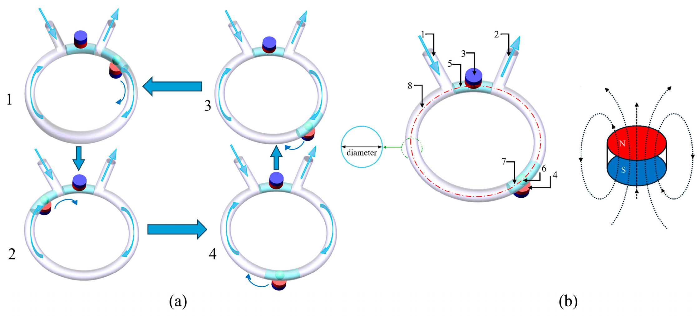
Below is an explanation of the principle of the micropumping device used in this study. The motion pump scanning process of the pump is shown in
Figure 1. The pumping device was initially in an inactive state. The fixed PM is seated above the middle of the two ports of the micropump, while the non-fixed PM is seated below the middle of the two ports. The lower permanent magnet attracts the neodymium magnetic ball and the ferrofluid, forming a ferrofluid plug to achieve separation between the inlet and outlet. It can self-lock without consuming electrical energy or other energy sources. During micropump operation, the motor drives the rotating permanent magnet to rotate. As the rotating permanent magnet gradually moves away from its initial position, the neodymium magnetic ball ferrofluid plug is attracted and pulled out, as shown in
Figure 1a. As the motor rotates, the ferrofluid plug pushes the pumped liquid out through the outlet channel, as shown in 1 and 2 of
Figure 1a. When the ferrofluid plug approaches the initial position again, the dynamic magnetic ball plug gradually merges with the initial static magnetic fluid under the influence of the MF, as shown in 4 of
Figure 1a. Throughout the entire pumping cycle, the magnetic fluid begins to separate and then reconform, repeating this process. The motor generates a certain torque through 12V DC electricity and then transmits the force to the dynamic magnetic ball plug through non-contact magnetic coupling under the influence of the MF. This mechanism avoids the use of unnecessary traditional mechanical transmission components and significantly simplifies the overall structure of microfluidic micropumping devices.
2. Numerical Calculation of the Neodymium Magnetic Ball Plug Ferrofluid Micropump
2.1. Physical Model
The construction of the neodymium magnetic ball plug ferrofluid micropump used in this study and the dimensions of the permanent magnets are displayed in
Figure 2 and represented in
Table 1. The pump chamber channel adopts a circular ring structure, which is more conducive to achieving the reciprocating circulation function of the micropumping device. The fixed permanent magnet (FPM) is placed above the static ferromagnetic fluid plug (SMP) of the annular micropump. A rotating permanent magnet (RPM) driven by a motor is placed below a dynamic ferromagnetic fluid plug (DEFP). Red represents the N direction, and blue represents the S direction.
DEFP starts to move uniformly through circular microchannels in a clockwise circular motion, which causes the MF inside the microchannels to exhibit periodic changes. In this experiment, the line connecting the center of the dynamic magnetic fluid plug and the center of the micropumping device is set as L1, and the line connecting the center of the static magnetic fluid plug and the center of the pumping device is set as L2. The angle between L1 and L2 is defined as the rotation angle, which is 0° at the initial motion of each experiment.
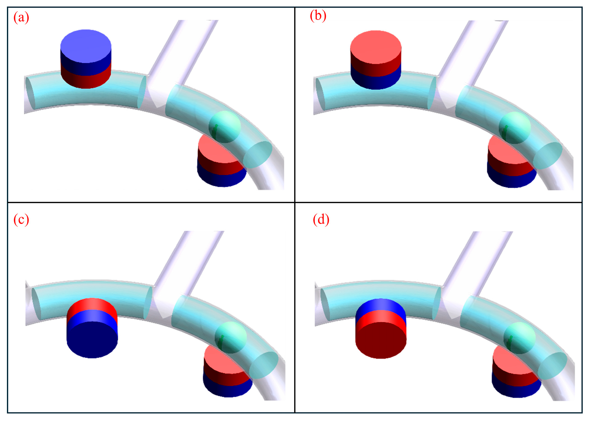
To study the sealing performance of the SMP and DEFP, two magnet placement modes, Model a and Model b, were set up according to the magnet placement, as shown in
Figure 3. The evaluation must consider not only the sealing performance but also the pumping performance of the device and the self-sealing capability of the dynamic and static ferrofluid plugs. Therefore, when deciding which magnet placement method to adopt, the orientation of the PM pole should also be in view. Based on the combinations, the two permanent magnets were arranged along different magnetic pole directions, resulting in four arrangement modes due to symmetry. You can observe the four different combinations of MFs in
Figure 4.
2.2. Mathematical Model
In the motion system of a magnetic fluid micropump, assuming that the magnetic fluid is uniform and not affected by pressure, the magnetic fluid can be regarded as a whole. We will represent the magnetic density
fm in the experiment as follows [
28]:
µ0 represents the vacuum permeability, M represents the magnetization, and H represents the MF intensity.
The comprehensive definition of the power of an MF is the expansion work. As magnetic energy is converted into kinetic energy, a portion of this energy is employed to magnetize the ferrofluid. Throughout the driving process of the FFMP, the external work executed by the DEFP can be described by the following expression [
29]:
In the field of fluids, following the expression of dimensionless numbers, viscous forces and interfacial forces are not limited by the characteristic size. Due to the interface effect being neglected, viscous forces dominate the flow, and it will also lose some energy. The fluid in the FFMP is assumed to be incompressible. In the micropump motion program, viscous losses occur between fluid layers and between the liquid and walls inside the pump. As the net magnetic force exceeds the force applied by the pressure gradient, DEFP will move in the orientation of the changing MF. Regarding this, the pressure gradient is expressed as follows [
19]:
pl and
pf represent the pressure loss due to the stickiness of the transported fluid and the pressure loss due to the viscosity of the ferrofluid, separately, η is the dynamic viscosity of the fluid, and
Qν is the volumetric flow rate.
a and
b are specific data of microchannels [
30]:
The relationship between volumetric flow rate
Qν and rotational speed
n is as follows:
Therefore, when pumping liquid under the action of the micropump, the energy provided by the dynamic magnetic fluid plug to the magnetic fluid is linearly related to its flow velocity. If a larger flow rate is needed, we need to study the speed of the micropump, the cross-sectional area of the pump chamber, and the size of the pump.
Due to its unique driving mode and the self-sealing characteristics of the fluid, the FFMP can maintain a certain back pressure, preventing backflow. Formula (7) [
31,
32] defines the maximum pressure withstand capability of the self-sealing. The sealing performance of magnetic fluid micropumps is determined by the
Ms and magnetic coupling performance.
Under ideal working conditions, in the selection of the ferrofluid suspension (FFMPS), optimizing the pump chamber structure can enhance the pumping capacity of FFMPS under a fixed magnetic moment (Ms). Enhancing the MF by altering the magnetic strength distribution strengthens the coupling capability between the permanent magnets and magnetofluids.
The magnetic flux density generated by the PM in the micropumping pipeline is confirmed by Gauss′s theorem for magnetism (8), where the external MF (
H) depends on the magnetic scalar potential (
Vm) [
33]:
Among them, µr is the relative magnetic permeability of the PM. Br is the residual magnetism of the magnet.
The pumping performance and pressure resistance of magnetic fluid micropumps will change due to the variation in the MF strength gradient of the magnetic fluid plug.
2.3. Numerical Calculation of MF Simulation
The rotating magnet moves circumferentially clockwise and uniformly within the circular micropipeline. The MF inside the microchannel will undergo regular changes along with circular motion. On the same plane, the angle formed by the line connecting the center of the rotating magnet and the center of the microchannel is defined as the rotation angle (θ) of the rotating magnet; at the beginning moment, θ = 0°. In the numerical calculation and analysis of the MF, the PM is NdFe30, with a coercivity of Hc = 837,999 A/m. The relative permeability of the ferrofluid is set to 1.04, the saturation magnetization Ms = 39.62 kA/m, and the calculated boundary condition is set to a zero tangential MF.
Without altering the fundamental configuration, the arrangement and precise positioning of the PMs play an important role in the formation the MF distribution within the microchannel. This study examines how two distinct permanent magnet configurations—denoted as type (a) and type (b) in
Figure 3—affect the magnetic environment inside the channel. Configuration (a) is referred to as “coaxial alignment”. In contrast, configuration (b), termed “non-coaxial alignment,” describes a setup in which the central magnetic axis may intersect the microchannel and its ferrofluid contents without following a centered path. MF numerical simulation analysis was carried out for micropump chambers with these two different permanent magnet placement modes.
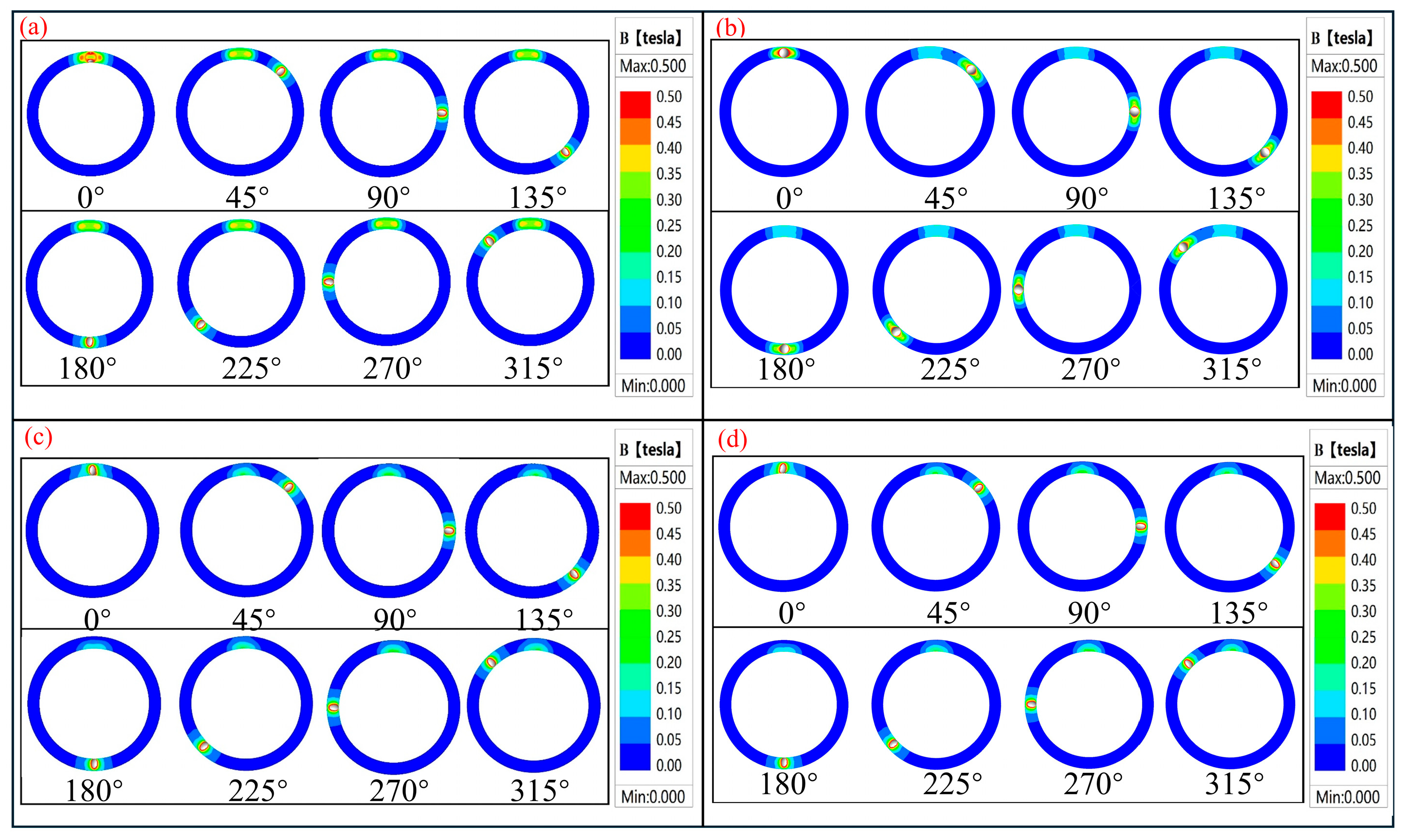
Figure 5 sequentially presents cloud diagrams of the magnetic flux density distribution within the micropipeline for every 45° increase in rotation angle.
Figure 5a,b show the magnetic field distribution cloud maps for four different PF placement modes. Among them, Mode I (
Figure 5a) has the largest overlap range,
Figure 5c has a slightly smaller overlap range, and the other two placement modes have a smaller overlap range. It can be observed that the magnetic regions composed by static and dynamic magnetohydrodynamic plugs have a large superimposed range only at positions close to θ = 0°, 45°, and 315°. In other areas, the two magnetic regions formed will not interfere with each other, just like the distribution curve in the figure below. For the SMP MF, its high magnetic flux density is concentrated on the outer side of the micropipeline, while the magnetic flux density is lower in the central region and on the inner side of the micropipeline. The elevated magnetic flux density within the MF in the DEFP area is predominantly localized along the inner periphery of the pump chamber conduit, whereas the central area and outer diameter exhibit comparatively lower flux density levels. This nonuniform distribution of magnetic flux density causes the failure pressure experienced by the ferrofluid in the microchannel at any instant to be unevenly distributed. Under high back pressure, this may lead to unilateral rupture of the ferrofluid, resulting in sealing failure. When severe, it can cause the ferrofluid plug to rupture, thereby contaminating the liquid in the pipeline. In summary, further research and discussion are needed to determine the optimal permanent magnet placement method.
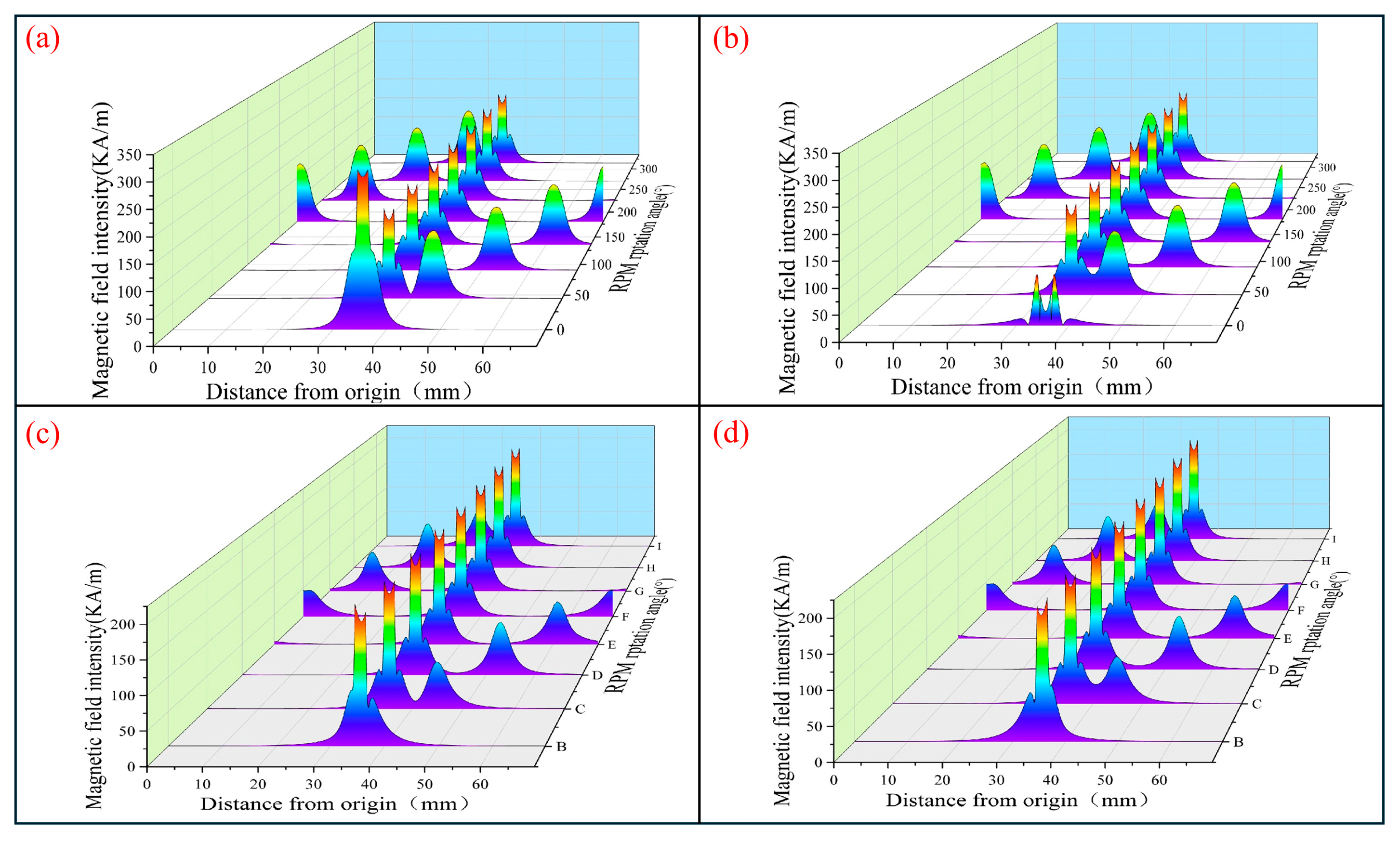
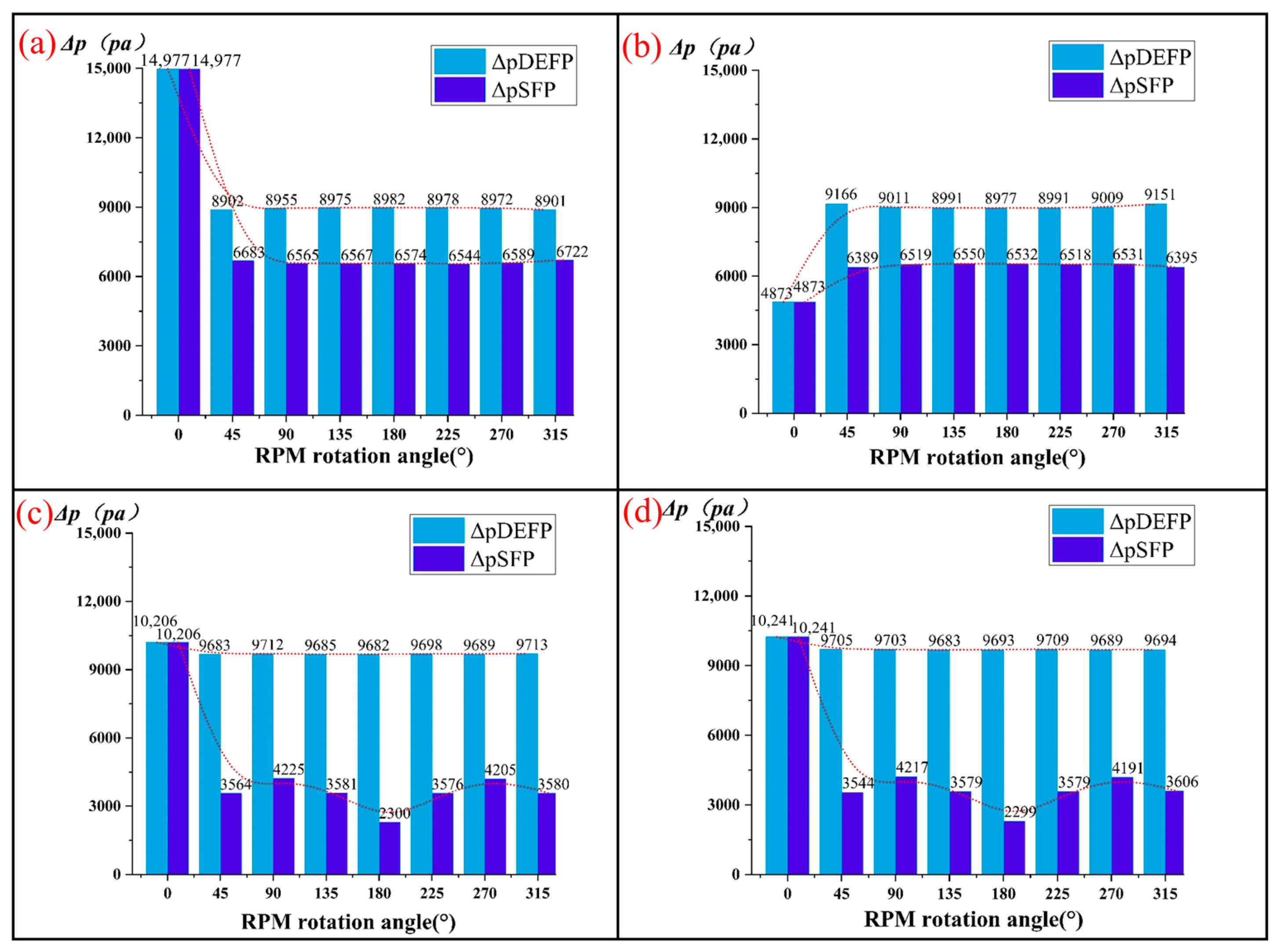
Numerical simulations of the MF for the above four placement modes at θ = 0–315° were conducted separately. Equation (7) was used to calculate and compare the maximum pressure resistance of self-sealing of the DEFP and SMP in the micropipeline. The resultant data are presented in
Figure 6, which illustrates the distribution of magnetic field intensity within the micropipeline.
Evidently, the MF strength profiles of the four configurations exhibit a broadly comparable pattern. At θ = 0°, the RPM and FPM assume symmetric positions, resulting in the strongest magnetic superposition effect, where the field intensity reaches its maximum. As the rotation angle increases, the two permanent magnets incrementally shift out of alignment, leading to a gradual reduction in magnetic superposition. The MF propelling the motion of the DEFP tracks the positional change of the RPM and propagates in the form of a traveling wave, which manifests as a one-dimensional wave phenomenon.
In this context, t and x denote time and position, respectively. Under ideal conditions, where f (x, t) equals zero, the rotating magnetic field remains largely constant during propagation. The average MF extent of FFMP under model a is about 1.5 times that under model b. The average MF extent of SMP in model a is 1.63 times that of model b, and the average MF extent of DEFP in model b is 1.08 times that of model a. In both FFMPs, due to the overlapping placement of the rotating magnets, there are also two peaks. Therefore, the fixed MF portion in the micropipeline presents a wider magnetization area. However, due to the different coverage directions of the fixed MF portion (FPM) and the rotating MF portion (RPM) relative to the ferrofluid plug, there are certain differences in the MF intensity of the two parts MF plug. For FFMP model a, the average MF intensity gradient ΔHavg at the DEFP position is about 1.4 times that of the SMP.
According to
Figure 7, in Mode I, the cloud map of the SMP MF is mainly distributed in the middle, a distribution characteristic that effectively enhances the MF throughout the entire device. Simultaneously, the overall intensity of the magnetic field within the DEFP increases substantially, with regions of moderate to high flux density predominantly concentrated in the central area. The uniform distribution of magnetic flux density makes the DEFP MF distribution even and concentrated, a characteristic beneficial for the pump to withstand higher reverse pump pressures.
As illustrated in
Figure 7, the red dashed line represents the trend of changes in selfsealing performance every 45 degrees, from 0-315 degrees. altering orientation and position of MF and orientation and position of the FPM has some effects on the sealing ability of ferrofluid in the microchannels. When the angle = 0°, the self-sealing and compressive performance of the SMP along orientation and position of MF III decreases by approximately 31.9%. Theoretically, the configuration of the rotating magnet′s magnetic field (MF) critically influences the sealing capacity of the magnetic fluid within the microchannel, particularly in systems actuated by rotating magnets. If the upper and lower magnets of the micropipeline are arranged with the same magnetic pole orientation, the MFs created by the two magnets will have identical polarity, resulting in partial cancellation and a consequent reduction in overall MF strength. Conversely, when the two magnets are arranged in opposite directions, the MFs produced exhibit completely opposite polarities. When superimposed in the MF region, the respective MFs cancel each other out, leading to a decline in the overall MF intensity.
This article conducts verification tests on the four permanent magnet placement modes through subsequent pumping test experiments and verifies them through data on pumping flow rate and maximum pumping height. In summary, to ensure the micropump has sufficient suction capacity and working back pressure, considering all the above factors, magnet placement Mode I was determined to be the optimal magnet placement method.
3. Neodymium Magnetic Ball Plug Ferrofluid Micropump System and Performance Testing
3.1. Experimental Test System for the Neodymium Magnetic Ball Plug Ferrofluid Micropump
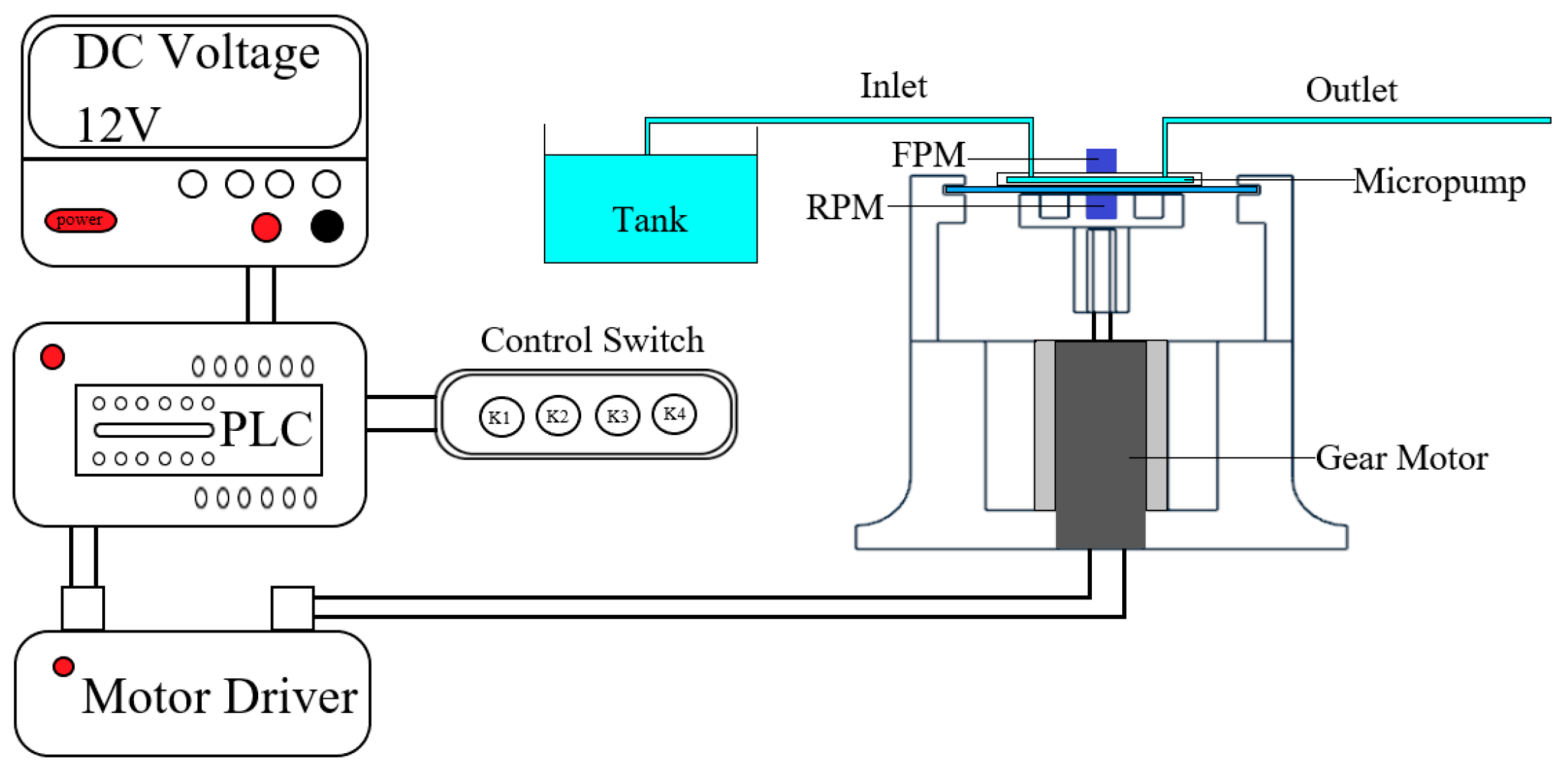
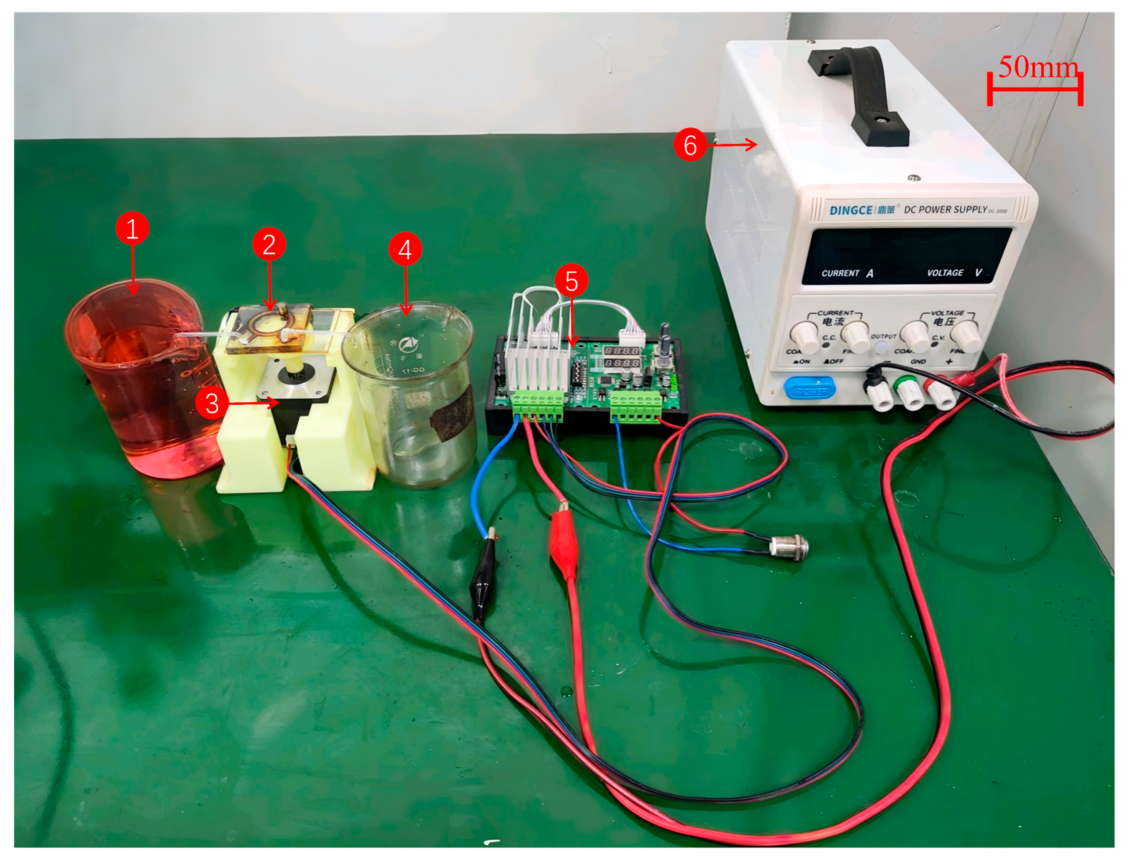
To evaluate the improvement effect of the pumping performance of the neodymium magnetic ball magnetic fluid micropump, this study conducted performance tests on the developed prototype, including the maximum pumping flow rate and maximum pumping height of the micropumping device. The prototype is prepared using CNC machining technology and made of polymethyl methacrylate (PMMA), which has the characteristics of good transparency, excellent biocompatibility, low cost, and convenient processing. In this experimental test, the ferrofluid used is a kerosene-based magnetic fluid, with mass fractions of solid magnetic particles of 5%, 10%, and 15%, respectively. A photograph of the CNC-machined prototype and the core experimental setup is provided in the figure. To avoid the infiltration of magnetic fluid into the outlet channel under pressure, a certain buffer space is left in the FPM to accommodate changes in the volume of the magnetic fluid. To precisely control the speed variation, the micropump is powered by a 42-step stepper motor with a planetary gearbox to support rotation. A PLC controls the movement of the motor and corresponding programs. The physical components are shown in
Figure 8. The microplatform bottom plate of the pumping device is equipped with a bracket for fixing the driving motor, and the top surface is designed with a groove for embedding and fixing neodymium magnets. Another set of rotating magnetic sources is installed in specially designed grooves. The specific experimental installation method and actual experimental assembly effect are shown in
Figure 9.
3.2. Pump Flow Rate Test
To test the pumping performance of a magnetic ball plug type magnetic fluid micropumping device, we designed three different diameters of neodymium magnetic balls for the experimental setup. The magnetic ball diameters (d) were 1 mm, 1.5 mm, and 2 mm. The experimental structural connection of the magnetic ball plug type magnetic fluid micropumping device is shown in
Figure 9, and the actual pumping device is shown in
Figure 10.
The ratio of the magnetic ball diameter
d to the pipe inner diameter
D is set as the pipe diameter ratio α:
During the measurement, the outlet and inlet were kept at the same height to eliminate the influence of gravitational potential energy on the pumping effect. The measurement of the container is obviously greater than the pipeline, so the height of the liquid surface in the container is considered constant during the proof. We tested the maximum pumping flow rate of FFMP under diverse diameters of magnetic balls and different rotational speeds. This micropumping device starts continuous pumping after startup and is tested when it stabilizes. Each test lasts for 2 min, and the experiment is repeated three times. The experimental data is then recorded and processed so as to calculate the average value. After weighing, it is tested according to Formula (12), where
Mg is the total mass,
Mc is the container mass,
ρ is the density of the pumped water, and
t is time:
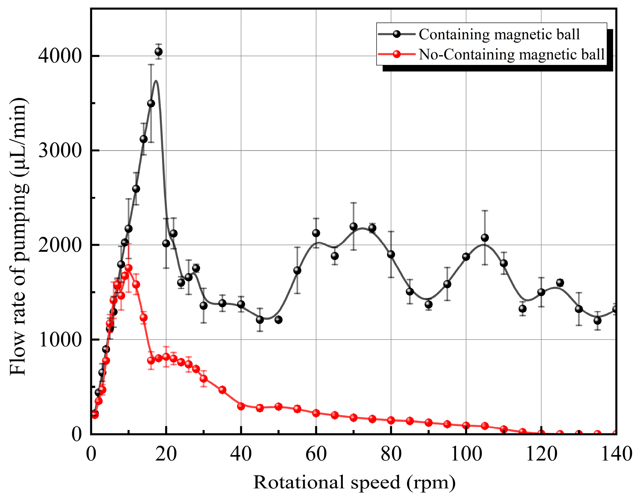
When the speed of all FFMPs increases to a certain value, the pumping performance of all FFMPs will decrease significantly. However, the 2 mm-FFMP operated stably at low speeds in the flow channel and operated smoothly at medium speeds, and under pressure, a layer of fine ferrofluid foam was observed. At high speeds, after the speed exceeded 25 rpm, ferrofluid was gradually pumped out of the pump′s outlet. Surface deposition of ferromagnetic fluid can be observed in the microchannels, accompanied by a decrease in optical permeability of the channel. After testing the 2 mm-FFMP at 145 rpm, the micropump was observed to be in a static state, and the ferrofluid was significantly reduced because the neodymium magnetic ball destroyed the seal of the ferrofluid plug at high speed, squeezing the ferrofluid and the pumped liquid out of the pump chamber. Accordingly, we also tested the pumping flow rate of a 2.2 mm-diameter micropump chamber without a neodymium magnetic ball for comparison, i.e., a comparison between α
0 = 0% and α
3 = 91%. The data is shown in
Figure 11.
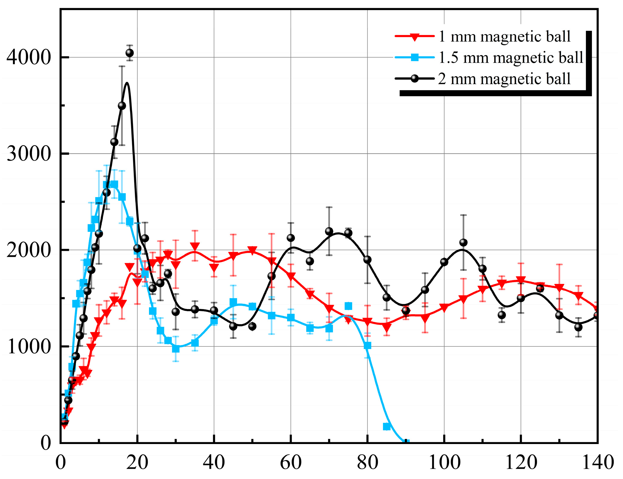
With the pump outlet height fixed equal to the inlet height, the relationship between pumping flow rate and motor speed for the N-FFMP (α0) generally shows a parabolic-like trend. However, the pumping flow rate of the 2 mm-FFMP (α3) did not tend towards 0 at higher speeds but fluctuated between 1400 and 2200 μL/min. To investigate this phenomenon and the aforementioned phenomenon of ferrofluid being squeezed out of the micropump chamber, the back pressure height of the two tested micropumps was measured. The testing method involved connecting a water pipe perpendicular to the pump chamber surface at the outlet of the micropump. The pipe diameter was the same as the outlet diameter of the micropump. The maximum back pressure height after the flow rate tests was measured. The back pressure height of the N-FFMP (α0) after the 145 rpm pumping test could still reach 30 mm, while that of the 2 mm-FFMP (α3) after the 145 rpm pumping test was 0 mm. The reason is that the ferrofluid in the pump chamber was significantly reduced, failing to achieve the sealing effect of the DEFP and SMP. Therefore, in subsequent experiments, only the 2 mm-FFMP (α3) micropump was tested for motor speeds ranging from 0 to 26 rpm, and tests above 26 rpm were no longer conducted. Consequently, the maximum operating speed for the 2 mm-FFMP (α3) was limited to 26 rpm, while its peak pumping flow rate of 4043.86 μL/min was achieved at 18 rpm; N-FFMP (α0) has a max feed rate of 120 rpm and a maximum micropump pumping flow rate of 10 rpm (1758.8 μL/min).
Experiments continued with two other groups having magnetic ball diameters of 1 mm and 1.5 mm, with pipe diameter ratios α1 = 45% and α2 = 68%, respectively.
As shown in
Figure 12, as the diameter of the neodymium magnetic ball inside the device pipe decreases, the maximum pumping flow rate of the micropump decreases, but the maximum speed increases. Regarding the 1 mm-FFMP (α
1), the maximum pumping flow rate was reduced to 2046.2 μL/min, corresponding to a speed of 35 rpm, and the maximum tolerable motor speed increased to 200 rpm. For the 1.5 mm-FFMP (α
2) micropump, the maximum pumping flow rate increased to 2685 μL/min, corresponding to a speed of 14 rpm, and the maximum tolerable motor speed increased to 90 rpm.
Although the 2 mm-FFMP (α3) has the lowest maximum tolerable motor speed of 25 rpm, inferior to other micropumps, due to its excellent pumping performance, it still achieved the highest flow rate among all micropumps, 4043.86 μL/min. The motor speed is 18 rpm.
The theoretical pumping flow value T per revolution for this micropumping device is tested according to the following formula:
where T is the theoretical pumping flow value per revolution, d is the pipe inner diameter, D
3 is the pump chamber inner diameter, and D
4 is the pump chamber outer diameter. The calculated T is approximately 239 μL. Let the ratio of the actual maximum pumping flow rate to the theoretical maximum pumping flow rate be β, i.e.,
Calculated using the above formula, β1, β2, and β3 under α1, α2, and α3 are 24.5%, 80.2%, and 94%, respectively. In summary, based on the relationship between the α and the maximum pumping flow rate, the larger the α, the larger the maximum pumping flow rate is. However, there is no clear relationship yet between the α and the maximum tolerable speed or the speed at maximum pumping flow rate. Based on the relationship between the α and the theoretical pumping flow rate, β increases as α increases.
3.3. Maximum Pumping Height (Maximum Back Pressure) Test
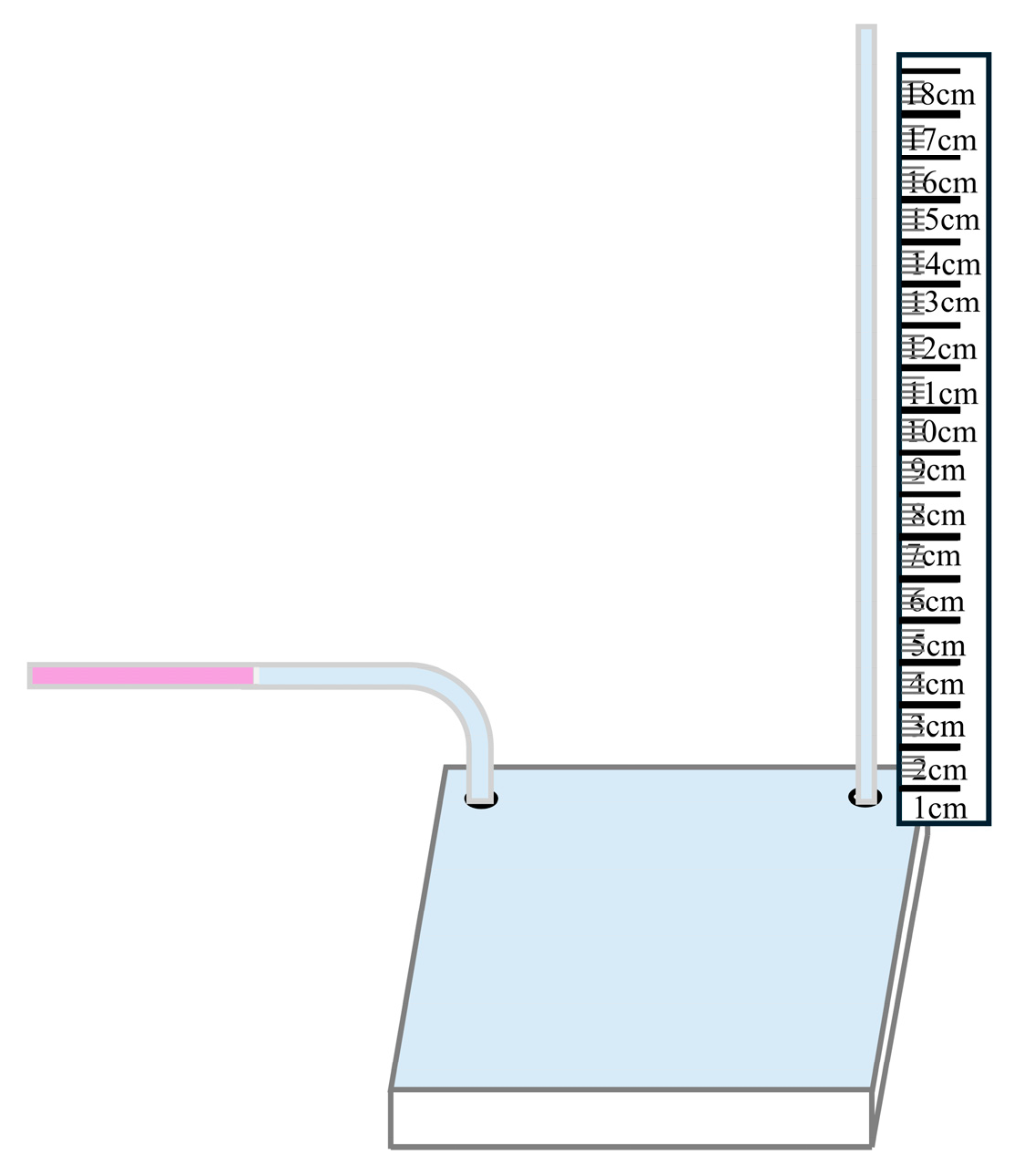
The ability of a micropump to overcome flow resistance is commonly known as back pressure. The pumped medium selected for measuring the micropump′s back pressure height is still water. The method for measuring back pressure height in this experiment is to measure the height difference of the water column between the micropump′s inlet and outlet. The measurement principle is similar to that in
Section 3.1, mainly using a vertical ruler measurement method to measure the back pressure height of the micropump, as shown in
Figure 13.
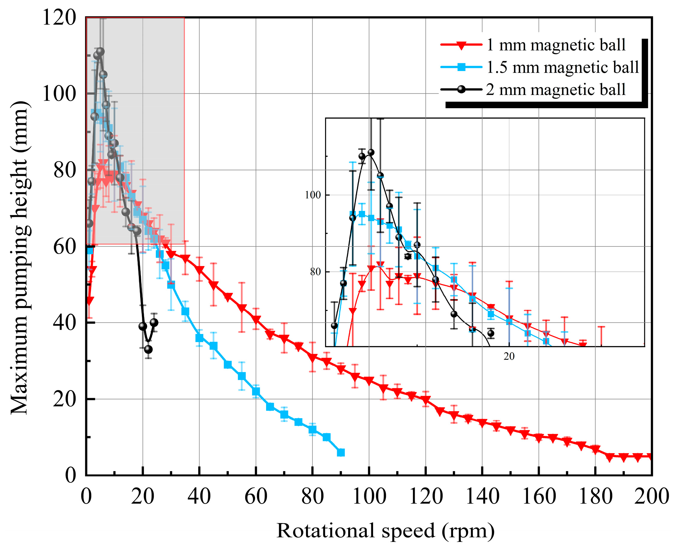
Based on the above principle, the measurement of the micropump′s back pressure began. After multiple repeated tests, the back pressure height at different stepper motor speeds was obtained through experimental testing. Due to the impact of some force majeure events, the pumping height fluctuates and eventually tends towards dynamic equilibrium. For accurate measurement, after adjusting the speed each time, the micropumping device ran continuously for 5 min to enter a stable state, and then, its average value was calculated through multiple measurements. According to
Figure 14, in the lower rotational speed region, the pumping height of the device increases with the enhancement of rotational speed. When the pumping height reaches its maximum value, increasing the speed further causes it to decrease.
The enlarged image on the right side of the picture is an enlarged gray area.
Figure 14 shows that the back pressure height of the micropump initially increases with the stepper motor speed. The three FFMPs’ maximum pumping heights obtained in the end are 82 mm, 95 mm, and 111 mm. By continuing to increase the RPM speed, it was found that the back pressure of the micropump gradually decreased with the enhance in stepper motor speed. The main reason is that the motion velocity of the ferrofluid cannot keep up with the speed of RPM. The ferrofluid cannot effectively maintain a lump form but flows linearly, unable to effectively resist the backflow of the fluid, and thus the back pressure height gradually decreases. By comparing the figures, it can be seen that the back pressure height of the 2 mm-FFMP (α
3) reaches its maximum of 111 mm when the motor speed is 5 rpm. Comparing the α and the maximum pumping height, it is evident that, the larger the α, the greater the maximum pumping height is.
Based on the above summary, it can be concluded from
Figure 12 and
Figure 14 that, as the size of the magnetic ball increases, i.e., as α increases, the pumping flow rate and maximum pumping height of the micropumping device also increase. However, when α reaches a certain level, excessive motor speed should not be used, as it can cause the magnetic fluid static and dynamic seals of the micropumping device to fail.
