Article

RM-Act 2.0: A Modular Harmonic Actuator Towards Improved Torque Density

by
Ramesh Krishnan Muttathil Gopanunni
1,2,
Alok Ranjan
1,2,*,
Lorenzo Martignetti
1,2,
Franco Angelini
1,2 and
Manolo Garabini
1,2
1
Centro di Ricerca “Enrico Piaggio”, Largo Lucio Lazzarino 1, 56122 Pisa, Italy
2
Dipartimento di Ingegneria dell’Informazione, Università di Pisa, Largo Lucio Lazzarino 1, 56122 Pisa, Italy
*
Author to whom correspondence should be addressed.
Actuators 2025, 14(11), 538; https://doi.org/10.3390/act14110538
Submission received: 12 September 2025 / Revised: 1 November 2025 / Accepted: 4 November 2025 / Published: 6 November 2025
(This article belongs to the Section High Torque/Power Density Actuators)

Abstract

In modern robotics, actuator performance is fundamental to achieving efficient and durable motion, with compactness and torque density being especially critical. Compact actuators enable integration in space-constrained systems without compromising functionality, while high torque density ensures powerful output relative to size, enhancing efficiency and versatility. Harmonic gearboxes embody these qualities, offering lightweight design, zero backlash, and excellent torque density, which have made them a standard choice in robotics. However, their widespread adoption is limited by high manufacturing costs due to the precision machining required. To address this challenge, the authors previously introduced RM-Act, a Radial Modular Actuator employing two synchronous belts as harmonic speed reducers. Building on this concept, RM-Act 2.0 is introduced as an improved version that employs a single synchronous belt. This design reduces transmission slippage, improves torque density, and offers greater modularity with a wider range of reduction ratios. The work details the development and validation of RM-Act 2.0 through a functional prototype and performance model, highlighting its advancements over the original RM-Act in compactness and torque density.

1. Introduction

Actuators are pivotal in modern robotics, serving as the key components that enable motion and interaction with the environment by converting energy into mechanical force or movement. They constitute actuation mechanisms with a power source and torque-transmitting elements encased in a housing, while the output is delivered through a shaft or linkage. Robotic actuators further employ feedback and control elements to fine-tune the output quality to the desired level. General robotic platforms employ electrical motors equipped with mechanical transmissions, as they are comparatively smaller, easy to control, and less prone to mechanical losses [1].
Rotary actuators with electric motors, featuring fixed or variable compliance, higher torque density, and precision, have the potential to dominate industrial and medical robotics. Their advanced capabilities make them ideal for applications requiring efficiency and accuracy. Lightweight and compact designs are particularly advantageous for these application. For mobile robotic systems, lower weight means higher autonomy, particularly from cobots to assistive devices [2], being compact brings advantages in maneuverability and interaction comfort [3].
That said, most industrial robots employ transmission technologies such as Harmonic Gearboxes (HGs), Planetary Gear Trains (PGTs), and Cycloid Drives (CDs), which are relatively uncommon in other industries [4].
PGTs are commonly employed in robotic systems where compactness, efficiency, and moderate torque transmission are required [5]. Their coaxial input–output configuration enables high power density and balanced load distribution, making them ideal for applications where space and weight constraints are critical. For example, in legged [6,7], legged-wheeled [8,9], and legged-tracked [10] robots, PGTs are frequently integrated into joint and wheel actuators to achieve efficient torque transmission while maintaining low inertia, thereby improving dynamic response and motion control. Their smooth operation and backdrivability make them suitable for robots that require compliant or force-sensitive interactions with the environment, such as hybrid mobility platforms capable of both rolling and stepping. Beyond locomotion, PGTs are also utilized in robotic manipulators, humanoids, and space mechanisms, where precise, reliable, and lightweight actuation is essential. Owing to their versatility and manufacturability, PGTs continue to serve as a fundamental choice for moderate-torque robotic joints and drive modules. HGs were able to replace the conventional PGTs from many applications, particularly after a major improvement of the performance resulting from a new teeth geometry introduced by [11] in the 90’s—which also improved its stiffness linearity. Furthermore, HG’s shape is characterized by larger diameters than lengths, while the weights are substantially lower than for other technologies and result in the best torque-to-weight ratios [4].
Being lighter than cycloidal drives (CDs) and offering inherent compliance [12], along with the potential for higher speed reduction ratios and excellent repeatability, harmonic gears (HGs) continue to dominate robotic actuation systems [13,14,15]. They are also extensively used in exoskeletons, where high torque output is crucial. For instance, ANYdrive used in ANYmal legged robots utilizes a HG with an electric motor to actuate legs for locomotion [16]. Kang et al. [17] developed a SEA-based exoskeleton featuring high-fidelity closed-loop torque control, while Font-Llagunes et al. [18] introduced a lightweight and modular robotic exoskeleton to assist walking after spinal cord injury. Further advancements include the integration of shape memory alloys for joint torque estimation in harmonic drive systems [19] and the use of cycloidal gears in robotic knee joints [2]. Moreover, HGs have found applications in space robotics, where precision and compactness are vital [20]. Most flexspline (FS) and circular spline (CS) gear profiles are nearly conjugate and non-involute in nature [21]. However, several studies have sought to develop fully conjugate gear pairs with purely involute profiles [22,23]. Another related concept is the Vernier drive a high-ratio involute gear reducer that leverages the Vernier effect to achieve large transmission ratios [24]. That being said, the complex machining and monopoly of HGs have made them costlier, both for availabilty and maintenance. In addition, the flexible element demanded either greater radial development or length which resulted in a dead volume affecting the torque-to volume ratio. While the concept of HGs is well established, researchers are still advancing and tailoring this technology to meet the demands of modern robotics, particularly for achieving high torque density and precision [25,26].
It is noteworthy, as per [4], along with the physical volume, the actual shape of the actuator also plays a key role, and tends to have a larger impact on the system’s compactness. This also means that the actuator should have a lesser number of components [27]. Several studies have focused on enhancing torque density through both motor and gearbox design optimizations. Some works emphasize improvements in motor architecture to achieve higher torque output and efficiency. For instance, Galea et al. [28] discussed strategies such as employing cobalt–iron laminations, adopting open-slot designs, implementing Halbach arrays, and using unequal stator teeth to increase torque density while minimizing losses. Recent advancements in motor control and design offer potential pathways to enhance control accuracy, torque consistency, and torque density in actuators like RM-Act 2.0. Studies on variable phase-pole machines show that optimizing current distributions during pole transitions maintains constant torque while minimizing stator copper losses, thereby improving torque density and energy efficiency [29]. Meanwhile, model-free predictive control using ultra-local models with fixed-time observers and extremum-seeking adaptation improves transient response and reduces current fluctuations [30], and robust MPC frameworks employing cascaded EKF–LESO structures enable encoderless operation with strong disturbance rejection [31]. Complementary research efforts have explored novel transmission mechanisms, such as magnetic gearboxes, which enable contactless torque transfer and improved efficiency through magnetic coupling [32]. For gear-based drives, Shin et al. [33] proposed a low-backlash, high-backdrivable planetary gearbox that enhances torque density by optimizing gear tooth geometry and minimizing frictional losses, leading to smoother and more efficient power transmission. Building upon these advances, the present work focuses on improving the torque density of HGs through refined mechanical design and performance optimization. Though HGs possess fewer parts when compared to other transmission systems, the flexible element is most prone to overheating and impulse torques. Many approaches address this issue with the flexspline while integrating the Harmonic actuation. A most recent approach presents a new harmonic movable tooth drive that replaces small module teeth with rigid movable teeth featuring a logarithmic spiral profile, allowing near-surface contact under load for improved performance [34]. Most of the FS and CS are nearly conjugate and noninvolute, but there are also some studies attempting to prepare fully conjugate gear pairs of purely involute profiles [21,22,23].
Furthermore, the overheating and impulse torques experienced by the flexspline make it unsuitable for applications requiring lower speed reduction ratios. As reported in the literature [4], the transmission ratio strongly influences the performance of robotic systems. Although HGs are widely used for their precision and torque density, the range of single-stage transmission ratios is typically limited to values greater than 30:1. Consequently, robotic platforms that demand a speed reduction ratio below 30 are unable to fully benefit from harmonic actuation, which represents a notable limitation.
Recognizing the flexspline as a critical component in harmonic gears (HGs) and ensuring system modularity can significantly enhance their versatility, streamline the replacement of failed components, and broaden the design scope of harmonic actuators for specialized applications.
Numerous studies [35,36,37] have highlighted the potential of rapid prototyping techniques in advancing harmonic actuator development, with [37] being particularly notable for its innovative use of a 3D-printed flexspline. Building upon this foundation, the authors in their previous work [38] introduced the RM-Act, which utilizes synchronous belts and other commercially available components to achieve a speed reduction ratio of 9:1. This design, employing a synchronous belt as the flexspline, offers improved capability for handling fluctuating torque and enables straightforward replacement in case of component failure.
With its novel design approach in harmonic actuation, the RM-Act concept effectively addresses several of the aforementioned concerns; however, it has not primarily focused on enhancing the torque density of the system. The overall design criteria should therefore shift more strongly toward improving parameters such as weight, volume, and efficiency. In this regard, minimizing the dead volume within the actuator and developing a lightweight yet robust structure to maintain optimal belt tension are crucial. Additionally, mitigating slippage would extend the range of payload handling and enhance system transparency by reducing transmission stage losses [39].
This paper aims to enhance torque density while preserving the advantages of harmonic actuation, offering the following key contributions: (i) the introduction of a novel single-stage speed reducer that utilizes a single synchronous belt functioning as a harmonic speed reducer; (ii) a detailed explanation of the underlying actuation mechanism; (iii) the development of the Radial Modular Actuator (RM-Act 2.0) using predominantly commercially available components, thereby minimizing machining requirements; (iv) experimental evaluation of the actuator prototype through model identification tests; and (v) a comprehensive analysis of its performance improvements over the original RM-Act design.
Otto, a lightweight quadruped robot weighing 8 kg and featuring 8 degrees of freedom (DOFs) [40], could benefit significantly from the integration of lightweight abduction–adduction joint actuators. The RM-Act actuator was developed to meet this requirement, and RM-Act 2.0 represents a refined iteration of this concept, offering superior torque density and enhanced overall performance.
The remainder of this paper is organized as follows: Section 2 introduces the concept of the proposed design; Section 3 details the finalized design, including the CAD model and component specifications; Section 4 presents the static and dynamic test results; Section 5 discusses the model identification outcomes and final parameter estimation of RM-Act 2.0; Section 6 compares the performance characteristics of RM-Act and RM-Act 2.0; and finally, Section 7 concludes the paper with a discussion on future research directions.

2. Concept of the Design

The working principle of the proposed RM-Act 2.0 design is analogous to that of the RM-Act [38], which operates similarly to a harmonic gearbox (HG). Typically, an HG comprises three main components: an elliptical bearing, referred to as the strain wave generator (SWG), which serves as the input; a deformable external gear known as the flex-spline (FS), whose one end functions as the output; and a stationary internal gear called the circular spline (CS), which possesses t additional teeth compared to the flex-spline.
Let the number of teeth on the flex-spline and circular spline be denoted by N f and N o , respectively. Then,
t = N f N o .
The speed reduction ratio is given as
s = t N o .
Like [38], the proposed design of RM-Act 2.0 introduces a cost-effective harmonic speed reducer by employing commercially available components. In this design, the flex-spline (FS) is replaced with a timing belt, while the circular spline (CS) is substituted with an external gear. A pair of idler pulleys (IPs), driven by a motor, move in a circular orbit and act as the wave generator (WG) by deforming the timing belt.
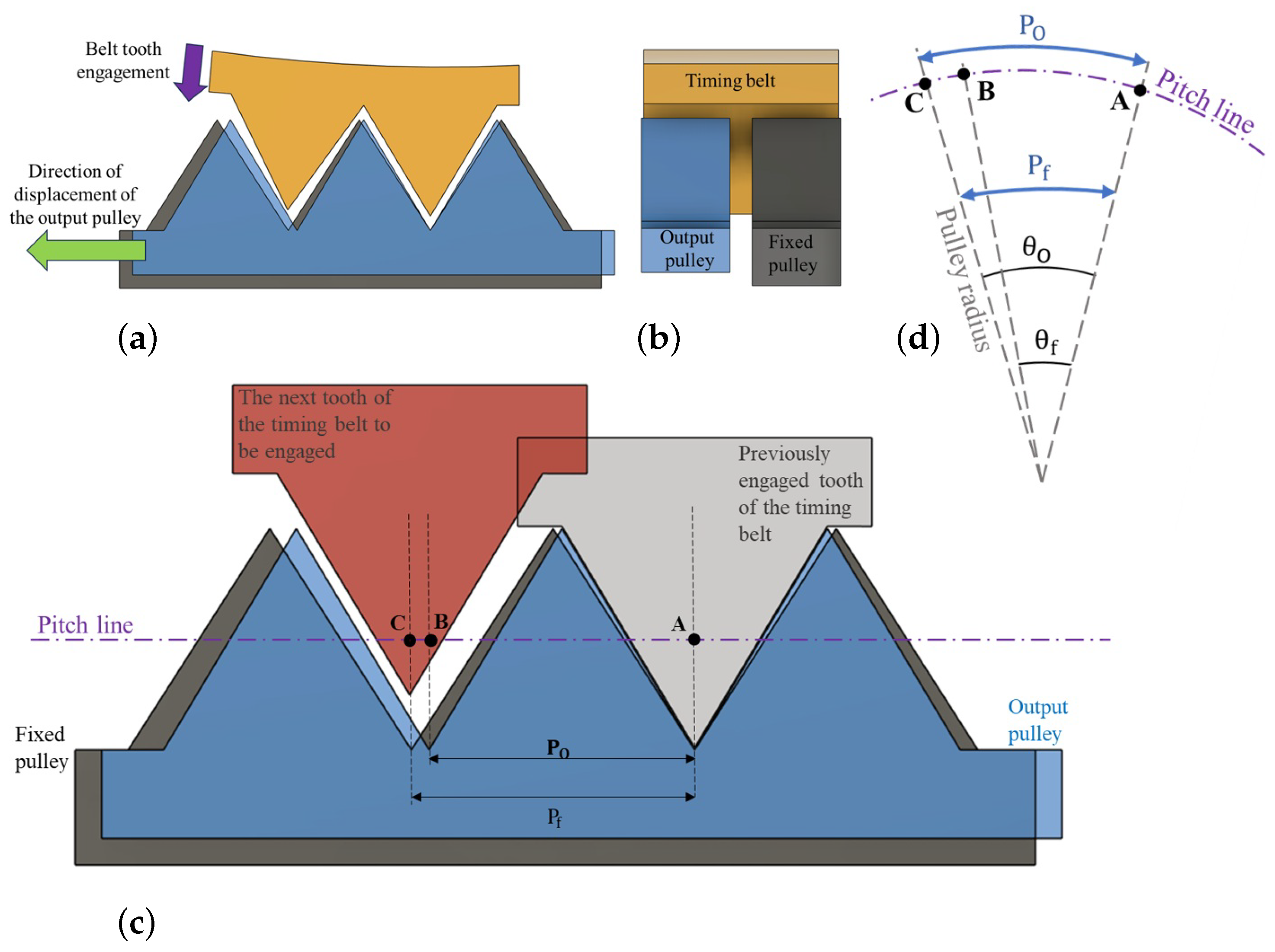
In RM-Act 2.0, the timing belt loops around two central pulleys, one fixed pulley (FP) and one movable output pulley (OP), both coaxial with the rotational axis of the IPs. Similar to a traditional harmonic gearbox (Figure 1c), the stationary and movable pulleys possess nearly identical tooth counts, N f and N o , differing only by a small value t. The timing belt’s active engagement regions are shared between the stationary and movable pulleys.
The FP restricts the belt’s free motion, causing the engagement points to shift as the belt deforms under the influence of the IPs (Figure 1b). This constrained deformation drives the OP, producing the output motion with a single-stage speed reduction, analogous to a conventional harmonic gearbox. This configuration eliminates the need for precision manufacturing of the FS and internal gear, thereby substantially reducing production costs.
In the configuration illustrated in Figure 2a, the belt teeth engage directly with the central pulleys. During engagement, the belt teeth align those of the output pulley (OP) with the fixed pulley (FP). For each belt tooth, the OP advances by a linear distance B C along the common pitch line of the pulleys. This distance is defined as B C = P f P o , resulting in an angular displacement of θ o θ f in the OP. The direction of this angular shift is opposite to the input rotation, where θ f and θ o represent the angular pitches (https://www.engineersedge.com/gears/gear_terminology_and_equations_13806.htm, accessed on: 28 August 2025) of the fixed and output pulleys, respectively.
θ O P = θ o θ f = 360 1 N o 1 N f .
For a complete rotation of the circular plate, the belt teeth sequentially engage with all N f teeth of the fixed pulley, causing the output pulley to rotate by t × 360 N o in the opposite direction. This results in a speed reduction ratio of t N o , analogous to that of a conventional harmonic reducer. Several possible configurations of the belt arrangement can be realized, as illustrated in Figure 3, depending on the value of t, which represents the difference in the number of teeth—and thus the number of contact points between the belt and the central pulleys.

3. RM-Act 2.0—Final Design

This section presents the finalized design of the RM-Act 2.0. The developed model achieves a speed reduction ratio of 9:1 to enable a direct comparison with RM-Act [38]. The components were carefully selected to minimize the actuator’s overall size relative to RM-Act [38], while ensuring the use of commercially available parts and reducing machining requirements to enhance torque density and manufacturability.

3.1. CAD Model

Figure 4 illustrates the CAD model of the single-belt RM-Act 2.0 assembly featuring a pair of idler pulleys. To accommodate the bearings and the tensioning mechanism, dedicated input and output plates were designed. The input plate is a cylindrical structure that precisely houses the motor and includes mounting pockets for the idler pulleys, their bearings, and the tensioning system. The output plate, on the other hand, is a hollow circular component that supports the idler pulleys and tensioning assembly while rotating on bearing D. Snap rings are used to restrict the axial movement of the belt along the pulleys. The fixed pulley is secured to its complementary profile on the top cover of the actuator. The bottom cover supports the motor and driver module responsible for driving the input plate, whereas the top cover supports the output shaft connected to the output pulley, enabling the transmission of the output motion.
Bearings with appropriate specifications were selected to meet the functional requirements while minimizing their width, thereby reducing the actuator’s overall thickness along its axis. Bearings A and B facilitate the free rotation of the output pulley relative to both the motor shaft and the fixed pulley. Bearing C ensures smooth rotation of the idle plates mounted on the input and output plates. Bearings E allow unrestricted rotation of the tensioners, which are mounted on pins within the tensioner support. The belt tensioning system (Figure 5) is specifically designed to minimize slippage of the timing belt and maintain consistent transmission performance.
The tensioner supports are positioned within the tensioner housings, allowing them to slide radially and press the tensioners against the belt. These housings are mounted on the input and output plates. By tightening adjustment screws, the tensioner supports can be moved radially inward to increase the belt tension. The tensioners are designed to maintain uniform tension across the belt segments engaging the output and fixed pulleys.

3.2. Parts and Material Specification

The RM-Act 2.0 uses an Antigravity 5006 KV 450 motor (sourced from: Ziyang Ave., Nanchang, Jiangxi, China) (https://store.tmotor.com/product/mn5006-kv450-motor-antigravity-type.html, accessed on: 28 August 2025) and a Poggi® 120-3MGT-15 timing belt (sourced from: Casa del Cuscinetto S.P.A., Livorno, Italy) (https://www.poggispa.com/prodotti/trasmissioni-dentate/#1543231689721-30d496d5-522c, accessed on: 28 August 2025). The idler pulleys, output pulley, and fixed pulley were machined from Poggi GT® 3MR bars (11-3MR-80-AL, 18-3MR-125-AL, and 20-3MR-125-AL, respectively) (sourced from: Casa del Cuscinetto S.P.A., Livorno, Italy) (https://www.poggispa.com/wp-content/uploads/2020/01/050_Barre-dentate-e-flange-per-pulegge-dentate.pdf, accessed on: 28 August 2025). Snap rings of sizes 9, 16, and 18 (sourced from: RS Components S.r.l., Milan, Italy) were used to secure the belts on the idle, output, and fixed pulleys, maintaining a clearance of C 1 = 8.15 mm between the central and idler pulleys. Bearings A, B, C (and E), and D, shown in Figure 4, were selected as SKF-W-638-4-2Z, SKF-W-628-6-2Z, SKF-W-627-3-2Z, and SKF-W-61705, respectively (sourced from: MISUMI Europa GmbH, Frankfurt am Main, Germany). The components were fastened with Ø3 mm pins and M2/M3 screws, all of which were commercially available.
Additional parts, including the driving plates, tensioners, tensioner supports, and covers, were 3D-printed using ABS plastic with FDM technology. The clearance between the idler pulleys and the actuator cover was set to C 2 = 6.4 mm, while the cover itself had a thickness of z = 3 mm. A 3D-printed link (L = 100 mm, W = 12.5 mm, H = 8 mm) was mounted on the output shaft to hold loads during testing, as explained in Section 5. The quantities of each component and whether they were obtained commercially or manufactured/modified in-house are summarized in Table 1.

3.3. Electronics and Control

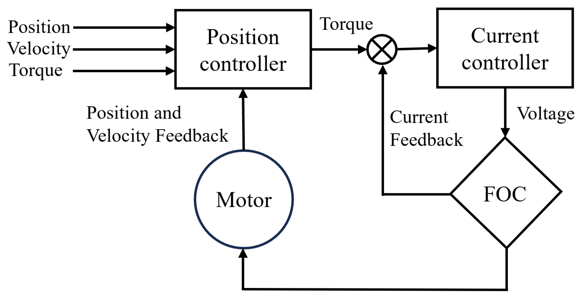
The Moteus r4.8 32-bit microcontroller was used to drive the three-phase brushless motors, equipped with a built-in magnetic encoder for detecting rotor position and current. As depicted in Figure 6, the Moteus controller achieves high steady-state accuracy by employing the field-oriented control (FOC) method for brushless motor management [41]. The FOC controller operates in two stages: an outer stage featuring a proportional-integral-derivative (PID) controller and an inner stage with a proportional-integral (PI) controller. The outer controller generates the desired voltage and provides torque or current for the quadrature-phase (Q phase) [41]. While the outer stage focuses on torque delivery for the Q phase, the inner stage, operating in current mode, fine-tunes the voltage for the Q torque loop. The motor’s control parameters have been detailed in the authors’ earlier work [27].
Building upon this FOC framework, the higher-level position controller (illustrated in Figure 6) accepts position, velocity, and torque inputs as part of a cascaded control structure integrated within the Moteus controller. The commanded position and velocity are used to compute an acceleration term, which is integrated over time to obtain control velocity and position. These control signals are compared against real-time feedback from the encoder to calculate position and velocity errors, which are then processed through a PID-based control law. The resulting torque command combined with any feedforward torque input is passed to the inner FOC loop for actuation.
Although the target position serves as the main input, the inclusion of velocity and torque signals enables smoother trajectory tracking, improved stability, and enhanced torque precision during dynamic operation, ensuring responsive and high-performance control of the RM-Act 2.0 actuator.

4. Testing and Results

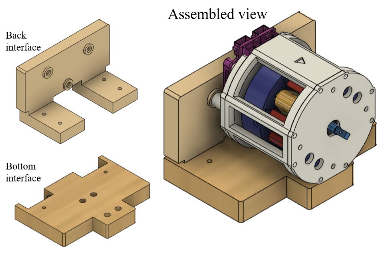
This section details the Python(v3.12.0)-coded tests along with their results. For mounting the RM-Act 2.0 during testing, the bottom and back interfaces (Figure 7) were 3D printed using ABS material.

4.1. Static Tests

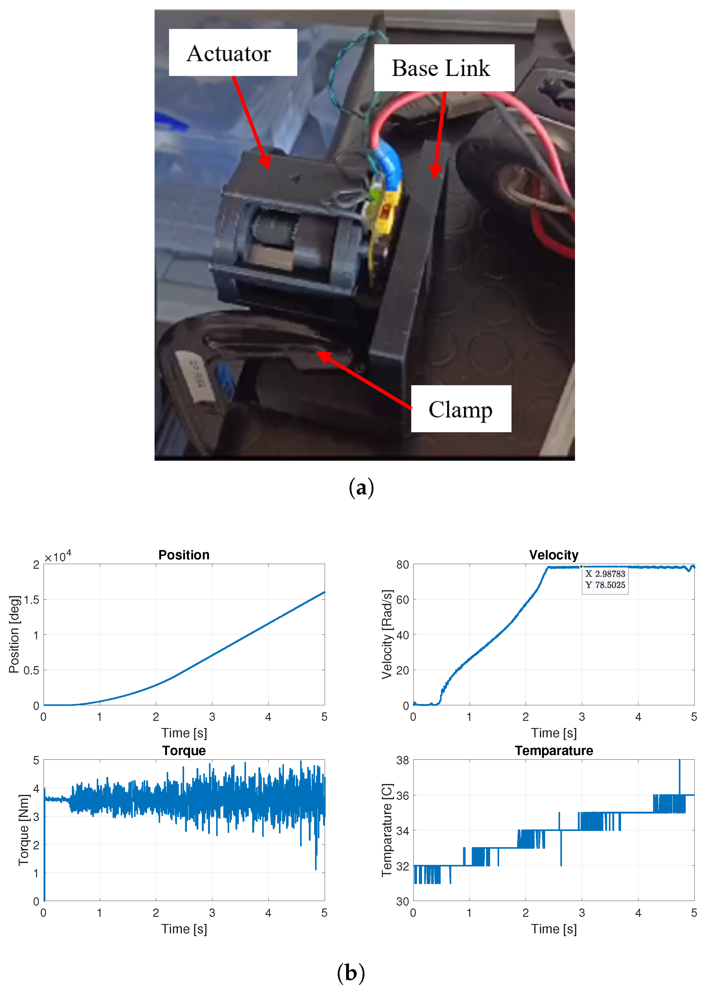
The static tests were conducted to evaluate the torque–deflection characteristics of the RM-Act 2.0. During testing, the actuator was firmly mounted on a laboratory table, aligned horizontally along its rotational axis, using the interfaces and clamps shown in Figure 8a. The output arm was fixed while a controlled input torque was applied. Position, velocity, torque, and current were continuously recorded. A linear torque input, starting from 0.1 Nm, was incrementally applied and held until the position stabilized. Given the 9:1 reduction ratio, the output torque was expected to be nine times the input torque.
The corresponding output position, velocity, torque, and current for an output torque of 5.41 Nm (from an input torque of 0.6 Nm) are shown in Figure 8b.
The stiffness was determined by analyzing the stabilized position and torque values, which led to an identified stiffness of 360.29 Nm/rad. This stiffness corresponds to a backlash of 0.0159° at 0.1 N·m torque. When the input torque exceeded 0.7 Nm, slippage became apparent. Moreover, for static tests conducted with higher input torques, position stabilization could not be reached, as the temperature of the driver circuit exceeded the manufacturer’s specified maximum limit of 60 °C.

4.2. Dynamic Tests

The dynamic tests were conducted to evaluate the actuator’s operational range, focusing on its maximum no-load speed and nominal torque.
For the peak speed test, the actuator was fixed to a platform using C-clamps, maintaining its rotational axis horizontally, as shown in Figure 9a. The output end was left unloaded, and the motor was driven via Python commands to reach its maximum speed with incremental feed-forward torque to overcome friction. Starting from 0.1 Nm, the feed-forward torque was gradually increased. At 0.4 Nm, the actuator reached its peak speed of 78.5 rad/s, as illustrated in Figure 9b, with no further speed increase observed beyond this point.
To determine the nominal torque, the actuator was mounted horizontally on a table. A 3D-printed arm of 0.1 m length was attached to the output, and weights from 0.35 kg to 0.70 kg were applied at the opposite end, as shown in Figure 10a. For each load, the arm was moved from the vertical position to 90°, held for 60 s, and corrected to 100° in code to compensate for deflections and positioning errors. Position, velocity, torque, and temperature were continuously recorded during testing.
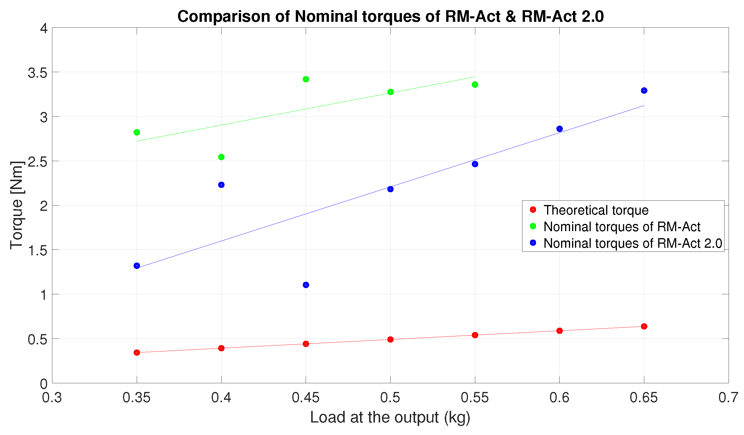
Table 2 summarizes the measured torque values for each load. The theoretical torque, τ theo , was calculated by multiplying the load mass, the acceleration due to gravity, and the arm length. The mean output torque, τ avg , represents the average of the measured torque values over the 60-s holding period. From this, the actuator’s nominal torque was determined to be 3.29 Nm, as shown in Figure 10b.
For loads above 0.65 kg, slippage or overheating (temperature exceeding 65 °C) was observed. The deviation between the theoretical and average measured torque can be attributed to increased internal friction within the actuator, which dissipates part of the motor’s input power. Under no-load conditions, the actuator achieved a full 90° motion. The position compensation implemented during the loaded tests was necessary to account for the elastic deformation of the 3D-printed arm under applied loads.
For additional details, the testing videos are available in the Supplementary Materials.
In this study, we did not conduct cyclic loading tests on the actuator. However, the long-term durability and fatigue behavior of the belt can be inferred from a related study in which an actuator with a compound belt gear train, named EM-Act [27], was developed using a similar type of timing belt. The EM-Act was experimentally tested for over one million loading cycles without showing any signs of belt wear or performance degradation. Since RM-Act 2.0 employs belts that are wider and mechanically stronger, comparable or better fatigue performance can be reasonably expected. Nonetheless, we acknowledge that a dedicated long-term durability test for RM-Act 2.0 would further validate this assumption and will be considered in future work.

5. Model Identification

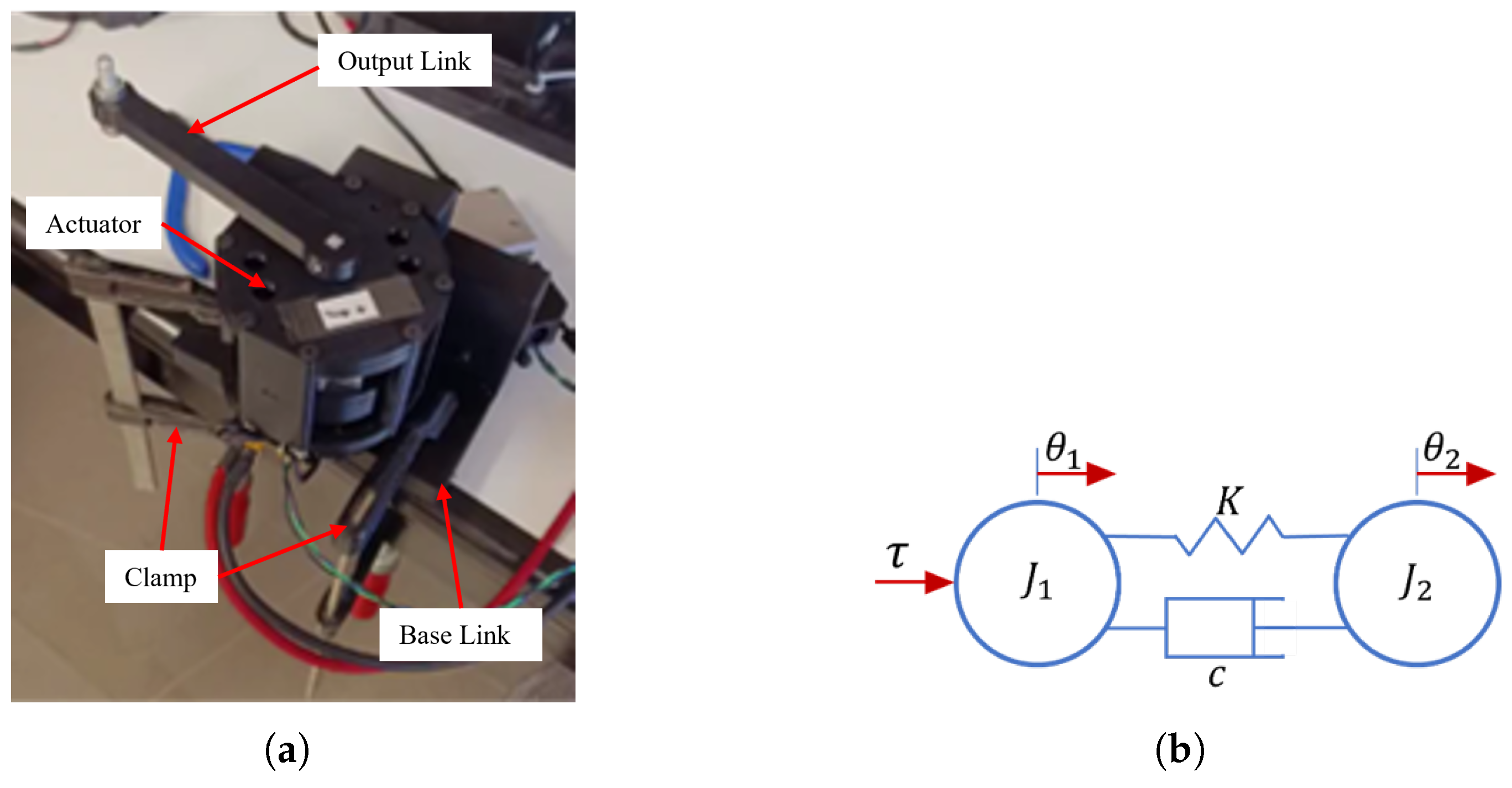
This section presents the dynamic testing performed to evaluate the key parameters of the RM-Act 2.0, namely stiffness, inertia, and friction. For model identification, the actuator was mounted on a laboratory table with its rotational axis oriented vertically, as shown in Figure 11a. A known weight of 10 g was attached to the actuator’s output end, and oscillations were induced by applying a sinusoidal input torque of 0.23 Nm over a frequency range of 0.005 Hz to 100 Hz. The motor position was continuously monitored throughout the test to obtain the Bode plot of the transfer function’s magnitude.
The actuator model was represented by the motor inertia ( J 1 ) and link inertia ( J 2 ), coupled through a torsional spring with stiffness K and a damping element characterized by a damping coefficient c, as illustrated in Figure 11b.
For each applied motor torque, τ , the angular positions of both the motor, θ 1 , and the link, θ 2 , were recorded as system outputs. By defining the angular positions and velocities of the two inertias as the system states, the state-space representation of the actuator dynamics is expressed as follows:
x 1 x 2 x 3 x 4 = 0 0 1 0 0 0 0 1 K J 1 K J 1 c J 1 c J 1 K J 2 K J 2 c J 2 c J 2 x 1 x 2 x 3 x 4 + 0 0 1 J 1 0 τ
The motor’s angular position and velocity are assigned to x 1 and x 3 , while the angular position and velocity of the link are represented by x 2 and x 4 , respectively. Subsequently, a transfer function was employed for the frequency domain analysis. This function is characterized by the presence of one integrator, two complex conjugate poles, and a zero,
θ 1 ( s ) τ ( s ) = g 1 + T 1 s s 1 + s 2 d w n + s 2 1 w n 2
which was generated from the state space form, where
g = 1 J 1 + J 2 ,
2 d w n = c K ,
and
1 w n 2 = J 1 J 2 J 1 K + J 2 K .
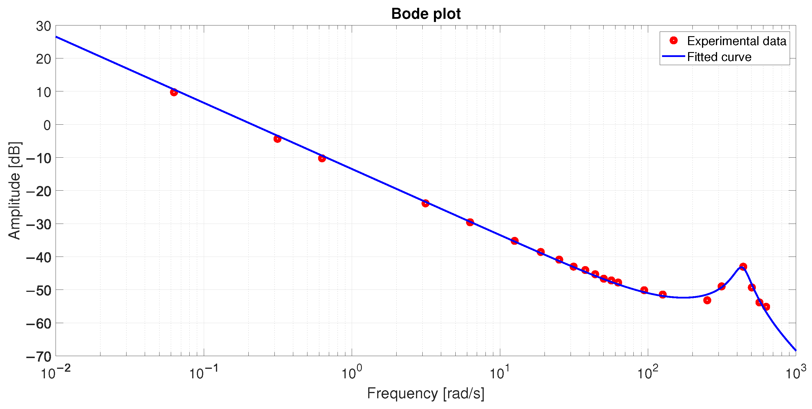
In Figure 12, the Bode plot of the transfer function’s modulus is shown with a fitted curve, which was generated using the MATLAB R2023b curve fitting toolbox (https://www.mathworks.com/products/curvefitting.html, accessed on: 28 August 2025). This curve fitting process helped estimate the parameters g, T 1 , d, and w n . Based on the results from Equations (6)–(8), the values for J 1 , J 2 , K, and c were computed, and the results are presented in Table 3. Notably, the stiffness value obtained from model identification was found to align closely with that derived from the static tests. The final specifications of the RM-Act 2.0 are provided in Table 4. It is important to note that the continuous output power and angular resolution are dependent on the driver’s characteristics, while the nominal voltage is influenced by the motor specifications. Furthermore, the actuator’s nominal speed was calculated using the values of continuous output power and nominal torque. The maximum torque, which was identified in the static tests, was determined under conditions where the end effector was held stationary, with no slippage or overheating of the components occurring.

6. Quick Comparison Between the RM-Act & RM-Act 2.0 Actuators

Although both RM-Act [38] and RM-Act 2.0 operate on the harmonic principle and employ a timing belt in place of a flexspline, they differ substantially in their development objectives, design methodology, and component configuration. While [38] was conceived to introduce a novel concept and achieve the optimal gear ratio within a predefined volume, RM-Act 2.0 emphasizes enhancing torque density at a fixed reduction ratio by effectively utilizing dead volume and mitigating slippage.
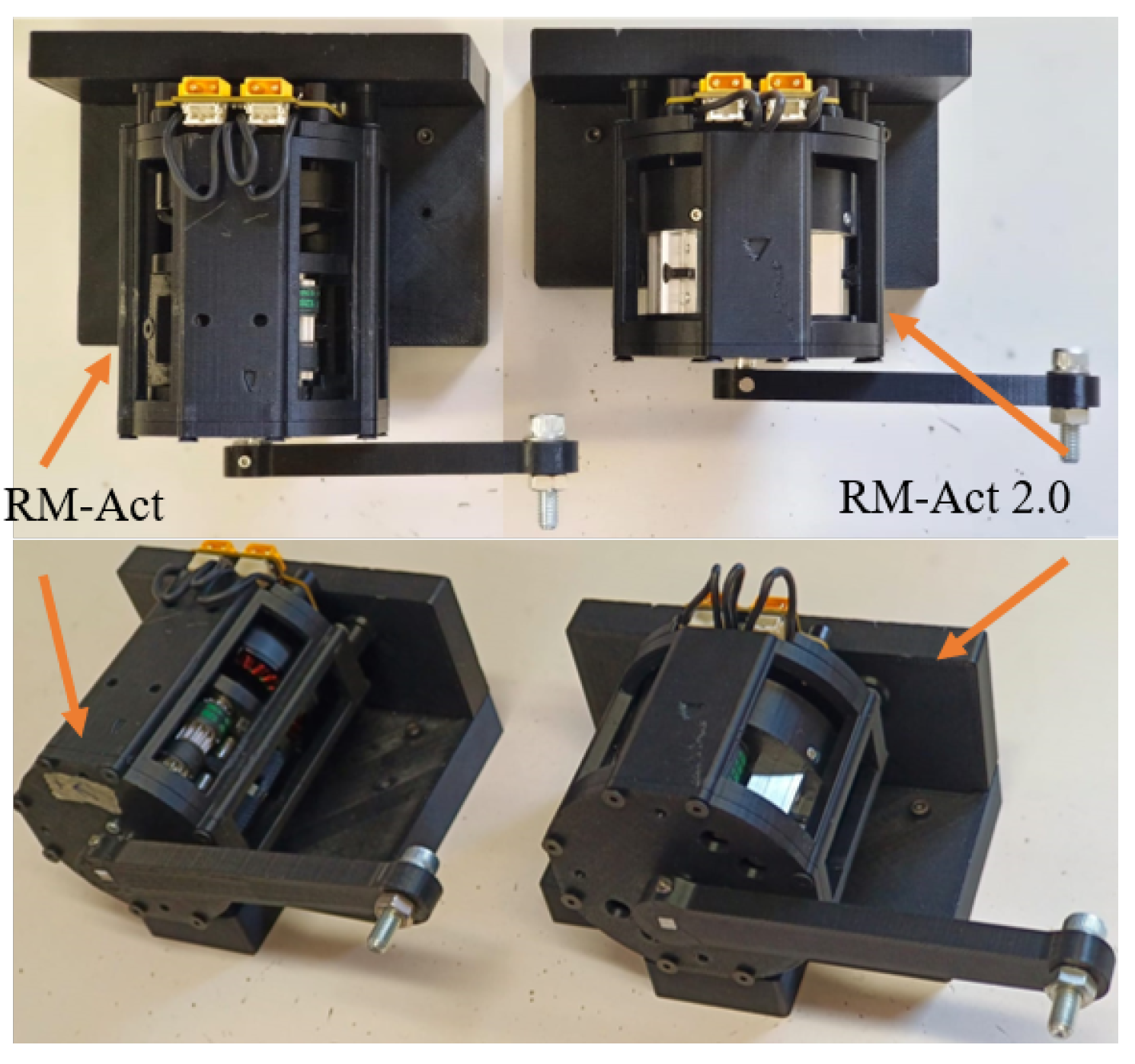
In contrast to [38], the actuator presented here employs a single belt for both central pulleys, which contributes to a reduction in overall actuator length. To further optimize spatial efficiency, the input plate is designed in a cup-shaped form that envelopes the motor surface (Figure 13a). Additionally, the output pulley has been redesigned to accommodate the bearing within its structure, aligning it with the motor shaft. To minimize the use of fasteners and reduce the total number of components, the stop plate used in [38] has been replaced with a complementary geometry integrated into the fixed pulley for secure attachment. The single-belt configuration also reduces the number of snap rings, further decreasing the required assembly space. Thus the total size of the actuator reduces, which can be observed in Figure 14.
This configuration helps minimize slippage, leading to higher peak torque and improved load-bearing capacity in RM-Act 2.0 (Table 4). Experimental observations revealed that once a weight was lifted, the actuator could maintain its position even without power, owing to the increased system stiffness. The torque-dense design of RM-Act 2.0 also reduces power losses, resulting in nominal torque values that closely match the theoretical predictions (Figure 15). Overall, RM-Act 2.0 is approximately 20% smaller and 30% stronger than [38].

7. Conclusions

Harmonic gearboxes, renowned for their exceptional reduction ratios and torque density, continue to represent the state-of-the-art in precision robotics, particularly within collaborative and high-performance applications. This paper presented RM-Act 2.0, a compact and modular harmonic speed reducer designed to achieve a broader range of reduction ratios in a single stage while maximizing torque density. By employing a minimal number of commercially available components, the design effectively minimizes machining requirements and manufacturing costs, thereby enhancing accessibility. Experimental validation confirmed the actuator’s robust performance, exhibiting higher peak torque and reduced volume compared to its predecessor, establishing RM-Act 2.0 as a more compact and powerful actuation solution.
Future work will focus on advancing both the mechanical and control performance of the actuator. Planned directions include idler pulley optimization, friction minimization within the transmission, and dimensional compaction through advanced fabrication techniques such as high-resolution 3D printing for improved strength or injection molding for lightweight shell components. Additionally, the actuator will be integrated into a legged robot’s hip joint to evaluate performance under dynamic locomotion tasks. Further efforts will target the enhancement of frequency response bandwidth, control stability margins, and thermal performance during continuous operation, contributing to a more efficient, reliable, and application-ready actuation system.

Supplementary Materials

The following supporting information can be downloaded at: https://www.mdpi.com/article/10.3390/act14110538/s1, Video S1: RM-Act-2.0-manuscript-supplementary.mp4.

Author Contributions

This research was led by R.K.M.G., who conceptualized the idea, developed the methodology, designed and prototyped the actuator, and performed the experimental validation. He also drafted the initial manuscript. L.M. assisted in designing and setting up the experiments. A.R. contributed to the conceptualization, and participated in writing, reviewing, and editing the manuscript. F.A. and M.G. provided supervision, reviewed the manuscript, and were responsible for project administration and funding acquisition. All authors have read and agreed to the published version of the manuscript.

Funding

This research is partially supported by the European Union’s HORIZON-MSCA-2023-SE-01-01-MSCA Staff Exchanges 2023 Program under the Grant Agreement No 101182891(NEUTRAWEED), and Horizon Research and Innovation Programme under Grant Agreement No. 101070596 (euROBIN), and in part by the Italian Ministry of Education and Research in the framework of the “FoReLab” (Future-oriented Research Lab) Project (Departments of Excellence), and in part by Optimal Control for Computer Aided Manufacturing (OCCAM) Project under Grant FISA 2023-00324 CUP I53C2500070000.

Institutional Review Board Statement

This study did not involve procedures requiring approval from an institutional or regulatory review board.

Informed Consent Statement

Not applicable. This study did not involve humans or animals.

Data Availability Statement

The data presented in this study are available upon request from the author.

Acknowledgments

The authors would like to thank Andrea Di Basco for machining, Salvatore Balestrino for the data and power connections, and Francesco Iotti and Giuseppe Alfonso for support and software advice.

Conflicts of Interest

The authors declare no conflicts of interest.

Abbreviations

The following abbreviations are used in this manuscript:
HGHarmonic Gearboxes
WGWave Generator
FSFlex Spline
CSCircular Spline
HDHarmonic Drive
CADComputer Aided Design
3DThree Dimensional
FDMFused Deposition Modeling
DOFDegree of Freedom

References

  1. Scheinman, V.; McCarthy, J.M.; Song, J.B. Mechanism and actuation. In Springer Handbook of Robotics; Springer International Publishing: Cham, Switzerland, 2016; pp. 67–90. [Google Scholar]
  2. Al Kouzbary, M.; Al Kouzbary, H.; Liu, J.; Khamis, T.; Al-Hashimi, Z.; Shasmin, H.N.; Arifin, N.; Abu Osman, N.A. Robotic Knee Prosthesis with Cycloidal Gear and Four-Bar Mechanism Optimized Using Particle Swarm Algorithm. Actuators 2022, 11, 253. [Google Scholar] [CrossRef]
  3. Yadav, V.; Kumar, D.; Srivastav, A.; Sarangi, S. Modelling and FEM simulation of a rotating hyperelastic spherical balloon actuator. Aust. J. Mech. Eng. 2024, 22, 37–48. [Google Scholar] [CrossRef]
  4. Laffranchi, M.; Tsagarakis, N.; Caldwell, D.G. A compact compliant actuator (CompAct™) with variable physical damping. In Proceedings of the 2011 IEEE International Conference on Robotics and Automation, Shanghai, China, 9–13 May 2011; pp. 4644–4650. [Google Scholar]
  5. Arnaudov, K.; Karaivanov, D.P. Planetary Gear Trains; CRC Press: Boca Raton, FL, USA, 2019. [Google Scholar]
  6. Arm, P.; Zenkl, R.; Barton, P.; Beglinger, L.; Dietsche, A.; Ferrazzini, L.; Hampp, E.; Hinder, J.; Huber, C.; Schaufelberger, D.; et al. Spacebok: A dynamic legged robot for space exploration. In Proceedings of the 2019 International Conference on Robotics and Automation (ICRA), Montreal, QC, Canada, 20–24 May 2019; pp. 6288–6294. [Google Scholar]
  7. Wensing, P.M.; Wang, A.; Seok, S.; Otten, D.; Lang, J.; Kim, S. Proprioceptive actuator design in the mit cheetah: Impact mitigation and high-bandwidth physical interaction for dynamic legged robots. IEEE Trans. Robot. 2017, 33, 509–522. [Google Scholar] [CrossRef]
  8. Bjelonic, M.; Klemm, V.; Lee, J.; Hutter, M. A survey of wheeled-legged robots. In Proceedings of the Climbing and Walking Robots Conference, Ponta Delgada, Portugal, 12–14 September 2022; Springer: Berlin/Heidelberg, Germany, 2022; pp. 83–94. [Google Scholar]
  9. Iotti, F.; Ranjan, A.; Angelini, F.; Garabini, M. OmniQuad: A wheeled-legged hybrid robot with omnidirectional wheels. Mech. Mach. Theory 2025, 214, 106125. [Google Scholar] [CrossRef]
  10. Ranjan, A.; Iotti, F.; Angelini, F.; Garabini, M. TraQuad: A Modular Tracked Legged Multimodal Quadrupedal Robot. IEEE/ASME Trans. Mechatron. 2025, 1–13. [Google Scholar] [CrossRef]
  11. Slatter, R. Weiterentwicklung eines Präzisionsgetriebes für die Robotik; Antriebstechnik: St. Leonard, France, 2000. [Google Scholar]
  12. Sensinger, J.W.; Lipsey, J.H. Cycloid vs. harmonic drives for use in high ratio, single stage robotic transmissions. In Proceedings of the 2012 IEEE International Conference on Robotics and Automation, Saint Paul, MN, USA, 14–18 May 2012; pp. 4130–4135. [Google Scholar]
  13. Schorsch, J. Compound Planetary Friction Drive. Patent No. 2013496, 20 September 2016. [Google Scholar]
  14. Schreiber, H.; Schmidt, M. Getriebe. Patent No. DE 10 2015105 525 A1, 10 April 2015. [Google Scholar]
  15. Kanai, Y.; Fujimoto, Y. Torque-sensorless control for a powered exoskeleton using highly back-drivable actuators. In Proceedings of the IECON 2018-44th Annual Conference of the IEEE Industrial Electronics Society, Washington, DC, USA, 21–23 October 2018; pp. 5116–5121. [Google Scholar]
  16. Fankhauser, P.; Hutter, M. Anymal: A unique quadruped robot conquering harsh environments. Res. Featur. 2018, 126, 54–57. [Google Scholar]
  17. Kang, I.; Peterson, R.R.; Herrin, K.R.; Mazumdar, A.; Young, A.J. Design and Validation of a Torque-Controllable Series Elastic Actuator-Based Hip Exoskeleton for Dynamic Locomotion. J. Mech. Robot. 2022, 15, 021007. [Google Scholar] [CrossRef]
  18. Font-Llagunes, J.M.; Lugrís, U.; Clos, D.; Alonso, F.J.; Cuadrado, J. Design, Control, and Pilot Study of a Lightweight and Modular Robotic Exoskeleton for Walking Assistance After Spinal Cord Injury. J. Mech. Robot. 2020, 12, 031008. [Google Scholar] [CrossRef]
  19. Sun, Z.; Li, Y.; Zi, B.; Chen, B. Development and dynamic state estimation for robotic knee–ankle orthosis with shape memory alloy actuators. J. Mech. Des. 2024, 146, 013302. [Google Scholar] [CrossRef]
  20. Li, R.; Zhou, G.; Huang, J.; Li, J. Lightweight design and verification of space harmonic drive. Int. J. Mech. Sci. 2025, 296, 110302. [Google Scholar] [CrossRef]
  21. Kondo, K.; Takada, J. Study on tooth profiles of the harmonic drive. J. Mech. Des. 1990, 112, 131–137. [Google Scholar] [CrossRef]
  22. Maiti, R. A novel harmonic drive with pure involute tooth gear pair. J. Mech. Des. 2004, 126, 178–182. [Google Scholar] [CrossRef]
  23. Yao, Y.; Lu, L.; Chen, X.; Xie, Y.; Yang, Y.; Xing, J. A Novel Cycloid Tooth Profile for Harmonic Drive with Fully Conjugate Features. Actuators 2025, 14, 187. [Google Scholar] [CrossRef]
  24. Chang, J.; Chang, I. Design of high ratio gear reducer using vernier differential theory. J. Mech. Des. 2021, 143, 023401. [Google Scholar] [CrossRef]
  25. Megalingam, R.K.; Vadivel, S.R.R.; Manoharan, S.K.; Pula, B.T.; Sathi, S.R.; Gupta, U.S.C. Reduced Kinematic Error for Position Accuracy in a High-Torque, Lightweight Actuator. Actuators 2024, 13, 218. [Google Scholar] [CrossRef]
  26. Ling, Z.; Zhao, L.; Xiao, D.; Zhou, Y.; Ma, C.; He, K.; Liu, G. A Novel Strain Wave Gear Reducer with Double Flexsplines. Actuators 2023, 12, 313. [Google Scholar] [CrossRef]
  27. Muttathil Gopanunni, R.K.; Martignetti, L.; Iotti, F.; Ranjan, A.; Angelini, F.; Garabini, M. EM-Act: A Modular Series Elastic Actuator for Dynamic Robots. IEEE Open J. Ind. Electron. Soc. 2024, 5, 468–480. [Google Scholar] [CrossRef]
  28. Galea, M.; Hamiti, T.; Gerada, C. Torque density improvements for high performance machines. In Proceedings of the 2013 International Electric Machines & Drives Conference, Chicago, IL, USA, 12–15 May 2013; pp. 1066–1073. [Google Scholar]
  29. Lin, X.; Wu, Y.; Olson, G.F.; Liu, J.; Wu, L.; Peretti, L. Optimal Pole-Transition Current Distribution for Constant Torque Maintenance and Stator Copper Loss Minimization in Variable-Pole Machines. IEEE Trans. Transp. Electrif. 2025, 11, 10573–10582. [Google Scholar] [CrossRef]
  30. Lin, X.; Liu, J.; Liu, Z.; Gao, Y.; Peretti, L.; Wu, L. Model-Free Current Predictive Control for PMSMs With Ultra-Local Model Employing Fixed-Time Observer and Extremum-Seeking Method. IEEE Trans. Power Electron. 2025, 40, 10682–10693. [Google Scholar] [CrossRef]
  31. Xu, R.; Shen, X.; Lin, X.; Liu, Z.; Xu, D.; Liu, J. Robust Model Predictive Control of Position Sensorless Driven IPMSM Based on Cascaded EKF-LESO. IEEE Trans. Transp. Electrif. 2025, 11, 8824–8832. [Google Scholar] [CrossRef]
  32. Uppalapati, K.K.; Calvin, M.D.; Wright, J.D.; Pitchard, J.; Williams, W.B.; Bird, J.Z. A magnetic gearbox with an active region torque density of 239 N· m/L. IEEE Trans. Ind. Appl. 2017, 54, 1331–1338. [Google Scholar] [CrossRef]
  33. Shin, W.; Ahn, B.; Kwon, S. A low backlash and highly efficient gearbox for robot actuator. In Proceedings of the 2024 IEEE International Conference on Advanced Intelligent Mechatronics (AIM), Boston, MA, USA, 15–19 July 2024; pp. 224–229. [Google Scholar]
  34. Zhou, G.; Yang, Y.; Xie, R.; Chang, L.; Gao, B. A novel harmonic movable tooth drive with almost surface contact conjugate tooth profiles: Parametric design, modification and analysis. Proc. Inst. Mech. Eng. Part C J. Mech. Eng. Sci. 2024, 238, 9032–9048. [Google Scholar] [CrossRef]
  35. Buleandra, D.; Băneasă, A.; Donca, R. 3D Printed Harmonic Drive for Legged Mobile Robots. In Proceedings of the International Conference on Robotics in Alpe-Adria Danube Region, Cluj-Napoca, Romania, 5–7 June 2024; Springer: Berlin/Heidelberg, Germany, 2024; pp. 597–605. [Google Scholar]
  36. Pacana, J.; Pacana, A.; Oliwa, R. Possibilities of Using Selected Additive Methods for the Production of Polymer Harmonic Drive Prototypes. Materials 2023, 16, 4073. [Google Scholar] [CrossRef] [PubMed]
  37. Dini, M. Harmonic Drive with Compact Structure Made by Plastic Material. Patent No. US20250012348A1, 9 January 2025. [Google Scholar]
  38. Muttathil Gopanunni, R.K.; Martignetti, L.; Angelini, F.; Garabini, M. RM-Act: A Novel Modular Harmonic Actuator. Actuators 2025, 14, 492. [Google Scholar] [CrossRef]
  39. Pettersson, M.; Ölvander, J. Drive train optimization for industrial robots. IEEE Trans. Robot. 2009, 25, 1419–1424. [Google Scholar] [CrossRef]
  40. Scaldaferri, A.; Tolomei, S.; Iotti, F.; Gambino, P.; Pierallini, M.; Angelini, F.; Garabini, M. Otto-Design and Control of an 8-DoF SEA-driven Quadrupedal Robot. IEEE Open J. Ind. Electron. Soc. 2025, 6, 820–839. [Google Scholar] [CrossRef]
  41. Yunfei, L.; Chengning, Z. A comparative experimental analysis of PMSM between deadbeat prediction current control and field-oriented control. Energy Procedia 2019, 158, 2488–2493. [Google Scholar] [CrossRef]
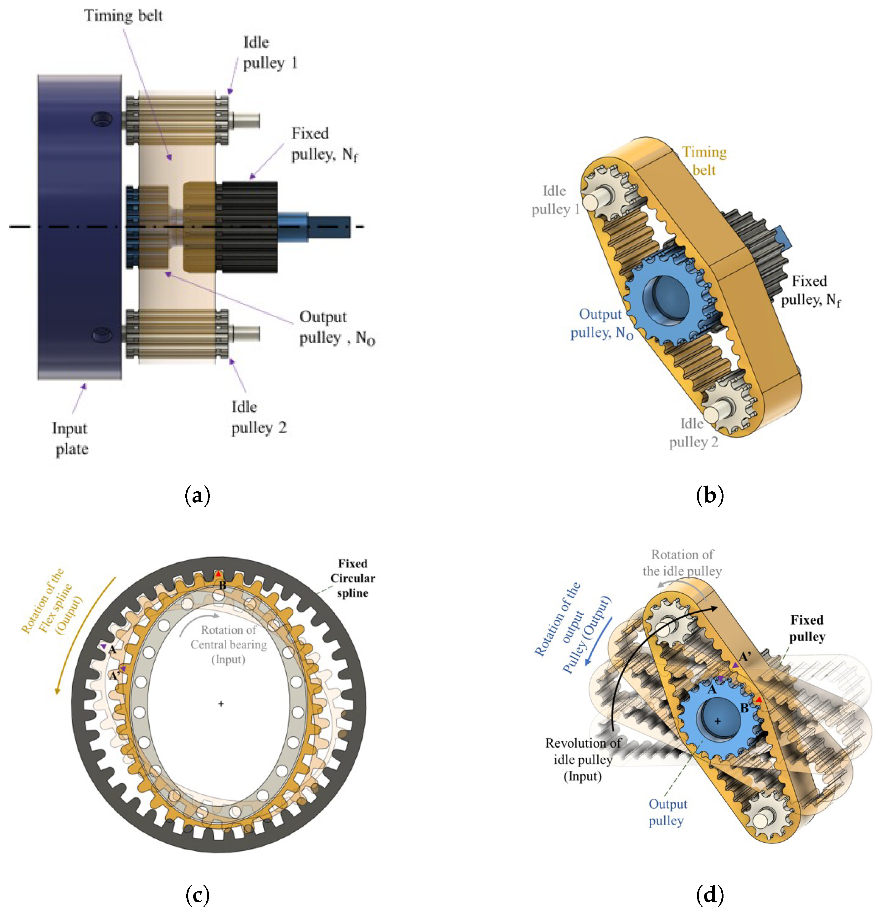
Figure 1. Design concept and engagement mechanism of the belt tooth with the central pulleys (actuation principle is adapted from ref. [38]). Here, (a) illustrates the side view of the key components in the RM-Act 2.0; (b) presents the timing belt and idler pulley arrangement in isometric view; (c) depicts the tooth engagement concept and flex spline motion in a standard harmonic drive; and (d) shows the operating principle of the timing belt mechanism in RM-Act 2.0.
Actuators 14 00538 g001
Figure 2. Working principle of tooth engagement process (adapted from ref. [38]). (a) Design concept foot belt-pulley tooth engagement; (b) Motion imparted on the output pulley by the engaging belt; (c) Engagement of the belt tooth with the central pulleys; (d) Diametrical and angular pitch of the pulleys.
Actuators 14 00538 g002
Figure 3. Possible arrangements of idle and central pulleys for different t values: (a) t = 1 , (b) t = 2 , 4 , 6 , , (c) t = 3 , 6 , 9 , .
Actuators 14 00538 g003
Figure 4. Isometric view of the RM-Act 2.0 assembly (Top-left); Sectional view (Top-right); Exploded view (Bottom).
Actuators 14 00538 g004
Figure 5. Belt tensioning system of the RM-Act 2.0. Four tensioners are placed to tighten the belt with help of tensioning screws.
Actuators 14 00538 g005
Figure 6. Control scheme of the Moteus controller with a two-stage cascade [27].
Actuators 14 00538 g006
Figure 7. Assembly of RM-Act 2.0 on a mount to prepare a setup for experimental validation. Interfaces to mount the RM-Act 2.0 for tests (left), Assembled view (right).
Actuators 14 00538 g007
Figure 8. Experimental validation of the actuator with static tests (test procedure is adapted from ref. [38]). (a) Experimental setup for static tests; (b) Results of static tests at the output.
Actuators 14 00538 g008
Figure 9. (a) Experimental setup for Maximum speed; (b) Results of Maximum speed tests at the output. The test procedure is adapted from ref. [38].
Actuators 14 00538 g009
Figure 10. (a) Experimental setup for Nominal torque; (b) Results of Nominal torque tests at the output. The test procedure is adapted from ref. [38].
Actuators 14 00538 g010
Figure 11. (a) Experimental setup for model identification tests; (b) Actuator stiffness model. The identification procedure is adapted from ref. [38].
Actuators 14 00538 g011
Figure 12. Curve fitting of Bode plot. The calculation procedure is adapted from ref. [38].
Actuators 14 00538 g012
Figure 13. Modifications for reduced volume. Input plate and Top cover of the actuator were modified.
Actuators 14 00538 g013
Figure 14. Comparison of the size of RM-Act and RM-Act 2.0.
Actuators 14 00538 g014
Figure 15. Comparison of the Nominal torques of RM-Act and RM-Act 2.0. w.r.t the Theoretical torque.
Actuators 14 00538 g015
Table 1. List of Components Used in RM-Act 2.0 Assembly.
ComponentSpecification/ModelQty.Source/ManufacturingType
MotorAntigravity 5006 KV 4501T-Motor, Jiangxi, ChinaCommercial
Timing beltPoggi® 120-3MGT-151Casa del Cuscinetto S.P.A., Livorno, ITCommercial
Idler pulleyPoggi GT® 11-3MR-80-AL2Casa del Cuscinetto S.P.A., Livorno, ITCommercial + In-house machining
Output pulleyPoggi GT® 18-3MR-125-AL1Casa del Cuscinetto S.P.A., Livorno, ITCommercial + In-house machining
Fixed pulleyPoggi GT® 20-3MR-125-AL1Casa del Cuscinetto S.P.A., Livorno, ITCommercial + In-house machining
Snap ringsSizes 9, 16, and 184,1,1RS Components S.r.l., Milan, ITCommercial
Bearing ASKF W-638-4-2Z1MISUMI, Frankfurt am Main, DECommercial
Bearing BSKF W-628-6-2Z1MISUMI, Frankfurt am Main, DECommercial
Bearing C (and E)SKF W-627-3-2Z16MISUMI, Frankfurt am Main, DECommercial
Bearing DSKF W-617051MISUMI, Frankfurt am Main, DECommercial
FastenersØ3 mm pins, M2/M3 screwsVariousCasa del Cuscinetto S.P.A., Livorno, ITCommercial
tensionersN/A1 setsAluminumIn-house
supports, coversN/A1 each3D printed using ABS (FDM)In-house
Moteous microcontrollerr4.8 32-bit1Mjbots, Cambridge, MA, USACommercial
Table 2. Actuator holding torque test. Loads were placed on an arm connected to the rotation shaft of the actuator. The load were lifted from the vertical axis to the horizontal axis and held for 60 s in the horizontal position. The theoretical torque τ theo and mean average torques τ avg are presented.
Sl. NoLoad (kg) τ theo τ avg
10.3500.34331.3202
20.4000.39242.2310
30.4500.44141.1047
40.5000.49052.1817
50.5500.53952.4637
60.6000.58862.8606
70.6500.63763.2913
80.7000.6867
Table 3. Experiment results of the parameter identification tests.
ParameterSymbolValue
Motor inertia J 1 2.1 × 10⁻³ kg·m2
Link inertia J 2 1.2 × 10⁻² kg·m2
Total stiffnessK360.29 Nm/rad
Frictionc3.4 × 10−1 Nm·s2/rad
Table 4. Specifications of RM-Act 2.0 in comparison with RM-Act.
ParameterUnitRM-ActRM-Act 2.0Relative Change (%)
Size (Diameter × Length)mm 70 × 95 75 × 75 −21.05 (Length)
Weightkg0.3330.329−1.2
Reduction ratio9:19:10.0
Number of stages110.0
Total stiffnessNm/rad130.4360.3+176.4
Continuous output powerW4504500.0
Max. nominal torque (Load)Nm (kg)3.36 (0.55)3.29 (0.65)−2.1
Max. peak torqueNm3.965.41+36.6
Max. speedrad/s86.078.5−8.7
Active rotation angleContinuousContinuous0.0
Angular resolutionDeg360/16,384360/16,3840.0
Nominal voltageV24240.0
Disclaimer/Publisher’s Note: The statements, opinions and data contained in all publications are solely those of the individual author(s) and contributor(s) and not of MDPI and/or the editor(s). MDPI and/or the editor(s) disclaim responsibility for any injury to people or property resulting from any ideas, methods, instructions or products referred to in the content.