Article

Design and Analysis of a High-Speed Slotless Permanent Magnet Synchronous Motor Considering Air-Gap Airflow

1
Guangdong Key Laboratory of Electromagnetic Control and Intelligent Robots, Shenzhen University, Shenzhen 516808, China
2
National Key Laboratory of Green and Long-Life Road Engineering in Extreme Environment (Shenzhen), Shenzhen University, Shenzhen 516808, China
*
Author to whom correspondence should be addressed.
Actuators 2025, 14(11), 530; https://doi.org/10.3390/act14110530 (registering DOI)
Submission received: 8 September 2025 / Revised: 24 October 2025 / Accepted: 27 October 2025 / Published: 31 October 2025

Abstract

The air-gap airflow significantly influences the performance of high-speed slotless permanent magnet synchronous motors (HSSPMSM), yet this critical factor is frequently overlooked during the design phase, resulting in performance deviations. This paper presents the design and multi-physical analysis of a 10 kW/40,000 rpm HSSPMSM, explicitly accounting for air-gap airflow effects. A comprehensive coupling model integrating electromagnetic, thermal, mechanical, and airflow fields is established to guide the motor design. Based on this analysis, the motor dimensions and parameters are determined, and a prototype is fabricated. Experimental validation demonstrates that the developed HSSPMSM successfully meets the design specifications. Considering air-gap airflow can obtain more accurate thermal design results with an accuracy improvement of 6.8% compared to not considering air-gap airflow. The close agreement between the simulated and measured performance confirms the effectiveness of the proposed design methodology that incorporates airflow effects.

1. Introduction

HIGH-SPEED permanent magnet synchronous motors (HSPMSMs) have gained popularity due to their exceptional performance characteristics, such as high power density, compact size, and efficiency. As a result, HSPMSMs have been applied in various industrial applications like gas compressors, turbines, and flywheel energy storage [1,2,3]. HSPMSMs are also widely used in the aerospace field, such as in electrical environmental control systems, electro-hydraulic actuators, and high-speed starting and generating systems [4,5,6]. However, the design of HSPMSMs is a challenging task. When the motor rotates at high speeds, the rotor is subjected to intense stress. The magnetic field frequency of the motor is directly proportional to its rotational speed, which leads to a large eddy current loss in HSPMSMs. The electromagnetic field, mechanical field, and thermal field of the HSPMSMs exhibit strong coupling [7]. Therefore, the analysis and design of high-speed motors require consideration of multiphysics field coupling.
In recent years, scholars have undertaken research on the multiphysics design and analysis of HSPMSM. In [8], an electromagnetic–mechanical finite element model of a PMSM is proposed. In [9], a high-precision 10-pole 12-slot (Q12p5) permanent magnet synchronous motor (PMSM) is constructed through the coupling and analytical modeling of the magnetic, electric, thermal, and vibro-acoustic domains. In [10], a multiphysics modeling dedicated to the interior permanent magnet synchronous motor (IPMSM) for high speeds is proposed, covering magnetic, electric, thermal, and mechanical aspects. The analysis of the electro-mechanical characteristics of a PMSM is presented in [11]. In [12], a multiphysics analytical model of a double-salient V-shaped IPM with concentrated windings was proposed. Taking into account the mutual influences among the multiphysics performances during the optimization process, an optimized HP-UHSM is developed in [13]. In [14], a high torque density PMSM is developed based on an analysis in terms of electromagnetic and thermal. Considering electromagnetic, thermal, and mechanical strength, a multi-objective optimal design of the PMSM is presented in [15]. In [16], a multi-objective and multiphysics design optimization method for a 12/10 switched reluctance motor (SRM) considering both thermal and electromagnetic performances simultaneously was proposed. In [17], an axial PMSM is designed, considering electric, thermal, and mechanical performance. In [18], an HSPMSM is designed and analyzed considering the electromagnetic, thermal, and mechanical performance. The slotless PMSM has the advantages of minimal torque ripple and high efficiency, making it suitable for high-speed operation [19]. In [20], a high-speed slotless PMSM (HSSPMSM) is designed and analyzed in terms of electromagnetic, mechanical strength, rotor dynamics, and thermal.
The rapid rotation of the rotor induces airflow movement, which will alter the heat dissipation conditions of the HSPMSM. Neglecting the impact of airflow movement will lead to an irrational cooling design, increasing the size of the cooling components. Thus, the HSPMSM design should consider the influence of the air-gap airflow.
In this paper, the design and analysis of HSPMSM considering the influence of air-gap airflow are conducted. The HSPMSM adopts a slotless structure to achieve high efficiency and low torque ripple. By analyzing the coupling relationships among electromagnetic, airflow, thermal, and mechanical fields, reasonable HSSPMSM dimensional parameters can be determined.
The remainder of this paper is organized as follows. In Section 2, the structure of the HSSPMSM is presented. The dimensional parameters of the motor are determined through the analysis of the electromagnetic field, flow field, temperature field, and mechanical field. In Section 4, a HSPMSM is developed, and the experiment verification is presented. Finally, the conclusions are drawn in Section 5.

2. Multi-Physical Field in HSSPMSM

The structure of the HSSPMSM proposed is presented in Figure 1. This motor features an inner rotor structure with an overall concentric nested layout. Its core component includes the stator core, three-phase winding, rotor Halbach array, and carbon fiber sleeve. The rotor assembly is rigidly connected around a shaft, on the outer side of which a Halbach array is fixedly mounted. A carbon fiber sleeve fits tightly over the outer side of the Halbach array, forming an interference fit with it. This sleeve provides radial constraint for the permanent magnets.
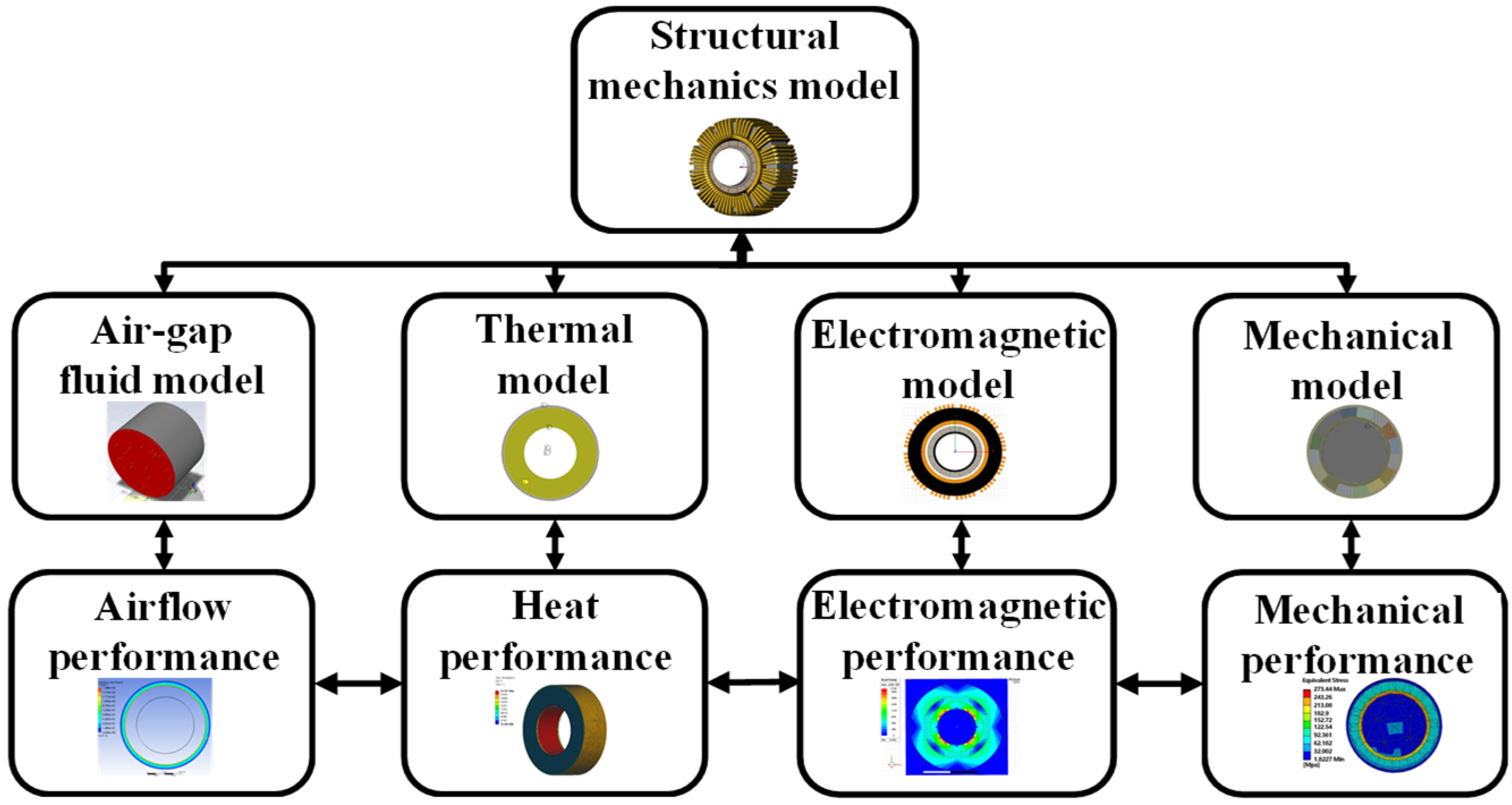
The HSSPMSM exhibits complex multi-physical field interactions with their coupling relationships illustrated in Figure 2. The electromagnetic field, influenced by stator current and motor structure, generates both driving torque and core losses, which, together with copper losses, constitute the heat sources in the thermal field. An iterative bidirectional coupling exists between the electromagnetic field and the thermal field, wherein temperature variations update material properties while recalculated losses conversely act upon the thermal field until thermal equilibrium is achieved. Simultaneously, the electromagnetic field and structural field form a bidirectional coupling through the exchange of electromagnetic torque and mechanical stress data to reach dynamic equilibrium, with the effect of temperature on material elastic modulus incorporated into rotor stress and strain calculations. The rotor speed determined by the structural field unidirectionally drives the airflow field, which computes the convective heat transfer coefficient that subsequently functions as a boundary condition acting unidirectionally on the thermal field to facilitate accurate temperature prediction. Therefore, it is necessary to adopt a comprehensive multiphysics analysis approach in HSSPMSM design.

3. Multi-Physical Design and Analysis of the HSSPMSM Considering Air-Gap Airflow

3.1. Motor Design Process

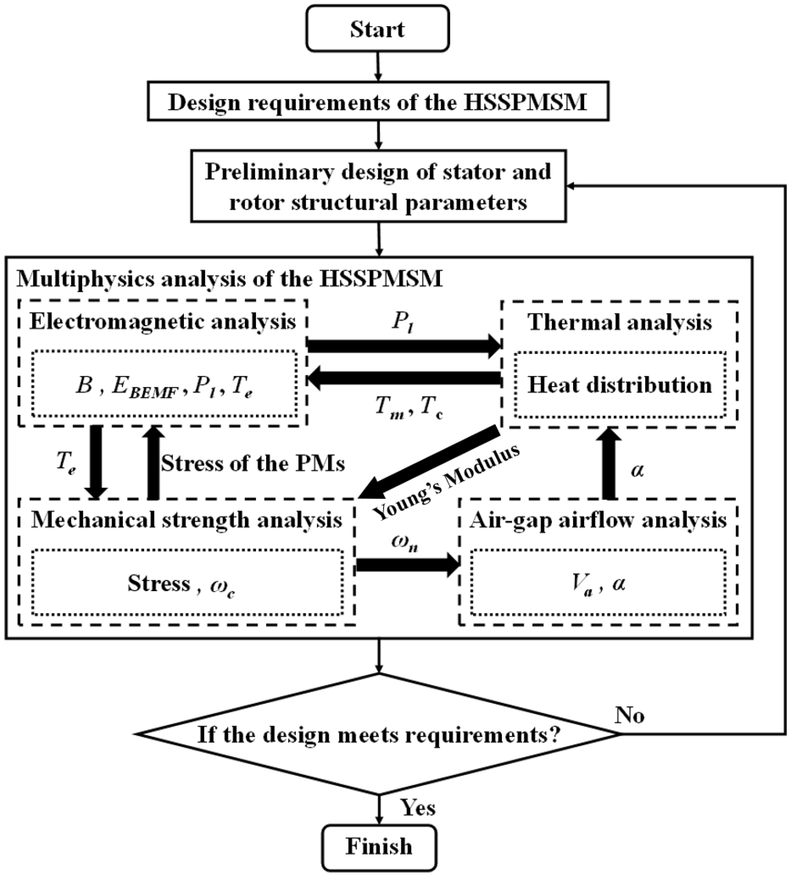
In this paper, a HSSPMSM is designed. The design requirements of the HSSPMSM are listed in Table 1. Firstly, the magnetic field analysis method is used to obtain the initial dimensions that meet the requirements of the magnetic field, back electromotive force, and power. Based on the initial dimensions, multiphysics field design is carried out to comprehensively meet the electromagnetic, thermal, and mechanical performance requirements. Figure 3 shows the multiphysics field design process of this paper, which ensured the final design met all performance targets. Key parameters derived from the electromagnetic analysis include the magnetic flux density B, the back electromotive force EBEMF (back-EMF), and the total losses Pl (comprising core and copper losses), as well as the output torque Te. The mechanical strength analysis informs the first-order critical speed ωc and the rotational speed ωn, both crucial for ensuring structural integrity. The air-gap airflow analysis provides the air-gap airflow Va and the heat dissipation coefficient α, essential for thermal management. Additionally, the thermal analysis yields the temperatures of the magnet Tm and copper Tc, vital for maintaining the operational efficiency of the HSSPMSM and preventing overheating.

3.2. Initial Dimensions Determination

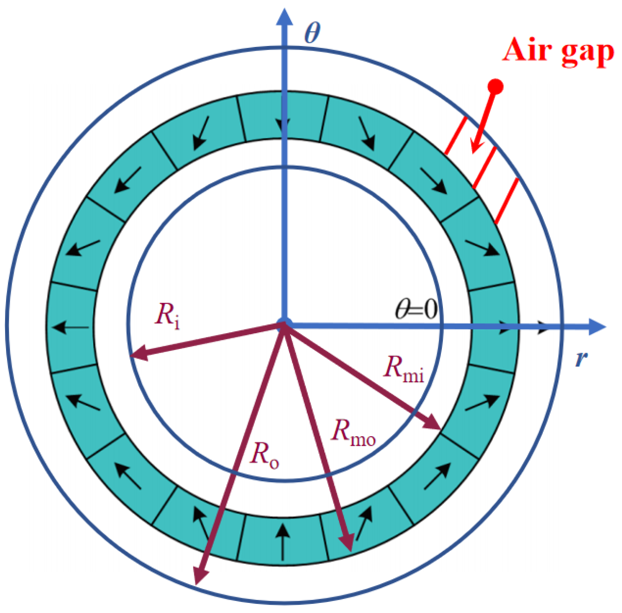
To obtain initial determination parameters, the analytical magnetic field model of the HSSPMSM is built. The polar coordinate diagram of the motor is presented in Figure 4. According to Figure 4, the Laplace equation of the magnetic field of the air gap and magnet can be deduced as (1) and (2).
2 φ r 2 + 1 r φ r + 1 r 2 2 φ θ 2 = 0
2 φ 1 r 2 + 1 r φ 1 r + 1 r 2 2 φ 1 θ 2 = 1 μ r · M
where φ denotes the scalar magnetic potential in the air-gap domain, M is the magnitude of remanent magnetization.
The magnetization of the Halbach array can be derived as (3) and (4) [21].
M r = M c o s θ θ m , t , 0 θ < π α pr 2 p l , i = 1 M c o s θ θ m , t , π 2 i 1 α pr 2 p l θ < π 2 i 1 + α pr 2 p l , i = 2,3 , 2 l M c o s θ θ m , t , π 2 × 2 l α pr 2 p l θ < π 2 × 2 l 2 p l , i = 2 l + 1 0 , π 2 i 1 + α pr 2 p l θ < π 2 i α pr 2 p l , i = 1,2 , 2 l
M θ = M s i n θ θ m , t , 0 θ < π α pr 2 p l , i = 1 M s i n θ θ m , t , π 2 i 1 α pr 2 p l θ < π 2 i 1 + α pr 2 p l , i = 2,3 , 2 l M s i n θ θ m , t , π 2 × 2 l α pr 2 p l θ < π 2 × 2 l 2 p l , i = 2 l + 1 0 , π 2 i 1 + α pr 2 p l θ < π 2 i α pr 2 p l , i = 1,2 , 2 l
where Mr is the radial component of the remanent magnetization, and Mθ is the tangential component of the remanent magnetization.
Combining (1)–(4), the magnetic field model can be deduced as (5) and (6).
B r = n b 1 n r R o 2 n 1 R m o R o 2 n + 1 + R m o r 2 n + 1   c o s 2 n θ
B θ = n b 1 n r R o 2 n 1 R m o R o 2 n + 1 R m o r 2 n + 1   s i n 2 n θ
where Br is the radial component of the magnetic field, and Bθ is the tangential component of the magnetic field.
The magnetic field model includes the main radius dimensions of the HSSPMSM. By adjusting the radius dimensions, it can meet the design requirements of the magnetic field and the induced electromotive force. The initial dimensions and magnetization parameter of the HSSPMSM are listed in Table 2.

3.3. Electromagnetic Analysis of the HSSPMSM

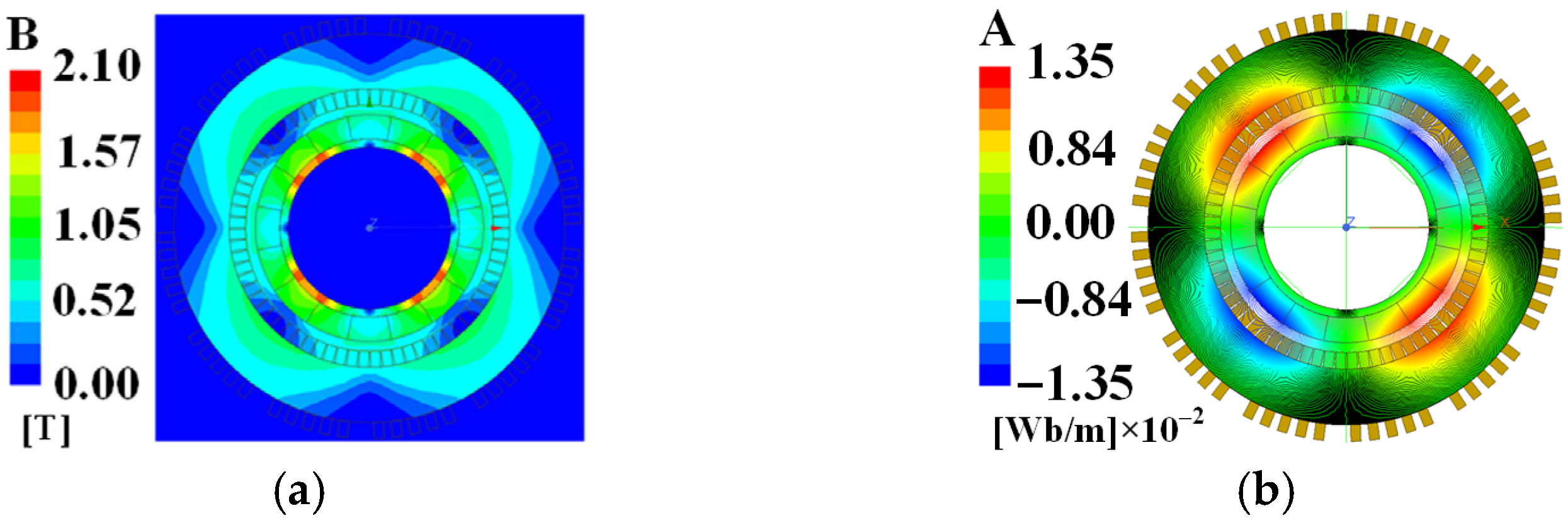
The electromagnetic analysis is conducted by the finite element method (FEM), and the performance characteristics of the HSSPMSM under no-load conditions are obtained. Figure 5 shows the magnetic flux density and magnetic vector potential distribution of the HSSPMSM. The maximum flux density of the HSSPMSM is about 2.10 T at the electrical pure iron of steel 1008. The magnetic field of the Halbach array shows two pairs of poles due to its strong magnetism and self-shielding properties.
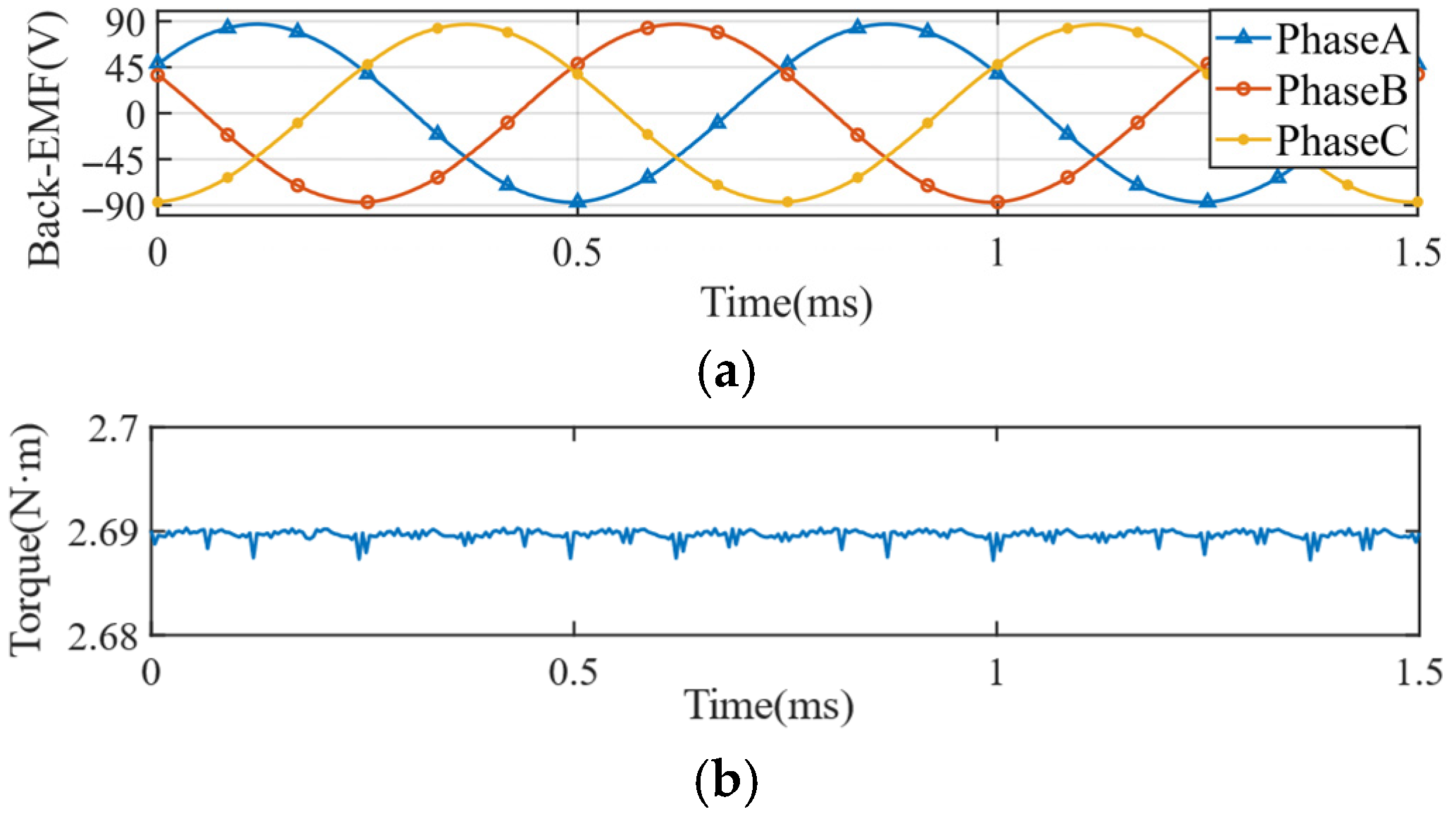
The maximum radial flux density is about 0.685 T, which is shown in Figure 6. The back-EMF wave is shown in Figure 7a. Since the radial magnetic flux density varies sinusoidally, its back-EMF also follows a sinusoidal pattern. The torque output of the HSSPMSM at rated speed is shown in Figure 7b when the maximum winding current is applied. The maximum output power of the HSSPMSM is about 10.5 kW, calculated by (7), which meets the 10 kW index requirement.
P o = T e n
where Te is the output torque of the HSSPMSM and n is the rotation speed of the HSSPMSM.
The electromagnetic loss characteristics affect the thermal performance of the motor. To achieve a low electromagnetic loss, A low-loss iron core material of 10JNEX900 is adopted. According to the magnetic flux density distribution in Figure 5, the iron core losses of the HSSPMSM at a speed of 40,000 rpm can be obtained, which is given in Table 3. Litz wire is used as the winding, which can mitigate eddy current losses and skin effects at high frequencies. Therefore, the copper loss can be calculated by (8).
P c = 3 I s 2 R s
where Is is the single-phase current and Rs is the stator resistance.

3.4. Airflow–Thermal Analysis of the HSSPMSM

The steady-state temperature of the HSSPMSM is calculated using a multiphysics coupling analysis method that combines electromagnetic, air-gap airflow, and thermal. The losses are the primary sources of heat, which have been listed in Table 3.
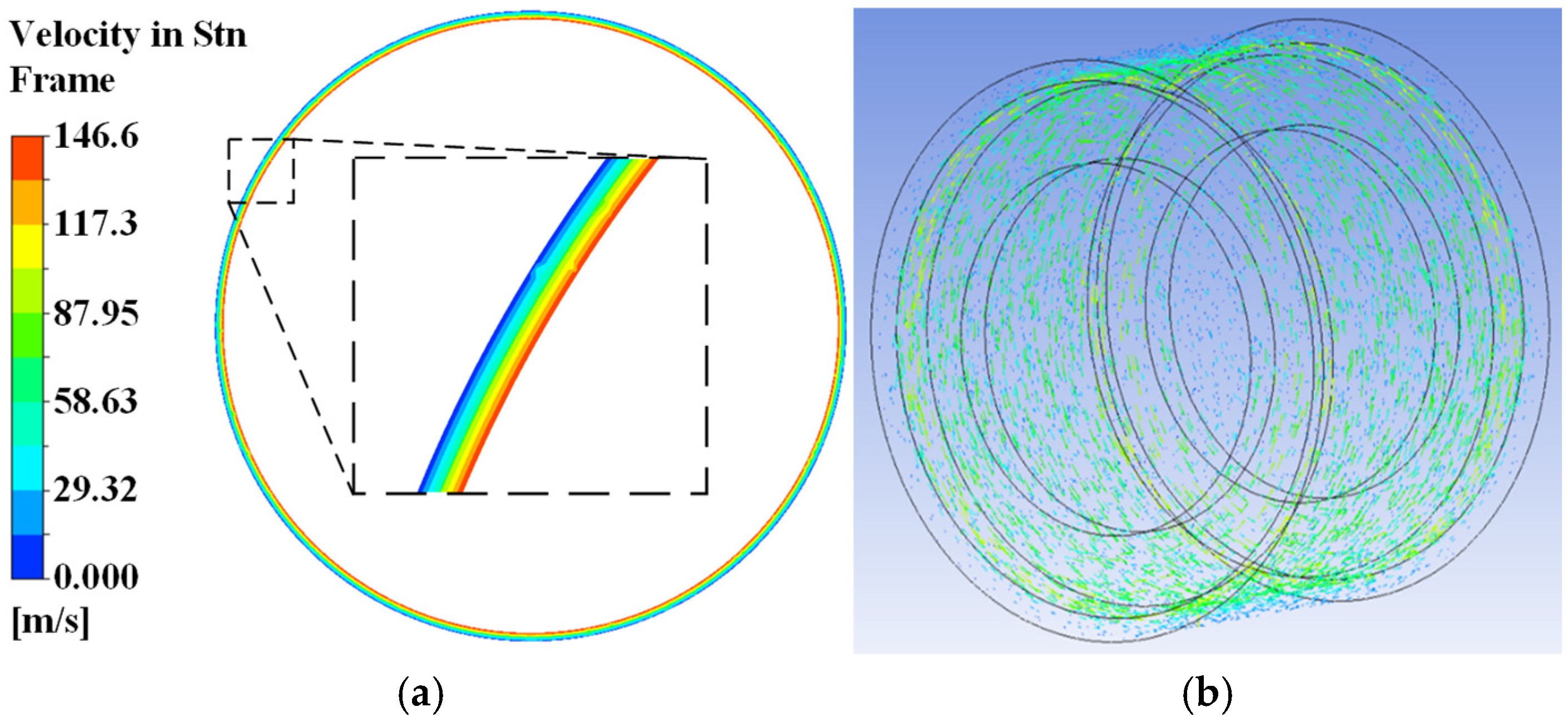
For the air-gap airflow analysis, a simplified computational fluid dynamics (CFD) model of the HSSPMSM is constructed in Figure 8. The model considers the inner face of the stator as the interface, and the motion fluid domain includes the rotor. The rotor rotation drives the airflow within the air gap. The interface between the motion and stationary fluid domains is set as an interface boundary, through which the two domains exchange data about velocity and pressure. The boundary face beside the outer surface is set as a moving wall, whose speed is relative to the adjacent cell zone [22].
The distribution of the air-gap airflow velocity is shown in Figure 9. The airflow velocity near the rotor side is the highest, approaching the linear speed of the rotor. In contrast, the velocity at the interface is virtually zero. The airflow velocities in the air gap of different rotation speeds are shown in Figure 10. The airflow velocity will affect the heat dissipation coefficient of the air. According to [23,24,25], the effective thermal conductivity of the air-gap airflow λa can be calculated as follows.
The Reynolds number Re in the air gap can be expressed as
R e = θ r δ υ
where θr is the circumferential velocity of the rotor, δ is the length of the air gap, and υ is the kinematic viscosity of the air.
The critical Reynolds number Recr can be expressed as
R ecr = 41.2   R i δ
where Ri is the inner radius of the interface.
According to (9), the Re is approximately 9733 when the HSSPMSM rotates at rated speed. According to (10), the Recr is approximately 254. The airflow in the air gap is the laminar flow when Re < Recr. Λa is equal to the thermal conductivity coefficient of air. The airflow in the air gap is turbulent when Re > Recr.
The λa can be expressed as
λ a = 0.069 r 0 R i 2.9084 Re 0.4614 ln 3.33361 η
where ro is the outer radius of the rotor.
With the air-gap airflow obtained, the thermal performance of the motor is further analyzed. The heat dissipation coefficient in the air gap is affected by the tangential motion of the rotor. Additionally, the inner surface of the stator contributes to this effect through its blocking action. The heat dissipation coefficient of the inner surface of the stator can be expressed as
a δ = 28 1 + v δ 0.5
The heat dissipation coefficients of the corresponding parts of the HSSPMSM for the natural cooling condition can be calculated [24]. The heat dissipation coefficient of the stator core end-face can be expressed as
α s = 1 + 0.04 υ 0.045
The heat dissipation coefficient of the rotor end-face can be expressed as
α r = 28 1 + 0.45 υ
The heat dissipation coefficient of the motor housing can be expressed as
α h = 14 3 T 0 25
According to (12), (13), (14), and (15), the heat dissipation coefficients can be obtained, which are listed in Table 4.
To solve the thermal distribution, it is necessary to set the thermal conductivity of the material in the finite element model. The thermal conductivities for materials of the HSSPMSM are shown in Table 5. By setting the heat sources in Table 3, the heat dissipation coefficients in Table 4, and the thermal conductivity coefficients in Table 5, the finite element analysis results of the thermal of the HSSPMSM can be obtained.
The temperature distribution of the HSSPMSM is shown in Figure 11. Figure 11a indicates that the maximum temperature of the housing reaches 55.735 °C. Figure 11b indicates that the maximum temperature of the stator is 56.766 °C. These temperatures are within the operational limits and will not affect the performance of the HSSPMSM. Therefore, the thermal design of the HSSPMSM meets the requirements.

3.5. Mechanical Strength Analysis of the HSSPMSM

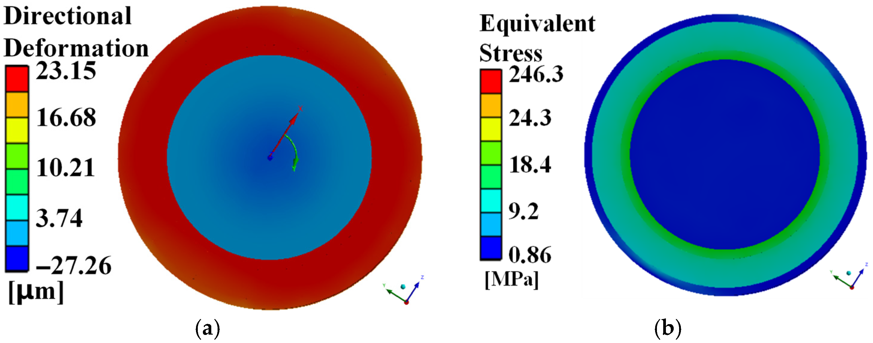
The rotor of the HSSPMSM is designed with an interference fit carbon fiber sleeve to prevent the Halbach array from deforming and breaking due to high-speed rotation. The two-dimensional (2D) model of the rotor is shown in Figure 12. The results of the mechanical strength analysis of the HSSPMSM are shown in Figure 13.
The maximum deformation of the Halbach array is about 23 μm, which is shown in Figure 13a, indicating that the Halbach array will not deform at rated speed. Figure 13b shows that the maximum equivalent stress of the rotor is 246.3 MPa, while the maximum equivalent stress of the Halbach array remains below 24.3 MPa. These stress calculations account for the influence of temperature on the Young’s modulus, with the simulation using the material’s Young’s modulus at the maximum operating temperature of the motor. The materials used in the rotor of the HSSPMSM include stainless steel and permanent magnet, with yield limits of 310 MPa and 30 MPa, respectively. Therefore, the used materials and the designed structure will not break at the rated speed. The structure of the HSSPMSM satisfies the mechanical strength requirements. Based on the above multiphysics analysis, the main parameters of the HSSPMSM are determined, which are listed in Table 6.

4. Experiment Verification

Based on the determined parameters, a 10 kW/40 krpm HSSPMSM is developed. The motor shaft is suspended by magnetic bearings to operate at the high speed of 40,000 rpm. The rotor and stator of the HSSPMSM are shown in Figure 14a,b. The HSSPMSM with the magnetic bearings is shown in Figure 14c. To verify the motor performance, the magnetic field, back-EMF, and temperature are measured.
A Hall sensor-based probe is developed to test the radial magnetic field of the air gap. The experimental setup of the HSSPMSM is shown in Figure 15. The thickness of the probe is only 0.3 mm, so it can fit into the 1 mm air gap. The probe will be crushed due to the extremely strong attraction between the rotor and the stator during the measurement. We inserted multiple gaskets with a thickness of 1 mm between the rotor and the stator to ensure the reliability of the data collected for the probe. Furthermore, to guarantee the precision of the measurement, the probe measures every 5° around the rotor, with each position being measured multiple times for consistency. The maximum radial flux density shown in Figure 16 is 0.633 T, with a relative error of 7.6%.
Furthermore, back-EMF is tested. The back-EMF for the no-load condition at the rated speed of the FEM is about 87 V, and that of the test is about 83 V, as shown in Figure 17. The relative error of the maximum back-EMF is 4.5%. The error is reasonable considering the error of the measurement and the FEM results. The output torque of the HSSPMSM is about 2.69 N∙m. According to (7), the output power is 10.37 kW, which meets the 10 kW index requirement. The experimental results illustrate that the designed HSSPMSM can meet the design requirements.
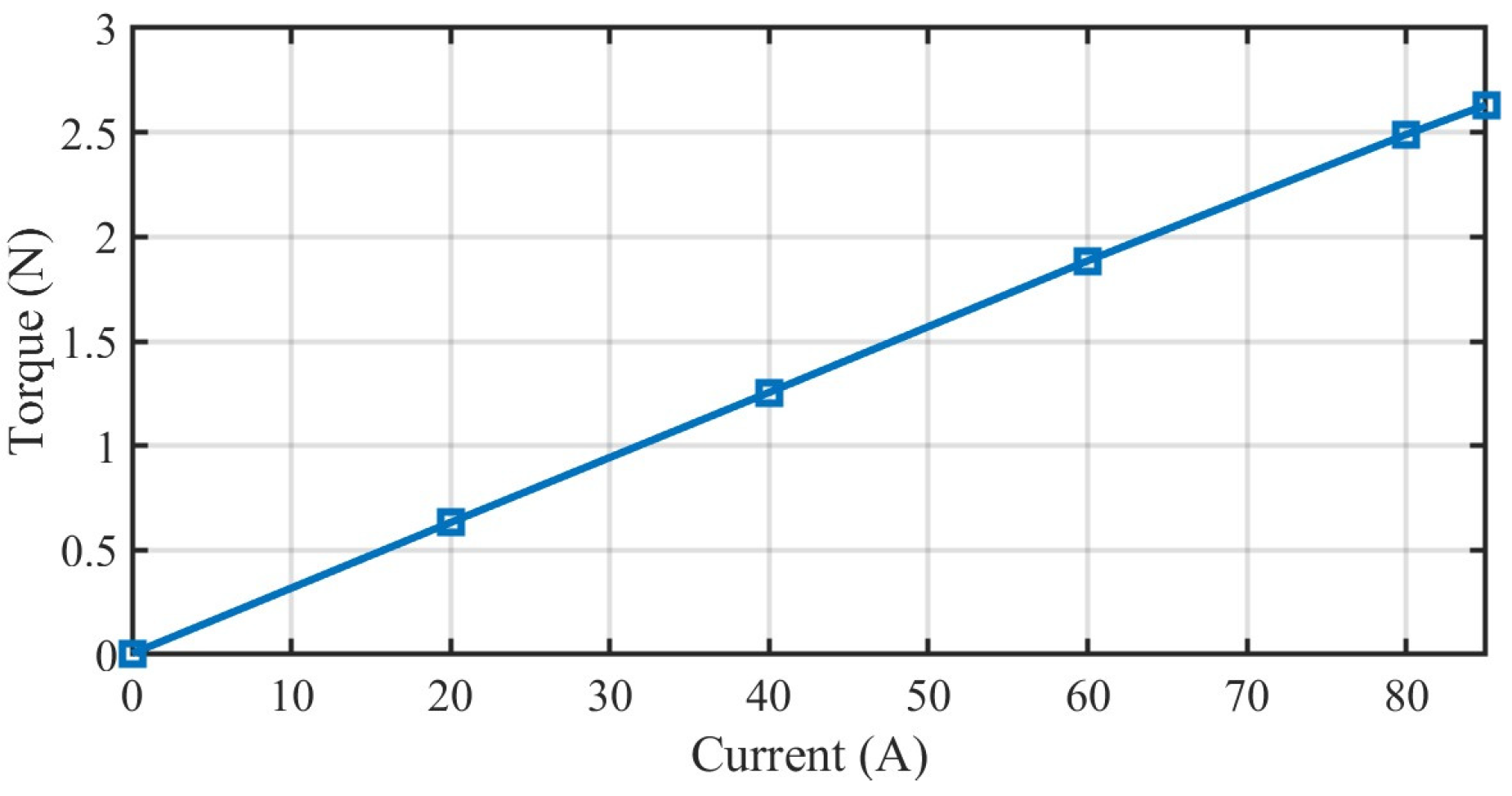
The torques of the HSSPMSM of different winding currents are measured by using a static torque sensor. The torque measurement results are shown in Figure 18. The measured torque of 85 A is 2.63 Nm, which matches the designed requirement of Table 1. From the FEM results of Figure 7, the simulation error is less than 4.1%.
According to Figure 3, the air-gap airflow directly affects the temperature, thereby affecting the electromagnetic and mechanical performance. Therefore, temperature measurement is conducted to verify that considering airflow analysis can obtain more accurate motor performance. The temperature distribution measurement result of the motor housing and the temperature distribution FEM results are shown in Figure 19. The maximum measurement temperature of the housing is 63.6 °C. The maximum temperature of the FEM considering air-gap airflow is 57.27 °C, with an error of less than 9.95%. The maximum temperature of the FEM without considering air-gap airflow is 75.32 °C, with an error larger than 18.4%. The experimental results indicate that considering air-gap airflow can obtain more accurate thermal analysis results and meet the requirements of motor design.
In addition, according to the temperature distribution results in Figure 19b, the temperature difference between the inside and outer of the motor is less than 1.55 °C. Therefore, the internal temperature of the motor will not exceed 70 °C, meeting the motor design requirements in Table 1.

5. Conclusions

This paper presents the design and analysis of a 10 kW/40 krpm HSSPMSM considering the influence of air-gap airflow. Through the electromagnetic analysis, airflow–thermal analysis, and mechanical strength analysis, the design parameters are determined. Based on the analysis results, the power, torque, temperature rise, and strength characteristics of the HSSPMSM meet the design requirements. Based on the determined parameters, a HSSPMSM prototype is developed, and the performance measurement experiments are conducted. The actual power can exceed the designed power by 3.7%. The error of the actual torque is 4.8% compared to the design torque. The error in the temperature results of FEM is 9.95%. The experimental results illustrate that the developed HSSPMSM satisfies the design requirements.

Author Contributions

Conceptualization, H.-J.H.; Data curation, Z.-Q.L.; Funding acquisition, G.-Z.C.; Investigation, H.-J.H.; Methodology, H.-J.H.; Software, M.-H.G.; Validation, H.-J.H. and S.-D.H.; Writing—original draft, H.-J.H.; Writing—review and editing, S.-D.H. and Z.-Q.L. All authors have read and agreed to the published version of the manuscript.

Funding

National Natural Science Foundation of China under Grant 52277061, 52450311; and Shenzhen Science and Technology Program, China, under Grant JCYJ20250604182631042, JCYJ20220818095804009.

Data Availability Statement

The data presented in this study are available on request from the corresponding author. The data are not publicly available due to the privacy agreement among co-authors.

Conflicts of Interest

The authors declare no conflicts of interest.

References

  1. Liu, G.W.; Liu, M.Y. High-speed permanent magnet synchronous motor iron loss calculation method considering multiphysics factors. IEEE Trans. Ind. Electron. 2020, 67, 5360–5368. [Google Scholar] [CrossRef]
  2. Li, X.; Dietz, D.; An, J. Manufacture and testing of a magnetically suspended 0.5-kWh flywheel energy storage system. IEEE Trans. Ind. Appl. 2022, 58, 6152–6162. [Google Scholar] [CrossRef]
  3. Hu, H.J.; Liu, K.; Wei, J.B.; Wang, H.Z. Multirate model predictive current control of a permanent magnet synchronous machine for a flywheel energy storage system. Energy Rep. 2022, 8, 11579–11591. [Google Scholar] [CrossRef]
  4. Wu, S.; Tian, C.; Zhao, W.; Zhou, J.; Zhang, X. Design and Analysis of an Integrated Modular Motor Drive for More Electric Aircraft. IEEE Trans. Transp. Electrif. 2020, 6, 1412–1420. [Google Scholar] [CrossRef]
  5. Cao, W.; Mecrow, B.C.; Atkinson, G.J.; Bennett, J.W.; Atkinson, D.J. Overview of Electric Motor Technologies Used for More Electric Aircraft (MEA). IEEE Trans. Ind. Electron. 2012, 59, 3523–3531. [Google Scholar]
  6. Wang, J.; Li, Y.; Han, Y. Integrated Modular Motor Drive Design with GaN Power FETs. IEEE Trans. Ind. Appl. 2015, 51, 3198–3207. [Google Scholar] [CrossRef]
  7. Shen, Q.P.; Zhou, Z.Y.; Li, S.; Liao, X.L.; Wang, T.; He, X.R.; Zhang, J.S. Design and analysis of the high-speed permanent magnet motors: A review on the state of the art. Machines 2022, 10, 549. [Google Scholar] [CrossRef]
  8. Yang, H.D.; Chen, Y.S. Influence of radial force harmonics with low mode number on electromagnetic vibration of PMSM. IEEE Trans. Energy Convers. 2014, 29, 38–45. [Google Scholar] [CrossRef]
  9. Rodríguez, A.L.; Gómez, D.J.; Villar, I.; López-de-Heredia, A.; Etxeberria-Otadui, I. Improved analytical multiphysical modeling of a surface PMSM. In Proceedings of the 2014 International Conference on Electrical Machines (ICEM), Berlin, Germany, 2–5 September 2014. [Google Scholar]
  10. Jannot, X.; Vannier, J.C.; Marchand, C.; Gabsi, M.; Saint-Michel, J.; Sadarnac, D. Multiphysic Modeling of a High-Speed Interior Permanent-Magnet Synchronous Machine for a Multiobjective Optimal Design. IEEE Trans. Energy Convers. 2011, 26, 457–467. [Google Scholar] [CrossRef]
  11. Bang, T.K.; Shin, K.H.; Lee, J.I.; Cho, H.W.; Choi, J.Y. Electro-mechanical characteristics analysis and experimental study of PMSM according to rotor eccentricity. IEEE Trans. Magn. 2022, 58, 8103205. [Google Scholar] [CrossRef]
  12. Akiki, P. Multiphysics Design of a V-Shape IPM Motor. IEEE Trans. Energy Convers. 2018, 33, 1141–1153. [Google Scholar] [CrossRef]
  13. Islam, M.K.; Tasnim, K.N.; Choi, S.; Kwak, S.; Arafat, A. Designing High-Power Ultra-High-Speed Motor Using a New Multiphysics Multi-Objective Optimization Method for Mechanical Antenna Applications. IEEE Access 2022, 10, 106305–106323. [Google Scholar] [CrossRef]
  14. Popescu, M.; Foley, I.; Staton, D.A.; Goss, J.E. Multi-physics analysis of a high torque density motor for electric racing cars. In Proceedings of the 2015 EEE Energy Conversion Congress and Exposition (ECCE), Montreal, QC, Canada, 20–24 September 2015. [Google Scholar]
  15. Zhao, W.D.; Wang, X.J.; Gerada, C.; Zhang, H.; Liu, C.A.; Wang, Y.L. Multi-physics and multi-objective optimization of a high speed PMSM for high performance applications. IEEE Trans. Magn. 2018, 54, 8106405. [Google Scholar] [CrossRef]
  16. Sun, X.; Wan, B.; Lei, G.; Tian, X.; Guo, Y.; Zhu, J. Multiobjective and Multiphysics Design Optimization of a Switched Reluctance Motor for Electric Vehicle Applications. IEEE Trans. Energy Convers. 2021, 36, 3294–3304. [Google Scholar] [CrossRef]
  17. Vansompel, H.; Leijnen, P.; Sergeant, P. Multiphysics analysis of a stator construction method in yokeless and segmented armature axial flux PM machines. IEEE Trans. Energy Convers. 2019, 34, 139–146. [Google Scholar] [CrossRef]
  18. Sun, M.X.; Xu, Y.L.; Zhang, W.J. Multiphysics analysis of flywheel energy storage system based on cup winding permanent magnet synchronous machine. IEEE Trans. Energy Convers. 2023, 38, 2684–2694. [Google Scholar] [CrossRef]
  19. Song, Z.X.; Liu, C.H.; Feng, K.; Zhao, H.; Yu, J.C. Field prediction and validation of a slotless segmented-Halbach permanent magnet synchronous machine for more electric aircraft. IEEE Trans. Transp. Electrif. 2020, 6, 1577–1591. [Google Scholar] [CrossRef]
  20. Lee, D.S.; Balachandran, T.; Sirimanna, S.; Salk, N.; Yoon, A.; Xiao, P.; Macks, J.; Yu, Y.X.; Liu, S.N.; Schuh, J.; et al. Detailed design and prototyping of a high power density slotless PMSM. IEEE Trans. Ind. Appl. 2023, 59, 1719–1727. [Google Scholar] [CrossRef]
  21. Wu, L.; Zhu, Z. Analytical Modeling of Surface-Mounted PM Machines Accounting for Magnet Shaping and Varied Magnet Property Distribution. IEEE Trans. Magn. 2014, 50, 8101511. [Google Scholar] [CrossRef]
  22. Li, L.; Sun, Z.; Huang, X.; Cao, J. Thermal analysis of high speed motor based on flow field calculation considering tooth-slots effects. In Proceedings of the 2011 International Conference on Electrical Machines and Systems, Beijing, China, 20–23 August 2011. [Google Scholar]
  23. Xyptras, J.; Hatziathanassiou, V. Thermal analysis of an electrical machine taking into account the iron losses and the deep-bar effect. IEEE Trans. Energy Convers. 1999, 14, 996–1003. [Google Scholar] [CrossRef]
  24. Hatziathanassiou, V.; Xypteras, J.; Archontoulakis, G. Electrical-thermal coupled calculation of an asynchronous machine. Arch. Elektrotech. 1994, 77, 117–122. [Google Scholar] [CrossRef]
  25. Ghahfarokhi, P.S.; Podgornovs, A.; Kallaste, A.; Cardoso, A.J.M.; Belahcen, A.; Vaimann, T.; Asad, B.; Tiismus, H. Determination of heat transfer coefficient from housing surface of a totally enclosed fan-cooled machine during passive cooling. Machines 2021, 9, 120. [Google Scholar] [CrossRef]
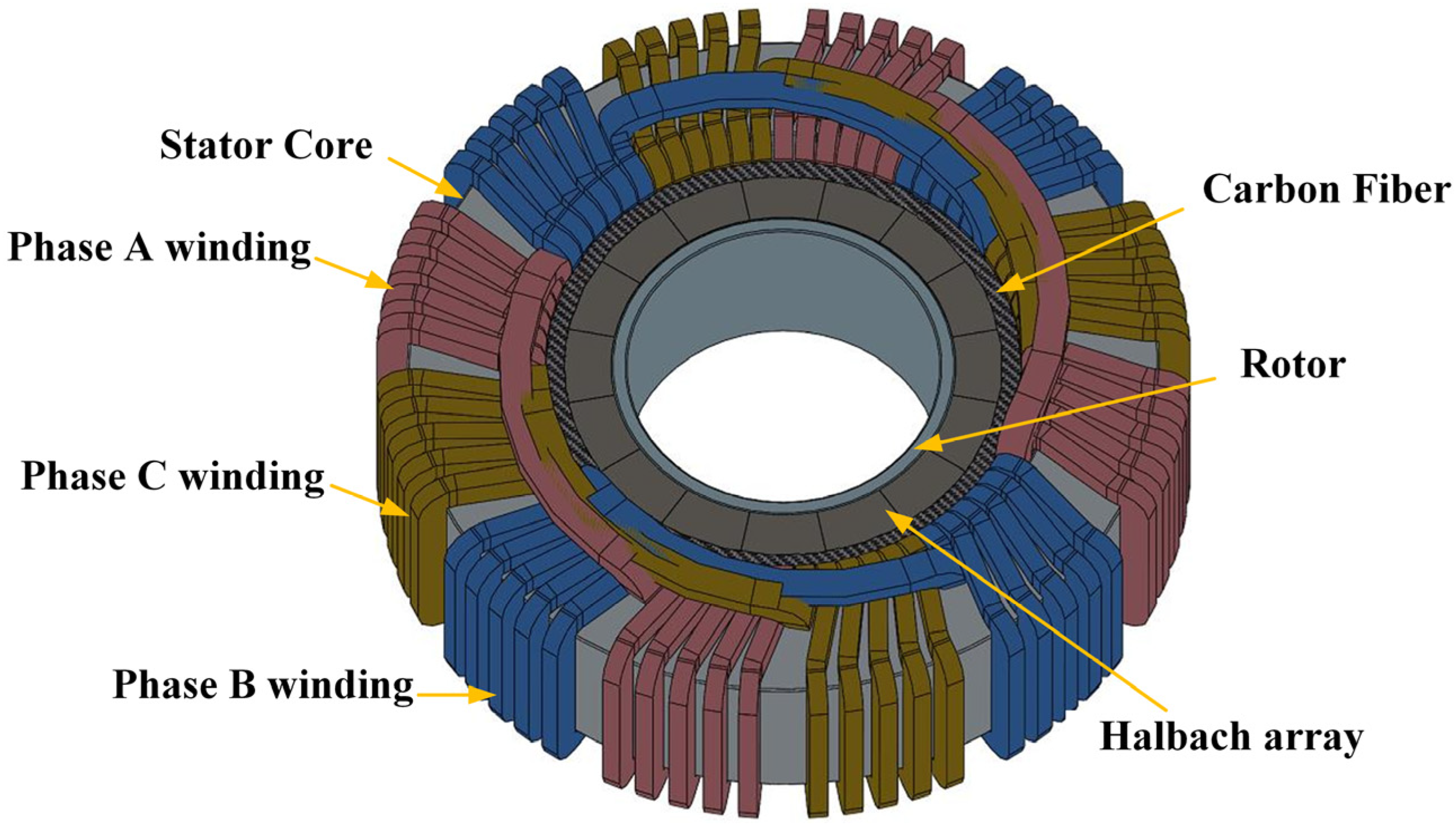
Figure 1. The structure of the HSSPMSM.
Actuators 14 00530 g001
Figure 2. The coupling relationships between multiple physical fields in HSSPMSM.
Actuators 14 00530 g002
Figure 3. The flowchart of the HSSPMSM design.
Actuators 14 00530 g003
Figure 4. The polar coordinate diagram of the HSSPMSM.
Actuators 14 00530 g004
Figure 5. The magnetic field of the HSSPMSM. (a) Magnetic flux density distribution; (b) Magnetic vector potential distribution.
Actuators 14 00530 g005
Figure 6. The air-gap radial flux density waveform.
Actuators 14 00530 g006
Figure 7. The transient electromagnetic analysis results at the rotation speed of 40,000 rpm. (a) The back-EMF. (b) The output torque of the HSSPMSM.
Actuators 14 00530 g007
Figure 8. The simplified model of the HSSPMSM for CFD.
Actuators 14 00530 g008
Figure 9. The flow field distribution in the air gap for the rotation speed of the HSSPMSM is 40,000 rpm. (a) Air-gap flow velocity. (b) The 3D flow field.
Actuators 14 00530 g009
Figure 10. The airflow velocity in the air gap at different rotation speeds of the HSSPMSM.
Actuators 14 00530 g010
Figure 11. The thermal analysis results for the natural cooling condition. (a) Heat distribution of the motor housing. (b) Heat distribution of the stator.
Actuators 14 00530 g011
Figure 12. The 2D model of the rotor.
Actuators 14 00530 g012
Figure 13. The results of the mechanical strength analysis. (a) The directional deformation of the rotor. (b) The equivalent stress of the rotor.
Actuators 14 00530 g013
Figure 14. The prototype of the HSSPMSM. (a) The rotor. (b) The stator. (c) HSSPMSM with magnetic bearings.
Actuators 14 00530 g014
Figure 15. The experimental setup of the HSSPMSM.
Actuators 14 00530 g015
Figure 16. The comparison of the radial flux density.
Actuators 14 00530 g016
Figure 17. The comparison of the back-EMF.
Actuators 14 00530 g017
Figure 18. The measured torque versus winding current of the HSSPMSM.
Actuators 14 00530 g018
Figure 19. The temperature distribution of the motor housing and comparison with the FEM results. (a) The temperature measurement result of the motor housing. (b) FEM result considering air-gap airflow. (c) FEM result without considering the air-gap airflow.
Actuators 14 00530 g019
Table 1. Design requirements of the HSSPMSM.
ParameterDescriptionValue
PNrated power>10 kW
nNrated speed>40,000 rpm
Immaximum winding current<85 A
Temaximum output torque>2.5 N∙m
Tomaximum allowable operating temperature<70 °C
UdcDC supply voltage<110 V
Table 3. Losses of the HSSPMSM at rated speed.
ParameterDescriptionValue
Piiron core loss26.31 W
Pccopper loss300 W
Table 4. Heat dissipation coefficients of the components.
ParameterDescriptionValue
αδthe inner surface of the stator241.35 W/m2·°C
αsthe end-face of the rotor22.22 W/m2·°C
αrthe end-face of the stator28.07 W/m2·°C
αhthe outer surface of the housing22.00 W/m2·°C
Table 5. Thermal conductivities of the materials used in HSSPMSM.
ComponentMaterialValue
iron core10JNEX90011.6 W/m·°C
windingcopper396.7 W/m·°C
motor housingaluminum alloy160 W/m·°C
air gapair0.025 W/m·°C
Halbach arrayN45UH7 W/m·°C
rotorstainless steel16.3 W/m·°C
rotorelectrical pure iron of steel 100836 W/m·°C
insulationthermal glue1.2 W/m·°C
Table 6. Main dimensions of the HSSPMSM.
ParameterDescriptionValue
npnumber of pole pairs2
Riradius of the main shaft25 mm
Rmiinner radius of the Halbach array27.5 mm
Rmoouter radius of the Halbach array35 mm
Roinner radius of the stator42 mm
δlength of the air gap3.5 mm
Brremanence1.358 T
Table 2. Initial dimensions and magnetization parameter of the HSSPMSM.
ParameterDescriptionValue
npnumber of pole pairs2
Riradius of the main shaft24 mm
Rmiinner radius of the Halbach array28 mm
Rmoouter radius of the Halbach array35 mm
Roinner radius of the stator42 mm
δlength of the air gap3.5 mm
Brremanence1.358 T
Disclaimer/Publisher’s Note: The statements, opinions and data contained in all publications are solely those of the individual author(s) and contributor(s) and not of MDPI and/or the editor(s). MDPI and/or the editor(s) disclaim responsibility for any injury to people or property resulting from any ideas, methods, instructions or products referred to in the content.