Abstract
Nowadays, grippers are extensively employed to interact with dynamic and variable objects. Therefore, enhancing the adaptability of grippers is crucial for improving production efficiency and product quality. To address the trade-off between load capacity and interaction safety in rigid and soft grippers, this paper proposes a rigid–flexible coupling gripper with high grasping adaptability based on an underactuated structure. We conduct static analysis on the underactuated mechanism, followed by dimensional optimization using a genetic algorithm. After optimization, the grasping force error at each knuckle is reduced to 2 N, and the total grasping force reaches 38 N. The soft actuators, integrated with a rigid framework, not only increase the contact area during grasping but also mitigate the excessive concentration of contact forces, significantly improving the compliance of the gripper. Additionally, to tackle the issue of weak interfacial bonding strength caused by rigidity mismatch between rigid components and soft materials, this paper proposes a novel method of applying embedded microstructures to enhance the interfacial toughness of rigid–flexible coupling. The elastic deformation of these microstructures ensures strong interfacial connection strength both under tensile and shear stresses. Lastly, a robotic grasping platform is developed to carry out diverse grasping experiments. Experimental results show that the underactuated linkage mechanism and the flexible structure can collaboratively adjust grasping strategies when handling objects of various types, enabling stable manipulation while preventing object damage. This design effectively expands the operational applicability of the gripper.
1. Introduction
As a core component of robotic systems, grippers are indispensable in fields such as automated production, healthcare, flexible manufacturing, and human–computer interaction [1,2]. To handle diverse tasks and interact with various objects, grasping adaptability is a crucial metric for evaluating gripper performance. The high inherent elastic modulus of traditional rigid grippers [3] poses potential safety risks [4], including irreversible damage to delicate objects such as human organs [5], which severely limits their applications. Soft grippers, fabricated from compliant materials [6,7,8], can conform to objects of various shapes and sizes [9] and achieve adaptive grasping via simple control strategies [10]. However, material limitations result in inherent drawbacks, such as low payload capacity and insufficient gripping force [11], which remain primary bottlenecks limiting the broader application of soft robots [6]. To overcome the limitations of single-material systems and enhance grasping adaptability, rigid–flexible coupling grippers have been developed. These systems synergistically integrate the structural robustness of rigid materials with the high deformability of soft materials [12,13,14], thereby providing exceptional adaptability, inherent safety, and high load-bearing capacity [15,16,17].
Underactuated structures can effectively improve the gripping adaptability of robotic grippers. Sarah [18] develops a gripper based on an underactuated structure, which addresses some issues with multi-jointed grippers, such as multiple power sources, control difficulties, and complex structures. During the grasping process, the gripper can achieve adaptive enveloping of the object using a single motor. This structure significantly enhances the gripper’s grasping capability. Sun [19] designs an underactuated robotic hand with a simple structure and strong versatility based on the principle of the metamorphic mechanism. However, rigid contact still has significant limitations when grasping soft and fragile objects. Flexible robotic hands are limited by the properties of soft materials and generally suffer from the problem of weak load-carrying capacity. Abondance [20] designs a four-fingered soft robotic hand, whose maximum payload is limited to 0.47 kg. Similarly, Wei [21] develops a three-fingered soft gripper with maximum grasping capacity of only 0.74 kg. Wang [22] designs a humanoid hand suitable for daily grasping, which can simulate various grasping actions of the human hand, but it can only grasp a chair weighing up to 0.54 kg. Qi [23,24] uses shape memory alloy materials and 4D printing technology to produce a gripper for manipulating lightweight objects such as nuts. Xie [25] designs a bio-inspired robotic hand based on the suction principles of octopus arms, with its maximum payload capped at 500 g. Therefore, rigid or flexible robotic hands, when based on a single-material system, have trade-offs in performance in terms of stiffness, compliance, load-carrying capacity, and adaptability, which makes it difficult to meet diverse grasping requirements.
To break through this bottleneck, the rigid–flexible coupling gripper integrates the complementary advantages of rigid and flexible materials to enable diverse actuation strategies [26]. Su [27] proposes an elastic band-driven rigid–flexible coupling (SAU-RFC) manipulator that offers good compliance. However, the same flexible straps are used for both actuation and object contact. Tang [28] presents a monostable rigid–flexible coupling manipulator actuated by springs serving as tendons. Although the hand can safely pinch an egg and lift a dumbbell weighing up to 11.4 kg, each tendon requires a separate actuation source. Liu [29] develops a motor-driven three-fingered manipulator for adaptive grasping. However, due to its high proportion of flexible materials, its load-bearing capacity needs to be improved. Additionally, the significant difference in elastic moduli between rigid and flexible materials complicates their effective coupling. Guo [30] introduces a rigid–flexible coupling manipulator featuring a parallel configuration of an exoskeleton and a soft actuator. This design significantly enhances load-bearing capacity while maintaining compliance but does not solve the interfacial coupling issue at the interface between the rigid and flexible materials. Zhu [31] achieves coupling between rigid and flexible structures using simple bolted connections. The interaction between the rigid and flexible parts enables the gripper to achieve multi-modal, multi-posture grasping capabilities. However, the rigidity mismatch between the materials makes the connection interface prone to failure due to slipping.
In summary, rigid or flexible grippers struggle to adapt to diverse environments. Coupling rigid and flexible structures can endow grippers with both adaptability and safety, significantly broadening their application scope. Nevertheless, existing rigid–flexible coupling grippers face issues such as complex structures, low load-carrying capacity, and interface failure due to slipping. To address these issues, this paper proposes an underactuated rigid–flexible coupling gripper with high grasping adaptability. Through theoretical analysis and simulations, we investigate the static model of the underactuated structure, the toughening effect of flexible microstructures on the rigid–flexible coupling interface, and the inflation behavior of the soft actuator. Combined with grasping experiments, we demonstrate that the gripper has high grasping adaptability.
2. Materials and Methods
2.1. Materials
Ecoflex™00–30 silicone (a two-part addition-cure platinum-catalyzed silicone elastomer; shore hardness: 00–30, mixing ratio 1A:1B by weight) was purchased from Smooth-On, Inc. located in Macungie, PA, USA, through an authorized supplier on Taobao. The liquid precursor components (Part A and Part B) were used as received, without further pretreatment. Photopolymer resin (acrylic-based; λ~405 nm; tensile strength: 40–50 MPa; viscosity: 300–500 cP) was procured from a third-party f manufacturer through Taobao. The resin was employed as received and processed under standard curing conditions (405 nm UV light, 10 mW/cm2, 60 s).
2.2. Fabrication of Rigid–Flexible Coupling Gripper
Before fabrication, we assemble the 3D-printed mold. We then mix the liquid components A and B of Ecoflex™00–30 silicone at a 1:1 ratio (by volume or weight), pour the mixture into a container, stir it uniformly at 25 °C, and then perform vacuum degassing to remove internal bubbles, resulting in the liquid silicone.
First, we prepare the flexible plug and soft actuator, pour the prepared silicone into the mold, allowing it to cure at room temperature, and then demold the parts. Next, we assemble the prepared flexible plug within the 3D-printed mold. After that, we slowly pour the mixed liquid silicone into this assembled mold, specifically into the cavity with pores for embedding microstructures. We allow the mixed liquid silicone to flow into the pores of the porous plate and fill them completely. Before the liquid silicone is fully cured, we press the cavity side of the soft actuator firmly against the partially cured embedded microstructures. Once the liquid silicone is fully cured, the soft actuators form a tight bond with the embedded flexible microstructures, resulting in an integrated rigid–flexible coupling structure comprising the rigid porous connecting plate, the flexible microstructure, and the soft actuator.
2.3. Grasping Experiment
After the gripper is mounted on the 3D motion platform, the X-, Y-, and Z-axis motors of the platform are controlled to position the gripper relative to the target. Subsequently, the internal motor of the gripper is activated to move the three fingers closer to the target object. The underactuated structure adaptively adjusts its grasping posture based on the target object: when grasping tofu and cabbage, the gripper adopts a pinching posture, where the distal phalanges of the gripper make direct contact with the object. Both the tofu and cabbage, as well as the soft actuator, undergo deformation due to compression; thereafter, the Z-axis motor of the motion platform is controlled again to complete the grasping process.
When grasping cauliflower and instant noodles, the gripper employs an enveloping posture. With the gripper motor operating, the proximal phalanges, middle phalanges, and distal phalanges sequentially come into tight contact against the object, thereby achieving enveloping grasping. The compressive deformation of the soft actuator not only ensures the necessary friction force for grasping tofu but also prevents damage to the tofu surface during the grasping process.
3. Finite Element Modeling (FEM)
We selected the C3D10M element for simulation due to its high efficiency and accuracy. In the simulation of embedded microstructures, the hyperelastic behavior of the silicone rubber is defined using the Mooney–Rivlin model. Its density is set to 1030 kg/m3, with parameters C10 = 0.152, C01 = 0.038, and D1 = 0. The material for the lower layer is defined as Q235 steel, with a density of 7860 kg/m3, a Young’s modulus of 208 GPa, and a Poisson’s ratio of 0.277. Due to the large deformations expected in the silicone rubber, a dynamic explicit analysis step is employed, with geometric nonlinearity enabled. The analysis time is set to 20 s, and mass scaling is applied to improve computational efficiency. A general contact interaction property is defined. Normal behavior is set to “Hard” contact, and the tangential behavior is defined, with a friction coefficient of 0.2.
In the simulation of the soft actuator, the temperature is set to 25 °C to simulate the performance under normal temperature conditions, and the inflation time is set to 0.1 s to replicate the rapid inflation process; for the contact between the finger surface and the target object, normal contact is defined as hard contact, and the friction coefficient for tangential contact is set to 0.2. The simulation process is divided into two steps: the first step focuses on inflation simulation, where the soft actuator expands gradually as the pressure inside the fluid cavity increases, and the second step involves the grasping process: after the soft actuator is fully inflated, the target object is simulated to approach the finger and come into contact with the soft actuator, with the primary goal of observing the variation patterns of contact force and contact area with the applied air pressure.
4. Results and Discussions
4.1. Design and Preparation of Rigid–Flexible Coupling Gripper
4.1.1. Structure Design of the Rigid–Flexible Coupling Gripper
To address current challenges in gripper design, such as limited load-bearing capacity, insufficient dexterity, and a narrow range of applications, this paper proposes an underactuated rigid–flexible coupling gripper. Driven by a single leadscrew motor, the gripper uses three underactuated fingers to achieve dexterous grasping motions, resulting in a compact overall structure and high operational flexibility. The rigid segment of each finger incorporates an underactuated linkage mechanism, which enables the leadscrew motor to actuate the proximal, middle, and distal phalanges during grasping. The flexible segment is fabricated via silicone casting technology and integrates the soft actuator with embedded flexible microstructures. These features not only significantly improve grasping compliance but also effectively enhance the toughness of the rigid–flexible material coupling interface.
As shown in Figure 1a, the model of the rigid–flexible coupling gripper consists of three main assemblies: three equally spaced rigid–flexible coupling fingers (Part 1), a load-bearing suspension frame (Part 2), and an actuation mechanism (Part 3). The fingers (Part 1) are secured to the base of the suspension frame (Part 2). The actuation mechanism (Part 3), which employs a leadscrew motor, is centrally mounted on the base of the suspension frame (Part 2) and drives all three fingers (Part 1) simultaneously. Figure 1b provides an exploded view of a single rigid–flexible coupling finger (Part 1), which is composed of an underactuated linkage mechanism, soft actuators, and embedded flexible microstructures. The underactuated linkage mechanism consists of linkages, triangular plates, and connection plates. The connection plates are located on the grasping side of each phalanx and have an internally hollow structure with multiple small holes on their contact surfaces. These holes allow for the integrated casting of the embedded flexible structure, thereby facilitating effective coupling between the rigid and flexible components. The soft actuator contains internal cavities and interconnecting air channels, whose inflation can be controlled via pneumatic pressure to enhance grasping compliance. Additionally, as shown in the inset at the bottom right of Figure 1b, flexible microstructures are embedded within the rigid connection plates of the underactuated mechanism to achieve material coupling and improve the toughness of the interface connection.
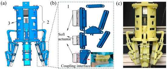
Figure 1.
The rigid–flexible coupling gripper. (a,b) The structure of the rigid–flexible coupling gripper. (c) The photo of the rigid–flexible coupling gripper.
The load-bearing suspension frame (Part 2) comprises a flange, support brackets, and a palm base. These rigid components are bolted together, with the flange serving as the interface between the gripper and the motion platform. The palm base accommodates the rigid–flexible coupling fingers, and its internal cavity houses the leadscrew drive assembly. A connecting rod transmits the grasping force and motion from the leadscrew slide to the three fingers. Both the rigid and flexible components of the gripper were fabricated using molds produced via 3D printing with photosensitive resin. Figure 1c shows a physical prototype of the rigid–flexible coupling gripper, which exhibits a compact structural design and demonstrates successful integration between the rigid and flexible parts.
4.1.2. Integrated Preparation Process of the Rigid–Flexible Coupling Gripper
The fabrication of the rigid–flexible coupling gripper consists of three main stages: manufacturing the rigid components, producing the flexible components, and achieving integrated coupling between the rigid and flexible parts. The rigid components are fabricated from photosensitive resin via 3D printing technology. The printed structures are assembled via standard bolted connections. Coupling between the rigid and flexible components is achieved through integrated casting, a process that forms the embedded microstructures. This process eliminates the need for post-assembly steps, features a simple molding process, and ensures high toughness at the coupling interface.
The detailed preparation process of the flexible components is illustrated in Figure 2. As shown in Figure 2a, which outlines the fabrication procedure, the flexible parts consist of the soft actuator (1) and a flexible plug (2). The soft actuator contains an internal cavity and air holes. When pressurized, the internal cavity expands and deforms, while the air holes are designed to allow silicone air tubes to be inserted. During casting, 3D-printed cylindrical rods are placed at the positions corresponding to the air holes of the soft actuator. After the silicone is cured and the mold is removed, the rods are extracted, leaving behind a soft actuator component with air passages and an internal cavity.
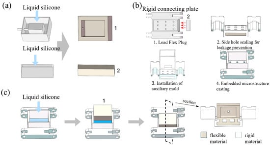
Figure 2.
Preparation process. (a) Preparation of flexible components. (b) Assembly process of the mold for the embedded microstructure. (c) The integrated casting process for the entire flexible structure.
The flexible plug (2) is a rectangular strip with the same dimensions as the hollow structure of the rigid connecting plate. It is used in subsequent steps to prevent liquid silicone from leaking during the casting of the embedded microstructures.
Figure 2b shows the mold assembly process for the embedded microstructure. Four 3D-printed auxiliary molds (plate structures) with snap-fit ends are installed into the grooves of the connecting plate. This internal mold assembly is used to contain the liquid silicone during casting. The mixed liquid silicone is then poured into the assembled mold. Prior to curing, silicone infiltrates the internal cavity of the porous connecting plate through its holes under gravity. The flexible plug and auxiliary molds effectively prevent leakage. After curing at room temperature and demolding, the embedded microstructure is fully formed.
Since the rigid porous connecting plate is part of the underactuated rigid structure, this casting process enables integrated manufacturing of the rigid and flexible components without requiring additional assembly. The deformable, embedded flexible microstructure enhances the toughness of the rigid–flexible coupling interface.
Figure 2c depicts the overall integrated casting process of the flexible structure. First, the mixed liquid silicone is poured into the combined mold corresponding to the embedded microstructures. The silicone flows into and fills the pores of the porous plate. Before the silicone is fully cured, the cavity side of the pre-cast soft actuator (1) is pressed firmly against the partially cured embedded microstructures. As both are made of the same material, they bond tightly after full curing, resulting in an integrated rigid–flexible composite structure: rigid porous connecting plate, flexible microstructures, and the soft actuator.
As shown in Figure 3a, the physical components of the 3D-printed mechanical finger comprise the linkage structures of each phalanx, fixed triangular plates, and connecting plates (the porous structures are used for forming the embedded microstructures). The linkages are designed in an H-shape to avoid compromising the 3D-printed mechanisms as a result of bolted connections, for example, the seizure of kinematic pairs due to excessive fastening tightness, since the roughness of 3D-printed parts is difficult to control precisely. The length of the H-shaped slot is determined through geometric design to ensure that the finger joints can only rotate toward the grasping side. Figure 3b shows the physical preparation of the flexible structure. The soft actuator is equipped with air holes for connecting silicone air tubes. Figure 3c presents the assembled three-phalanx rigid–flexible coupling finger, in which the rigid components are bolted together. The deformation of the soft actuator is controlled via silicone air tubes.
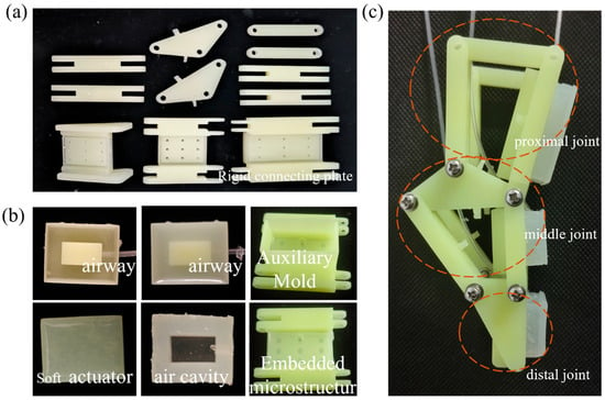
Figure 3.
The photos of mechanical finger. (a) The rigid underactuated structure parts. (b) The soft parts of the rigid–flexible coupling gripper. (c) The photos of the assembled three-knuckle rigid–flexible coupling gripper.
4.2. Statics Analysis of Underactuated Structures
The rigid–flexible coupling finger proposed in this paper is a multi-phalanx underactuated mechanism in which a single actuator controls the motion of the proximal, middle, and distal phalanges. To ensure the uniform distribution of grasping forces among the phalanges and avoid unstable grasping or object damage caused by excessive local forces, this section presents a detailed analysis of the effects of driving torque and underactuated linkage dimensions on the grasping force under different grasping postures. The dimensions of the underactuated linkages are optimized using a genetic algorithm.
4.2.1. Fingertip Gripping Contact Force Model
Fingertip pinch grasping employs the distal phalanx to grip objects, mimicking the pinching motion of a human hand. In this grasping configuration, the three underactuated phalanges can be treated as a single rigid body. Under ideal conditions, the static model of the fingertip contact force during pinching is derived using moment equilibrium:
In the formula: Ta1is the driving torque applied to the connecting rod a1; l1 and l2 are the lengths of the proximal and middle knuckles, respectively; f3 is the contact force at the fingertip; k3 is the distance from the fingertip contact point to the joint; and θ1 is the joint rotation angle of the proximal phalange. When the driving torque remains constant, the contact force during fingertip grasping is mainly affected by the joint rotation angle θ1 of the proximal phalange. Since underactuated grippers often use envelope contact to achieve grasping actions, the fingertip contact model is not discussed in detail here.
4.2.2. Envelope Contact Force Model
During enveloping grasping, each phalanx of the underactuated finger contacts the object. As shown in Figure 4a, a schematic of the multi-phalanx underactuated structure, the mechanism consists of links 1, 2, 4, 6, and 7, along with triangular plates 3 and 5, where link 7 serves as the driving link.
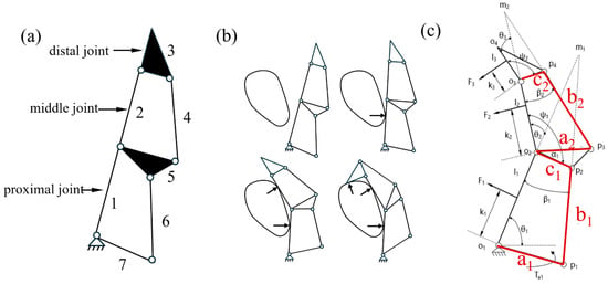
Figure 4.
The simplified diagram of underactuated structure. (a) Multi-kunckle underactuated finger simplified structure. (b) The grasping principle for the underactuated structure. (c) The static model for the multi-knuckle underactuated structure.
The working principle of the underactuated structure performing adaptive enveloping grasping is illustrated in Figure 4b. Initially, the three phalanges remain relatively stationary. Under driving torque, the finger rotates around the fixed base and approaches the target object. When the proximal phalanx contacts the object, the object applies a constraint to it. At this stage, the middle and distal phalanges rotate together around the joint of the proximal phalanx. Once the middle phalanx contacts the object and introduces a second constraint, the distal phalanx continues to rotate around the joint of the middle phalanx until the enveloping grasp is fully achieved.
Figure 4c shows the schematic diagram of the static model for the multi-knuckle underactuated structure. Based on the principle of virtual work (which states that the work performed by the driving force on virtual displacements equals the work performed by the output force on virtual displacements), the relationship between the input torque T at each joint of the finger and the output force F on each phalanx segment can be derived as follows:
In the formula, T is the input torque vector of each knuckle; is the angular velocity vector at the corresponding joint; F is the output force vector of the three knuckles when grasping; and is the virtual velocity vector in the direction of the external forces. The expressions of each vector above are as follows:
In the formula, is the input torque acting on the rod O1P1; are the angular velocities of the connecting rods l1, l2, and l3; F1, F2, and F3 are the contact forces generated by the rods l1, l2, and l3 when grasping the object; and v1, v2, and v3 are the velocities of the contact points on the rods l1, l2, and l3. The speeds of each point can be obtained through geometric relationships:
In the formula: θ1, θ2, and θ3 are the joint angles of the proximal knuckle, middle knuckle, and fingertip, respectively; l1, l2, and l3 are the lengths of the proximal knuckle, middle knuckle, and fingertip, respectively; and k1, k2, and k3 are the vertical distances from the contact points between the grasped object and the proximal knuckle, middle knuckle, and fingertip to their corresponding joint connections.
At this point, the expression for has been obtained. Next, to solve for the expression of , the instant centers of rotation for the four-bar linkage O1P1P2O2 are determined using Kennedy’s theorem (Three Centers Theorem):
In the above formula, and are the angular velocities of rods a1 and c1 and d1 is the length of rod O1M1. Point M1, the intersection of O1O2 and P1P2, is the instantaneous center of velocity of the two rods. Similarly, for the four-bar linkage O2P3P4O3, we can obtain the following:
In the above formula, and are the angular velocities of rods a2 and c2 and 2 is the length of rod O1B1. Point M2 is the intersection of O2O3 and P3P4, and since triangle O2P2O3 is fixed and stationary, we have = . This leads to the following expression, which is then written in matrix form:
where .
4.2.3. Process of Dimension Optimization
The expressions for the output force of each knuckle of the three-knuckle underactuated finger under the action of a single drive source are obtained in the previous section. It can be seen from the formulas that the gripping force of each knuckle is affected by multiple parameters, resulting in uneven gripping force among the knuckles. Therefore, further optimization of the dimensions of each rod is required. The following optimization objectives are proposed:
(1) When an underactuated finger grasps a large and heavy object, each joint of the finger requires a relatively large gripping force. Therefore, the sum of the contact forces exerted on the three knuckles of a single finger should be as large as possible, and the optimization objective function 1 is set as follows:
(2) To ensure the stability of the underactuated dexterous finger during grasping, reduce the phenomenon of stress concentration, and minimize the differences between the contact forces exerted on the three joints of a single finger, the optimization objective function 2 is set as follows:
In the above formula, f = f1 + f2 + f3. The optimization variables are defined as the lengths of the connecting rods: X = [x1 x2 x3 x4 x5 x6] = [a1 b1 c1 a2 b2 c2].
4.2.4. Initial Conditions
The lengths of the single-finger knuckles, l1, l2, and l3, are set with reference to the length ratio of each knuckle of a human hand, which is approximately 1.25:1:0.8. The initial lengths of each knuckle are set as l1 = 45 mm, l2 = 30 mm, and l3 = 24 mm. The radius of common objects such as cups and fruits is around 25 mm. When grasping a sphere with a radius of 25 mm, the joint angles are θ2 = 56° and θ3 = 62°, and the distances from the contact points of each knuckle to the joints are approximately k1 = 31 mm, k2 = 14 mm, and k3 = 15 mm. The driving torque is tentatively set as Ta1 = 1000 N·mm, and the value ranges of the lengths of the connecting rods are shown in Table 1.

Table 1.
Value range of connecting rod length.
4.2.5. Optimization Process and Results
Based on the optimization objectives and the number of optimization variables, a multi-objective genetic algorithm is selected for the solution. The multi-objective optimization toolbox of a genetic algorithm in MATLAB 2022b is used, with the initial parameters set as follows: population size of 200, crossover probability of 0.8, Pareto set ratio of 0.35, and maximum number of iterations of 200. As shown in Figure 5a, the optimized Pareto frontier is an optimal solution set for the two objective functions. By selecting one of the solutions, the lengths of each connecting rod are obtained. Substituting these lengths into Formulas (1) and (15), the variation trends of the contact forces of each knuckle of the multi-knuckle underactuated structure under the action of a single drive source with the contact points and joint angles are derived. As shown in Figure 5b, in the case of fingertip contact, the fingertip contact force increases with the increase in the joint angle θ1, and greater contact force occurs when the contact point is farther from the fingertip knuckle (larger distance k3), which is consistent with the contact force situation when the human hand is in a pinching posture. In the envelope grasping posture, the gripping force of the distal knuckle is less affected by the joint angle θ3 and mainly increases with the increase in the joint angle θ2.
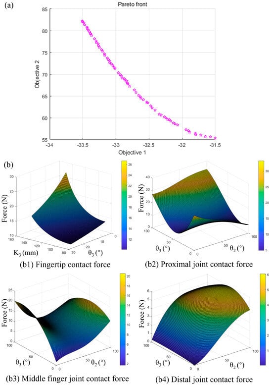
Figure 5.
The results of optimization. (a) Optimized Pareto front. (b) Variation in contact force with joint rotation angle for each knuckle.
In the multi-objective genetic algorithm, the Pareto frontier is a set of optimal solutions. In this section, when selecting the optimal design parameters, the values of the two optimization objectives obtained are summed and sorted in descending order, and then the median value is taken to reduce the error caused by a single optimization. A total of 10 runs is performed, and the average value of the 10 optimizations is selected as the final optimization result, as shown in Table 2.

Table 2.
Optimization results of linkage variables.
Substituting the rounded data from Table 2 and the initial conditions into Equation (15) yields the following contact forces for each phalanx: f1 = 12 N, f2 = 14 N, and f3 = 12 N, with a total contact force F1 = 38 N. From the calculation results, it can be concluded that the three knuckles have small differences in contact force (2 N), while their total contact force is as large as possible, which meets the optimization objectives.
4.3. Simulation and Experimental Verification of Flexible Structures
Conventional rigid–flexible coupling often relies on mechanical fastening methods such as bolts and buckles for connection. However, the mismatch in stiffness between rigid and flexible materials can easily lead to localized stress concentration, causing issues such as fracture at the coupling interface. For instance, although bonding with adhesives like epoxy resin or thermal welding offers high connection strength, once minor damage occurs at the interface, cracks tend to propagate rapidly, resulting in irreversible failure (as shown in Figure 6a). To address these challenges, this paper proposes the use of embedded flexible microstructures to achieve coupling between rigid and flexible materials. This approach leverages the elastic deformation capability of the microstructures to enhance the toughness of the rigid–flexible interface. The connection performance is thoroughly evaluated through a combination of experimental and simulation-based analyses.

Figure 6.
Rigid–flexible coupling method. (a) Bonding interface crash. (b) The principle of embedded microstructure rigid–flexible coupling. (c) Rigid–flexible coupling through embedded flexible microstructures and the simulation analysis results diagram of the embedded flexible microstructures.
4.3.1. Design and Analysis of Embedded Flexible Microstructures
Owing to the significant mismatch in elastic moduli between rigid and flexible materials, their coupling interface is prone to irreversible damage, such as delamination, slippage, and curling, under stress, as shown in Figure 6a.
To address this challenge, this paper proposes an approach to enhance the interface connection toughness in rigid–flexible coupling through the elastic deformation of embedded flexible microstructures. These microstructures are integrated with the rigid material via a unified casting process, the details of which have been described in previous sections. Figure 6b illustrates the working principle of the embedded microstructures enabling rigid–flexible coupling. Under tension, the solidified micro-cylinders undergo preferential tensile deformation, while the flexible structures embedded within the rigid matrix maintain connection strength. These micro-cylinders not only exhibit high deformability but also elastically recover to their original state upon the release of tension, thereby ensuring robust interface toughness.
In the simulation, for the convenience of modeling and to avoid the microstructure separating from the rigid structure when under tension, we simplified the geometric shape of the microstructure into a dovetail type. Figure 6c presents a schematic of the underactuated gripper achieving rigid–flexible coupling through an array of embedded microstructures, along with simulation results of their mechanical behavior. The upper light-yellow section represents the flexible part of the gripper, while the lower blue section corresponds to the 3D-printed rigid connecting plate. The two components are coupled via a periodic array of embedded flexible microstructures.
The inset in the lower right of Figure 6c displays the simulation results of the microstructures under tension. During simulation, the far end of the rigid body is displaced, and the stress distribution within the flexible microstructure is analyzed. The results indicate that tensile stress is concentrated within the elastic microstructures, which demonstrates their role in converting interfacial slip energy into deformation energy. This mechanism not only prevents damage to other components but also significantly improves the toughness of the rigid–flexible interface through elastic energy dissipation.
4.3.2. Simulation Analysis of Embedded Flexible Microstructures
To evaluate the elastic energy dissipation performance of the flexible microstructures, a series of parametric studies were carried out using the finite element software Abaqus 2024. Two key geometric parameters, the height (H) and the diameter (R) of the flexible microstructure, were investigated to assess their effects on the toughness of the interfacial coupling. The influence of these structural parameters on the connection performance was systematically analyzed.
The simulation model is established as follows: for simplicity, the flexible structure embedded within the rigid material is modeled as an isotropic cylinder with a base radius of 25 mm. This design helps prevent slippage during tension and reduces stress concentration. Within this model, the height (H) and diameter (R) of the microstructures were varied: H ranged from 10 mm to 20 mm, and R from 5 mm to 20 mm. Throughout the simulations, the values of H and R are incrementally increased, and the resulting deformation and elastic energy dissipation of the microstructure underload are recorded and analyzed.
Figure 7 presents the simulation results for varying microstructures height (H). Figure 7a compares the shear and tensile simulation outcomes across multiple values of H, which illustrates the deformation trends of the microstructure under both tensile and shear loads for a fixed diameter (R). Analysis of the results in Figure 7b shows that as H increases, both the shear and tensile dissipations increase gradually, which enhances toughness at the rigid–flexible interface. As shown in Figure 7c, although increasing H improves connection performance and allows the microstructures to withstand greater deformation, excessive height results in increased longitudinal deformation during tension. This can cause significant relative displacement between the rigid and flexible components, thereby compromising the stability of the rigid–flexible coupling structure.
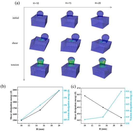
Figure 7.
The simulation results of different microstructure H sizes. (a) Influence of microstructure height H on rigid-flexible coupling connection performance. (b) Tension and shear dissipation of different microstructure H sizes. (c) Tension and shear dissipation energy of different microstructure H sizes.
Figure 8 shows the simulation analysis results of changing the R parameter of the flexible microstructure. Figure 8a presents the shear and tension simulation results for multiple groups of microstructures with different R parameters. The simulation results in Figure 8b indicate that as the R parameter of the microstructure increases, both the shear dissipation energy and tension dissipation energy gradually increase and then tend to stabilize. As shown in Figure 8c, with the increase in R, the tensile displacement decreases; however, the compressible volume of the microstructure in the tangential direction increases and the shear displacement increases. A continuous increase in R will cause significant lateral slip between the rigid and flexible components, thereby leading to the instability of the rigid–flexible coupling structure.
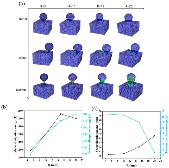
Figure 8.
The simulation results of different microstructure R sizes. (a) Influence of microstructure radius R on rigid–flexible coupling connection performance. (b) Tension and shear dissipation energy of different microstructure R sizes. (c) Tension and shear dissipation energy of different microstructure R sizes.
Increasing both the R and H parameters can improve the interfacial toughness of the flexible microstructures; however, under shear and tension actions, this increase will also enlarge the relative displacement between the rigid and flexible components, impairing the stability of the rigid–flexible coupling structure.
4.3.3. Experimental Verification of Embedded Flexible Microstructure
This section presents tensile and torsional experiments on the rigid–flexible coupling interface to evaluate the toughness of the connection achieved through embedded flexible microstructures. A 3 × 3 array of such microstructures was fabricated using an integrated casting process to form the coupling between the rigid and flexible materials. Tensile and torsional tests, the latter simulating shear conditions, were then performed to examine the deformation behavior of the microstructures and the integrity of the interface under mechanical load.
Figure 9a illustrates the tensile experiment performed on the array of microstructures. During testing, the rigid–flexible coupling structure is subjected to transverse tensile loading. As the tensile displacement increases, the flexible microstructures undergo considerable deformation. Even when stretched to 10 mm, neither the rigid nor the flexible components show signs of deformation or damage.
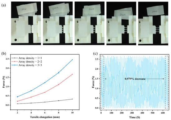
Figure 9.
Experiments on microstructures. (a) Tensile test of arrayed microstructures. (b) The force of microstructural arrays with different densities. (c) The result of fatigue experiments.
As shown in Figure 9b, we selected array microstructures with both R and H of 1.5 mm, and array densities of 1 × 1, 2 × 2, and 3 × 3. These microstructures were stretched by 2 mm, 4 mm, 6 mm, 8 mm, and 10 mm; then, we recorded the pulling force. With increasing microstructure array density, the interface becomes stronger. However, a higher array density results in excessively small microstructure diameters and overly small pore sizes of the porous plate. During the process of liquid silicone flowing into the porous plate, this small pore size leads to high flow resistance and makes fabrication difficult.
As shown in Figure 9c, we conducted tensile-recovery fatigue experiments on a 3 × 3 array of microstructures with both radius R and height H of 2 mm. The test adopted a tensile-recovery cycle of 2.5 s, a tensile length of 8 mm, and test duration of 650 s. We selected the average tensile force from the first 10 cycles and the last 10 cycles for calculation, and the results showed that the tensile force decrease was 0.979% after 650 s of cycling. This indicates that the flexible microstructure has good fatigue strength.
4.3.4. Simulation Analysis of the Expansion Behavior of Soft Actuator
To improve the compliance and safety of the rigid–flexible coupling gripper, this paper introduces a soft actuator integrated with the flexible microstructures. As shown in Figure 10a,b, the schematic diagrams illustrate how soft actuator inflation enhances the grasping performance of the gripper. Without the soft actuator, contact between the gripper and the object occurs only at discrete points. In contrast, the soft actuator not only compensates for expansion displacement while grasping but also adjusts both the contact force and the contact area between the gripping surface and the object. This helps prevent irreversible damage to delicate or fragile objects caused by excessive grasping force or stress concentration.
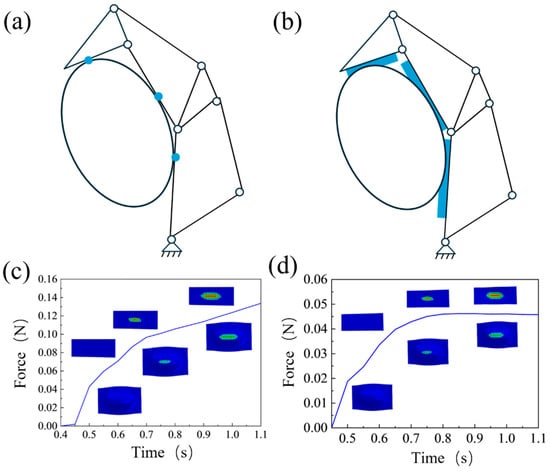
Figure 10.
The soft actuator inflation simulation. (a,b) The principle of soft actuator inflation. (c,d) Simulation analysis of expansion behavior for soft actuator.
The inflation behavior of the soft actuator is analyzed using Abaqus simulation software for grasping scenarios involving both rigid and flexible objects. The fluid cavity feature is employed to model inflation, with pressure dynamically increased from an initial value of 0 Pa to a final value of 35 kPa. The grasped objects are assigned two distinct material properties, rigid and flexible, to simulate interactions with soft, compliant items as well as fragile, breakable objects.
As shown in Figure 10a,b, when multi-jointed fingers grasp objects, their rigid contact takes the form of point contact, which easily leads to stress concentration and consequently causes damage to object surface. In contrast, flexible contact can increase the contact area, average the force distribution, and enhance stability and safety during the grasping process. The simulation results are shown in Figure 10c,d. When the input pressure is 35 kPa (as presented in Figure 10c), the upper part of the nephogram shows the stress distribution of the contacted object, including rigid Figure 10c and soft Figure 10d objects, while the lower part shows the stress distribution of the soft actuator.
It can be seen from the simulation results that the maximum contact force exerted by the soft actuator on the rigid object is approximately 0.16 N, and this force continues to increase, helping to provide sufficient grasping force for stable object grasping. For grasping flexible objects (as shown in Figure 10d), as the object approaches, the contact area between the finger and the flexible object increases rapidly, and the contact force first increases and then stabilizes, with a maximum value of only 0.06 N. The larger contact area enhances grasping stability and significantly reduces stress concentration during the process.
The simulation results confirm that the inflation of the soft actuator provides a reliable safety guarantee for the object being grasped during the grasping process.
4.4. Grasping Experiments of the Rigid–Flexible Coupling Gripper
This section presents a series of grasping experiments conducted on the underactuated rigid–flexible coupling gripper to evaluate its grasping adaptability. As shown in Figure 11a, a three-dimensional motion platform is constructed for the tests. Stepper motors are used to control translational motion along the X, Y, and Z axes. A prototype of the underactuated rigid–flexible coupling gripper is mounted at the end of the Z-axis slide, and its grasping motion is regulated by an onboard drive motor.
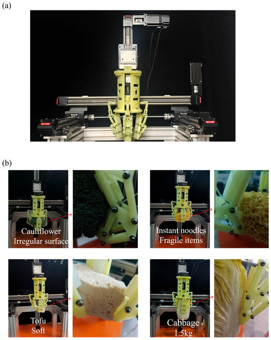
Figure 11.
The grasping experiment. (a) Construction of the three-dimensional motion platform. (b) The detail of the grasping experiment.
To evaluate the adaptive enveloping grasping capability of the proposed gripper, we select objects with variations in size, mass, shape, and material stiffness for testing. In addition, a video of the experiment is captured using a camera. Table 3 provides the detailed parameters of the objects used in the grasping experiments.

Table 3.
Grasping object parameter.
The detailed grasping results are shown in Figure 11b. The surface of the cauliflower is highly irregular. During grasping, the multi-joint underactuated fingers not only achieve adaptive enveloping grasps, but the soft actuator structure also conforms tightly to the uneven surface without causing damage, demonstrating high compliance and stability.
Instant noodles are fragile and easily broken, placing high demands on the grasping force control of the gripper. Through the synergy of rigid and flexible components, the proposed underactuated rigid–flexible coupling gripper achieves non-destructive grasping of the noodle surface, exhibiting excellent performance. After structural optimization, the rigid underactuated mechanism ensures a uniform contact force across all joints during enveloping, thereby avoiding breakage caused by excessive local pressure, while the flexible structure further ensures compliant contact. In addition, the inflation of the soft actuator during grasping increases the contact area, reduces stress concentration, and enhances interaction stability and safety.
Video S1 of the Supporting Information shows the experimental process of grasping tofu with a rigid–flexible coupling gripper. Tofu has a soft texture and a relatively significant weight for its size due to its water content. Similarly, Video S2 shows the experiment of grabbing a cake. The combined action of the underactuated mechanism and the soft actuator prevent damage during grasping, while the rigid structure provides grasp stability. Video S3 shows the experimental process of grasping an irregular stone. The soft actuator structure can fit well with the irregular surfaces of stones, enabling stable grasping. For heavier fruits and vegetables, the rigid underactuated linkage ensures a stable grasp while the soft actuator protects the surface. Together, they enable the non-destructive grasping of 1500 g cabbage. The gripper is centered at its base with a radius of 55 mm. On the horizontal plane, its maximum extension radius is 150 mm, maximum expansion angle is 150 degrees, and minimum contraction radius is 5 mm. In the envelope posture, it can maximally envelope a sphere with a radius of 50 mm.
The experiments demonstrate that the proposed rigid–flexible coupling gripper can adjust its grasping strategy according to object characteristics such as size, shape, weight, and stiffness. While enveloping grasps, the underactuated rigid structure exhibits strong contour adaptability and high load-bearing capacity. The soft actuator further compensates for displacement through its deformation, regulates grasping force, and optimizes the contact interface, significantly improving the versatility, safety, and reliability of the gripper. It is suitable for unstructured environments, precision tasks, and human–robot collaboration. The proposed design shows great application potential in fields such as fruit and vegetable picking, as well as the handling of general goods, daily necessities, and fragile items, which greatly expands the application scope and accelerates the industrial adoption of soft grippers.
5. Conclusions
In summary, this paper proposes a rigid–flexible coupling gripper with high grasping adaptability. The rigid underactuated structure, optimized in size, exhibits a gripping force variation in only 2 N between finger knuckles, enabling both stable and adaptive grasping. After integration with the soft actuator, the contact area during interaction is increased, enhancing conformity with the object and resulting in a smoother gripping process. The rigid and flexible materials are coupled via flexible microstructures. Under tension of 10 mm or a 90° shear force at the interface, the structure elastically recovers. Even if a single microstructure is damaged, the remaining structures maintain interface integrity, significantly improving the connection toughness between rigid and flexible materials. In grasping experiments, the system demonstrated the ability to stably and safely grasp objects of various shapes, including brittle, soft, large, and heavy items. These results confirm that the rigid–flexible coupling gripper possesses sufficient load capacity for stable grasping while ensuring compliant and safe interaction, markedly improving its adaptability to diverse objects.
Supplementary Materials
The following supporting information can be downloaded at: https://www.mdpi.com/article/10.3390/act14110529/s1, Video S1: The process of the gripper picking up tofu; Video S2: The process of the gripper picking up cake; Video S3: The process of the gripper picking up irregular Stone.
Author Contributions
Conceptualization, Y.W.; Methodology, Y.W.; Software, X.H. (Xuejia Huang), B.G., Z.W., Y.C., X.H. (Xueqi Hu) and R.D.; Validation, Y.W.; Investigation, Y.H.; Resources, Y.W.; Data curation, X.H. (Xuejia Huang); Writing—original draft, X.H. (Xuejia Huang); Writing—review & editing, X.H. (Xuejia Huang); Visualization, Y.H.; Supervision, Y.W.; Project administration, Y.W.; Funding acquisition, Y.W. All authors have read and agreed to the published version of the manuscript.
Funding
This work was supported by the Natural Science Foundation project of Jiangxi Province (Grant No. 20242BAB20207) and National Natural Science Foundation of China (Grant No. 52405615).
Data Availability Statement
The original contributions presented in this study are included in the article/Supplementary Materials. Further inquiries can be directed to the corresponding author.
Conflicts of Interest
The authors declare no conflicts of interest.
References
- Gu, G.; Zhang, N.; Xu, H.; Lin, S.; Yu, Y.; Chai, G.; Ge, L.; Yang, H.; Shao, Q.; Sheng, X.; et al. A soft neuroprosthetic hand providing simultaneous myoelectric control and tactile feedback. Nat. Biomed. Eng. 2021, 7, 589–598. [Google Scholar] [CrossRef]
- AboZaid, Y.A.; Aboelrayat, M.T.; Fahim, I.S.; Radwan, A.G. Soft robotic grippers: A review on technologies, materials, and applications. Sens. Actuators A Phys. 2024, 372, 115380. [Google Scholar] [CrossRef]
- Tawk, C.; Alici, G. A review of 3D-printable soft pneumatic actuators and sensors: Research challenges and opportunities. Adv. Intell. Syst. 2021, 3, 2000223. [Google Scholar] [CrossRef]
- Cianchetti, M.; Laschi, C.; Menciassi, A.; Dario, P. Biomedical applications of soft robotics. Nat. Rev. Mater. 2018, 3, 143–153. [Google Scholar] [CrossRef]
- Wu, Z.P.; Li, X.N.; Guo, Z.H. A novel pneumatic soft gripper with a jointed endoskeleton structure. Chin. J. Mech. Eng. 2019, 32, 95–106. [Google Scholar] [CrossRef]
- Laschi, C.; Mazzolai, B.; Cianchetti, M. Soft robotics: Technologies and systems pushing the boundaries of robot abilities. Sci. Robot. 2016, 1, eaah3690. [Google Scholar] [CrossRef] [PubMed]
- Rus, D.; Tolley, M.T. Design, fabrication and control of soft robots. Nature 2015, 521, 467–475. [Google Scholar] [CrossRef] [PubMed]
- Lee, C.; Kim, M.; Kim, Y.J.; Hong, N.; Ryu, S.; Kim, H.J.; Kim, S. Soft robot review. Int. J. Control Autom. Syst. 2017, 15, 3–15. [Google Scholar] [CrossRef]
- Fu, H.-C.; Ho, J.D.; Lee, K.-H.; Hu, Y.C.; Au, S.K.; Cho, K.-J.; Sze, K.Y.; Kwok, K.-W. Interfacing soft and hard: A spring reinforced actuator. Soft Robot. 2020, 7, 44–58. [Google Scholar] [CrossRef]
- Su, J.; Tan, J.M.R.; Liu, J.; He, K.; Wu, D.; Lai, W.; Cao, J.; Phee, S.J.; Magdassi, S.; Chen, X. Bioarchitectonics-inspired soft grippers with cutaneous slip perception. Sci. Adv. 2025, 11, eadx4206. [Google Scholar] [CrossRef]
- Hu, Q.Q.; Huang, H.J.; Dong, E.B.; Sun, D. A bioinspired composite finger with self-locking joints. IEEE Robot. Autom. Lett. 2021, 6, 1391–1398. [Google Scholar] [CrossRef]
- Shen, Z.; Zhong, H.; Xu, E.; Zhang, R.; Yip, K.C.; Chan, L.L.; Chan, L.L.; Pan, J.; Wang, W.; Wang, Z. An Underwater Robotic Manipulator with Soft Bladders and Compact Depth-Independent Actuation. Soft Robot. 2020, 7, 535–549. [Google Scholar] [CrossRef] [PubMed]
- Wang, D.M.; Xiong, Y.; Zi, B.; Qian, S.; Wang, Z.Y.; Zhu, W.D. Design, analysis and experiment of a passively adaptive underactuated robotic hand with linkage-slider and rack pinion mechanisms. Mech. Mach. Theory 2021, 155, 104092. [Google Scholar] [CrossRef]
- Deimel, R.; Brock, O. A novel type of compliant and underactuated robotic hand for dexterous grasping. Int. J. Robot. Res. 2016, 35, 161–185. [Google Scholar] [CrossRef]
- Zhang, Y.; Zhang, W.; Yang, J.; Pu, W. Bioinspired soft robotic fingers with sequential motion based on tendon-driven mechanisms. Soft Robot. 2022, 9, 531–541. [Google Scholar] [CrossRef] [PubMed]
- Wu, T.; Liu, Z.; Ma, Z.; Wang, B.; Ma, D.; Yu, H. Bionic soft robotic gripper with feedback control for adaptive grasping and capturing applications. Front. Mech. Eng. 2024, 19, 8. [Google Scholar] [CrossRef]
- Zhu, J.; Chen, H.; Chai, Z.; Ding, H.; Wu, Z. A Dual-Modal Hybrid Gripper with Wide Tunable Contact Stiffness Range and High Compliance for Adaptive and Wide-Range Grasping Objects with Diverse Fragilities. Soft Robot. 2024, 11, 371–381. [Google Scholar] [CrossRef]
- Gosselin, C.M. Adaptive Robotic mechanical systems: A design paradigm. J. Mech. Des. 2006, 128, 192–198. [Google Scholar] [CrossRef]
- Sun, L.L.; Zhang, H.O.; Lin, H.; Pan, W.J. Design and research of an underactuated manipulator based on the metamorphic mechanism. Sensors 2022, 22, 4766. [Google Scholar] [CrossRef]
- Abondance, S.; Teeple, C.B.; Wood, R.J. A dexterous soft robotic hand for delicate in-hand manipulation. IEEE Robot. Autom. Lett. 2020, 5, 5502–5509. [Google Scholar] [CrossRef]
- Wei, Y.; Chen, Y.; Ren, T.; Chen, Q.; Yan, C.; Yang, Y.; Li, Y. A novel variable stiffness robotic gripper based on integrated soft actuating and particle jamming. Soft Robot. 2016, 3, 134–143. [Google Scholar] [CrossRef]
- Wang, H.; Abu-Dakka, F.J.; Le, T.N.; Kyrki, V.; Xu, H. A novel soft robotic hand design with human-inspired soft palm: Achieving a great diversity of grasps. IEEE Robot. Autom. Mag. 2021, 28, 37–49. [Google Scholar] [CrossRef]
- Ge, Q.; Sakhaei, A.H.; Lee, H.; Dunn, C.K.; Fang, N.X.; Dunn, M.L. Multimaterial 4D printing with tailorable shape memory polymers. Sci. Rep. 2016, 6, 31110. [Google Scholar] [CrossRef] [PubMed]
- Zhou, J.; Shu, C.; Zheng, W. A soft-robotic gripper with enhanced object adaptation and grasping reliability. IEEE Robot. Autom. Lett. 2017, 2, 2287–2293. [Google Scholar] [CrossRef]
- Xie, Z.; Domel, A.G.; An, N.; Green, C.; Gong, Z.; Wang, T.; Knubben, E.M.; Weaver, J.C.; Bertoldi, K.; Wen, L. Octopus arm-inspired tapered soft actuators with suckers for improved grasping. Soft Robot. 2020, 7, 639–648. [Google Scholar] [CrossRef]
- Chen, H.; Zhu, J.; Cao, Y.; Xia, Z.; Chai, Z.; Ding, H.; Wu, Z. Soft-rigid coupling grippers: Collaboration strategies and integrated fabrication methods. Sci. China Technol. Sci. 2023, 66, 3051–3069. [Google Scholar] [CrossRef]
- Su, C.; Wang, R.; Lu, T.; Wang, S. SAU-RFC hand: A novel self-adaptive underactuated robot hand with rigid-flexible coupling fingers. Robotica 2022, 41, 511–529. [Google Scholar] [CrossRef]
- Tang, Y.C.; Chi, Y.D.; Sun, J.F.; Huang, T.H.; Maghsoudi, O.H.; Spence, A.; Zhao, J.; Su, H.; Yin, J. Leveraging elastic instabilities for amplified performance: Spine-inspired high-speed and high-force soft robots. Sci. Adv. 2020, 6, eaaz6912. [Google Scholar] [CrossRef]
- Liu, C.H.; Chuang, F.M.; Chen, Y.; Chiu, C.H.; Chen, T.L. Optimal design of a motor-driven three-finger soft robotic gripper. IEEE/ASME Trans. Mechatron. 2020, 25, 1830–1840. [Google Scholar] [CrossRef]
- Guo, X.Y.; Li, W.B.; Gao, Q.H.; Yan, H.; Fei, Y.Q.; Zhang, W.M. Self-locking mechanism for variable stiffness rigid-soft gripper. Smart Mater. Struct. 2020, 29, 35033. [Google Scholar] [CrossRef]
- Zhu, J.; Chai, Z.; Yong, H.; Xu, Y.; Guo, C.; Ding, H.; Wu, Z. Bioinspired Multimodal Multipose Hybrid Fingers for Wide-Range Force, Compliant, and Stable Grasping. Soft Robot. 2023, 10, 30–39. [Google Scholar] [CrossRef]
Disclaimer/Publisher’s Note: The statements, opinions and data contained in all publications are solely those of the individual author(s) and contributor(s) and not of MDPI and/or the editor(s). MDPI and/or the editor(s) disclaim responsibility for any injury to people or property resulting from any ideas, methods, instructions or products referred to in the content. |
© 2025 by the authors. Licensee MDPI, Basel, Switzerland. This article is an open access article distributed under the terms and conditions of the Creative Commons Attribution (CC BY) license (https://creativecommons.org/licenses/by/4.0/).