Article

Application of Adaptive Discrete Feedforward Controller in Multi-Axial Real-Time Hybrid Simulation

1
Department of Civil and Mineral Engineering, University of Toronto, Toronto, ON M5S 1A4, Canada
2
School of Civil Engineering, Chang’an University, Xi’an 710061, China
*
Author to whom correspondence should be addressed.
Actuators 2025, 14(11), 525; https://doi.org/10.3390/act14110525 (registering DOI)
Submission received: 20 August 2025 / Revised: 19 October 2025 / Accepted: 27 October 2025 / Published: 29 October 2025
(This article belongs to the Special Issue Analysis and Design of Linear/Nonlinear Control System)

Abstract

Real-time hybrid simulation (RTHS) evaluates the dynamic performance of a structure by physically testing the selected components while modeling the remaining structure numerically, making it efficient in both cost and testing space requirements. In RTHS, accurately imposing target boundary conditions on specimens is critical, as it directly influences test accuracy and overall simulation stability. However, boundary condition application often experiences tracking errors due to the dynamics of the servo–hydraulic loading system and control-structural interaction. This challenge intensifies with multiple actuators operating in a multi-axial setup, introducing dynamic coupling effects. Thus, an outer-loop controller enabling precise actuator tracking of reference boundary conditions is essential for reliable RTHS. While advancements in outer-loop controllers for uniaxial RTHS exist, multi-axial RTHS (maRTHS) employing multiple degrees of freedom control remains underexplored. This study applies the adaptive discrete feedforward controller (ADFC), consisting of a discrete feedforward compensator and an online identifier, to a multi-input, multi-output (MIMO) system for maRTHS. To validate ADFC’s performance and robustness, 1000 virtual maRTHS tests incorporating plant uncertainties were conducted under seismic excitations. Ten evaluation criteria were applied. Results confirm that ADFC achieves robust and stable control by reducing phase and amplitude errors, while also improving estimation accuracy at the physical–numerical interface.

1. Introduction

Real-time hybrid simulation (RTHS) is a cyber–physical testing technique used to evaluate the performance of structural systems under controlled dynamic loading conditions. In RTHS, a portion of the structure undergoes physical testing (the experimental substructure), while the remaining part is numerically modeled (the numerical substructure) [1,2]. RTHS is considered a cost-effective alternative to shaking table testing [3] for effectively evaluating the seismic performance of structures equipped with vibration absorbers, which are typically rate-dependent, and has been widely utilized in numerous studies [4]. However, compared to shaking table testing, implementing RTHS presents more challenges, particularly in accurately enforcing realistic boundary conditions on the experimental substructure [5]. Due to the inherent dynamics of the actuators [6] and control–structure interaction [7], tracking errors arise between the target and measured displacements during the trajectory tracking of the actuators. These errors not only deteriorate test accuracy but can also destabilize the system, necessitating robust outer-loop controllers that mitigate interface desynchronization.
To address these issues, researchers focused on time delay compensation, such as polynomial extrapolation [8,9,10], phase-lead compensation [11,12], and inverse compensation [13,14], which assume constant delay and fixed plant dynamics. However, because RTHS systems often exhibit time-varying characteristics, these methods are limited in handling the full spectrum of uncertainties [15].
Adaptive compensation approaches, which adjust control parameters dynamically in response to time-varying system behavior in real time, offer a more robust solution. Parameter estimation-based adaptive controllers predominantly utilize Kalman filtering variants and least squares (LS) methods. Chae et al. [16] introduced an adaptive time series (ATS) compensator, using LS estimation to update system parameters in real time. Palacio-Betancur and Gutierrez Soto [17] further improved this strategy by applying recursive least squares (RLS) estimation. Similar approaches have incorporated Kalman filtering for online parameter identification, with Ning et al. [18] applying conventional Kalman filters, while later studies explored advanced nonlinear estimators such as the extended Kalman filter (EKF) and unscented Kalman filter (UKF). These methods have demonstrated effectiveness in capturing actuator dynamics under uncertainty and nonlinearity [19,20,21]. Model-based adaptive controllers combine feedforward compensation with parameter estimation. Wang et al. [22] proposed a two-stage adaptive delay compensation method combined with an adaptive Kalman noise filter, achieving strong tracking performance. Ning et al. [23] enhanced feedforward compensation by incorporating feedback control to reduce reliance on discrete actuator dynamics modeling, validating the proposed method through both virtual and physical RTHS platforms. Similarly, Wang et al. [24] employed an adaptive delay compensation scheme based on discrete system modeling, allowing real-time updates that reflect actuator dynamics variability. Learning-based adaptive controllers have also emerged, including neural network-based approaches [25,26], deep reinforcement learning [27], and data-driven nonlinear autoregressive with exogenous (NARX) input models that learn system behavior patterns during operation [28].
However, most of these adaptive control schemes have been developed for single-input, single-output (SISO) systems and cannot directly be implemented to multi-input, multi-output (MIMO) configurations due to cross-coupling effects between actuators [29]. As testbeds evolved to include MIMO interfaces, controlling the boundary condition application became increasingly complex. Researchers began exploring multi-axial configurations that could replicate the spatial dynamics of large-scale structures. Early efforts by Chen et al. [30] demonstrated multi-directional hybrid testing of piping systems. Nakata et al. [29] developed the Load and Boundary Condition Box (LBCB), a six-actuator, self-reaction loading system featuring Cartesian calibration and mixed load/displacement control, validated through multi-dimensional hybrid simulations on a skew reinforced concrete bridge. Mercan et al. [31] further formalized this concept through a kinematic transformation method that mapped global structural DOFs to local actuator displacements, preserving compatibility at multi-point interfaces. Subsequent systems, such as the Multi-Axial Sub-assemblage Testing (MAST) facility described by Al-Mahaidi et al. [32] and the 6-DOF hybrid frame model developed by Hashemi et al. [33], expanded these capabilities by enabling robust actuator coordination and collapse-level testing of reinforced concrete frames under coupled translational and rotational loading. Together, these multi-axial testing platforms established the hardware foundation for maRTHS and demonstrated the feasibility of accurate three-dimensional (3D) boundary control. Gao et al. [1] proposed a generalized robust control procedure for MDOF RTHS. Phillips et al. [34] introduced a coupled MIMO control architecture for RTHS that captured actuator interactions and system-wide dynamics, while Fermandois and Spencer [35] developed a model-based framework control method tailored to multi-axial simulation. Najafi et al. [36] and Najafi and Spencer [37] introduced a multi-actuator RTHS framework capable of decoupling control for six actuators, validated on small-scale experiments with potential for full-scale extension. Tian et al. [38] proposed an enhanced three-variable control method to track high-frequency force signals in MDOF boundary coordination setups.
In parallel, extensive progress in multi-axial hybrid simulation (maHS) under quasi-static or slow-dynamic conditions advanced actuator coordination and kinematic calibration, as demonstrated by Elnashai et al. [39], Høgh et al. [40], Tsokanas et al. [41], and Huang et al. [42]. Additional experimental infrastructures such as the Large Universal Shell Element Tester (LUSET) [43], the UT10 Simulator [44], large-scale hybrid testing facilities at E-Defense [45], Network for Earthquake Engineering Simulation (NEES) [46], and Natural Hazards Engineering Research Infrastructure (NHERI) [47] expanded the applicability of these systems to geographically distributed and full-scale configurations.
Reflecting the growing interest in multi-axial RTHS, the benchmark problem introduced by Condori et al. [48] provides an openly available virtual testbed with coupled translational and rotational DOFs, fostering the comparative evaluation of control algorithms. Utilizing this virtual multi-axial RTHS (v-maRTHS) benchmark problem, Ruiz and Song [49] implemented EKF and UKF estimators in both transfer function (TF) and state–space (SS) formats for MIMO RTHS, demonstrating that UKF-SS provided the most robust tracking under measurement noise and uncertainty. Aguila et al. [50] developed conditional adaptive time series (CATS) compensation, coupling it with proportional–integral–derivative (PID) control and model predictive control (MPC). Their comprehensive study demonstrated that CATS-enabled controllers maintain stability and precision across complex multi-axial boundary conditions. Shangguan et al. [51] and Quiroz et al. [52] further advanced adaptive delay compensation using sliding-mode and robust decentralized adaptive controllers, respectively.
Recent advances in RTHS have placed increasing emphasis on addressing the inherent limitations of servo–hydraulic actuators, particularly their inability to track command signals under high-speed and multi-axial loading scenarios. To mitigate these tracking errors, characterized by phase lead/lag, amplitude overshoot/undershoot, Tao and Mercan [53] introduced the adaptive discrete feedforward controller (ADFC), a model-based discrete feedforward compensator that adapts online to minimize actuator tracking errors in SISO-RTHS applications [54,55]. Unlike traditional offline system identification approaches, the ADFC leverages a finite impulse response (FIR) structure, continuously updated through least squares estimation using recent actuator error history. This strategy effectively compensates for time-varying system dynamics and modeling uncertainties while preserving stability. Its data-driven structure, low computational cost, and stability make it especially suitable for maRTHS applications where precise actuator motion is critical for maintaining RTHS fidelity.
In this study, the ADFC, a data-driven feedforward compensator originally developed and tested for single-actuator RTHS, is extended to a decentralized multi-actuator framework within a hybrid model-based/data-driven RTHS architecture using the v-maRTHS benchmark. In the proposed approach, the model-based Kalman estimator governs system states, while each actuator independently adapts its feedforward law through online least-squares identification over a shared regressor that implicitly captures cross-coupling, thereby enhancing actuator tracking and interface synchronization under seismic excitations without requiring an explicit coupled plant model. The proposed implementation is tested against a reference linear quadratic Gaussian (LQG) controller across 1000 random simulations under three ground motion inputs, evaluating both tracking accuracy and global system response estimation. Through this investigation, the study aims to demonstrate the potential of ADFC to deliver robust, high-fidelity performance in multi-DOF hybrid simulations, and to lay the groundwork for future real-time experimental validation.

2. Materials and Methods

2.1. Properties of the Reference Structure

The maRTHS benchmark problem introduced by Condori et al. [48] provides a virtual testbed designed to evaluate the performance of control algorithms in a multi-actuator setting. This benchmark problem increases complexity compared to the uniaxial RTHS benchmark problem developed by Silva et al. [56], by including two actuators controlling displacement and rotation at the boundary between numerical and experimental substructures. This facilitates the development and validation of advanced control strategies, particularly for MIMO systems, and aims to simulate realistic boundary conditions, actuator coupling, and nonlinear dynamics.
Figure 1 presents the configuration and geometric details of the reference structure employed in the maRTHS benchmark problem. The structure is a three-story, three-bay moment-resisting steel frame designed to represent a laboratory-scale testbed for dynamic structural experiments. All columns in the structure are standard W5 × 16 rolled steel sections, providing uniform vertical stiffness across the height. The beams, however, are custom-fabricated built-up sections, labeled as BU-1 and BU-2. These beams are welded I-sections made from flat steel plates. A uniform vertical distributed load of 49.03 N/mm is applied on all BU-2 beams, simulating sustained gravity loads. The exterior columns are fixed to the foundation, whereas the interior columns are connected using S3 × 5.7 rolled sections, which act as simple supports. The structure’s first five natural frequencies and corresponding modal mass participation ratios are given in Table 1.
Figure 2 shows the degree-of-freedom (DOF) description, together with structural partitioning and interface configuration used in the maRTHS benchmark problem. The reference frame includes a total of 16 nodes. Nodes 1 to 12 correspond to beam-to-column joints across the three levels, while nodes 13 to 16 represent base support locations. This configuration allows each node to possess three DOFs: horizontal translation (x), vertical translation (y), and in-plane rotation (θ). The model comprises a total of 38 DOFs, which are organized within the displacement vector, ψ = ψ 1 , , ψ 38 T . The central bay, indicated in red, serves as the experimental substructure and was physically tested in the laboratory [5,56,57]. This region is connected to the numerical substructure, comprising the two outer bays, through interface nodes labeled 4 and 7. These nodes are assigned six degrees of freedom in total, enabling the actuators to enforce multi-directional motion during testing.
Figure 2b illustrates how displacement commands are transferred from the numerical model to the experimental substructure and how restoring forces are fed back into the numerical substructure. The displacement vectors computed by the numerical model, denoted as ψ n s 4 and ψ n s 7 , are imposed at the interface by the actuators, which physically move the experimental frame accordingly. In turn, the measured reaction forces and moments, f e s 4 and f e s 7 , are transmitted back to the numerical model to complete the hybrid simulation loop. This bidirectional exchange of displacement and force enables a realistic representation of structural behavior, where the interaction between the numerical and physical domains is governed by real-time communication.
The maRTHS study focuses solely on seismic excitation in the planar horizontal direction. The equation of motion (EOM) is given by
M ψ ¨ + C ψ ˙ + K ψ = M Γ x ¨ g
where M, C, and K denote the mass, damping, and stiffness matrices of the reference structure, respectively. The vector Γ represents how the seismic input influences the system’s masses, with entries set to one in the horizontal direction, and zero elsewhere. x ¨ g is the ground acceleration function in the x-direction. Finally, ψ ¨ , ψ ˙ , and ψ correspond to the relative acceleration, velocity, and displacement of each DOF with respect to the ground. Initial rest conditions are considered for this linear–time-invariant (LTI) system (i.e., ψ i ( 0 ) = ψ ˙ i ( 0 ) = 0 , where i = [ 1 , , 38 ] ). The damping matrix is formulated using Rayleigh damping approach, where a 5% critical damping ratio is assigned to the first and third vibration modes.

2.2. Sub-Structured System Dynamics

The maRTHS benchmark problem adopts a domain decomposition strategy, wherein the full structure is divided into two subdomains: the numerical substructure (N) and the experimental substructure (E). Assuming linear elastic behavior for the entire system, the governing EOM can be partitioned accordingly. The global mass (M), stiffness (K), and damping (C) matrices are expressed as the sum of their numerical and experimental components as
M = M N + M E , K = K N + K E , C = C N + C E .
The complete EOM becomes
M N + M E ψ ¨ + C N + C E ψ ˙ + K N + K E ψ = M Γ x ¨ g .
To facilitate hybrid simulation, the contribution of the experimental substructure is shifted to the right-hand side of the EOM and grouped into a feedback force term:
M N ψ ¨ + C N ψ ˙ + K N ψ = M Γ x ¨ g f E
where
f E = M E ψ ¨ + C E ψ ˙ + K E ψ
which represents the restoring force returned by the experimental substructure and is calculated virtually in real-time during the simulation.
For the hybrid simulation to be valid, two interface conditions must be maintained. First, compatibility: the interface DOFs at the boundary between the numerical and experimental domains must have matching displacements and velocities. This ensures that the numerical substructure can command the appropriate interface motion. As shown in Figure 2, the interface DOFs include translations and rotations at nodes 4, 7, 16, 19, 28, and 31:
ψ N = ψ 4 N , ψ 7 N , ψ 16 N , ψ 19 N , ψ 28 N , ψ 31 N T .
Second, equilibrium: the internal forces from the numerical model must be balanced by the restoring forces generated by the experimental substructure. Thus, during simulation, the response forces:
f E = F 4 E , F 7 E , F 16 E , F 19 E , M 28 E , M 31 E T
are measured and sent back to the numerical model in real time. The time integration of the EOM is performed using the fixed-step Runge–Kutta integration algorithm implemented in MATLAB R2024b and Simulink R2024b [58], operating at a sampling frequency of 1024 Hz.
While Figure 2 presents an idealized maRTHS implementation, experimental testing involves additional factors such as actuator dynamics, signal noise, and structural interaction with loading equipment. These complexities can affect the dynamic behavior of the experimental domain and must be mitigated through control strategies. To simulate these effects in a computational environment, a virtual maRTHS framework is introduced.

2.3. Transfer System

The transfer system is used to simultaneously impose both lateral displacement and rotation to the experimental substructure in the maRTHS benchmark problem. The system consists of a pair of servo–hydraulic actuators configured to impose translational and rotational motions at node 4. Vertical DOF (ψ16) in the global y-direction is excluded from the analysis, as its magnitude is negligible compared to horizontal displacements. This simplification is justified by the high axial stiffness of the columns and the absence of gravity loading on the BU-1 beam of the experimental substructure, which leads to minimal axial deformation.
Due to experimental constraints, boundary conditions are only applied at node 4. The actuation is delivered through a custom-designed coupler system, allowing the two hydraulic actuators to simultaneously deliver both lateral displacement and rotation at that node. Additionally, while the DOFs of node 7 would be measured in a physical experiment, they are numerically estimated in the virtual maRTHS implementation based on idealized properties of the experimental substructure and the reconstructed motion at node 4. The integration of the transfer system modifies the experimental substructure’s dynamics, necessitating a control strategy to address these changes and related effects, which are modeled in the benchmark setup by simulating them with models identified using the experimental data [48].

2.3.1. Coordinate Transformation for the Coupler

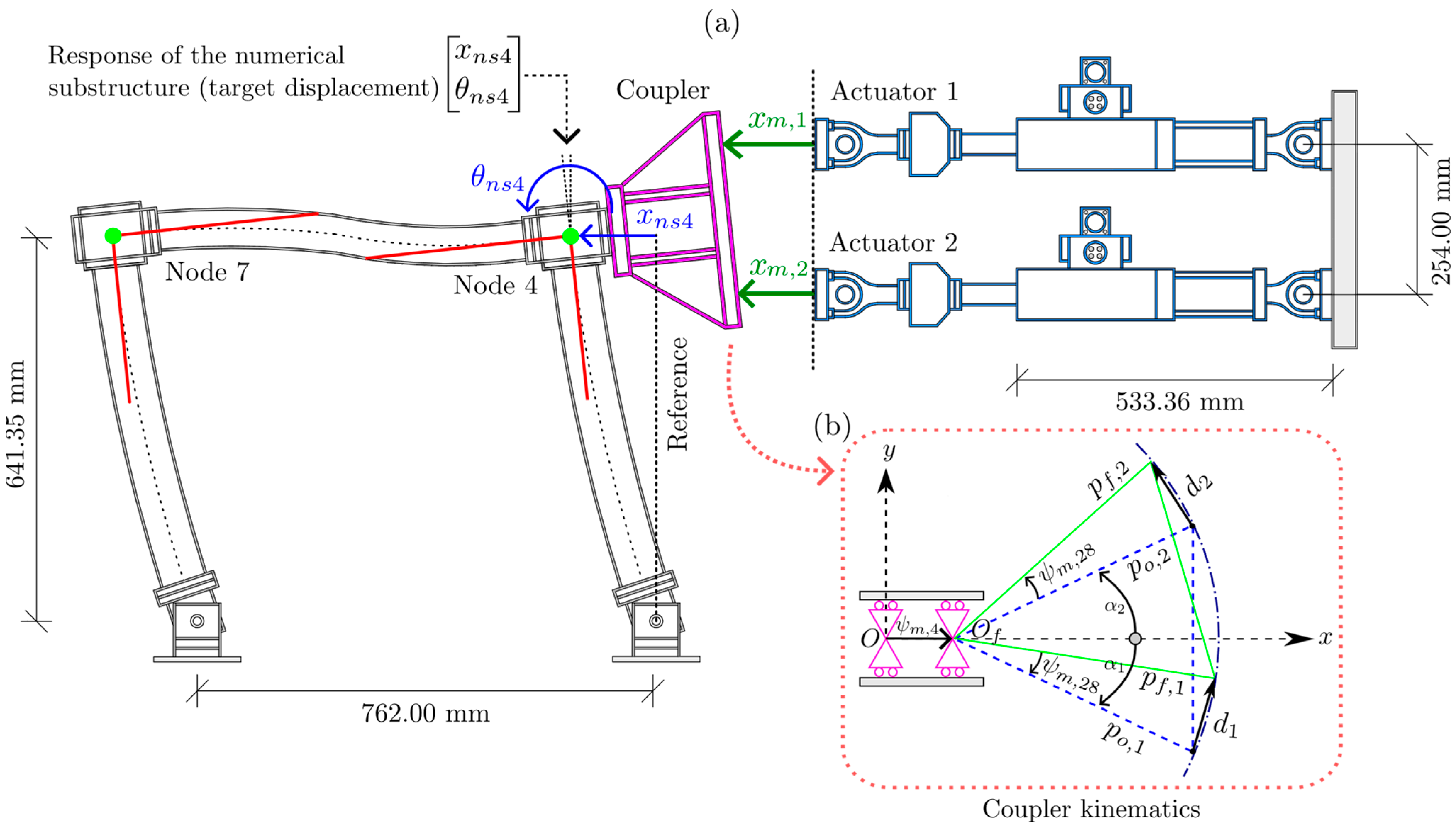
In the maRTHS benchmark setup, a pair of servo–hydraulic actuators impose motion on the experimental substructure through a rigid coupler attached to node 4 as shown in Figure 3a. Since the actuators operate in their own local coordinate system, a transformation is necessary to map the actuator displacements to the translational and rotational DOFs of node 4 in the global frame of the structure.
This transformation is based on several simplifying assumptions. The coupler is treated as a rigid body; thus, its deformation is neglected. Vertical displacements at the coupling node are ignored due to their small magnitude. The frame’s linear elastic behavior also justifies neglecting rotational flexibility at beam-column joints. Furthermore, the coupler’s connection to the specimen is considered rigid due to the use of high-strength bolts.
Figure 3b shows the triangular geometry of the rigid coupler system and its kinematic behavior. The blue dashed lines represent the initial configuration, while the green triangle depicts the deflected state due to actuator-induced motion. The total axial displacement in each actuator results from the combination of the coupler’s horizontal translation ψ m , 4 , and the horizontal components of the vectors d 1 and d 2 , which change as the coupler undergoes rotation by an angle ψ m , 28 . Considering only the rotational contribution, each actuator’s initial position is given by p o , i , and the final position by p f , i = p o , i + d i . Assuming the actuator’s displacement is primarily governed by horizontal motion, this magnitude for each actuator can be approximated as
x m , i = ψ m , 4 + p · c o s α i + ψ m , 28 c o s α i , i = 1 , 2
where p = p o , i = p f , i , under the assumption that the coupler behaves as a rigid body. The inverse relation for calculating the rotation angle ψ m , 28 from actuator displacements is
ψ m , 28 = s i n 1 x m , 1 x m , 2 2 p   s i n α 2
and the displacement at node 4 ( ψ m , 4 ) can be determined by
ψ m , 4 = x m , i p · c o s α i + ψ m , 28 c o s α i .

2.3.2. Control Plant Model Properties

In the maRTHS benchmark setup, the control plant refers to the combined dynamics of the actuator system and the experimental substructure. It is modeled as a 2 × 2 transfer matrix, since the system has two command inputs x a , 1 , x a , 2 T and two measured displacement outputs x m , 1 ,   x m , 2 T . This results in a compact matrix form of the plant as
H = H 11 H 12 H 21 H 22 .
Each transfer function H i j characterizes the response at output i   due to input j . The diagonal terms, H 11 and H 22 , represent the direct input–output relationship for each actuator. The off-diagonal terms, H 12 and H 21 , reflect internal coupling between the two actuators caused by structural interaction within the specimen.
The transfer functions are expressed as rational functions of the Laplace variable s as
G = n u m 11 ( s ) d e n 11 ( s ) n u m 12 ( s ) d e n 12 ( s ) n u m 21 ( s ) d e n 21 ( s ) n u m 22 ( s ) d e n 22 ( s ) · n u m e s ( s ) d e n e s ( s )
where n u m i j ( s ) d e n i j ( s ) defines the numerator and denominator of the transfer function H i j , and n u m e s ( s ) d e n e s ( s ) represents the corresponding poles and zeros of the experimental substructure.
The nominal values of these transfer function parameters were identified by Condori et al. [48] using experimental frequency response data, where band-limited white noise (BLWN) signals were applied to each actuator across a frequency range of 0–100 Hz. This method allows isolating the dynamic behavior of each actuator and capturing the inherent coupling within the frame. Table 2 presents the identified parameter uncertainties for the frequency response functions (FRFs) of the nominal plant models used in the maRTHS benchmark study. The transfer functions are expressed in terms of their poles and zeros. Each component is associated with a nominal value and a standard deviation for each parameter.
To account for modeling uncertainties attributed to model imprecision, the identified poles and zeros are treated as random variables with normal distributions. The propagation of these uncertainties is captured by generating a family of transfer functions using Monte Carlo sampling.
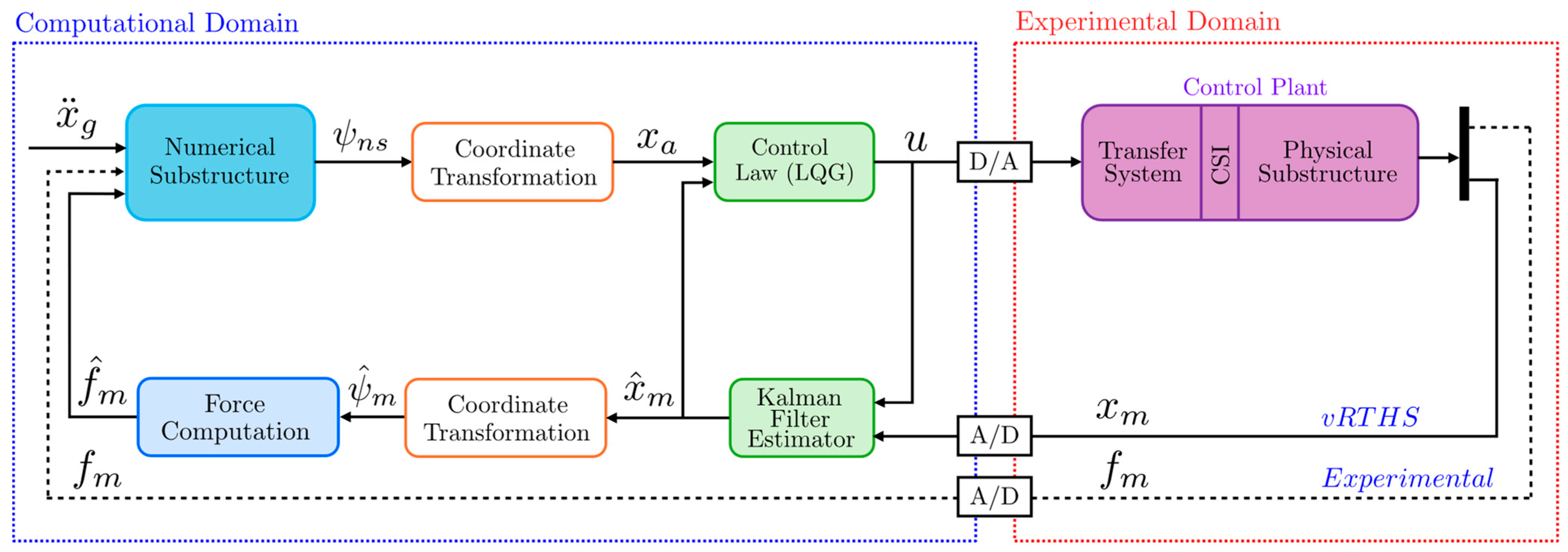
The primary objective of this benchmark problem is to develop a control algorithm that enables the control plant output (measured actuator displacements) to follow the target displacement vector (numerical substructure’s response in actuator coordinates), while evaluating both the tracking accuracy and the overall performance of the RTHS. In the v-maRTHS, experimental plant is replaced with a nominal plant model based on the experimental data and is represented in state–space form. Figure 4 presents the architecture of the v-maRTHS benchmark framework. The numerical substructure computes target interface displacements in frame coordinates, which are transformed into actuator coordinates and enforced on the physical specimen after the compensation procedure via a MIMO controller. The resulting actuator displacements are measured, filtered, and transformed back into frame coordinates to compute feedback forces and interface states. These feedback signals are returned to the numerical substructure to maintain equilibrium and compatibility across the interface in real time. The modular layout allows for the integration of MIMO controllers and estimation strategies to enhance tracking performance and system identification accuracy under uncertainty.

2.4. MIMO Controller Application in the maRTHS Benchmark

2.4.1. Reference Controller—Linear Quadratic Gaussian (LQG) Control

In the maRTHS benchmark problem, a simple LQG control was chosen by Condori et al. [48] as reference controller to offer adequate performance, due to its convenience introducing uncertainty as additive noise in a state–space framework. The LQG controller is a closed-loop control strategy that integrates two principal components: (1) a deterministic LQG control that provides optimal feedback gains and (2) a Kalman filter that estimates unmeasured states required for feedback in real-time.
As shown in Figure 5, the numerical substructure computes the total dynamic response Ψ n s after the seismic excitation application via the ground acceleration input x ¨ g . The vector Ψ n s includes translational and rotational DOFs. Because hydraulic actuators generate only linear translational motion, it is necessary to perform a coordinate transformation from frame coordinates to the actuator coordinates. After coordinate transformation, the required interface displacement x a is generated and passed to the controller. The LQG controller then forms the tracking error e = x a x m and builds an augmented state z a = z , e T yielding the command signal as
u = K p K e z e
where K p and K e come from the quadratic cost function defined by
J = 0 z a T Q z a + u T R u d t
where Q and R are the weighting matrices to minimize the cost function J .
The command signal u is converted from digital to analog (D/A) and sent to the experimental domain, which moves the physical substructure accordingly. The resulting measured displacement x m is digitized (A/D) and then fed back to the computational domain. An estimator is required because the measured signals are affected by high-frequency noise, and some system states are not directly measured. The Kalman filter estimator filters out the high-frequency components. The resulting estimated state is then utilized by the control law to compute the control input in the next steps, which is subsequently applied to the control plant. The system compensates for CSI effects and actuator dynamics to maintain real-time accuracy and stability. A coordinate transformation yields Ψ ^ m vector for force equilibrium and tracking error analysis. Finally, the interface force f ^ m is calculated and fed back into the numerical substructure to complete the RTHS loop.

2.4.2. Proposed Controller—Adaptive Discrete Feedforward Control (ADFC)

The proposed ADFC builds upon the feedforward delay compensation method originally developed for model-based feedforward (MFF) controllers [59,60,61]. The ADFC strategy was implemented into the v-maRTHS benchmark problem to enhance command tracking performance and estimation accuracy at the physical-numerical interface. The performance of the ADFC is evaluated relative to the reference LQG control method.
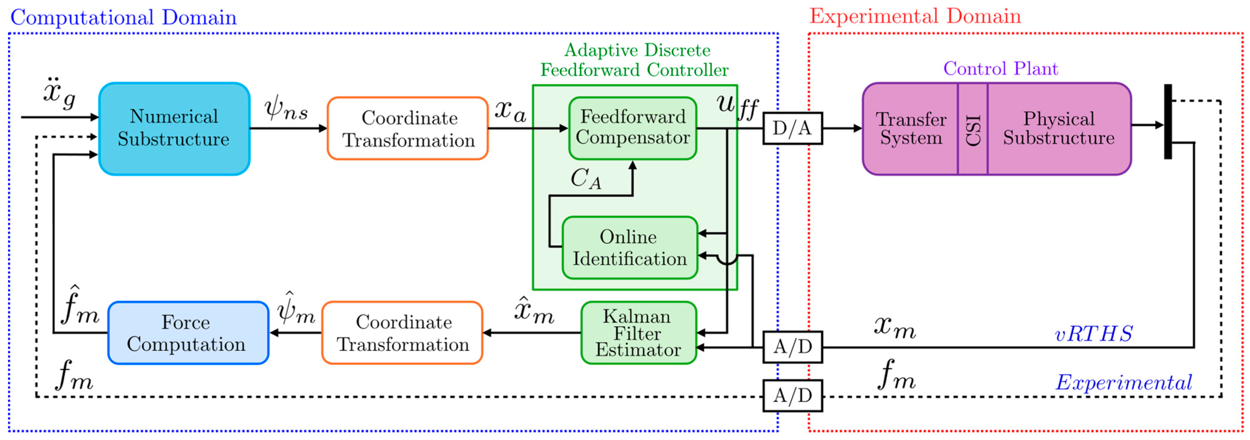
The MIMO controller block in v-maRTHS framework was replaced by the ADFC as shown in Figure 6. The ADFC computes the control input for each actuator channel independently using the polynomial feedforward law. It introduces a real-time compensation layer that directly addresses tracking inaccuracies arising from actuator dynamics and CSI. After the numerical substructure computes the interface displacement x a , it is passed to the feedforward controller, which operates within the MIMO controller module alongside the Kalman filter estimator. The ADFC generates a feedforward command u = u f f using a FIR filter whose coefficients C A are not fixed but are adaptively updated online. This update is performed through the least squares estimation that relates to the recent history of actuator commands and the corresponding numerical interface displacements, forming a buffer of length N b over a window T b . The compensated actuator command is sent to the control plant, while the measured actuator response is used for Kalman filter-based state estimation and for continuously refining the FIR coefficients. This real-time identification mechanism enables the ADFC to maintain actuator tracking accuracy without explicit reliance on pre-testing for tuning the control coefficients.
In the decentralized ADFC formulation, each actuator independently adapts its feedforward coefficients using a shared regressor derived from the multi-axial interface response, thereby embedding inter-actuator coupling effects within the adaptive law without requiring an explicit coupled plant model.
The implementation follows a recursive control loop in which real-time measurements and commands are processed using derivative mappings and buffered data, enabling real-time system identification and feedforward control. Each loop cycle comprises six detailed stages: (1) frame-to-actuator transformation, (2) derivative mapping and buffering, (3) adaptive coefficient identification, (4) predictive control input computation, (5) experimental enforcement, and (6) frame-coordinate feedback for restoring force calculation.
The simulation starts with the numerical substructure solving for target interface displacements ψ n s = x k = ψ n s , 4 k , θ k = ψ n s , 28 ( k ) T , consisting of translational and rotational DOFs in frame coordinates at time step k. This vector is transformed into actuator space as follows:
x a k = x a , 1 k x a , 2 k = x ( k ) + p · { c o s α 1 + θ ( k ) c o s α 1 } x ( k ) + p · { c o s α 2 + θ ( k ) c o s α 2 } R 2 x 1
where α 1 and α 2 are the inclination angles of actuators 1 and 2 (measured from horizontal axis), p is the moment arm length, and x a k serves as the raw desired displacement vector to be sent to the two servo–hydraulic actuators. These target displacements are then passed to the ADFC compensator block, which adjusts them using an online-identified feedforward model of actuator dynamics.
Before identifying the actuator dynamics, each measured actuator displacement signals x m , 1 k and x m , 2 k undergoes derivative mapping to construct a regressor vector encoding temporal dynamics of the plant. Using five historical samples of each signal x m , i k j , j = [ 0 , , 4 ] , a vector of four entries is computed for each actuator through backward difference method (BDM) based on a second-order Taylor expansion over uniformly sampled signals with time step Δ t as
x m , i d k = x m , i k x ˙ m , i k x ¨ m , i k x m , i k = C D x m , i k x m , i k 1 x m , i k 2 x m , i k 3 x m , i k 4 , i = 1 , 2
where C D contains the coefficients of the BDM provided discrete approximations of the time derivatives as follows
C D = 1 0 0 0 0 3 2 Δ t 4 2 Δ t 1 2 Δ t 0 0 2 Δ t 2 5 Δ t 2 4 Δ t 2 1 Δ t 2 0 5 2 Δ t 3 18 2 Δ t 3 14 2 Δ t 3 3 2 Δ t 3 0 .
To analyze the recent behavior of actuator i , these mapped derivative vectors are further buffered as a regressor matrix U m i ( k ) over the recent time horizon as follows:
U m , i k = x m , i k x ˙ m , i k x ¨ m , i k x m , i k x m , i k 1 x ˙ m , i k 1 x ¨ m , i k 1 x m , i k 1 x m , i k N b + 1 x ˙ m , i k N b + 1 x ¨ m , i k N b + 1 x m , i k N b + 1 R N b × 4 .
where i   = 1 ,   2 . Each row of U m , i ( k ) represents the local temporal state of the actuator i over the past N b = 1024 samples at a given past time instant and serves as an input for estimating the actuator’s control dynamics. The ADFC parameters were adopted from the prior SISO study, where detailed parametric analyses demonstrated that a buffer length of N b = 1024 (1 s window at 1024 Hz) achieves an effective balance between estimation accuracy and computational efficiency, providing a 1 Hz frequency resolution.
Then, the augmented regressor matrix for two actuators is assembled as
P k = [ U m , 1 k ,   U m , 2 k ] R N b × 8 .
Although the command to each actuator is computed independently, the identifier observes both actuators at once through the augmented regressor, which lets the coefficients adapt in the presence of cross-coupling. This regressor matrix is used as the input data to the online identifier block to estimate the adaptive coefficient matrix C A ( k ) by using the least squares estimation as
C A k = P ( k ) P ( k ) 1 P ( k ) U f f ( k ) R 8 × 2
where U f f k contains the buffered feedforward actuator command history as
U f f k = u 1 k u 2 k u 1 k N b + 1 u 2 k N b + 1 R N b × 2 .
To ensure robustness, the matrix inversion is carried out via lower-upper (LU) decomposition, and a fixed default C 0 is used in the first few seconds of simulation or if d e t P ( k ) P ( k ) = 0 , which implies that no feedforward correction is applied until the buffer duration has passed. The buffer duration T b and update rate f b are crucial design parameters. The buffer length N b is chosen such that:
T b = N b · Δ t
f b = 1 Δ t N b N o
where Δ t is the discretization time step, and N o is the overlap length between two consecutive buffer vectors. The controller begins operation after time T b , once sufficient history of x m k and u ff k is available to populate the matrices P and U ff .
To implement the feedforward compensation, the desired displacements, x a , 1 k and x a , 2 k , are processed similarly with the measured displacements as follows:
x a , i d k = x a , i k x ˙ a , i k x ¨ a , i k x a , i k = C D x a , i k x a , i k 1 x a , i k 2 x a , i k 3 x a , i k 4 , i = 1 , 2
where they are multiplied with C D given in Equation (17) to obtain derivative variables x a , 1 d k and x a , 2 d k R 4 x 1 and can be represented as an augmented regressor vector as
x a , i r e g k = x a , 1 d k x a , 2 d k R 8 x 1 .
Finally, the compensated displacement vector is obtained as follows:
u f f = u 1 k u 2 k = C A k · x a r e g k   R 2 x 1 .
This prediction incorporates actuator coupling through the full-rank C A k R 8 × 2 coefficient matrix and thus anticipates multi-axial tracking behavior. The execution flow for the ADFC block is demonstrated in Figure 7.
Next, the commands, u 1 k , u 2 k T , are sent to the two hydraulic actuators. Upon execution of these commands, the actuators produce physical displacements denoted by x m , 1 k and x m , 2 k . These are measured via displacement sensors and are used to assess how accurately the experimental substructure followed the numerical command. However, these measurements are subject to sensor noise and may not be directly reliable for state estimation. To enhance the accuracy of the state information, the measured displacements are passed through a Kalman filter to estimate the true system states from noisy sensor data. The Kalman filter is modeled in discrete-time state–space form as
z ˙ = A z + B u f f + w k
x m = C z + D u f f + v k
where z is the internal state vector of the experimental substructure (e.g., interface displacements); x m is the measured actuator displacement vector; u f f is the actuator command vector; w k and v k are zero-mean Gaussian noise processes representing process noise and measurement noise, respectively; A , B , C and D are the nominal system matrices of the control plant. Using this model, the Kalman filter computes an optimal estimate of the interface response, yielding
x ^ m k = x ^ m , 1 k x ^ m , 2 k R 2 x 1 .
The estimated signals, x ^ m , 1 and x ^ m , 2 , are subsequently transformed back into global frame coordinates as
ψ ^ m = x ^ k θ ^ k = x ^ m , i k p [ c o s α i + θ k c o s α i ] a r c s i n x ^ m , 1 k x ^ m , 2 k 2 p   s i n α 2   R 2 x 1 .
In this study, the Kalman filter is applied to actuator displacement signals because the maRTHS benchmark represents a virtual RTHS configuration in which actuator displacements are the primary measured variables and interface forces are computed numerically; in a physical RTHS implementation, the same estimation structure could equivalently be applied to measured interface forces from load cells. Extending the filter to force measurements introduces two key challenges: (1) it requires an accurate model linking displacement and restoring force, which in RTHS is often nonlinear; and (2) it increases computational delay due to filtering and synchronization of force signals, potentially affecting estimation bandwidth and stability.
Once the estimated global interface displacements, x ^ k ,   θ ^ k T , are obtained, they are passed to the restoring force calculation block. Although the built-in load cells on the actuators in the experimental setup measure the restoring force ( f m ), these force readings are unsuitable for direct use because they are dominated by the coupler’s inertial effects, which is not a component of the original frame. Consequently, the force vector solely attributed to the frame is estimated as
f ^ m k = M E . ψ ¨ ^ m + C E . ψ ˙ ^ m + K E . ψ ^ m .
The restoring force vector f ^ m k typically includes lateral force and moment as
f ^ m k = F ^ 4 k M ^ 28 k R 2 x 1 .
These forces are calculated and then fed back to the numerical substructure to complete the RTHS loop.

2.5. Evaluation Criteria and Performance Assessment

To evaluate the effectiveness of the ADFC in maRTHS, a comprehensive set of performance indices was used, categorized into tracking control, estimation accuracy, and global system response as outlined in Table 3. The tracking control metrics assess the actuator’s ability to follow the desired command signal, focusing on time delay, normalized error, and peak error between the target and measured actuator displacements. The estimation category evaluates the accuracy of estimating interface displacements, comparing the target and estimated values to quantify time delay, normalized and peak estimation errors. The global RTHS metrics measure the overall fidelity of the RTHS by comparing the simulated and estimated responses between the reference structure and the hybrid system at both the interface node and the upper stories (nodes 2 and 3), using normalized and peak relative error indicators.

3. Results

Virtual maRTHSs were performed using the proposed ADFC strategy and compared against the reference LQG controller. Simulations considered nominal and plant conditions with uncertainties subjected to El Centro (1940), Kobe (1995), and Morgan Hill (1984) ground motions scaled to 0.40 of the peak ground acceleration (PGA). Actuator displacement tracking, interface response accuracy, and system identification metrics were evaluated by over 1000 random control plant models.
Table 4 compares the effectiveness of the reference controller (LQG) with the ADFC in reducing tracking and estimation errors considering the mean values over three ground motions for both the experimental plant and nominal (identified) plant, where no modeling uncertainties are introduced. The ADFC consistently enhances most performance indices relative to the LQG. In the tracking control category, the most significant improvements are observed for Actuator 2, with tracking delay reduced from 2.90 ms to 0.98 ms (J1,2), normalized tracking error from 9.40% to 2.46% (J2,2), and peak tracking error from 10.30% to 2.92% (J3,2). Similarly, estimator delay shows the largest reduction for Actuator 2, decreasing from 2.90 ms to 0.98 ms (J4,2). Among interface DOFs, the most notable improvements occur at the rotational DOF (node 28), where the normalized estimation error decreases from 17.80% to 2.59% (J5,28), and the peak estimation error from 18.80% to 3.88% (J6,28).
For global RTHS performance, the most pronounced improvement in normalized global error occurs for J7,28, decreasing from 16.80% to 7.33%, while the corresponding peak error (J9,28) is reduced from 13.10% to 7.02%. In contrast, the performance at upper stories (nodes 2 and 3) shows that the ADFC produces slightly larger values for these metrics than the LQG. When ADFC reduces phase lag and improves interface tracking, the motion at the interface ends up containing more high-frequency components. This extra high-frequency content may excite higher vibration modes in the numerical substructure, which J8 and J10 indices are particularly sensitive. Whereas the LQG controller suppresses those higher modes by using quadratic weights (Q and R) and applying a Kalman filter in the feedback path. The mean experimental results obtained by using LQG control are also provided to show how actuator dynamics together with the coupler and control-structure interaction degrade tracking and estimation performance compared with an identified nominal plant without uncertainty.
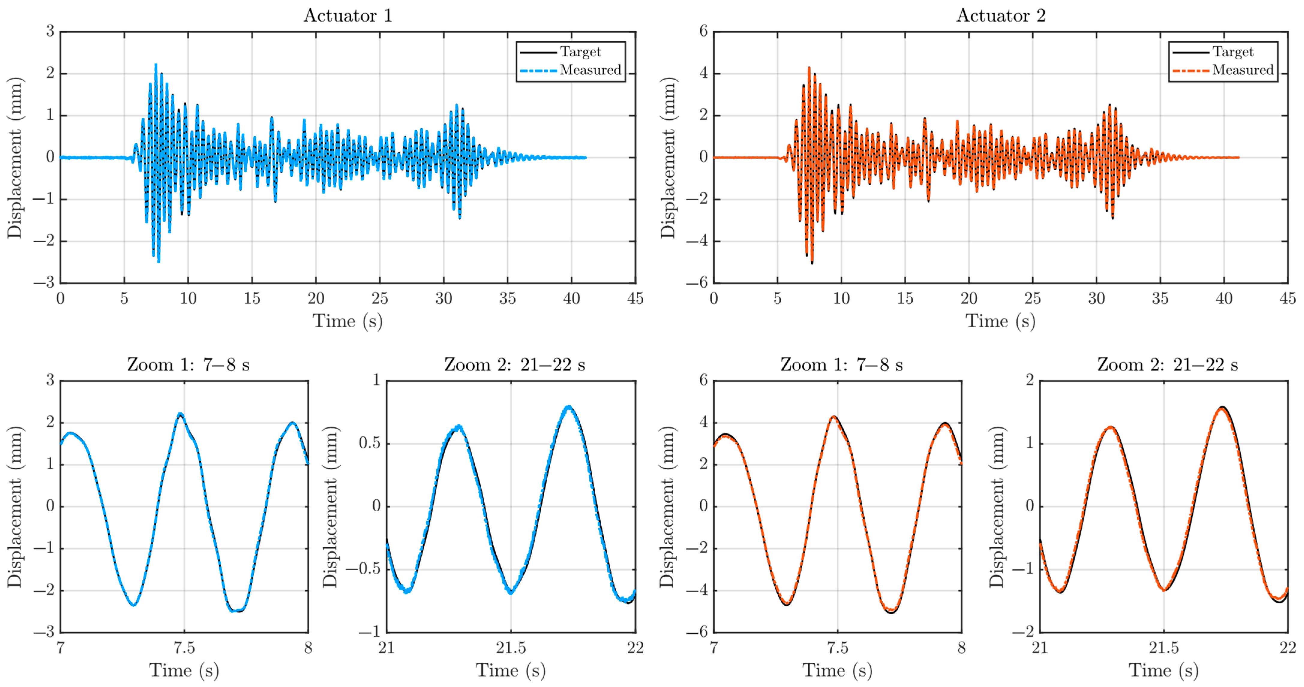
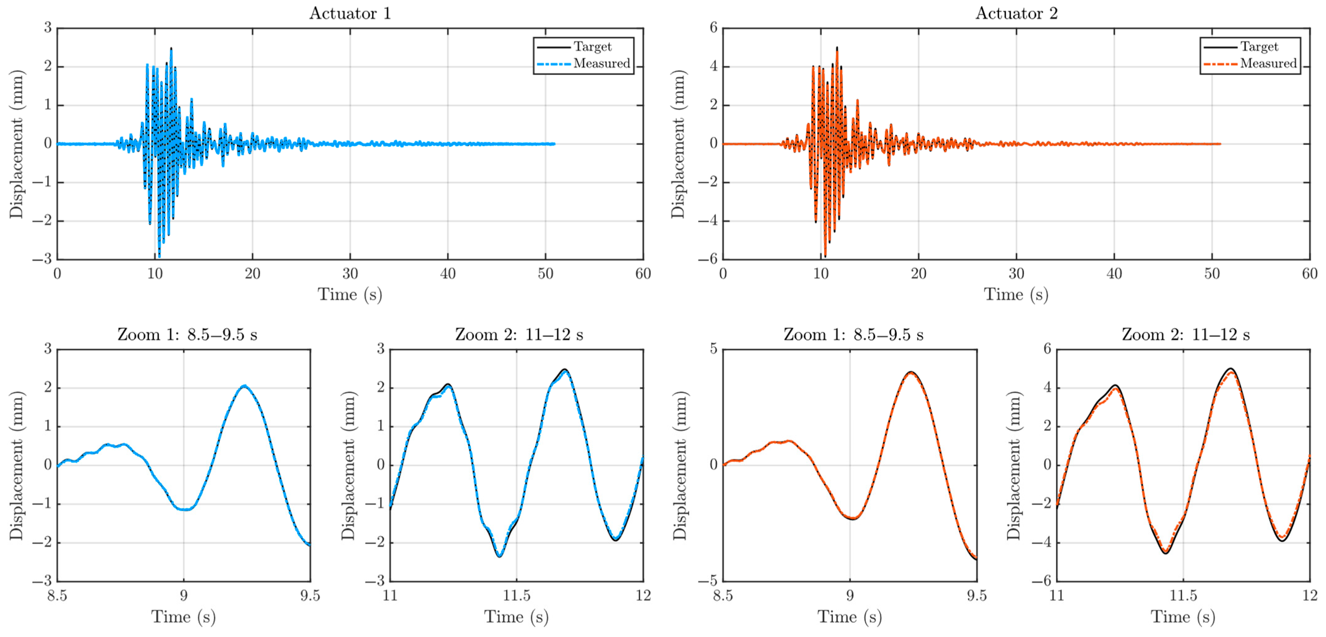
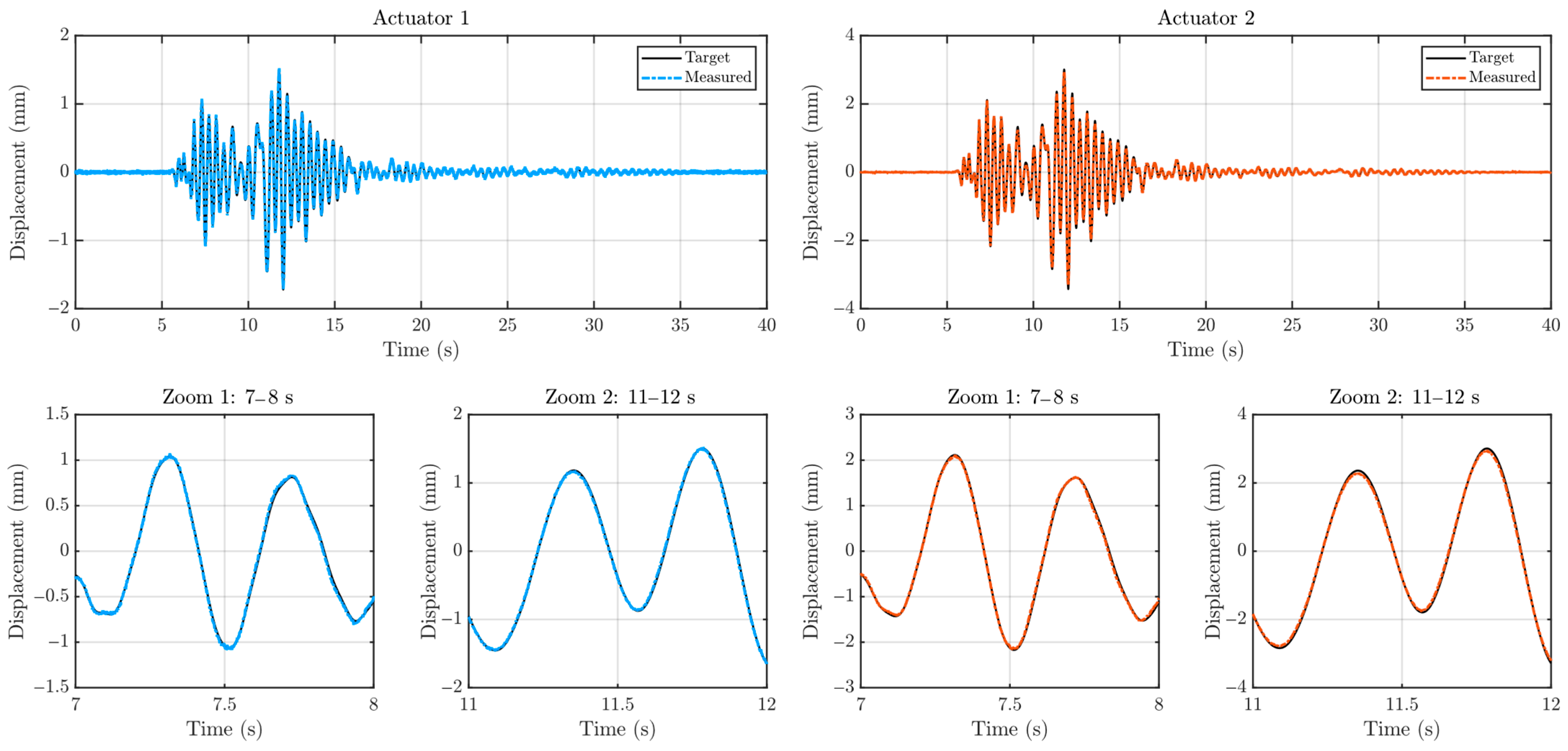
Figure 8, Figure 9 and Figure 10 illustrate the actuator displacement tracking performance under the El Centro, Kobe, and Morgan Hill ground motion inputs (scaled to 40% PGA) for the v-maRTHS configuration with plant uncertainties (Trial #1). In each case, the top row presents the full-time history comparison between the measured and target actuator displacements, while the bottom row highlights zoomed-in views over chosen time windows to evaluate local tracking performance. Quantitative tracking indicators support visual observations. The average time delay error (J1) is 0.98 ms for both actuators. The average normalized root mean square errors (J2) are 5.03% and 2.83% for actuators 1 and 2, respectively, while the average maximum peak errors (J3) are 3.52% and 2.54%. These values indicate minimal overshoot throughout the simulation under uncertainty. The results validate the controller’s capability to deliver high-fidelity simulation under multi-axial seismic demands with control plant uncertainties.
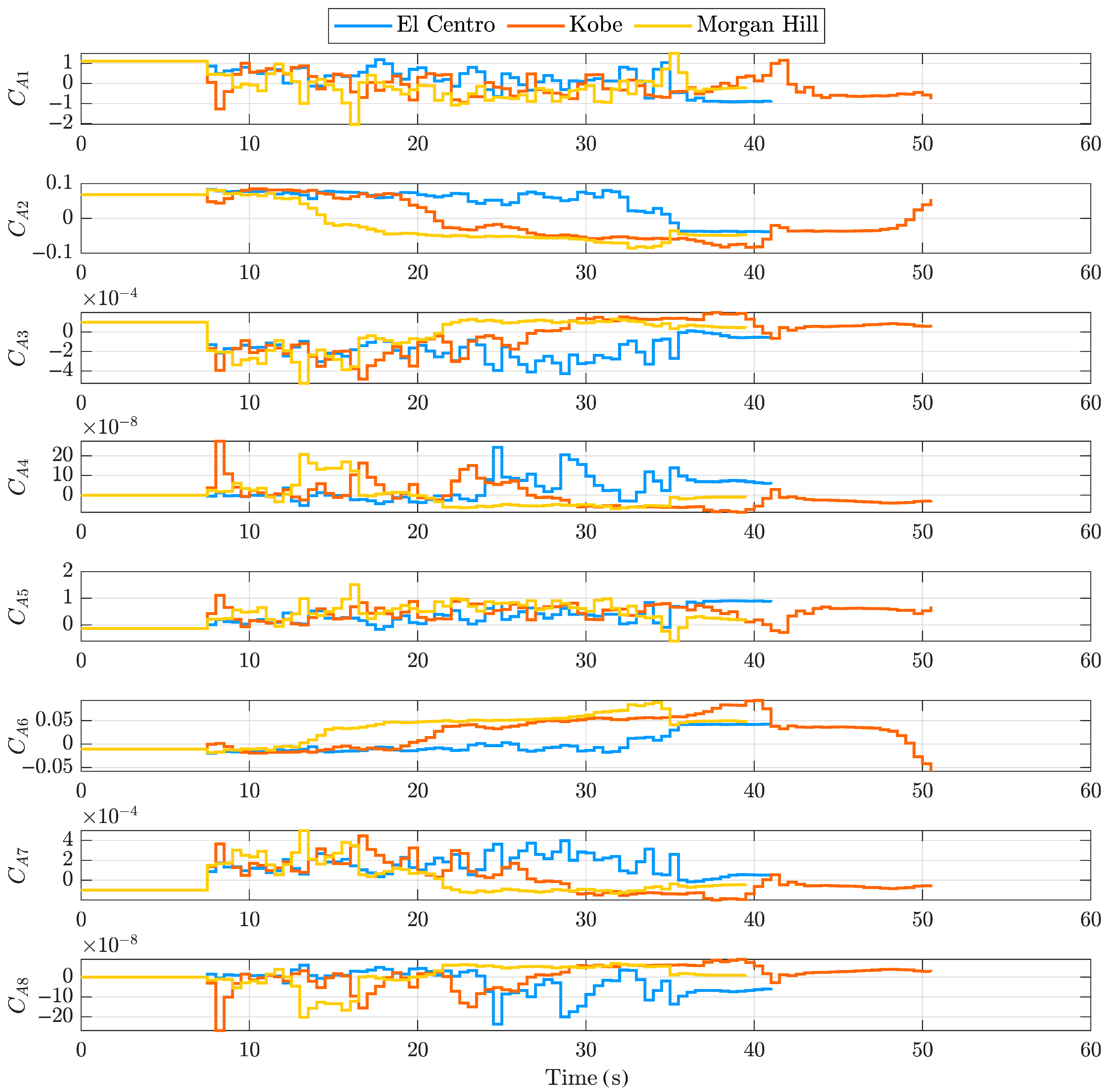
The time histories of the identified ADFC coefficients for Actuator 1 considering three ground motions are presented in Figure 11. The coefficients initially start from the nominal value vector C 0 1   0   0   0   0   0   0   0 T . As the structural response develops under seismic excitations, the coefficients exhibit adaptive fluctuations in response to the evolving dynamic characteristics of the system. As the input excitation diminishes and the structural vibrations decay, the coefficients gradually stabilize, converging toward steady values. The bounded evolution of all coefficients across the different earthquake ground motions confirms the stability under varying dynamic conditions, reflecting the effective online adaptation of the ADFC. Although a formal stability analysis is not presented, numerical results consistently showed bounded actuator commands and convergent adaptive coefficients throughout all simulations, indicating that stability was maintained under all tested uncertainties.
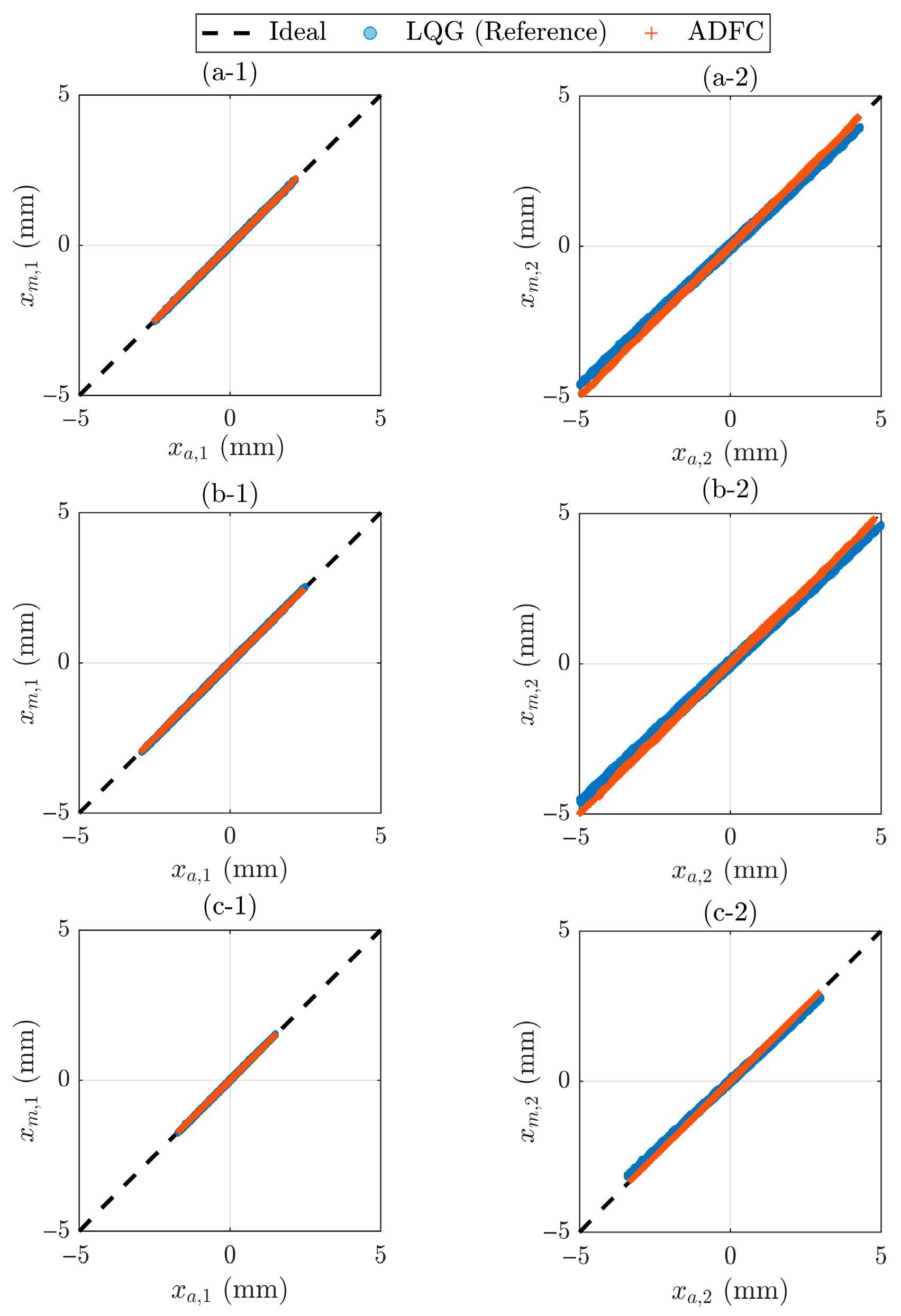
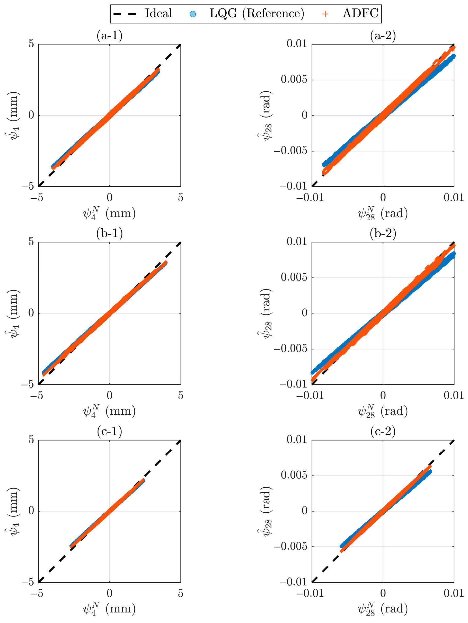
The synchronization subspace plots in the actuator and interface coordinates (see Figure 12 and Figure 13) provide clear insight into the comparative tracking and estimation performance between the ADFC and reference LQG controller. In the actuator coordinates, both controllers demonstrate high tracking fidelity, with the data points densely clustered around the 45-degree line (ideal) for both actuators across all earthquake ground motions. Notably, the ADFC exhibits slightly improved performance with a tighter concentration of data points along the diagonal, indicating better alignment between the target and measured actuator displacements. This suggests that the adaptive mechanism of ADFC more effectively compensates for unmodeled dynamics and system variations encountered during v-maRTHS. Similarly, for the interface coordinates (DOF 4 and DOF 28), the estimated interface displacements closely match the reference line for both control strategies. However, the ADFC again demonstrates better estimation, with data points exhibiting slightly reduced dispersion and stronger alignment with the ideal line, especially for the rotational DOF 28. This consistent trend across both actuator and interface subspaces highlights the advantage of the adaptive feedforward correction mechanism, which continuously tunes the control based on real-time tracking errors, leading to enhanced overall synchronization while maintaining stability.
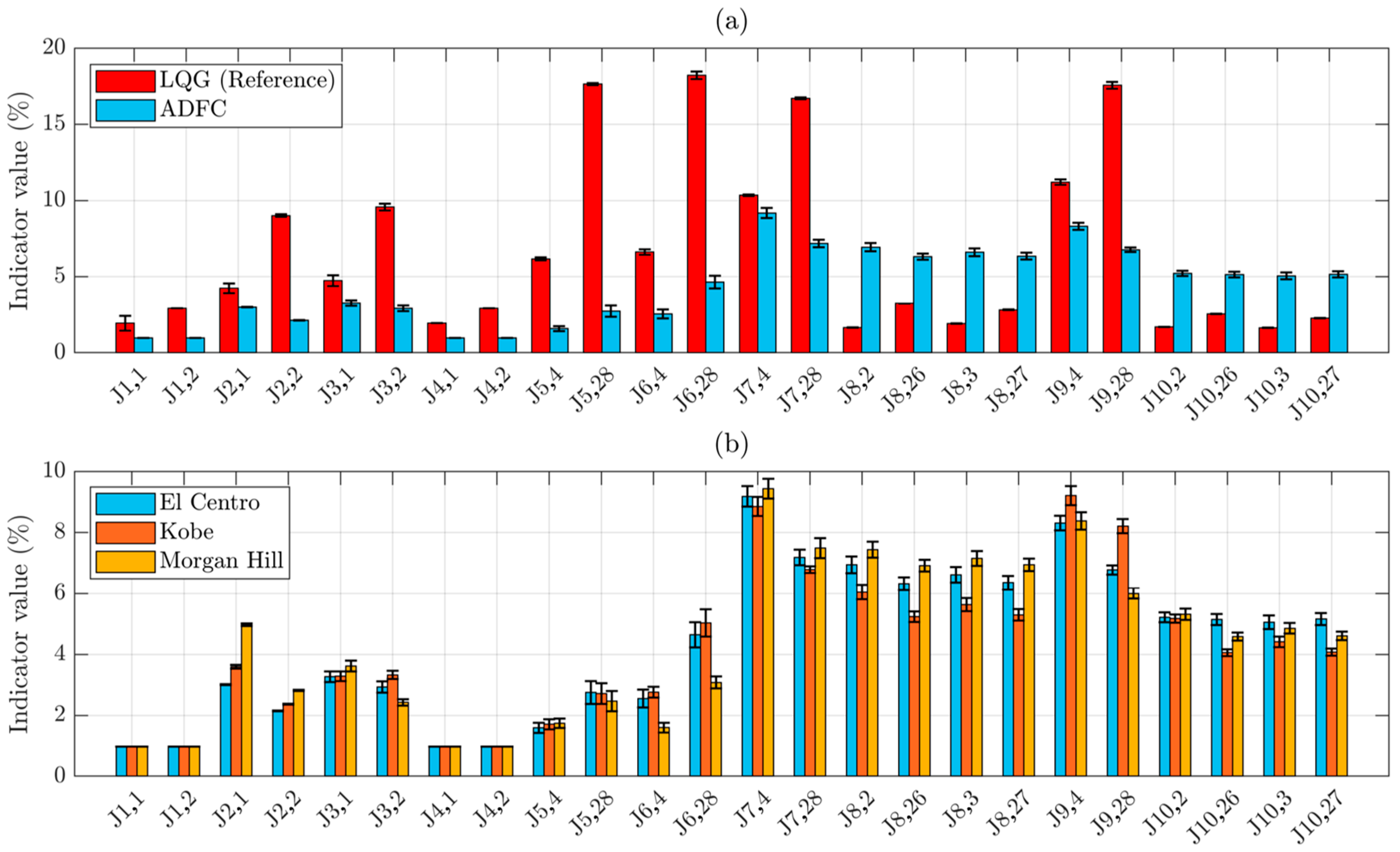
Figure 14a illustrates the median and interquartile range of the performance indicators derived from 1000 v-maRTHSs under El Centro excitation (scaled to %40 PGA), comparing the reference LQG controller with the ADFC. As shown, ADFC consistently outperforms the LQG controller in tracking and interface estimation indicators (J1–J6). Specifically, indicators J1–J3 show significantly reduced median values for the ADFC, indicating improved tracking accuracy and minimal time delay at both actuators. The interquartile ranges of these indices are also notably smaller, reflecting improved robustness of tracking performance under modeling uncertainties and excitation variability. Similarly, estimation at the physical-numerical interface (J4–J6) benefits from the enhanced actuator response, leading to tighter agreement between target and observed states.
In contrast, the global RTHS performance indices that quantify upper-story relative responses, J8 and J10, are slightly larger with the ADFC than with the LQG. This outcome is consistent with the control objectives of the two control schemes. By reducing phase lag at the interface DOFs, the ADFC increases the effective bandwidth of the interface motion, thereby increasing the higher-mode participation within the numerical substructure. Residual imperfections in actuator cross-coupling, coordinate mapping, or force reconstruction subsequently cause discrepancies in upper-story relative motion between the numerical substructure and the reference model, to which J8 and J10 are particularly sensitive. Additionally, while the ADFC improves the fidelity of actuator motion, the estimator is still based on a linear nominal model and may not fully propagate the benefits of enhanced tracking to global state predictions. This mismatch results in accumulated estimation errors at upper stories and non-collocated DOFs, especially under scenarios where global dynamic interactions are prominent.
In Figure 14b, the ADFC results are shown for three ground motions, all scaled to 40% PGA. The trends are generally consistent across ground motions, reflecting the robustness of ADFC’s tracking and local estimation improvements. In particular, the largest errors for the majority of the performance indices were obtained under the Morgan Hill earthquake ground motion.
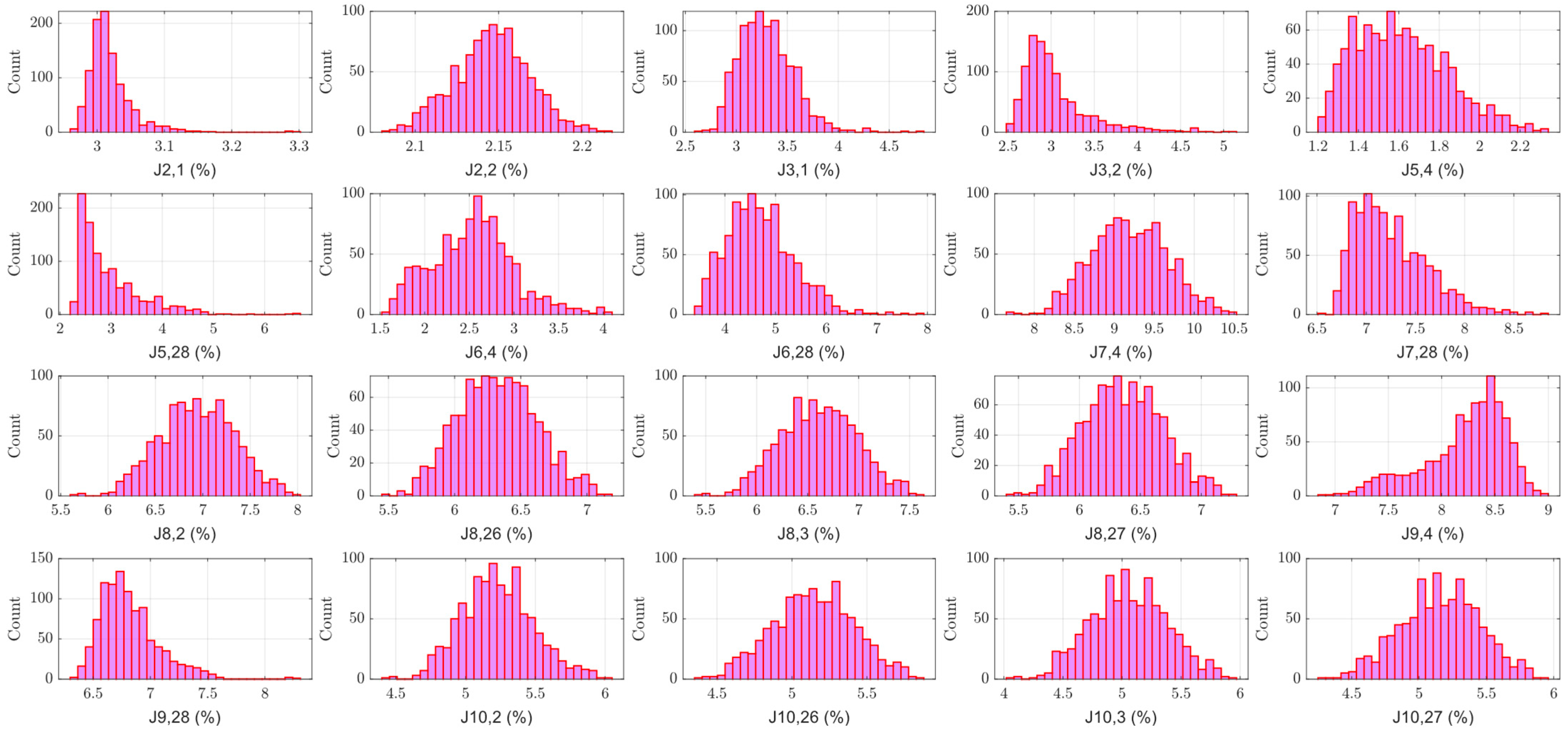
Figure 15 presents histograms of performance indices J2 through J10 obtained from 1000 v-maRTHSs utilizing the ADFC under the El Centro ground motion scaled to 40% PGA. The tracking-related indicators (J2,1–J3,2), which quantify amplitude errors for actuator displacements, are highly concentrated around low values. This indicates that the actuator-level tracking performance remains consistently accurate across the ensemble of simulations. The narrow spread of these histograms suggests reliable actuator control under the presence of plant uncertainties.
For the interface matching indices (J5,4–J6,28), which assess how well the interface responses of the experimental substructure match the numerical predictions, the distributions are wider, especially for the rotational interface DOF 28. This indicates a higher sensitivity to model variability in rotational coordinates. The variation across J6-type indicators suggests that the rotational dynamics are more prone to fluctuation under uncertainty.
The estimation-related indicators (J8–J10), which measure the accuracy of unmeasured state estimation, exhibit the broadest and mostly symmetric distributions, and hence higher degree of variability across random simulation trials. Specifically, J9,4 shows a notable extension toward higher error values, indicating occasional degradation in estimation quality. This is expected given the challenge of estimating internal states using limited measurements under uncertain plant dynamics. These results underline the relative difficulty in achieving consistently low estimation error compared to actuator tracking or interface matching.

4. Conclusions

This study extended the adaptive discrete feedforward controller (ADFC) from uniaxial to multi-axial actuator control and demonstrated its application within a virtual multi-axial real-time hybrid simulation (v-maRTHS) framework under seismic excitations. The ADFC was implemented as a model-based outer-loop compensator. The controller dynamically adapts its feedforward compensation by updating the coefficients of a finite impulse response filter using least squares estimation of recent actuator tracking errors. The controller operates in real time, continually mapping the reference actuator trajectory to a feedforward compensation signal. This design makes the ADFC well-suited for hybrid simulation platforms where system dynamics may vary due to plant uncertainties or excitation-dependent nonlinearities.
Through extensive v-maRTHSs involving 1000 random trials under three ground motion inputs, the proposed ADFC strategy demonstrated consistently improved results for the majority of the performance indicators compared to the reference LQG controller. Time history plots confirmed that ADFC significantly reduced phase and amplitude errors between target and measured actuator displacements. The median time delay (J1) was found to be below 1 ms for both actuators, with NRMS errors (J2) and peak errors (J3) reduced to under 5%. Similarly, interface estimation metrics (J4–J6), particularly for the collocated DOFs, demonstrated improved accuracy and reduced variability with the ADFC.
While ADFC demonstrated superior performance at the local actuator level, the global estimation metrics (J8–J10), which evaluate the accuracy of reconstructed states at uninstrumented locations, exhibited greater variability. This outcome is consistent with the ADFC’s adaptive feedforward update law, which enhances delay compensation and reduces phase lag without imposing a global bandwidth constraint. Because the controller adapts within a 0–30 Hz range that overlaps with the structure’s first five natural modes (2.29–29.91 Hz), its increased control activity near the upper end of this range can introduce small additional energy into the higher modes. In the presence of minor uncertainties in coordinate transformation or restoring-force estimation, these higher-mode contributions amplify relative discrepancies in the global response metrics. In contrast, the LQG controller enforces a globally optimized trade-off between tracking and response fidelity by penalizing high-frequency control effort, thereby suppressing higher-mode participation but retaining more phase lag. The indirect impact of ADFC’s improved local tracking on the Kalman filter–based estimation of internal states suggests that enhanced tracking alone may not guarantee improved system-level identification unless estimator dynamics are also co-optimized. Nevertheless, the ADFC maintained stable performance across all Monte Carlo trials, and the observed differences remained within bounded limits, indicating robust convergence despite localized variations in modal participation.
The advantages of the ADFC include ease of implementation due to its model-based structure, low computational complexity from the use of standard least squares estimation, and flexibility in tuning with initial coefficient vectors derived from open-loop test data. Moreover, its stability and robustness in both nominal and uncertain plant conditions make it a good solution for improving simulation fidelity in RTHS, especially in multi-axial systems. Future work may investigate enhanced online identification methods such as weighted or recursive least squares, or adaptive Kalman filtering, to further improve estimation quality. While the present work demonstrates the effectiveness of the ADFC through extensive virtual benchmark simulations, it is acknowledged as a current limitation that the methodology has not yet been experimentally implemented. Experimental implementation using physical actuators and interface sensors will also be essential to evaluate the ADFC’s performance in real-time, hardware-in-the-loop environments, accounting for sensor noise, bandwidth constraints, and real-world delay characteristics.

Author Contributions

Conceptualization, M.C. and J.T.; data curation, M.C.; formal analysis, M.C.; funding acquisition, J.T. and O.M.; investigation, M.C.; methodology, M.C. and J.T.; project administration, M.C.; software, M.C. and J.T.; supervision, O.M.; validation, M.C. and J.T.; visualization, M.C.; writing—original draft, M.C.; writing—review and editing, J.T. and O.M. All authors have read and agreed to the published version of the manuscript.

Funding

This paper is based upon work funded by the Natural Sciences and Engineering Research Council of Canada (NSERC Discovery Grant RGPIN-2022-05127), the Natural Science Basic Research Program of Shaanxi Province (2025JC-YBQN-538), and the Fundamental Research Funds for the Central Universities, Chang’an University (No. 300102285103). Any opinions, findings, conclusions, and recommendations expressed here are those of the authors and do not necessarily reflect the views of the sponsors.

Data Availability Statement

The data that support the findings of this study are available from the corresponding author upon reasonable request.

Conflicts of Interest

The authors declare no conflicts of interest.

References

  1. Gao, X.; Castaneda, N.; Dyke, S.J. Experimental validation of a generalized procedure for MDOF real-time hybrid simulation. J. Eng. Mech. 2014, 140, 04013006. [Google Scholar] [CrossRef]
  2. Friedman, A.; Dyke, S.J.; Phillips, B.; Ahn, R.; Dong, B.; Chae, Y.; Castaneda, N.; Jiang, Z.; Zhang, J.; Cha, Y.; et al. Large-scale real-time hybrid simulation for evaluation of advanced damping system performance. J. Struct. Eng. 2015, 141, 04014150. [Google Scholar] [CrossRef]
  3. Gomez, D.; Dyke, S.J.; Maghareh, A. Enabling Role of Hybrid Simulation Within the NEES Infrastructure in Advancing Earthquake Engineering Practice and Research; Intelligent Infrastructure Systems Laboratory (IISL): West Lafayette, IN, USA, 2014. [Google Scholar] [CrossRef]
  4. Williams, M.S.; Blakeborough, A. Laboratory testing of structures under dynamic loads: An introductory review. Philos. Trans. R. Soc. A Math. Phys. Eng. Sci. 2001, 359, 1651–1669. [Google Scholar] [CrossRef]
  5. Gao, X. Development of a Robust Framework for Real-Time Hybrid Simulation: From Dynamical System, Motion Control to Experimental Error Verification. Ph.D. Thesis, Purdue University, West Lafayette, IN, USA, 2012. [Google Scholar]
  6. Ahmadizadeh, M.; Mosqueda, G.; Reinhorn, A.M. Compensation of actuator delay and dynamics for real-time hybrid structural simulation. Earthq. Eng. Struct. Dyn. 2008, 37, 21–42. [Google Scholar] [CrossRef]
  7. Wallace, M.I.; Wagg, D.J.; Neild, S.A. An adaptive polynomial based forward prediction algorithm for multi-actuator real-time dynamic substructuring. Proc. R. Soc. A Math. Phys. Eng. Sci. 2005, 461, 3807–3826. [Google Scholar] [CrossRef]
  8. Darby, A.P.; Blakeborough, A.; Williams, M.S. Real-time substructure tests using hydraulic actuator. J. Eng. Mech. 1999, 125, 1133–1139. [Google Scholar] [CrossRef]
  9. Nakashima, M.; Masaoka, N. Real-time on-line test for MDOF systems. Earthq. Eng. Struct. Dyn. 1999, 28, 393–420. [Google Scholar] [CrossRef]
  10. Darby, A.P.; Williams, M.S.; Blakeborough, A. Stability and delay compensation for real-time substructure testing. J. Eng. Mech. 2002, 128, 1276–1284. [Google Scholar] [CrossRef]
  11. Zhao, J.; French, C.; Shield, C.; Posbergh, T. Considerations for the development of real-time dynamic testing using servo-hydraulic actuation. Earthq. Eng. Struct. Dyn. 2003, 32, 1773–1794. [Google Scholar] [CrossRef]
  12. Jung, R.Y.; Benson Shing, P.; Stauffer, E.; Thoen, B. Performance of a real-time pseudodynamic test system considering nonlinear structural response. Earthq. Eng. Struct. Dyn. 2007, 36, 1785–1809. [Google Scholar] [CrossRef]
  13. Chen, C.; Ricles, J.M. Analysis of actuator delay compensation methods for real-time testing. Eng. Struct. 2009, 31, 2643–2655. [Google Scholar] [CrossRef]
  14. Chen, C.; Ricles, J.M.; Marullo, T.M.; Mercan, O. Real-time hybrid testing using the unconditionally stable explicit CR integration algorithm. Earthq. Eng. Struct. Dyn. 2009, 38, 23–44. [Google Scholar] [CrossRef]
  15. Hayati, S.; Song, W. An optimal discrete-time feedforward compensator for real-time hybrid simulation. Smart Struct. Syst. 2017, 20, 483–498. [Google Scholar] [CrossRef]
  16. Chae, Y.; Kazemibidokhti, K.; Ricles, J.M. Adaptive time series compensator for delay compensation of servo-hydraulic actuator systems for real-time hybrid simulation. Earthq. Eng. Struct. Dyn. 2013, 42, 1697–1715. [Google Scholar] [CrossRef]
  17. Palacio-Betancur, A.; Gutierrez Soto, M. Adaptive tracking control for real-time hybrid simulation of structures subjected to seismic loading. Mech. Syst. Signal Process. 2019, 134, 106345. [Google Scholar] [CrossRef]
  18. Ning, X.; Wang, Z.; Wang, C.; Wu, B. Adaptive feedforward and feedback compensation method for real-time hybrid simulation based on a discrete physical testing system model. J. Earthq. Eng. 2022, 26, 3841–3863. [Google Scholar] [CrossRef]
  19. Song, W.; Dyke, S. Development of a cyber-physical experimental platform for real-time dynamic model updating. Mech. Syst. Signal Process. 2013, 37, 388–402. [Google Scholar] [CrossRef]
  20. Strano, S.; Terzo, M. Actuator dynamics compensation for real-time hybrid simulation: An adaptive approach by means of a nonlinear estimator. Nonlinear Dyn. 2016, 85, 2353–2368. [Google Scholar] [CrossRef]
  21. Huang, W.; Ning, X.; Ding, Y.; Wang, Z. A novel actuation dynamics adaptive compensation strategy for real-time hybrid simulation based on unscented Kalman filter. Int. J. Struct. Stab. Dyn. 2023, 23, 2350107. [Google Scholar] [CrossRef]
  22. Wang, Z.; Ning, X.; Xu, G.; Zhou, H.; Wu, B. High performance compensation using an adaptive strategy for real-time hybrid simulation. Mech. Syst. Signal Process. 2019, 133, 106262. [Google Scholar] [CrossRef]
  23. Ning, X.; Huang, N.W.; Xu, G.S.; Wang, Z.; Wu, B.; Zheng, L.; Xu, B. A novel model-based adaptive feedforward-feedback control method for real-time hybrid simulation considering additive error model. Struct. Control Health Monit. 2023, 2023, 5550580. [Google Scholar] [CrossRef]
  24. Wang, Z.; Xu, G.; Li, Q.; Wu, B. An adaptive delay compensation method based on a discrete system model for real-time hybrid simulation. Smart Struct. Syst. 2020, 25, 569–580. [Google Scholar] [CrossRef]
  25. Simpson, T.; Dertimanis, V.K.; Chatzi, E.N. Towards data-driven real-time hybrid simulation: Adaptive modeling of control plants. Front. Built Environ. 2020, 6, 570947. [Google Scholar] [CrossRef]
  26. Li, H.W.; Wang, F.; Ni, Y.Q.; Wang, Y.W.; Xu, Z.D. An adaptive and robust control strategy for real-time hybrid simulation. Sensors 2022, 22, 6569. [Google Scholar] [CrossRef]
  27. Niño, A.F.; Palacio-Betancur, A.; Miranda-Chiquito, P.; Amaya, J.D.; Silva, C.E.; Gutierrez Soto, M.; Giraldo, L.F. Deep Reinforcement Learning-Based Control for Real-Time Hybrid Simulation of Civil Structures. Int. J. Robust Nonlinear Control 2025, in press. [Google Scholar] [CrossRef]
  28. Xu, W.; Meng, X.; Chen, C.; Guo, T.; Peng, C. Evaluation of data-driven NARX model based compensation for multi-axial real-time hybrid simulation benchmark study. Front. Built Environ. 2024, 10, 1374819. [Google Scholar] [CrossRef]
  29. Nakata, N.; Spencer, B.F., Jr.; Elnashai, A.S. Multi-Dimensional Mixed-Mode Hybrid Simulation Control and Applications; Newmark Structural Engineering Laboratory Report Series 005; The Newmark Structural Engineering Laboratory: Urbana, IL, USA, 2007; Available online: https://hdl.handle.net/2142/3628 (accessed on 26 October 2025).
  30. Chen, C.; Ricles, J.M.; Hodgson, I.C.; Sause, R. Real-Time Multi-Directional Hybrid Simulation of Building Piping Systems. In Proceedings of the 14th World Conference on Earthquake Engineering, Beijing, China, 12–17 October 2008; Available online: https://www.iitk.ac.in/nicee/wcee/article/14_S16-01-007.PDF (accessed on 26 October 2025).
  31. Mercan, O.; Ricles, J.M.; Sause, R.; Marullo, T. Kinematic transformations for planar multi-directional pseudodynamic testing. Earthq. Eng. Struct. Dyn. 2009, 38, 1093–1119. [Google Scholar] [CrossRef]
  32. Al-Mahaidi, R.; Hashemi, M.J.; Kalfat, R.; Burnett, G.; Wilson, J. Multi-Axis Substructure Testing System for Hybrid Simulation; Springer: Singapore, 2018; Available online: https://link.springer.com/book/10.1007/978-981-10-5867-7 (accessed on 26 October 2025).
  33. Hashemi, M.J.; Al-Ogaidi, Y.K.F.; Wilson, J.; Abdouka, K. Collapse Simulation of Multi-Story RC Buildings Through Hybrid Testing. In Proceedings of the Australian Earthquake Engineering Society Conference, Lorne, Australia, 21–23 November 2014; Available online: https://aees.org.au/wp-content/uploads/2015/06/66-Hashemi.pdf (accessed on 26 October 2025).
  34. Phillips, B.M.; Spencer, B.F., Jr. Model-based multiactuator control for real-time hybrid simulation. J. Eng. Mech. 2013, 139, 219–228. [Google Scholar] [CrossRef]
  35. Fermandois, G.A.; Spencer, B.F., Jr. Development and Implementation of a Multi-Axial Real-Time Hybrid Simulation Framework; Newmark Structural Engineering Laboratory Report Series 049; The Newmark Structural Engineering Laboratory: Urbana, IL, USA, 2018; Available online: https://hdl.handle.net/2142/101441 (accessed on 26 October 2025).
  36. Najafi, A.; Fermandois, G.A.; Spencer, B.F., Jr. Decoupled model-based real-time hybrid simulation with multi-axial load and boundary condition boxes. Eng. Struct. 2020, 219, 110868. [Google Scholar] [CrossRef]
  37. Najafi, A.; Spencer, B.F. Multiaxial real-time hybrid simulation for substructuring with multiple boundary points. J. Struct. Eng. 2021, 147, 05021007. [Google Scholar] [CrossRef]
  38. Tian, Y.; Wang, T.; Zhou, H.; Du, C. Shaking-table substructure test using a MDOF boundary-coordinating device. Earthq. Eng. Struct. Dyn. 2022, 51, 3658–3679. [Google Scholar] [CrossRef]
  39. Elnashai, A.S.; Spencer, B.F.; Kuchma, D.A.; Yang, G.; Carrion, J.; Gan, Q.; Kim, S.J. The multi-axial full-scale sub-structured testing and simulation (MUST-SIM) facility at the University of Illinois at Urbana-Champaign. In Advances in Earthquake Engineering for Urban Risk Reduction; Springer: Dordrecht, The Netherlands, 2006; pp. 245–260. [Google Scholar] [CrossRef]
  40. Høgh, J.; Waldbjørn, J.; Wittrup–Schmidt, J.; Stang, H.; Berggreen, C. Quasi-Static Single-Component Hybrid Simulation of a Composite Structure with Multi-Axis Control. Strain 2015, 51, 459–473. [Google Scholar] [CrossRef]
  41. Tsokanas, N.; Abbiati, G.; Kanellopoulos, K.; Stojadinović, B. Multi-axial hybrid fire testing based on dynamic relaxation. Fire Saf. J. 2021, 126, 103468. [Google Scholar] [CrossRef]
  42. Huang, X.; Park, J.; Kwon, O.S. Network Interface Program for Actuator Controllers for Pseudo-Dynamic Hybrid Simulation. J. Earthq. Eng. 2024, 28, 266–287. [Google Scholar] [CrossRef]
  43. Kaufmann, W.; Beck, A.; Karagiannis, D.; Werne, D. Design, Construction and Capabilities of the Large Universal Shell Element Tester. In Proceedings of the 8th International Conference of the Spanish Association for Structural Engineering (ACHE 2022), Santander, Spain, 20–22 June 2022; Volume 73, pp. 83–88. [Google Scholar] [CrossRef]
  44. Mojiri, S.; Kwon, O.S.; Christopoulos, C. Development of a ten-element hybrid simulation platform and an adjustable yielding brace for performance evaluation of multi-story braced frames subjected to earthquakes. Earthq. Eng. Struct. Dyn. 2019, 48, 749–771. [Google Scholar] [CrossRef]
  45. Horiuchi, T.; Ohsaki, M.; Kurata, M.; Ramirez, J.A.; Yamashita, T.; Kajiwara, K. Contributions of E-Defense shaking table to Earthquake engineering and its future. J. Disaster Res. 2022, 17, 985–999. [Google Scholar] [CrossRef]
  46. Gomez, D.; Dyke, S.J.; Maghareh, A. Enabling role of hybrid simulation across NEES in advancing earthquake engineering. Smart Struct. Syst. 2015, 15, 913–929. [Google Scholar] [CrossRef]
  47. Van Den Einde, L.; Conte, J.P.; Restrepo, J.I.; Bustamante, R.; Halvorson, M.; Hutchinson, T.C.; Lai, C.T.; Lotfizadeh, K.; Luco, J.E.; Morrison, M.L.; et al. NHERI@UC San Diego 6-DOF large high-performance outdoor shake table facility. Front. Built Environ. 2021, 6, 580333. [Google Scholar] [CrossRef]
  48. Condori Uribe, J.W.; Salmeron, M.; Patino, E.; Montoya, H.; Dyke, S.J.; Silva, C.E.; Maghareh, A.; Najarian, M.; Montoya, A. Experimental benchmark control problem for multi-axial real-time hybrid simulation. Front. Built Environ. 2023, 9, 1270996. [Google Scholar] [CrossRef]
  49. Ruiz, S.; Song, W. Adaptive compensation for multi-axial real-time hybrid simulation via nonlinear parameter estimation. Front. Built Environ. 2024, 10, 1477804. [Google Scholar] [CrossRef]
  50. Aguila, A.J.; Li, H.; Palacio-Betancur, A.; Ahmed, K.A.; Kovalenko, I.; Gutierrez Soto, M. Conditional adaptive time series compensation and control design for multi-axial real-time hybrid simulation. Front. Built Environ. 2024, 10, 1384235. [Google Scholar] [CrossRef]
  51. Shangguan, Y.; Wang, Z.; Guo, Y.; Chen, Y.; Zeng, Y.; Zhou, H. Adaptive sliding-mode delay compensation for real-time hybrid simulations with multiple actuators. Front. Built Environ. 2024, 10, 1393710. [Google Scholar] [CrossRef]
  52. Quiroz, M.; Gálmez, C.; Fermandois, G.A. Robust decentralized adaptive compensation for the multi-axial real-time hybrid simulation benchmark. Front. Built Environ. 2024, 10, 1394952. [Google Scholar] [CrossRef]
  53. Tao, J.; Mercan, O. Adaptive discrete feedforward controller for tracking error compensation of servo-hydraulic actuators in real-time hybrid simulation. Struct. Control Health Monit. 2022, 29, e2895. [Google Scholar] [CrossRef]
  54. Tao, J.; Mercan, O.; Calayir, M. Multi-rate real-time hybrid simulation with adaptive discrete feedforward controller-based compensation strategy. Earthq. Eng. Struct. Dyn. 2024, 53, 1260–1284. [Google Scholar] [CrossRef]
  55. Tao, J.; Mercan, O.; Calayir, M. Improved implementation of concentrated plasticity models in real-time hybrid simulation. Structures 2024, 64, 106525. [Google Scholar] [CrossRef]
  56. Silva, C.E.; Gomez, D.; Maghareh, A.; Dyke, S.J.; Spencer, B.F. Benchmark control problem for real-time hybrid simulation. Mech. Syst. Signal Process. 2020, 135, 106381. [Google Scholar] [CrossRef]
  57. Gao, X.; Castaneda, N.; Dyke, S.J. Real time hybrid simulation: From dynamic system, motion control to experimental error. Earthq. Eng. Struct. Dyn. 2013, 42, 815–832. [Google Scholar] [CrossRef]
  58. The MathWorks Inc. MATLAB, Version: 24.2 (R2024b); The MathWorks Inc.: Natick, MA, USA, 2024. Available online: https://www.mathworks.com (accessed on 15 June 2025).
  59. Carrion, J.E. Model-Based Strategies for Real-Time Hybrid Testing. Ph.D. Thesis, University of Illinois at Urbana-Champaign, Urbana, IL, USA, 2007. [Google Scholar]
  60. Phillips, B.M.; Spencer, B.F., Jr. Model-Based Framework for Real-Time Dynamic Structural Performance Evaluation; Newmark Structural Engineering Laboratory Report Series 031; The Newmark Structural Engineering Laboratory: Urbana, IL, USA, 2012; Available online: https://hdl.handle.net/2142/33794 (accessed on 26 October 2025).
  61. Fermandois, G.A.; Spencer, B.F. Model-based framework for multi-axial real-time hybrid simulation testing. Earthq. Eng. Eng. Vib. 2017, 16, 671–691. [Google Scholar] [CrossRef]
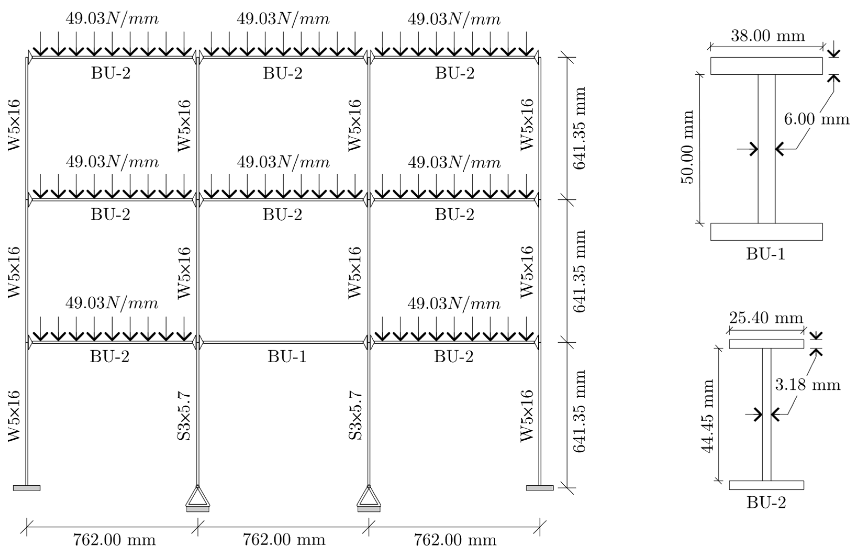
Figure 1. Properties of the reference structure for the maRTHS benchmark problem (reproduced from [48]).
Actuators 14 00525 g001
Figure 2. (a) Degree-of-freedom description for the model; (b) partition considered for the maRTHS benchmark problem (reproduced from [48]).
Actuators 14 00525 g002
Figure 3. (a) Boundary condition enforcement at the interface joint with two hydraulic actuators through a rigid coupler, (b) coupler kinematics (reproduced from [48]).
Actuators 14 00525 g003
Figure 4. Schematic for the v-maRTHS block diagram execution flow.
Actuators 14 00525 g004
Figure 5. Block diagram of the maRTHS benchmark control system (reproduced from [48]).
Actuators 14 00525 g005
Figure 6. Block diagram of the ADFC application to maRTHS benchmark problem.
Actuators 14 00525 g006
Figure 7. Block diagram of the ADFC execution flow.
Actuators 14 00525 g007
Figure 8. Tracking for v-maRTHS with plant uncertainty (Trial #1) under El Centro ground motion input (scaled to %40 PGA).
Actuators 14 00525 g008
Figure 9. Tracking for v-maRTHS with plant uncertainty (Trial #1) under Kobe ground motion input (scaled to %40 PGA).
Actuators 14 00525 g009
Figure 10. Tracking for v-maRTHS with plant uncertainty (Trial #1) under Morgan Hill ground motion input (scaled to %40 PGA).
Actuators 14 00525 g010
Figure 11. Time histories of the identified ADFC coefficients for Actuator 1 during the v-maRTHS (Trial #1).
Actuators 14 00525 g011
Figure 12. Synchronization subspace in the actuator coordinates for v-maRTHS (Trial #1): (a-1) El Centro—Actuator 1; (a-2) El Centro—Actuator 2; (b-1) Kobe—Actuator 1; (b-2) Kobe—Actuator 2; (c-1) Morgan Hill—Actuator 1; (c-2) Morgan Hill—Actuator 2.
Actuators 14 00525 g012
Figure 13. Synchronization subspace in the interface coordinates for v-maRTHS (Trial #1): (a-1) El Centro—Interface DOF 4; (a-2) El Centro—Interface DOF 28; (b-1) Kobe—Interface DOF 4; (b-2) Kobe—Interface DOF 28; (c-1) Morgan Hill—Interface DOF 4; (c-2) Morgan Hill—Interface DOF 28.
Actuators 14 00525 g013
Figure 14. v-maRTHS performance indicators derived from 1000 random simulations: (a) comparison of median and interquartile range for indicators J1–J10 for El Centro (PGA scaled by 40%) excitation using the LQG and ADFC; (b) for El Centro, Kobe, and Morgan Hill (PGA scaled by 40%) excitations considering only the ADFC.
Actuators 14 00525 g014
Figure 15. Histograms of performance indicators J2–J10 from 1000 v-maRTHSs using the ADFC under El Centro ground motion excitation (scaled to 40% PGA).
Actuators 14 00525 g015
Table 1. Natural frequencies and modal mass participation ratios.
ModeFrequencyEffective Modal Mass—TranslationEffective Modal Mass—Rotation
(Hz) U x (%) U x (%) R z (%) R z (%)
12.2981.0581.052.37 × 10−92.37 × 10⁻⁹
212.7416.6097.652.11 × 10−72.13 × 10⁻⁷
326.285.33 × 10−797.6561.7261.72
426.538.67 × 10−397.662.89 × 10−561.72
529.912.341002.42 × 10−561.72
Table 2. Parameter uncertainty definition for the transfer functions [48].
ComponentParameter Nominal Value  ( μ ) Standard Deviation  ( σ )
n u m 11 ( s ) d e n 11 ( s ) and n u m 21 ( s ) d e n 21 ( s ) Zero 1−753.9841.47
Zero 2−565.4831.10
Pole 1−16.651.00
Pole 2−251.3215.08
n u m 12 ( s ) d e n 12 ( s ) and n u m 22 ( s ) d e n 22 ( s ) Zero 1−18.850.57
Zero 2−31.420.94
Pole 1−21.990.66
Pole 2−116.24−3.49
n u m e s s d e n e s s Pole 1 and 2−314.16 ± 395.84i15.71 + 19.79i
Table 3. RTHS performance evaluation criteria overview (reproduced from [48]).
PerformanceIndexUnitCriterionEquation
Tracking ControlJ1msTracking time delay between desired and measured actuator displacements ( i = 1 , 2 ) J 1 , i = a r g   m a x r k = 1 N     x a , i [ k ] · x m , i [ k r ] × 1000 / f s
J2%Normalized tracking error. It represents the difference between target and measured actuator displacements ( i = 1 , 2 ) J 2 , i = k = 1 N   x m , i [ k ] x a , i [ k ] 2 k = 1 N   x a , i [ k ] 2 × 100
J3%Maximum peak tracking error between the instantaneous response of desired and measured actuator displacements ( i = 1 , 2 ) J 3 , i = m a x x m , i [ k ] x a , i [ k ] m a x ( x a , i k ) × 100
EstimationJ4msTime delay between target and estimated interface node displacements of the frame ( i = 1 , 2 ) J 4 , i = a r g   m a x r k = 1 N   x a , i [ k ] · x ^ m , i [ k r ] × 1000 / f s
J5%Normalized error of the difference between frame target displacements and estimated interface node displacements of the experimental frame ( i = 4 , 28 ) J 5 , i = k = 1 N   ψ ^ m ,   i [ k ] ψ ns , i [ k ] 2 k = 1 N   ψ ns , i [ k ] 2 × 100
J6%Maximum peak error between the instantaneous response of frame target displacement and estimated interface node displacements of the experimental frame ( i = 4 , 28 ) J 6 , i = m a x ( | ψ ^ m , i k ψ ns , i k | ) m a x ( ψ ns , i k ) × 100
Global RTHSJ7%Normalized error between reference and estimated measured response of the frame at the interface node ( i = 4 , 28 ) J 7 , i = k = 1 N   ( ψ ^ m , i [ k ] ψ i [ k ] ) 2 k = 1 N   ψ i [ k ] 2 × 100
J8%Normalized error between relative reference and relative numerical substructure response at upper stories ( i = 2 , 26 , 3 , 27 ) J 8 , i = k = 1   N   ψ ns , i [ k ] ψ i [ k ] 2 k = 1   N   ψ i [ k ] 2 × 100
J9%Maximum peak global displacement error between reference and estimated measured response of the frame at the interface node ( i = 4 , 28 ) J 9 , i = m a x | ψ ^ m , i k ψ i k | ) m a x ( ψ i k ) × 100
J10%Maximum peak global displacement error between relative reference and relative numerical substructure response at upper stories ( i = 2 , 26 , 3 , 27 ) J 10 , i = m a x ( | ψ ^ ns , i [ k ] ψ i [ k ] | ) m a x ( ψ i k ) × 100
Table 4. Performance assessment for the maRTHS and v-maRTHS.
PerformanceCriterionIndexExperimental maRTHS (with LQG)Virtual maRTHS for Nominal Plant (with LQG)Virtual maRTHS for Nominal Plant (with ADFC)
Tracking ControlTime delayJ1,1−13.72.00.98
J1,22.92.90.98
Normalized tracking errorJ2,123.84.83.90
J2,213.29.42.46
Max. peak tracking errorJ3,126.95.33.39
J3,213.710.32.92
EstimationTime delayJ4,11.91.90.98
J4,24.92.90.98
Normalized estimation errorJ5,48.16.71.69
J5,2827.817.82.59
Max. peak estimation errorJ6,48.27.42.36
J6,2828.618.83.88
Global RTHSNormalized RTHS errorJ7,412.210.69.18
J7,2826.216.87.13
Normalized RTHS error at upper levelsJ8,212.51.86.81
J8,2612.73.46.15
J8,312.42.16.46
J8,2712.53.06.20
Max. peak RTHS errorJ9,413.211.98.61
J9,2827.318.17.02
Max. peak RTHS error at upper levelsJ10,213.42.75.23
J10,2613.42.74.59
J10,312.81.84.77
J10,2713.22.44.61
Disclaimer/Publisher’s Note: The statements, opinions and data contained in all publications are solely those of the individual author(s) and contributor(s) and not of MDPI and/or the editor(s). MDPI and/or the editor(s) disclaim responsibility for any injury to people or property resulting from any ideas, methods, instructions or products referred to in the content.