Abstract
With the comprehensive digitalization and electrification of aircraft, electromechanical actuation systems (EAS) have been increasingly applied. However, EAS are affected by various nonlinear factors, such as friction and mechanical backlash, which can compromise system stability and control accuracy, thereby reducing the operational lifespan of the EAS. This study focuses on these two nonlinear factors and proposes a hybrid control approach to mitigate their effects. In the speed loop of the EAS, a Super-Twisting sliding mode controller combined with a generalized proportional–integral observer (GPIO) is designed, while in the position loop, a hybrid controller integrating a radial basis function (RBF) neural network with sliding mode control is implemented. Leveraging the advantages of numerical analysis in SIMULINK and dynamic simulation in ADAMS, a co-simulation framework is established to evaluate the hybrid control algorithm under nonlinear effects. Furthermore, a control test bench for the control surface transmission system is constructed to analyze the dynamic and static performance of the system under different control strategies and input commands. The experimental results show that, compared with the PID control, the hybrid control method reduces the steady-state error and vibration amplitude of the step response displacement by 51% and 75%, respectively, and decreases the amplitude of speed fluctuations by 75%. For the sinusoidal response, the displacement lag is reduced by 76%, and the amplitude of speed fluctuations is reduced by 50%.
1. Introduction
With the rapid development of more electric aircraft (MEA) and all electric aircraft (AEA) technologies, the application of electrification in the aviation sector is becoming increasingly widespread. Electromechanical actuation systems (EAS) are gradually emerging as a promising technology, indicating their potential to progressively replace traditional hydraulic actuation systems and serve as the next-generation flight control surface actuators [1,2,3].
The main components of the EAS include a permanent magnet synchronous motor (PMSM) and actuator elements such as lead screws, gears, reducers, and transmission mechanisms [4]. Due to manufacturing tolerances, internal motor parameter perturbations, and external disturbances, the EAS exhibits nonlinear behavior. Driven by a PMSM, the EAS connects to a lead screw, which in turn drives a pushrod rigidly fixed to the lead screw nut, producing linear motion. This configuration is simple and free of variable-speed stages, thereby minimizing energy loss and reducing the impact of transmission backlash on servo system performance. Typically, EAS employs a planetary roller screw mechanism (PRSM), which can withstand higher loads and offer longer service life compared to ordinary lead screws [5]. The multi-line contact in PRSM effectively enhances stiffness and impact resistance, making them well-suited for EAS applications. However, EAS still contains multiple nonlinear elements, such as friction, backlash, and elastic components. While applying preload can eliminate gaps in transmission mechanisms and increase system stiffness, it simultaneously increases the friction within the system [6,7,8].
The primary factors affecting the stability and control accuracy of the EAS are friction and backlash [9], which are the key nonlinearities that must be considered to achieve stable servo actuation. The presence of backlash can lead to response lag [10], increase the steady-state error, degrade dynamic performance, and even induce self-sustained oscillations in the electromechanical servo actuation system [11]. Current methods to mitigate the impact of backlash mainly involve mechanical preloading or gap elimination, but these approaches cannot completely remove the effects of backlash and also increase the structural complexity and cost of EAS. Friction disturbances can induce significant tracking errors, cause low-speed jitter or creep in rotary stages, and adversely affect the servo precision and low-speed stability of the system [12]. In practical engineering applications, new structural designs and industrial techniques are often employed to reduce friction effects in EAS; however, these methods cannot entirely eliminate the influence of friction [13,14]. Therefore, from a practical engineering perspective, it is essential to actively suppress the disturbances caused by both friction and backlash [15].
Researchers have conducted extensive studies on modeling, analysis, and compensation control of nonlinear factors in electromechanical servo systems. The authors of reference [16] carried out dynamic modeling and analysis of electromechanical actuators (EMA), including modeling of backlash, friction, and flexible components, and elaborated on a top-down parameterized design approach for EMA position control. The authors of reference [17] developed a system-level co-simulation model for flap actuation systems, comprehensively considering nonlinear factors in the EMA, impact dynamics of linkages with backlash joints, and rigid–flexible coupling characteristics. They experimentally validated the model under different command frequencies and loads, and further analyzed the effects of planetary roller screw contact stiffness and backlash, EMA fixed stiffness, the number of backlash joints, flexibility, and load on system performance. The authors of reference [18] proposed a composite sliding mode control method based on an improved extended state observer (MESO) to suppress adverse dynamic responses such as the flat-top effect and low-speed creep caused by friction nonlinearities in electromechanical actuators. The nonlinear MESO estimates friction dynamics, unmodeled disturbances, and external real-time load dynamics, and the method’s effectiveness and stability were verified through simulations. The authors of reference [19] addressed nonlinear characteristics and model uncertainties in EMAs commonly observed in microrobot manipulation, such as core saturation and magnetic hysteresis. They proposed a dual-loop robust control strategy, combining outer-loop sliding mode control with an inner-loop disturbance observer to achieve real-time compensation of composite disturbances, thereby enhancing system stability and precision. The authors of reference [20] investigated nonlinear transmission effects in electromechanical flight control systems and proposed actuator command compensation methods. They established a simulation model for analyzing nonlinear transmission effects and designed corresponding compensation algorithms to mitigate their impact. The authors of reference [21] studied nonlinear factors such as backlash and friction in the mechanical transmission of flap actuators and, based on characteristic analysis, developed a comprehensive simulation model. They constructed a torque–current compensation model using a simplified backlash dead-zone model and the LuGre friction model, and applied feedforward compensation to control and adjust the q-axis current, thereby improving the system’s position control accuracy.
Currently, most research on nonlinear compensation in EAS focuses on targeted elimination of specific nonlinearities. However, since multiple nonlinear elements coexist in EAS, it is particularly necessary to address these influencing factors in a unified manner. Therefore, the development of hybrid control algorithms for EAS, aimed at reducing distortions caused by the combined effects of multiple nonlinearities [22,23], has become a key research focus. Different control strategies possess their own advantages and limitations. By integrating multiple control algorithms, complementary strengths can be leveraged to achieve efficient and precise actuation of electromechanical servo systems.
The innovative contributions of our work can be summarized as follows:
- (1)
- Previous studies on EAS typically consider the control system and the mechanical transmission separately, focusing on one aspect at a time. In this work, we investigate the coupled interactions between drive control and mechanical nonlinearities. In addition, both friction and backlash are considered simultaneously, revealing their combined effect on system performance. This integrated approach provides a more comprehensive understanding of EAS dynamics and offers guidance for improving tracking accuracy under realistic mechanical conditions.
- (2)
- A hybrid control strategy is proposed to suppress the effects of nonlinear factors in electromechanical actuation systems. Hybrid control models are designed separately for the velocity loop and the position loop. In the velocity loop, a combination of super-twisting sliding mode control and a GPIO is employed to mitigate disturbances caused by nonlinearities while reducing the chattering inherent in sliding mode control. In the position loop, an RBF neural network is integrated with sliding mode control, where the RBF neural network approximates the nonlinear terms in the sliding mode controller, ensuring the stable operation of the electromechanical actuation system.
- (3)
- Considering that a single simulation platform cannot accurately replicate the actual operating conditions of EAS, this study employs a co-simulation platform combining SIMULINK and ADAMS 2019. This approach allows both kinematic analysis of the EAS and the design of nonlinear system controllers in MATLAB/SIMULINK 2021b. By building the control surface transmission system model in ADAMS and incorporating appropriate constraints and contact forces, the effects of backlash and friction on transmission accuracy can be effectively simulated. Meanwhile, the hybrid controller is implemented in SIMULINK to provide improved compensation for nonlinear factors in the EAS.
Based on an analysis of the overall structure of EAS, this study establishes mathematical models for friction and backlash. In the speed loop of the EAS, an improved Super-Twisting sliding mode controller is designed in combination with GPIO. In the position loop, a hybrid controller integrating RBF neural network with sliding mode control is developed. By leveraging the advantages of SIMULINK numerical analysis and ADAMS dynamic simulation, a co-simulation of the hybrid control algorithm under the influence of nonlinear factors is conducted. Experiments are conducted on a test platform, and the results are analyzed. Finally, the paper summarizes the work conducted and proposes areas for improvement.
2. Materials and Methods
2.1. Mathematical Model of EAS
2.1.1. Mathematical Model of PMSM
The mathematical model of PMSM consists of four equations: the voltage equation, the flux linkage equation, the torque equation, and the motion equation. Since the PMSM does not contain rotor windings, both the voltage and flux linkage equations are formulated only for the stator side.
The PMSM is a nonlinear, time-varying, and complex control system. To simplify the computational process, the coordinate transformation theory is commonly employed to decouple the system variables. Specifically, the mathematical model of the PMSM in the three-phase static coordinate system (ABC) is transformed into the two-phase rotating coordinate system (dq), and the corresponding mathematical equations are obtained as follows:
- Stator voltage equation
The stator voltage equation in dq coordinate system is expressed as:
where ud and uq denote the stator voltage components in dq coordinate system, respectively; id and iq represent the stator current components in dq coordinate system, respectively; ψd and ψq are the flux linkage components in dq coordinate system; ωe is the electrical angular velocity of the rotor.
- 2.
- Stator flux linkage equation
The stator flux linkage equation in dq coordinate system is expressed as:
where ψf is the flux linkage produced by the permanent magnet; Ld and Lq are the direct-axis and quadrature-axis inductances in the dq coordinate system, respectively.
- 3.
- Electromagnetic torque equation
The electromagnetic torque equation in dq coordinate system is expressed as:
where Te is the electromagnetic torque of PMSM; np is the pole pairs of the rotor.
- 4.
- Mechanical motion equation
The mechanical motion equation in dq coordinate system is expressed as:
where ωm is the rotor mechanical angular velocity; J is the moment of inertia; B is the damping coefficient; Te is the electromagnetic torque; TL is the load torque; and Tf is the friction torque.
2.1.2. Mathematical Model of the Gearbox
The gearbox is modeled using a typical cylindrical gear reducer as an example, and its transmission schematic is shown in Figure 1.
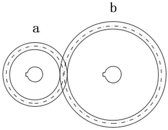
Figure 1.
Schematic Diagram of the Cylindrical Gear Reducer.
In Figure 1, the first-stage gear a transmits the input torque to the second-stage gear b, which can amplify the torque to a certain extent. The amplification ratio depends on the number of teeth of the gears.
Assuming that gear a has Z1 teeth, gear b has Z2 teeth, the gear ratio is i, and the transmission efficiency is η, the following relationships can be obtained:
The relationship between the input torque T1 and the output torque T2 is given by:
The relationship between the input angular velocity ω1 and output angular velocity ω2 is given by:
2.1.3. Mathematical Model of the Planetary Roller Screw
The planetary roller screw mechanism is a device that can convert rotational motion at the input into linear motion at the output. It primarily consists of three components: the screw, the rollers, and the nut. The working principle is illustrated in Figure 2.
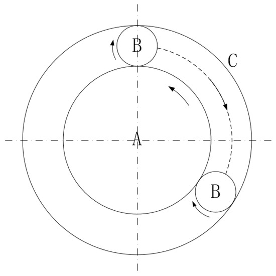
Figure 2.
Working Principle of the Planetary Roller Screw.
In Figure 2, A represents the screw, B represents the rollers, and C represents the outer nut. For each complete rotation of the screw, the rollers and the nut undergo an axial displacement equal to one lead of the screw. The lead refers to the axial distance between corresponding points on two adjacent threads along the same helix. Assuming that the screw has ns starts and a pitch of p, the lead s can be expressed as follows:
Given a rotation angle θs of the screw, the linear displacement x of the nut can be expressed as:
Combining Equations (8) and (9), the following relationship can be obtained:
Let the angular velocity of the screw be ωs. Then, the following relationship can be obtained:
By combining Equations (10) and (11), the displacement equation of the screw can be obtained as follows:
By differentiating both sides of Equation (12) with respect to time, the velocity equation of the screw can be obtained as follows:
Let the input torque applied to the screw be T, the output force of the nut be F, and the transmission efficiency be η. According to the principle of energy conservation, the following relationship can be obtained:
By combining Equations (13) and (14), the output force equation of the screw can be obtained as follows:
2.1.4. Mathematical Model of Nonlinear Factors
This study focuses on the analysis of friction disturbances and backlash disturbances in the EAS, and an appropriate mathematical model of nonlinear factors is established based on the actual conditions of the EAS.
The friction in the EAS primarily includes the internal friction of the PRSM, the friction in the motor shaft, the friction between the output rod and the rocker, and the friction between the rocker and the bearing housing. The LuGre friction model is established as follows:
where z is the average bristle deformation in the LuGre model, vs is the Stribeck velocity, v is the relative velocity of the contact surfaces, σ0 is the average stiffness of the bristles at the contact interface, σ1 is the damping coefficient of bristle deformation, a is the viscous friction coefficient, Fc is the coulomb friction force, Fs is the static friction force, and Ff is the total friction force.
The backlash in the EAS mainly includes the axial clearance between the screw and the nut, the tooth backlash in the gear transmission, the inherent clearance of the joint bearings, and the clearances between the output rod and the rocker and between the rocker and the bearing housing. The model established in this study primarily considers the total backlash of the EAS.
When the feedback signals of the EAS are the force and velocity at the EAS connection, the backlash is modeled using a dead-zone model. The mathematical expression of the dead-zone model for the backlash is given by:
where T is the backlash; K is a constant related to the stiffness; Δx is the relative displacement between the two components, and 2B is the width of the dead zone.
When the feedback signal of the EAS is displacement, the backlash is modeled using a hysteresis model:
where x0 is the output of the backlash model; xi is the input displacement of the system; l is a constant related to the backlash; Δx is the relative displacement between the two components.
2.2. Hybrid Control Strategy Design for the EAS
2.2.1. Design of Super-Twisting Controller for the Speed Loop
The traditional sliding mode controller has attracted considerable attention due to its insensitivity to disturbance parameters and fast response characteristics. However, its inherent chattering problem remains a critical issue that limits its widespread application. To address this issue, the Super-Twisting sliding mode controller (ST-SMC) has emerged, which has gained widespread popularity due to its simple structure and excellent tracking performance [24,25,26]. The integrator in the Super-Twisting controller plays a crucial role in the control process, as it helps smooth the discontinuous signals, thereby achieving higher tracking accuracy and mitigating the chattering phenomenon. Next, the Super-Twisting controller for the EAS will be designed in detail. The mechanical motion equation of the PMSM can be expressed as:
Let
where iq* is the q-axis reference current, and d0(t) is the total disturbance of the system. Then, Equation (19) can be simplified as:
Let , , , , and Equation (22) can be rewritten as:
Based on the theoretical foundation of the Super-Twisting algorithm, the Super-Twisting sliding mode controller is constructed as follows:
where . The control signal u can enter the neighborhood within a finite time, and the velocity error x1 will converge to zero in finite time.
The convergence of the Super-Twisting control method is briefly proved as follows:
First, it is proved that the control signal u can converge to the neighborhood . When , differentiating u with respect to time, the following equation is obtained:
Since b is a positive constant and d(t) is a bounded disturbance, it can be obtained that:
By combining Equation (23), the following can be obtained:
It can be further obtained that:
The convergence of the control input u to the neighborhood is thus proved.
Next, it is proved that the system is convergent within the neighborhood . When , differentiating the control equation yields:
Since the disturbance d(t) is bounded, holds at least locally. As D is a positive constant, Equation (29) can be written as:
As shown in Figure 3, within the range of , the trajectory curves are constrained by the and axis.
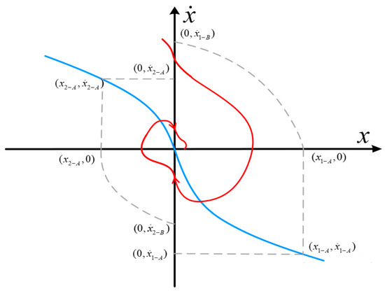
Figure 3.
Phase-plane Curves of the Super-Twisting Control System.
Let the intersection point of the curve and the axis be denoted as . By performing two successive integrations of the curve , it can be obtained that:
Considering the curve within the maximum range, let , and the equation can be expressed as:
Letting , it can be obtained that:
As shown in Figure 3, is constrained by in the region . As clearly shown in Figure 3, when , the control system is convergent. According to Equation (33), the convergence condition can be rewritten as:
When the parameter satisfies the condition
the convergence condition is satisfied. When the curve within the maximum range satisfies the convergence condition, the condition remains valid as the trajectory continues to evolve. Therefore, the system can converge within a finite time.
Although the Super-Twisting sliding mode algorithm is inherently a continuous method, the presence of discretized variables and the sign function still leads to noticeable chattering in practical applications [27,28,29]. While the amplitude of chattering in the Super-Twisting algorithm may be relatively small, for high-precision EAS, the chattering of the control signal can excite high-frequency system dynamics, thereby degrading leveling accuracy and reducing tracking performance [30,31,32,33].
Therefore, in this study, a novel boundary-layer Super-Twisting sliding mode control method is adopted, in which the sign function is replaced by a saturation function to further eliminate chattering [34]. Its stability is proven using a Lyapunov function. The specific form of the improved Super-Twisting sliding mode controller is as follows:
where is the exponential factor with , and adjusting the value of can improve control accuracy; represents the boundary layer thickness, and . The parameters and are the gains of the super-twisting sliding mode controller with . The stability of the improved system is proved as follows.
When , the convergence of the improved Super-Twisting controller is equivalent to that of the standard Super-Twisting controller. At this point, when and satisfy
the system is stable, where D represents the upper bound of the disturbance.
When , the system equation can be rewritten as , where .
The following variables are defined:
Assume , where . This disturbance is related to the sliding variable, with d2 being a constant and its derivative equal to zero. Then, the improved controller can be rewritten as:
where .
For Equation (39), if and satisfy the following condition, then , i.e.,
and Equation (39) is convergent. The proof is detailed as follows. First, the Lyapunov function is defined as follows:
By differentiating with respect to time, it can be obtained that:
where .
By differentiating V with respect to time, it can be obtained that:
When and satisfy the condition, T is a positive definite matrix. Therefore, for , the system stability is established.
The parameter of the controller that need to be tuned are , , and . The selection of these parameters is based on both theoretical derivation and tuning experience. First, the theoretical lower bounds of the controller gains and are determined according to the upper bound of the system disturbance D in Equation (37). Increasing accelerates system convergence and improves accuracy, but may increase control signal chattering. Increasing enhances disturbance rejection capability, but also increases the control effort [35].
The parameter is the exponential factor, generally chosen between 0.5 and 0.8. A smaller value results in smoother but slower convergence, while a larger value leads to faster convergence but may cause chattering.
The parameter is the boundary layer thickness. Increasing smooths the system control and reduces chattering, but decreases accuracy; decreasing improves accuracy but may lead to noticeable chattering.
Therefore, initial values of these parameters are set, and then fine-tuned through multiple simulations to balance convergence speed, control smoothness, and steady-state accuracy. In general, if the system steady-state error is too large, should be decreased or increased; if chattering is evident, should be increased or decreased.
2.2.2. Design of Generalized Proportional-Integral Observer for the Speed Loop
In general, certain external disturbances may adversely affect the performance of the EAS, such as wind forces acting on the system load, as well as friction and backlash present between internal components. In order to achieve improved velocity tracking performance and enhanced rejection of higher-order disturbances, a generalized proportional-integral observer (GPIO) is employed, forming a composite control strategy.
The GPIO is designed below, considering the following control system:
where and are the state variables, is the input, is the output, and represents the total disturbance.
A higher-order extension of Equation (45) is performed, taking the following form:
where is the new extended state variable, and is the derivative of .
As an example of a first-order extension, the observer for Equation (45) is designed as follows:
By defining and combining Equations (45) and (46), it can be obtained that:
where represents the second derivative of . The corresponding system error equation can be expressed as:
After performing the first-order extension, there always exists an equation , and by appropriately selecting , the system disturbance can be accurately observed.
Next, the specific design of the GPIO is presented. For the control system shown in Equation (23), the GPIO is designed as follows:
where z1 denotes the estimated system velocity, while z2 and z3 correspond to the total disturbance d(t) and its derivative, respectively.
Combining the improved sliding mode controller designed in Equation (36), the composite controller, consisting of the improved Super-Twisting sliding mode controller and the GPIO, is designed as follows:
2.2.3. Design of Hybrid Controller for the Position Loop
Traditional sliding mode controllers require relatively large gains to mitigate the effects of nonlinearities in the control system; however, such large gains can induce chattering. In this study, a radial basis function (RBF) neural network is employed to estimate the parameters of the sliding mode controller, thereby reducing the impact of nonlinearities. This allows the controller to be designed with smaller gains, which further diminishes the chattering caused by the sliding mode gain terms [36,37,38]. Additionally, the neural network can accurately approximate the unknown components in nonlinear control systems, thereby enhancing control performance and mitigating the effects of nonlinear factors such as friction and backlash.
By combining Equations (4), (7) and (12), the motion equation of the EAS can be expressed as:
After further simplification, it can be expressed as:
By setting , it can be obtained that:
Considering the system disturbances and replacing with , by setting , it can be obtained that:
The sliding surface is designed as
where e denotes the position tracking error, xd is the reference displacement command, and x represents the actual displacement.
By applying the constant-speed reaching law , the derivative of the sliding surface s is obtained as:
Then, the corresponding control law is given by:
Since the nonlinear function is unknown and time-varying, the RBF neural network is employed to approximate . The RBF neural network algorithm is given as follows:
where denotes the input vector, is the center vector, represents the output of the Gaussian function, corresponds to the ideal network weights, and denotes the approximation error, which has an upper bound.
The network input is chosen as , and the RBF network output is , with representing the Gaussian function. By replacing in the control law u with , the control law can be expressed as:
The stability of the control system is proved as follows. By substituting Equation (60) into Equation (56), it can be obtained that:
where .
The Lyapunov function is defined as:
By combining Equations (60) and (61), the derivative of the Lyapunov function is obtained as:
To ensure system stability, the adaptive law is defined as:
Then
Since the approximation error and the switching gain are both bounded, by choosing x < 1x < 1x < 1, it can be obtained that:
Since , when , . According to LaSalle’s invariance principle, the closed-loop system is asymptotically stable.
In the controller, the number of RBF nodes is chosen based on the system state dimension and the complexity of the disturbances, typically ranging from 5 to 20. Too few nodes result in poor approximation capability, while too many nodes increase computational cost.
The RBF centers should uniformly cover the state space or the critical intervals of the reference trajectory; in this study, an evenly spaced distribution is used. The RBF width controls the local response and is usually set to one-fourth of the state range, ensuring coverage of the state space without excessive overlap. The initial values of the weight vector are generally set to zero or small random values. Ultimately, the values of these parameters are adjusted by observing the convergence, steady-state error, and control chattering in the simulation results, in order to achieve a balance between accuracy and stability.
2.3. Co-Simulation Analysis of the Hybrid Control of the EAS
Based on the nonlinear mathematical model of the EAS and the proposed hybrid control algorithms, SIMULINK and ADAMS models were developed, and simulation analyses were conducted.
2.3.1. SIMULINK Simulation of the Speed Loop
The built-in three-phase PMSM simulation module in SIMULINK was employed. The stator phase resistance was set to , the d-axis and q-axis inductances were set to and , respectively, the leakage flux coefficient was , the rotor inertia was , the viscous damping coefficient was , the number of pole pairs was 4, and the DC bus voltage was .
Based on the previously developed Super-Twisting sliding mode controller and GPIO model, the control system was implemented in SIMULINK.
Figure 4 illustrates the SIMULINK model of the dual-loop composite control system, which accounts for both friction and backlash.
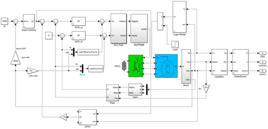
Figure 4.
Simulation Model of the Composite Controller for the Speed Loop.
The rated speed was set to 1000 rpm, and the simulation time was 2 s. The solver was configured as ode23tb. A step reference input was applied, and a 10 N·m load was suddenly added at 0.4 s. The speed loop performance was compared among the PI controller, the sliding mode controller, the Super-Twisting sliding mode controller, and the hybrid controller composed of the Super-Twisting sliding mode controller combined with the GPIO. The simulation results are presented in Figure 5.
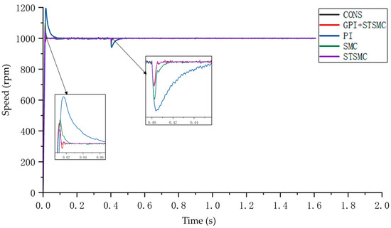
Figure 5.
Comparison of the Control Performance of Different Algorithms under Step Reference Input.
As shown in the figure, compared with the PI controller, the sliding mode controller exhibits a smaller overshoot and significantly improved disturbance rejection. Among the sliding mode-based methods, the hybrid control approach combining the Super-Twisting sliding mode controller with the GPIO demonstrates superior dynamic performance and disturbance rejection capability.
A sinusoidal speed reference with an amplitude of 1000 rpm and a frequency of 0.318 Hz was applied, with a simulation time of 5 s. A sudden load of 10 N·m was applied at 0.4 s. The simulation results are shown in Figure 6. Under control, the speed temporarily decreases at 0.4 s, but the speed error is eliminated within 0.02 s, and the system continues to follow the reference. The system employing the hybrid controller exhibits smaller speed errors, whereas the PI-controlled system requires 0.05 s to resume tracking. Notably, the PI controller shows significant chattering at 1.1 s and 1.58 s, while the sliding mode controllers exhibit no chattering. Overall, the hybrid control approach combining the Super-Twisting sliding mode controller with the GPIO demonstrates stronger disturbance rejection under a sinusoidal speed reference.
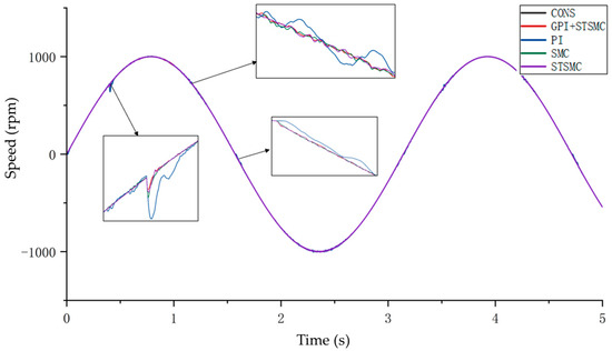
Figure 6.
Comparison of the Control Performance of Different Algorithms under Sinusoidal Reference Input.
2.3.2. SIMULINK Simulation of the Position Loop
Based on the previously developed Super-Twisting sliding mode controller, GPIO model, and RBF + SMC hybrid controller, the control system was implemented in SIMULINK. The parameters of the permanent magnet synchronous motor are the same as those presented in the previous subsection.
Figure 7 illustrates the SIMULINK model of the three-loop composite control system, which accounts for both friction and backlash.
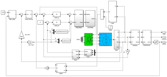
Figure 7.
Simulation Model of the Composite Controller for the Position Loop.
The simulation time was set to 5 s, and the solver was configured as ode23tb. A displacement reference of 120 mm was applied, with a backlash width of 0.1 mm. A sudden load of 10 N·m was applied at 3 s. The position loop performance was compared among the PI controller, the fuzzy PI controller, the sliding mode controller, and the hybrid controller composed of the RBF and sliding mode controller.
As shown in Figure 8, although the displacement of the electromechanical servo system under all four control algorithms rapidly reaches the specified target position, the presence of friction and backlash results in a dead-zone effect. Under PI control, the system displacement remains at 0 mm for approximately 0–0.018 s, whereas under fuzzy PI, SMC, and RBF + SMC control, the dead-zone durations are approximately 0.009 s, 0.013 s, and 0.007 s, respectively.
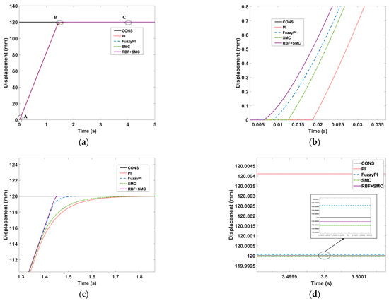
Figure 8.
Comparison of the Control Performance of Different Algorithms under Step Reference Input: (a) Simulation Results of the Position Response under Step Reference; (b) Magnified View of the Dead-Zone Displacement at Point A; (c) Magnified View of the Rise Time at Point B; (d) Magnified View of the Steady-State Error at Point C.
Furthermore, under RBF + SMC control, the system displacement reaches the target position and stabilizes at around 1.45 s, while under SMC, fuzzy PI, and PI control, the system requires approximately 1.75 s, 1.55 s, and 1.84 s, respectively, to achieve the target position. The steady-state errors under RBF + SMC, SMC, and fuzzy PI control are extremely small, at 2 × 10⁻⁵ mm, 4 × 10⁻⁵ mm, and 6 × 10⁻⁵ mm, respectively, whereas the steady-state error under PI control is comparatively larger, approximately 4 × 10⁻² mm.
Therefore, compared with PI, fuzzy PI, and SMC control, the RBF + SMC hybrid controller demonstrates significantly superior capability in suppressing nonlinear effects such as backlash and friction.
2.3.3. Construction of the ADAMS Dynamic Model
A simplified EAS transmission model was created in SOLIDWORKS and subsequently imported into ADAMS to develop a dynamic simulation model. As shown in Figure 9, the EAS transmission mechanism primarily consists of bearing housings, actuating rods, auxiliary linkages, auxiliary rocker arms, rocker arms, and inertia discs. During rapid reciprocating motion of the EAS, nonlinear effects such as backlash and friction occur between the actuating rod and the auxiliary rocker arm (hinge 1), the auxiliary rocker arm and the auxiliary linkage (hinge 2), the auxiliary rocker arm and bearing housing 3 (hinge 3), and between the auxiliary linkage and the rocker arm (hinge 4).
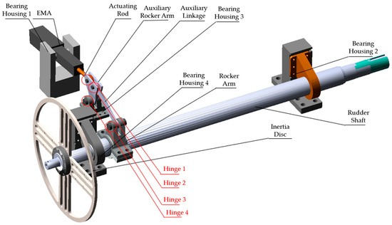
Figure 9.
EAS Transmission Mechanism Model.
In order to simulate the influence of different backlash on the EAS, it is necessary to parameterize the radius of the hinge bearings. The specific procedure is as follows: a new design variable is created under the “Design Exploration” module, and during the modeling of the pin shaft, the radius is defined as the variable name. In this way, the radius of the pin shaft can be adjusted by modifying the parameter, thereby enabling the simulation of different levels of hinge backlash.
During the rapid reciprocating motion of the EAS, nonlinear factors such as backlash and friction occur at the joints, including the actuator rod and the auxiliary rocker (hinge 1), the auxiliary rocker and the auxiliary link (hinge 2), the auxiliary rocker and the bearing seat (hinge 3), and the auxiliary link and the rocker (hinge 4). These nonlinearities degrade the tracking accuracy of the EAS, induce torque ripple, and consequently reduce its service life.
After the EAS modeling is completed, motion pairs and contact forces are added according to the relative positions among the assemblies and the overall motion characteristics of the transmission mechanism. After introducing all the constraints, the model mainly consists of 15 fixed joints, 3 revolute joints, and 1 prismatic joint. The detailed description of the relationships between the components is as follows:
- Fixed joint
The fixed joints are primarily established between the bearing seat and the ground, the pin and pin shaft, the rocker arm and rudder shaft, and between the rudder shaft and the inertia disk, in order to ensure that the relative positions of the corresponding components remain unchanged. The bearing seat anchors the entire system to the ground, while the rocker arm is connected to the rudder shaft to achieve the conversion from linear motion to rotary motion.
- 2.
- Revolute joint
Revolute joints are established between the EMA and bearing housing 1, the rudder shaft and bearing housing 2, and between the rudder shaft and bearing housing 3. Since the backlash and friction at these locations are considered to be ideal, the connections can be represented as ideal revolute joints.
- 3.
- Prismatic joint
A prismatic joint is added between the EMA and the actuator rod to simulate the linear motion of the EMA.
This study mainly considers the effects of hinge backlash and friction on the EAS. Based on the relationships among the components, contact forces are added only at hinges 1, 2, 3, and 4. The contact force model is established using the Impact method, with contact forces applied to the connections between the shaft and the link, the shaft and the auxiliary rocker, the rocker and the link, bearing housing 3 and the auxiliary rocker, and the shaft and the bearing housing.
The contact force model in ADAMS is decomposed into two components: normal force and friction force. The normal force is calculated using the Impact method, while the friction force is calculated using the Coulomb method. The calculation model for the contact normal force is based on Hertzian contact theory, employing the nonlinear equivalent spring-damper model provided by the Impact function. The general expression of the contact force is the superposition of elastic force and damping force. The elastic force arises from the compression deformation and mutual penetration between the two components, while the damping force results from their relative motion. The specific calculation formula is as follows:
where is the stiffness, is the force exponent, is the penetration depth, is the damping coefficient, and is the normal relative velocity at the contact point.
The friction force in ADAMS is based on a nonlinear friction model, where the transition between static and kinetic friction depends on the relative sliding velocity between contacting bodies. is the transition velocity for static friction, is the transition velocity for kinetic friction, is the maximum static friction coefficient, and is the kinetic friction coefficient, satisfying and . When the relative sliding velocity lies within , the corresponding friction coefficient is within . As the absolute value of the relative sliding velocity increases from to , the friction transitions from static to kinetic. When the absolute value of the relative sliding velocity exceeds , the components experience kinetic friction, and the friction coefficient remains at .
The detailed parameter settings are listed in Table 1:

Table 1.
Contact Force Parameters.
The ADAMS model, after adding all the joints and contact forces, is shown in Figure 10.
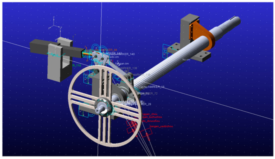
Figure 10.
ADAMS Dynamic Simulation Model.
2.3.4. Co-Simulation Based on SIMULINK and ADAMS
After completing the construction of the EAS control system and the mechanical dynamic model, the linear velocity of the EMA obtained from SIMULINK is transmitted to the ADAMS mechanical dynamics simulation. The mechanical transmission module converts this velocity information into a velocity-driven input for the EMA model in ADAMS. Subsequently, the angular displacement and EMA load are fed back to SIMULINK, where the difference between the target and actual angles is processed by the controller to update the motor input. This control action modifies the velocity, thereby affecting the displacement, enabling dynamic data exchange between the two simulation models.
After configuring the inputs and outputs in ADAMS, the model is established and constraints are applied. A velocity driver is added to the translational joint along the direction of the actuator rod. Data exchange between SIMULINK and ADAMS is realized through the settings of element variables, velocity drivers, angular displacement element variables, and load force element variables.
The transmission model is exported, and through model interaction and parameter configuration, the resulting model block diagram is shown in Figure 11. By adjusting the subsystem parameters, the co-simulation is ultimately realized, and its corresponding model is presented in Figure 12.
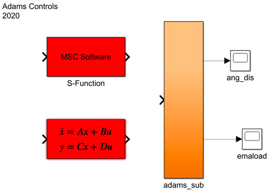
Figure 11.
Co-simulation Interface Module.
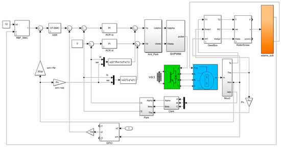
Figure 12.
EAS Co-simulation Model.
Simulation time was set to 5 s with the solver configured as ode23tb, and a step angle command of 10 degree was applied. The hinge backlash was set to 0.01 mm. The co-simulation results are shown in Figure 13 and Figure 14. Due to the effects of backlash and friction, the control system exhibits oscillations around the target value after reaching it. The position-loop composite controller proposed in this study significantly suppresses these oscillations, demonstrating superior attenuation of nonlinear effects compared to the PID controller.
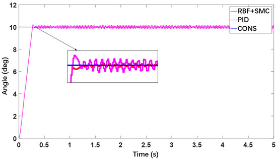
Figure 13.
Angle Response Simulation under Step Command Input.
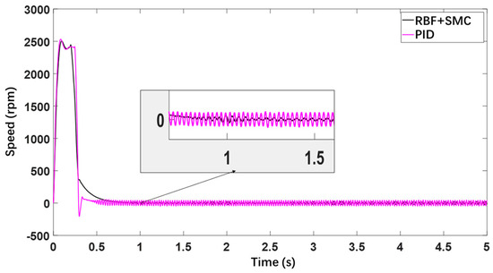
Figure 14.
Speed Response Simulation under Step Command Input.
For the speed loop, a comparison between PID controller and Super-Twisting + GPIO composite controller is shown in Figure 14. Around 0.3 s, the PID controller exhibits noticeable overshoot, and the system shows significant oscillations in velocity after the angle reaches its target. The proposed composite controller effectively reduces velocity fluctuations and significantly diminishes both the frequency and amplitude of oscillations. During steady-speed operation, the oscillations under the composite controller are clearly smaller than those under the PID controller, indicating that the speed-loop composite controller has a superior ability to suppress nonlinear effects.
3. Results
The EMA test bench mainly consists of two parts: the hardware structure and the software system. A photograph of the test bench is shown in Figure 15. The primary components of the test bench include the EMA, auxiliary rocker arm, rudder shaft, and inertia disk, among other mechanisms.
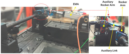
Figure 15.
Photograph of the Control Surface Transmission System Test Bench.
The test bench’s upper computer is a PC application implemented with LABVIEW software 2019, responsible for visualization and human–machine interaction. It communicates with the lower computer via an Ethernet connection, sending control commands and receiving feedback data. The lower computer acts as an intermediary in the system, exchanging information with the upper computer. It receives commands from the upper computer and converts them into digital control signals, which are then sent to the drivers. Simultaneously, it receives digital signals from the sensors, converts them, and feeds them back to the upper computer.
The tested EMA is the Shanghai Jiwang SEA805 model, featuring a lead screw pitch of 8 mm and an effective stroke of 250 mm. The actuator provides a rated thrust of 104 kN and an effective output force of 50 kN, with a rated speed of 240 mm/s. The motor is rated at 31 kW, driven at a current of 58 A. The motor driver employed is the Kollmorgen S772, with a rated voltage of 400 VAC. The loading system employed an Italian LAFERT B132I servo motor, with a rated voltage of 400 VAC, a rated speed of 2000 rpm, a rated power of 19.8 kW, and a rated torque of 94.5 N·m. The motor driver selected is the Kollmorgen S748, which provides a rated voltage of 400 VAC and a rated current of 48 A.
At the loading output end, a Beijing AVIC torque sensor was employed, while the electromechanical servo actuator’s output end was equipped with a Beijing AVIC tension–compression sensor. The displacement at the loading output was measured using a HEIDENHAIN incremental rotary encoder from Germany, and the displacement at the actuator output was measured using an FLTECH series magnetostrictive linear displacement sensor from Shanghai Fenglin. The measurement specifications of these sensors are as follows.
- Beijing AVIC torque sensor
The torque ranges of this sensor are 3000 N·m for the large range and 500 N·m for the small range, with an accuracy of 0.2% FS.
- 2.
- Beijing AVIC tension–compression sensor
The accuracy of this sensor is 0.2% FS, with an output range of 0–50 kN and an output voltage of ±5 V.
- 3.
- HEIDENHAIN incremental rotary encoder
The accuracy of this sensor is ±60″, with incremental TTL signals.
- 4.
- FLTECH series magnetostrictive linear displacement sensor
This sensor is a non-contact type with a resolution of 0.0015% (16-bit D/A), nonlinearity less than ±0.01%, and an output signal of 4–20 mA.
The corresponding angular velocity and angular acceleration values were further calculated in LABVIEW.
3.1. Step Response Test of the Hybrid Control Algorithm
First, a step response test was conducted using a speed-loop PID controller combined with a position-loop PID controller. The test duration was set to 10 s, with a commanded angle of 4.72 deg applied. The PID controller test results are shown in Figure 16. The actuator angle reached the target value around 1 s but exhibited high-frequency oscillations near the target. The oscillation amplitude ranged approximately ±0.2 deg.
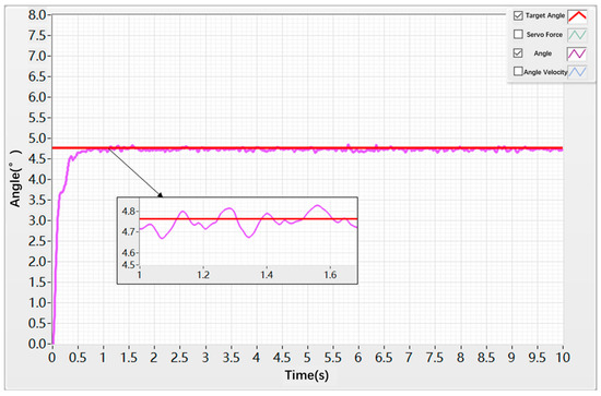
Figure 16.
Angular Step Response under PID Control.
The simulation results of the angular velocity under the PID controller are shown in Figure 17. The peak angular velocity of the rudder shaft reached 42 deg/s, with noticeable oscillations occurring between 0 s and 0.8 s, reaching a maximum amplitude of 8 deg/s. Additional fluctuations with an amplitude of ±1.3 deg appeared around 1.75 s and 2.35 s.
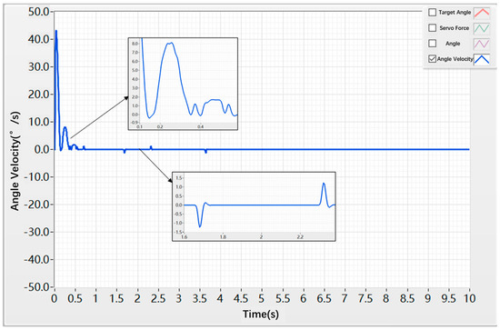
Figure 17.
Angular Velocity Step Response under PID Control.
Next, a step response test was conducted using the hybrid control strategy, combining the velocity-loop hybrid controller with the position-loop hybrid controller. The test duration was set to 10 s, with a given angular command of 4.72 deg. As shown in Figure 18, the angular position reached the target value at approximately 0.7 s, exhibiting only minor oscillations around the target with an amplitude of ±0.05 deg and a low oscillation frequency.
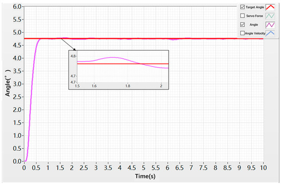
Figure 18.
Angular Step Response under Hybrid Control.
The corresponding angular velocity response under the hybrid controller is presented in Figure 19, where the peak angular velocity of the rudder shaft reached 27°/s. No oscillations were observed between 0.3 s and 0.9 s. Around 0.9 s, the angular velocity reached the target value, and minor oscillations occurred around 1.75 s and 2.35 s, with a fluctuation amplitude of only ±0.2 deg.
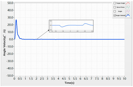
Figure 19.
Angular Velocity Step Response under Hybrid Control.
As shown in Figure 16, Figure 17, Figure 18 and Figure 19, due to the inherent backlash and friction in the control surface actuation system, the step response displacement exhibits certain oscillations under step commands, making it impossible to accurately and stably track the command signal. Meanwhile, the step response velocity shows relatively large peak values. This is because the mechanical components in the actual control surface actuation system involve more complex friction and backlash, as well as the flexibility of the mechanical parts, which also induces oscillations in the control surface deflection speed.
Table 2, Table 3, Table 4 and Table 5 present a comparison of time-domain dynamic performance metrics between the conventional PID algorithm and the hybrid control algorithm. The data indicate that the hybrid algorithm can effectively suppress the disturbances caused by nonlinear factors in the actuator system, enabling smoother system operation while achieving superior dynamic performance.

Table 2.
Time-domain Performance Indicators of Angular Response for the Two Control Algorithms.

Table 3.
Dynamic metrics of Angular Response for the Two Control Algorithms.

Table 4.
Time-domain Performance Indicators of Angular Velocity Response for the Two Control Algorithms.

Table 5.
Dynamic metrics of Angular Velocity Response for the Two Control Algorithms.
3.2. Sinusoidal Response Test of the Hybrid Control Algorithm
First, a sinusoidal test was conducted using a PID controller for both the speed loop and the position loop. The reference input was a sinusoidal angle command with an amplitude of 19 deg and a frequency of 0.05 Hz, while the test duration was set to 25 s. The experimental results, as shown in Figure 20, indicate that the rudder shaft initially moved in the opposite direction at approximately 0 s, and began to follow the reference direction at around 0.02 s. Throughout the test, a steady error of approximately 1.3 deg was observed between the actual angle and the reference command, accompanied by oscillations in displacement.
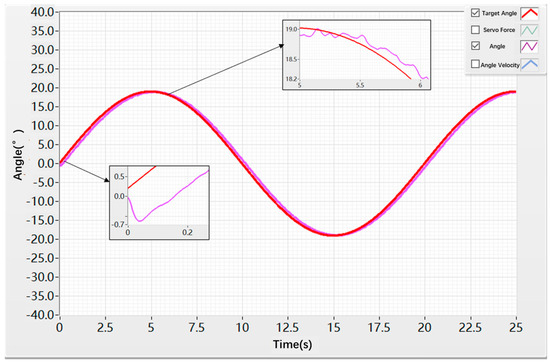
Figure 20.
Angular Sinusoidal Response under PID Control.
The simulation results of the angular velocity under the PID controller are shown in Figure 21. At approximately 0.01 s, the angular velocity reaches around −17.6 deg/s. The oscillation amplitude of the angular velocity remains within ±2 deg/s, with a relatively high oscillation frequency.
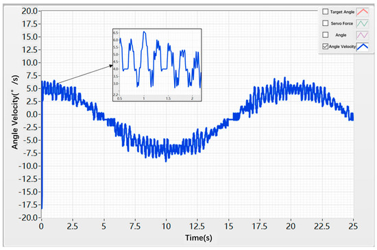
Figure 21.
Angular Velocity Sinusoidal Response under PID Control.
Subsequently, a sinusoidal test was conducted using the hybrid controller for both the speed loop and the position loop. A sinusoidal angle command with an amplitude of 19° and a frequency of 0.05 Hz was applied, and the test duration was set to 25 s. The results, as shown in Figure 22, indicate that the rudder shaft did not exhibit reverse motion at around 0 s and was able to closely follow the reference command. At approximately 5 s, the system exhibited a tracking error of about 0.3 deg, with the overall tracking error maintained within ±0.3 deg throughout the entire motion process.
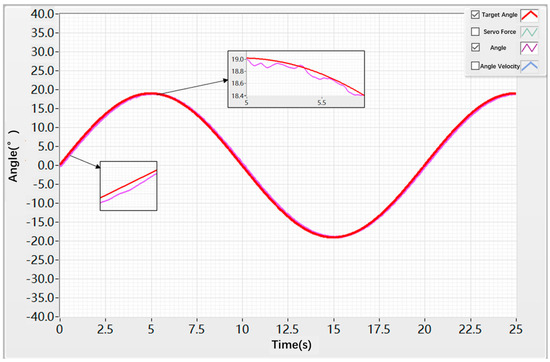
Figure 22.
Angular Sinusoidal Response under Hybrid Control.
The angular velocity simulation results of the hybrid controller are shown in Figure 23. At approximately 0.1 s, the angular velocity reached about 6 deg/s. The oscillation amplitude of the angular velocity remained within ±1 deg/s, with a relatively low oscillation frequency.
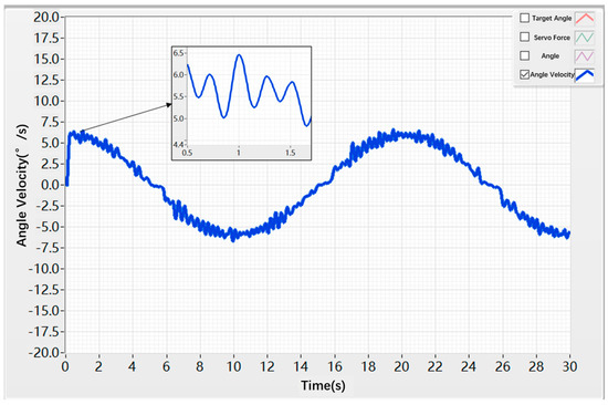
Figure 23.
Angular Velocity Sinusoidal Response under Hybrid Control.
As shown in Figure 20, Figure 21, Figure 22 and Figure 23, for sinusoidal command signals, the backlash and friction present in the control surface actuation system cause the sinusoidal response displacement to exhibit a phase lag, affecting the system’s tracking speed. Meanwhile, due to disturbances from nonlinear factors, both the sinusoidal response displacement and velocity experience certain oscillations, preventing stable signal tracking. Over prolonged operation of the control surface system, this can lead to component wear and even system failure.
Table 6 and Table 7 present the time-domain performance indices of the conventional PID algorithm and the hybrid control algorithm. From the data, it can be concluded that, under sinusoidal motion, the hybrid algorithm effectively suppresses the nonlinear disturbances acting on the servo actuation system, thereby reducing dead-zone effects and oscillations induced by external disturbances.

Table 6.
Time-domain Performance Indicators of Angular Response for the Two Control Algorithms.

Table 7.
Time-domain Performance Indicators of Angular Velocity Response for the Two Control Algorithms.
4. Discussion and Future Work
This study conducted theoretical analysis, simulation, and experimental investigations on the stability control of electromechanical actuation systems based on a hybrid control algorithm, achieving certain results. However, due to limitations in experimental conditions and the researcher’s expertise, some deficiencies remain. Future research will focus on the following aspects:
- In terms of mathematical modeling, the nonlinear factors of the mechanical system, such as backlash and friction, were simplified. As a result, the model lacks sufficient accuracy and requires further refinement.
- Regarding the hybrid control algorithm, the position loop employs an RBF neural network, which incurs a relatively high computational cost and thus requires further optimization.
- In the co-simulation, due to certain idealizations in the friction and backlash models, the nonlinear effects are smoothed. In contrast, in the actual control surface deflection experiments, the real system exhibits more pronounced friction, backlash, and mechanical flexibility effects, leading to discrepancies between the experimental and simulation peak speed results.
- Regarding system experiments, the nonlinear factors are primarily based on the intrinsic friction and backlash of the system, and the method of introducing these nonlinearities requires further refinement.
5. Conclusions
Based on an analysis of the overall structure of the EAS, this study establishes mathematical models for friction and backlash. In the speed loop of the EAS, a Super-Twisting sliding mode controller combined with GPIO is designed, while in the position loop, a hybrid controller integrating RBF neural network with sliding mode control is implemented. Leveraging the advantages of numerical analysis in SIMULINK and dynamic simulation in ADAMS, a co-simulation framework is established to evaluate the hybrid control algorithm under nonlinear effects. Furthermore, a control test bench for the control surface transmission system is constructed to analyze the dynamic and static performance of the system under different control strategies and input commands. Experimental results indicate that the hybrid control method proposed in this study exhibits superior dynamic and static performance as well as enhanced disturbance rejection compared with conventional PID control.
Author Contributions
X.D. was in charge of the whole trial and wrote the manuscript; Y.Z. assisted with sampling and laboratory analyses. All authors have read and agreed to the published version of the manuscript.
Funding
This research was funded by Northwestern Polytechnical University Industry Key Technology Research Fund Project, grant No. HXGJXM202205. The authors also gratefully acknowledge the helpful comments and suggestions of the reviewers which have improved the presentation.
Data Availability Statement
The raw data supporting the conclusions of this article will be made available by the authors on request.
Conflicts of Interest
The authors declare no conflicts of interest.
References
- Chen, W.; Yan, Y.; Qi, Y.; Huang, M.; Li, W. Recent development of aircraft electric propulsion system: A technical review. CES Trans. Electr. Mach. Syst. 2025, 9, 115–130. [Google Scholar] [CrossRef]
- Buticchi, G.; Wheeler, P.; Boroyevich, D. The more-electric aircraft and beyond. Proc. IEEE 2022, 111, 356–370. [Google Scholar] [CrossRef]
- Saha, A.; Ghassemi, M. A review of electrical insulation challenges for electrical powertrain components in the future more and all electric aircraft under low-pressure conditions. IEEE J. Emerg. Sel. Top. Power Electron. 2024, 13, 4521–4536. [Google Scholar] [CrossRef]
- Yuan, S.; Deng, W.; Yi, W.; Yao, J.; Yang, G.; Guan, J. Adaptive Robust Stable Tracking Control of Two-Axis Coupled Electromechanical Actuation System Based on Friction Compensation. Actuators 2025, 14, 396. [Google Scholar] [CrossRef]
- Qiao, G.; Zhang, X.; Liao, R.; Tang, S.; Ma, S. Fatigue analysis and lifespan prediction of the recirculating planetary roller screw mechanism. J. Mech. Sci. Technol. 2025, 39, 1951–1962. [Google Scholar] [CrossRef]
- Cao, J.; Li, Y.; Zhang, X.; Yang, J.; Fan, W. Torque-type backlash inverse control for an electromechanical actuator with active disturbance rejection. IEEE Access 2023, 11, 108688–108696. [Google Scholar] [CrossRef]
- Ruan, W.; Dong, Q.; Zhang, X.; Li, Z. Friction compensation control of electromechanical actuator based on neural network adaptive sliding mode. Sensors 2021, 21, 1508. [Google Scholar] [CrossRef] [PubMed]
- Quattrocchi, G.; Iacono, A.; Berri, P.C.; Vedova, M.D.L.D.; Maggiore, P. A new method for friction estimation in ema transmissions. Actuators 2021, 10, 194. [Google Scholar] [CrossRef]
- Fang, Q.; Zhou, Y.; Ma, S.; Zhang, C.; Wang, Y.; Huangfu, H. Electromechanical actuator servo control technology based on active disturbance rejection control. Electronics 2023, 12, 1934. [Google Scholar] [CrossRef]
- Khanh, N.D.; Kuznetsov, V.E.; Lukichev, A.N.; Chung, P.T. Adaptive control of electromechanical actuator taking into account nonlinear factors based on exo-model. In Proceedings of the 2022 Conference of Russian Young Researchers in Electrical and Electronic Engineering (ElConRus), Saint Petersburg, Russia, 25–28 January 2022. [Google Scholar]
- Gan, L.; Wang, L.; Huang, F. Adaptive backlash compensation for CNC machining applications. Machines 2023, 11, 193. [Google Scholar] [CrossRef]
- Xie, L.; Liu, L.; Zheng, X.; Wang, S. Sliding mode control of aircraft braking system based on LuGre model. J. Huazhong Univ. Sci. Technol. (Nat. Sci. Ed.) 2013, 41, 65–69. [Google Scholar]
- Zhang, K.; Shen, R.; Hu, Z.; Tang, J.; Sun, Z.; Ning, A.; Yang, S. Dynamic modeling and analysis considering friction-wear coupling of gear system. Int. J. Mech. Sci. 2024, 275, 109343. [Google Scholar] [CrossRef]
- Zhang, Q.; Yu, Z.; Liu, H.; Mo, J.; Xiang, Z.; Zhu, S.; Jin, W. Analysis of friction-induced vibration and wear characteristics during high-speed train friction braking process. Tribol. Int. 2024, 196, 109701. [Google Scholar] [CrossRef]
- Zhang, P.; Shi, Z.; Yu, B. Research on friction compensation method of electromechanical actuator based on improved active disturbance rejection control. Actuators 2023, 12, 445. [Google Scholar] [CrossRef]
- Maré, J.-C. Practical considerations in the modelling and simulation of electromechanical actuators. Actuators 2020, 9, 94. [Google Scholar] [CrossRef]
- Wan, Q.; Song, C.; Zhou, Y.; Tong, R.; Ma, S.; Liu, G. Modeling and analysis of the flap actuation system considering the nonlinear factors of EMA, joint clearance and flexibility. Aerospace 2024, 11, 440. [Google Scholar] [CrossRef]
- Fu, B.; Qi, H.; Xu, J.; Yang, Y. Composite sliding mode control of high precision electromechanical actuator considering friction nonlinearity. Actuators 2022, 11, 265. [Google Scholar] [CrossRef]
- Lee, H.-S.; Ko, Y.; Back, J.; Hong, K.-S.; Kim, C.-S. A double-loop robust position and speed control of an electromagnetic actuator against nonlinear model uncertainties. Control Eng. Pract. 2025, 160, 106318. [Google Scholar] [CrossRef]
- Scherer, S.P.; Speckmaier, M.; Gierszewski, D.; Steinert, A.; Holzapfel, F. Compensation of nonlinear transmission effects in electro-mechanical flight control systems. In Proceedings of the AIAA SciTech 2022 Forum, San Diego, CA, USA, 3–7 January 2022. [Google Scholar]
- Zuo, Q.; Wang, B.; Chen, J.; Dong, H. Model Predictive Control of Aero-Mechanical Actuators with Consideration of Gear Backlash and Friction Compensation. Electronics 2024, 13, 4021. [Google Scholar] [CrossRef]
- Maré, J.-C. Requirement-based system-level simulation of mechanical transmissions with special consideration of friction, backlash and preload. Simul. Model. Pract. Theory 2016, 63, 58–82. [Google Scholar] [CrossRef]
- Zhang, P.; Shi, Z.; Yu, B.; Qi, H. Research on the EMA Control Method Based on Transmission Error Compensation. Energies 2024, 17, 2528. [Google Scholar] [CrossRef]
- Hou, Q.; Ding, S. GPIO based super-twisting sliding mode control for PMSM. IEEE Trans. Circuits Syst. II Express Briefs 2020, 68, 747–751. [Google Scholar] [CrossRef]
- Xu, W.; Junejo, A.K.; Liu, Y.; Islam, R. Improved continuous fast terminal sliding mode control with extended state observer for speed regulation of PMSM drive system. IEEE Trans. Veh. Technol. 2019, 68, 10465–10476. [Google Scholar] [CrossRef]
- Yan, J.; Wang, H.; Huang, S.; Lan, Y. Disturbance Observer-Based Backstepping Control of PMSM for the Mine Traction Electric Locomotive. Math. Probl. Eng. 2018, 2018, 7253210. [Google Scholar] [CrossRef]
- Ding, S.; Park, J.H.; Chen, C.-C. Second-order sliding mode controller design with output constraint. Automatica 2020, 112, 108704. [Google Scholar] [CrossRef]
- Tian, M.; Wang, B.; Yu, Y.; Dong, Q.; Xu, D. Adaptive active disturbance rejection control for uncertain current ripples suppression of PMSM drives. IEEE Trans. Ind. Electron. 2023, 71, 2320–2331. [Google Scholar] [CrossRef]
- Zhang, Z.; Yang, X.; Wang, W.; Chen, K.; Cheung, N.C.; Pan, J. Enhanced sliding mode control for PMSM speed drive systems using a novel adaptive sliding mode reaching law based on exponential function. IEEE Trans. Ind. Electron. 2024, 71, 11978–11988. [Google Scholar] [CrossRef]
- Liu, X.; Deng, Y.; Liu, J.; Cao, H.; Xu, C.; Liu, Y. Fixed-time integral terminal sliding mode control with an adaptive RBF neural network for PMSM speed regulation. Control Eng. Pract. 2025, 156, 106236. [Google Scholar] [CrossRef]
- Guo, Z.; Li, J.; Yan, M.; Wang, G. Composite speed control based on an improved gain-adaptive super-twisting sliding mode observer for a permanent magnet synchronous motor. Control Eng. Pract. 2025, 157, 106241. [Google Scholar] [CrossRef]
- Ma, J.; Yao, Z.; Yao, J. Fixed-time sliding mode control of electro-hydrostatic actuators with adaptive neural network compensation. Control Eng. Pract. 2025, 165, 106616. [Google Scholar] [CrossRef]
- Zhao, K.; Jia, N.; She, J.; Dai, W.; Zhou, R.; Liu, W.; Li, X. Robust model-free super-twisting sliding-mode control method based on extended sliding-mode disturbance observer for PMSM drive system. Control Eng. Pract. 2023, 139, 105657. [Google Scholar] [CrossRef]
- Ghani, M.F.; Faudzi, A.A.M.; Ghazali, R.; Mohamaddan, S. Application of Fuzzy Logic Sliding Mode Control Approach with PID Structure for Electro-Hydraulic Actuator Tracking System. IEEE Access 2025, 13, 97818–97834. [Google Scholar] [CrossRef]
- Song, Z.; Zhou, W. PMSM disturbance resistant adaptive fast super-twisting algorithm speed control method. IEEE Access 2024, 12, 138155–138165. [Google Scholar] [CrossRef]
- Guan, M.; Qu, C.; Lv, J.; Yang, L.; Li, X. A novel RBF neural network–based sliding mode controller for a master–slave motor coordinated drive system. Int. J. Adv. Manuf. Technol. 2024, 133, 4907–4921. [Google Scholar] [CrossRef]
- Zhao, W.; Gu, L. RBF-Based Fractional-Order SMC Fault-Tolerant Controller for a Nonlinear Active Suspension. Machines 2024, 12, 270. [Google Scholar] [CrossRef]
- Zhang, H.; Liu, Y. Adaptive RBF neural network based on sliding mode controller for active power filter. Int. J. Power Electron. 2020, 11, 460–481. [Google Scholar] [CrossRef]
Disclaimer/Publisher’s Note: The statements, opinions and data contained in all publications are solely those of the individual author(s) and contributor(s) and not of MDPI and/or the editor(s). MDPI and/or the editor(s) disclaim responsibility for any injury to people or property resulting from any ideas, methods, instructions or products referred to in the content. |
© 2025 by the authors. Licensee MDPI, Basel, Switzerland. This article is an open access article distributed under the terms and conditions of the Creative Commons Attribution (CC BY) license (https://creativecommons.org/licenses/by/4.0/).