Article

Prescribed-Performance-Based Sliding Mode Control for Piezoelectric Actuator Systems

by
Shengjun Wen
1,*,
Shixin Zhang
2 and
Jun Yu
1
1
Zhongyuan Petersburg Aviation College, Zhongyuan University of Technology, Zhengzhou 451191, China
2
Department of Electrical and Engineering, Zhongyuan University of Technology, Zhengzhou 451191, China
*
Author to whom correspondence should be addressed.
Actuators 2025, 14(11), 516; https://doi.org/10.3390/act14110516
Submission received: 18 August 2025 / Revised: 16 October 2025 / Accepted: 20 October 2025 / Published: 25 October 2025
(This article belongs to the Section Actuator Materials)

Abstract

A prescribed-performance-based sliding mode control method with feed-forward inverse compensation is proposed in this study to improve the micropositioning accuracy and convergence speed of a piezoelectric actuator (PEA). Firstly, the piezo-actuated micropositioning system is described by a Hammerstein structure model, and an inverse Prandtl–Ishlinskii (PI) model was employed to compensate for its hysteresis characteristics. Then, considering modelling errors, inverse compensation errors, and external disturbances, a new prescribed performance function (PPF) with an exponential dynamic decay rate was developed to describe the constrained region of the errors. We then transformed the error into an unconstrained form by constructing a monotonic function, and the sliding variables were obtained by using the transformation error. Based on this, a sliding mode controller with a prescribed performance function (SMC-PPF) was designed to improve the control accuracy of PEAs. Furthermore, we demonstrated that the error can converge to the constrained region and the sliding variables are stable within the switching band. Finally, experiments were conducted to verify the speed and accuracy of the controller. The step-response experiment results indicated that the time taken for SMC-PPC to enter the error window was 8.1 and 2.2 ms faster than that of sliding mode control (SMC) and PID, respectively. The ability of SMC-PPF to improve accuracy was verified using four different reference inputs. These results showed that, for these different inputs, the root mean square error of the SMC-PPF was reduced by over 39.6 % and 52.5 % , compared with the SMC and PID, respectively.

1. Introduction

With the increasing demand for precision positioning in modern science and industrial production, traditional materials are struggling to meet the needs of positioning and drive control, as a result, micro-nano drive systems based on intelligent materials play a vital role in in this field [1,2]. Piezoelectric actuators(PEAs), which use piezoelectric ceramics as drive elements, have seen an increasingly more comprehensive range of applications in robotics, aerospace, semiconductor equipment, and medical devices due to their fast response times, high positioning accuracy, and high output torque [3,4,5]. However, the inherent nonlinear hysteresis of piezoelectric ceramics severely affects the positioning accuracy and response speed of PEAs, limiting their use in industrial applications [6,7]. Therefore, accurately modelling a PEA and achieving high-precision tracking control are pressing problems at present.
Currently, there are two broad control methods for PEAs. The first method effectively suppresses the hysteresis characteristics by adjusting the controller’s parameters online according to the model’s features [8,9,10,11]. A finite-time adaptive terminal sliding mode control was proposed in [12], where the nonlinear hysteresis and the external disturbance errors were estimated online using a disturbance estimation method, and the corresponding adaptive rate was derived from achieving tracking error convergence in finite time while eliminating sliding mode control (SMC) jitter. The authors of [13], designed a neural network parameter self-tuning control system to describe a PEA, with two nonlinear equations containing unknown variables. Then, they approximated the unknown parameters of the nonlinear equations using an adaptive neural network to achieve high-accuracy tracking of the PEA’s position. However, this design of controllers is often complex, and stability is difficult to guarantee. The second method establishes a model describing the exact hysteresis characteristics. Commonly used hysteresis models are the Preisach, Bouc Wen (B–W) and Prandtl–Ishlinskii (PI) models. Then, according to the established hysteresis model, the inverse of the hysteresis model is constructed, the hysteresis is eliminated using feed-forward compensation methods, the PEA is approximated as a linear system, and then, conventional control methods are used to achieve the tracking of the engagement accuracy [14,15,16,17]. The authors of [18] constructed the inverse of the B–W model, compensating for the PEA’s hysteresis, and then tracked the reference input signal using proportional integral sliding-mode control. The author of [19] presented an adaptive generalised Maxwell-slip algorithm for the online identification and compensation of hysteresis. The authors of [20] introduced a load correction factor to the PI model to improve the control accuracy under different loads.
Both of the above-mentioned methods are effective and popular in their respective applications. However, algorithms using neural networks or complex adaptive online adjustments require high computational efficiency. In actual industrial control, a very small microprocessor unit (MCU) is usually used, which has low computational efficiency and makes it difficult to handle complex calculations quickly; thus, the development of such methods is restricted [21,22,23]. In the other control type, an operator model is constructed to obtain the analytic inverse or pseudo-inverse, and a feedback control is designed to track the reference signal, where only a few operators are required to describe the hysteresis characteristics of piezoelectricity, and the amount of computation is also relatively small. However, eliminating hysteresis is completely dependent on the feed-forward compensation in these types of methods; there are still modelling and compensation errors. When the convergence region of the tracking error is required, it is unavoidable to have chattering in the SMC, which will reduces the micropositioning accuracy [24,25,26,27,28].
Among the aforementioned hysteresis models, PI model features the simplest identification process and the lowest computational complexity. Furthermore, it possesses an explicit analytical inverse that can be solved directly from the model description in a single step. Therefore, this study selects the PI model to describe hysteresis. Based on this model, this article proposes a prescribed-performance-based sliding mode control method with feed-forward inverse compensation to further enhance the positioning capability of the PEA. The main contributions include three aspects. Firstly, the modelling error and feed-forward compensation error are taken into account when designing the controller, and the tracking error one step ahead is estimated to improve the control accuracy. Secondly, a new prescribed performance function and the corresponding transformation error are proposed to obtain a faster convergence speed and higher precision. Finally, based on the prescribed performance function and the transformation error, a discrete-time sliding mode controller is designed, the convergence of the error and system stability are proved, and the effectiveness of the proposed method is verified with the experimental results.
This study is organised as follows. Section 2 briefly describes the PEA system model. A prescribed performance-based sliding mode control is designed and analysed in Section 3. The proposed method is verified in Section 4. Finally, Section 5 concludes this article with a summary of the core aspects.

2. Description of the PEA System

Hysteresis is a static property of a PEA system. This is usually described as a PI model. The dynamic properties can be described as a second-order difference equation. The PI model is easily linearised by means of inverse compensation [29]. Since there are errors in both modelling and compensation, the model after compensation can be defined as
y m ( k ) = i = 1 n 1 a ( i ) y m ( k i ) + j = 1 m b ( j ) u c ( k j + 1 ) + o ( k ) ,
where a ( i ) and b ( i ) are the coefficients of the difference equation, which are generally obtained by parameter identification. u c ( k ) is the control input of the PEA, and y m ( k ) is the output of the system measured by the displacement sensor. o ( k ) is the combined error within the system, which consists of modelling error, back-compensating error and external disturbances.

3. Design of Prescribed Performance Sliding Mode Controller

The input–output relationship of the entire control system is shown in Figure 1. The inverse PI feed-forward compensates for the hysteresis of the PEA system. The SMC-PPF studied in this article is used for closed-loop feedback control. This composite control method, which combines feed-forward and feedback, is a common approach in PEA systems.

3.1. Definition of PPF

For any controller, the control error of the actual system is bounded and PPC uses this feature to keep the error inside the convergence region through the algorithm. The first step in implementing PPC is to use two prescribed performance functions (PPF) to represent the convergence region of the error, in this study, a new PPF is defined to make the positioning error have a faster convergence speed and a smaller steady-state value. The designed PPF is
ϱ ( k ) = T d k T d α ϱ ( 0 ) ϱ ( ) + ϱ ( ) i f k T d ϱ ( k ) = ϱ ( ) i f k > T d .
From (2), it can be seen that when k T d , the PPF decays at an exponential rate and α is the decay index, which means that the localisation error will decay to a steady state at an exponential rate, and when k > T d , the value of the PPF function is constant.
In this study, a new upper and lower bound for the control error is defined
u ( k + 1 ) = ( 1 ς ) u ( k ) + ς
l ( k + 1 ) = ( 1 ς ) l ( k ) + ς
where ς is a constant satisfying 0 < ς < 1 . u ( 0 ) and l ( 0 ) are both greater than zero, and lim k u ( k ) = lim k l ( k ) = 1 .

3.2. Constraint Conditions and Transformation Errors

Assuming the reference input is y r ( k ) for the PEA, the position error can be defined as
e ( k ) = y r ( k ) y m ( k ) ,
where y r is the reference input signal and y m is the measured output displacement. According to (2), (3), and (4), the constraint bounds on the position error e ( k ) of the PEA is given as
l ϱ ( k ) + ξ < e ( k ) < u ϱ ( k ) ξ ,
where ξ is a positive number, subtract ξ from the left side of (13) and add ξ to the right side, which makes the constraint bound on the position error smaller.
The constrained form of the error in Equation (6) is not conducive to controller design, so it is considered to be converted to an unconstrained form with no upper or lower limits. Then, choose a strictly monotonically increasing function Θ ( ( k ) ) . The principle for choosing this strictly increasing function is that it needs to satisfy l ( k ) < Θ ( ( k ) ) < u ( k ) in the real number line. It is chosen as
Θ ( ( k ) ) = u ( k ) e ( k ) l ( k ) e ( k ) e ( k ) + e ( k ) .
Since Θ ( · ) is a monotonic function, there must be an inverse function. In this study, in order to improve the computational speed of the controller, the use of the logarithmic function is abandoned, adopting ϕ ( k ) in (8) as the transformation error
ϕ ( k ) = l ( k ) ϱ ( k ) e ( k ) u ( k ) ϱ ( k ) + e ( k ) .
ϕ ( k ) is monotonically consistent with e ( k ) , and as long as ϕ ( k ) is guaranteed to converge within a specific range, e ( k ) is also guaranteed to converge.
Equation (8) provides the final form of the conversion error, which will be used for the design of the sliding surface. The most straightforward approach is to invert Function (7) and then disregard its logarithmic operation. This method is justified because the monotonicity between the logarithmic function and its independent variable remains consistent. Taking Equations (2)–(4) into Equation (8) yields the most direct representation of the conversion error.

3.3. Design of SMC

Design the switching surface of the SMC-PPF as
L ( k ) = ϕ ( k ) μ ϕ ( k ) + μ 1 ,
where μ is a relatively small parameter that satisfies 0 < μ < 1 . The position error of the PEA one step ahead is
e ( k + 1 ) = y r ( k + 1 ) + i = 1 2 a ( i ) y ( k i + 1 ) j = 1 2 b ( j ) u ( k j + 1 ) o ( k )
then, the corresponding transformation error ϕ ( k + 1 ) and sliding variable L ( k + 1 ) are
ϕ ( k + 1 ) = l ( k + 1 ) ϱ ( k + 1 ) e ( k + 1 ) u ( k + 1 ) ϱ ( k + 1 ) + e ( k + 1 )
L ( k + 1 ) = ϕ ( k + 1 ) μ ϕ ( k + 1 ) + μ 1 .
In this study, we treat the model’s error and the feed-forward compensation error as a perturbation and use a perturbation estimation technique to obtain an estimate of the overall error
o ^ ( k ) o ( k 1 ) = y m ( k ) + i = 1 2 a ( i ) y m ( k i ) j = 1 2 b ( j ) u c ( k j ) .
The primary reason for employing Equation (13) to estimate the o ^ ( k ) lies in its straightforward computational process, which can enhance the computational speed of the controller. In a real system, there is still some error before the estimated value of the perturbation and the true value, but this error is unmeasurable and so small that it can be disregarded. Bringing (11) and (12) into L ( k + 1 ) = 0 yields
y r ( k + 1 ) i = 1 2 a ( i ) y m ( k i + 1 ) j = 1 2 b ( j ) u c ( k j + 1 ) o ^ ( k ) u ( k + 1 ) μ ϕ ( k ) + 1 μ l ( k + 1 ) μ ϕ ( k ) + 2 μ ϱ ( k + 1 ) = 0 ,
the output of the SMC-PPF can be easily derived from (14)
u e q ( k ) = { y r ( k + 1 ) i = 1 2 a ( i ) y m ( k j + 1 ) j = 2 2 b ( j ) u e q ( k j + 1 ) o ^ ( k ) u ( k + 1 ) μ ϕ ( k ) + 1 μ l ( k + 1 ) μ ϕ ( k ) + 2 μ ϱ ( k + 1 ) } / b ( 1 ) .
In order to make the error convergence faster, a control output based on the convergence rate is added to the SMC-PPF, which makes the time of the dynamic process shorter. Then, the total control its output is
u c ( k ) = u e q ( k ) + u s w ( k )
u s w = 1 b ( 1 ) K s i g n ( L ( k ) ) ,
where s i g n ( · ) is the sign function. When L ( k ) > 0 , its function value is 1. When L ( k ) < 0 , whose function value is −1, K satisfies the following inequality
ξ + o ( k ) < K < ( 1 μ ) ϱ ( ) μ ( u ( 0 ) + l ( 0 ) ) ϱ ( 0 ) ξ ξ + ( 2 μ ) .
Taking Equations (15) and (17) into (16) yields
u c ( k ) = u e q ( k ) + u s w ( k ) = { y r ( k + 1 ) i = 1 2 a ( i ) y m ( k j + 1 ) j = 2 2 b ( j ) u c ( k j + 1 ) o ^ ( k )       u ( k + 1 ) μ ϕ ( k ) + 1 μ l ( k + 1 ) μ ϕ ( k ) + 2 μ ϱ ( k + 1 ) + K s i g n ( L ( k ) ) } / b ( 1 ) .

3.4. Stability Analysis

From Equation (8), the monotonicity of transformation error ϕ ( k ) and tracking error e ( k ) is the same, and tracking error e ( k ) satisfies Equation (6), so transformation error ϕ ( k ) must also converge in some region, and if tracking error e ( k + 1 ) , which is one step ahead, still satisfies the above region, then the transformation error must also converge.
By bringing the control signal (19) into (10), the tracking error of one step ahead can be obtained as follows
e ( k + 1 ) = Λ 1 ( k ) ϕ ( k ) + Λ 2 ( k ) μ ϕ ( k ) + 2 μ o ( k ) + K s i g n ( L ( k ) ) ,
where Λ 1 and Λ 2 are defined, respectively, as
Λ 1 = μ u ( k + 1 ) ϱ ( k + 1 ) ,
Λ 2 = ( 1 μ ) u ( k + 1 ) l ( k + 1 ) ϱ ( k + 1 ) .
From Equation (18), it follows that
ξ 2 K < o ^ ( k ) K s i g n ( L ( k ) ) < 2 K ξ ,
taking Equation (8) into Equation (6) yields
ξ ( u ( 0 ) + l ( 0 ) ) ϱ ( 0 ) ξ < ϕ ( k ) < ( u ( 0 ) + l ( 0 ) ) ϱ ( 0 ) ξ ξ .
Furthermore, we can derive that
K < ( 1 μ ) ϱ ( ) μ ( u ( 0 ) + l ( 0 ) ) ϱ ( 0 ) ξ ξ + ( 2 μ ) < ( 1 μ ) ϱ ( ) μ ϕ ( k ) + ( 2 μ ) .
Taking Equation (23) into (25) gives
ξ 2 ( 1 μ ) ϱ ( ) μ ϕ ( k ) + 2 μ < o ( k ) K s i g n ( L ( k ) ) < 2 ( 1 μ ) ϱ ( ) μ ϕ ( k ) + 2 μ ξ .
Taking Equation (20) into (26) gives
e ( k + 1 ) < Λ 1 ( k ) ϕ ( k ) + Λ 2 ( k ) + 2 ρ ( ) μ ϕ ( k ) + 2 μ ξ .
The above equation can be thought of as an increasing function with respect to ϕ ( k ) . Taking the limit on the right-hand side of Equation (27) yields
lim ϕ ( k ) Λ 1 ( k ) ϕ ( k ) + Λ 2 ( k ) + 2 ϱ ( ) μ ϕ ( k ) + 2 μ ξ = u ( k + 1 ) ϱ ( k + 1 ) ξ .
It can be obtained
e ( k + 1 ) < u ( k + 1 ) ϕ ( k + 1 ) ξ .
The same derivation on the right-hand side of the inequality leads to
l ( k + 1 ) ϱ ( k + 1 ) + ξ < e ( k + 1 ) .
From Equation (29) and Equation (30), it can be easily obtained that
l ( k + 1 ) ϱ ( k + 1 ) + ξ < e ( k + 1 ) < u ( k + 1 ) ϱ ( k + 1 ) ξ .
From Equation (31), it can be seen that the tracking error e ( k + 1 ) of one step ahead still satisfies the prescribed convergence region, which indicates that the tracking error of the PEA system can remain in the convergence region once it has entered it. Therefore, the controller proposed in this study ensures that the PEA is stable.

4. Experimental Verification

In this study, the PEA control system based on piezoelectric ceramics is shown in Figure 2, and the whole experimental system consists of the following main parts: (1) experimental piezo-actuated displacement system PS1H80-030U(Physik Instrumente Co., Ltd., Karlsruhe, Germany), its displacement stroke is 40 μ m; (2) power driver PH301(Physik Instrumente Co., Ltd., Karlsruhe, Germany), its magnification is 15 times (amplifying the input voltage from 0 to 15 V to 0 to 150 V and outputting it); (3) signal conditioning moudle SAB101, which converts displacements ranging from 0 to 100 μ m into voltage signals ranging from 0 to 10 V; (4) signal input/output module AIO-163202F (CONTEC Co., Ltd., Osaka, Japan), which is equipped with 16-bit 32-channel analogue inputs and two-channel analogue outputs, with a sampling frequency of 500 kHz. And its noise level is ±0.1% of the full scale.
The computer generates the target motion trajectory and transmits it via Ethernet to the signal input/output module. This module outputs an actual analogue voltage signal to the power driver, which amplifies the signal by a factor of 15 before applying it to the piezoelectric actuator. The voltage signal collected by the displacement sensor undergoes signal conditioning before being transmitted back to the signal input/output module, thereby providing feedback to the computer.

4.1. Model Identification

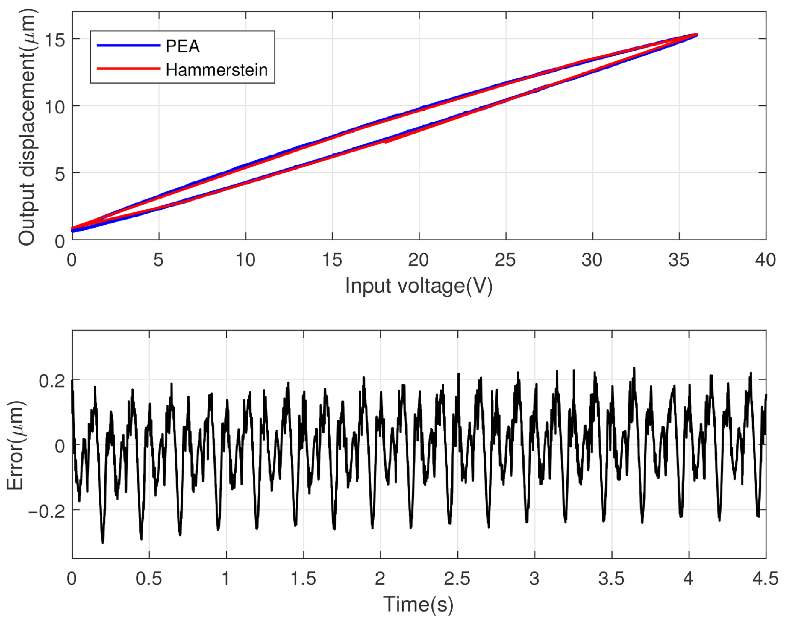
The accurate PEA model is established to compensate or control it easier. As shown in Figure 3, the PEA’s input voltage and output displacement are collected to establish the PI model. This study uses a voltage signal with a frequency of 10 Hz and an amplitude of 36 V as the excitation source, and the Hammerstein model is obtained by least squares identification after the output displacement is collected. Table 1 shows the results of parameter identification.
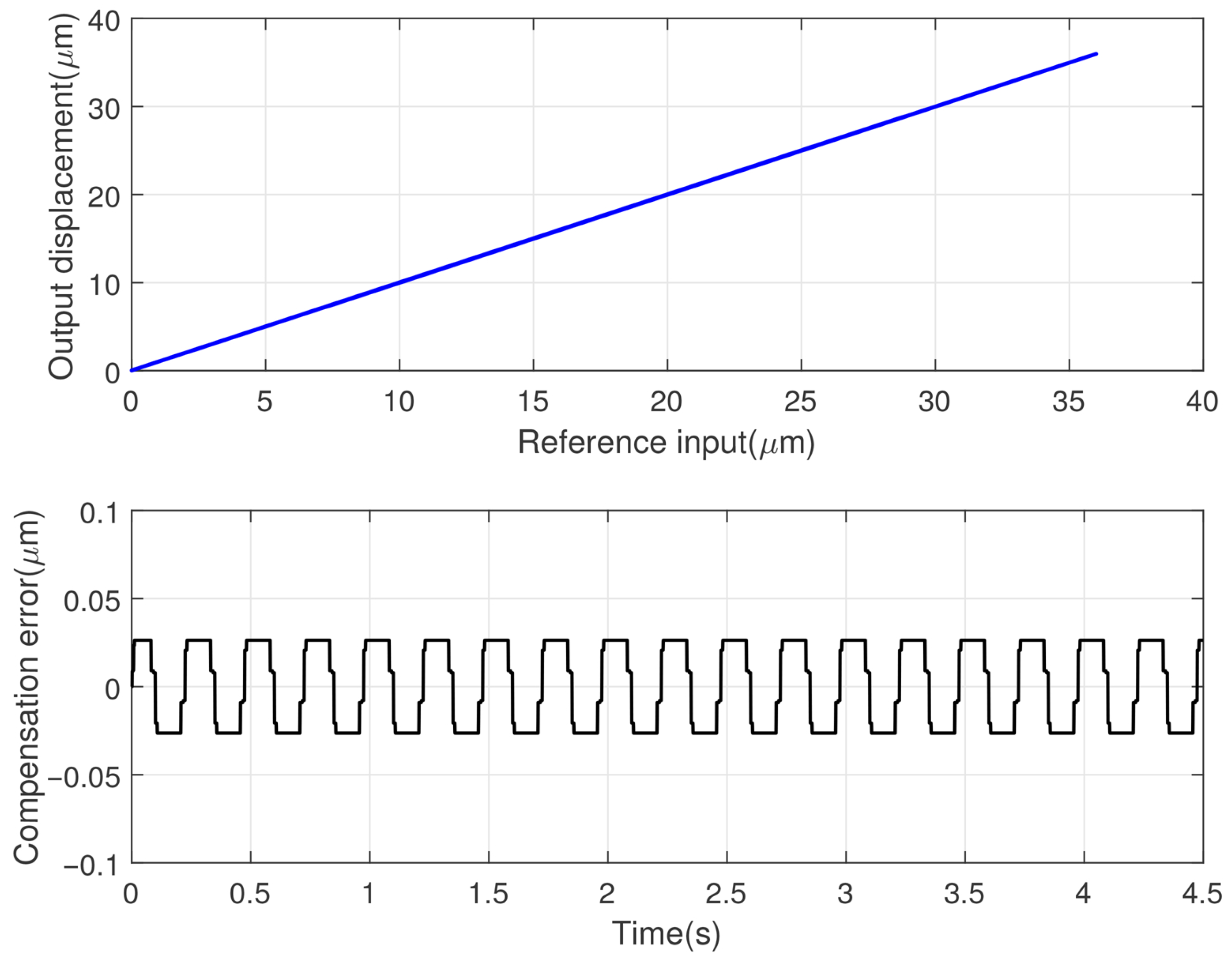
Figure 3 represents the PEA system input–output relationships. It also shows how well the Hammerstein model fits the PEA. The modelling error can be seen to be within ±0.3 μ m. Figure 4 demonstrates the effect of feed-forward inverse compensation and the compensation error, which is also within ±0.027 μ m.

4.2. Experimental Results

4.2.1. Reference Input Signals

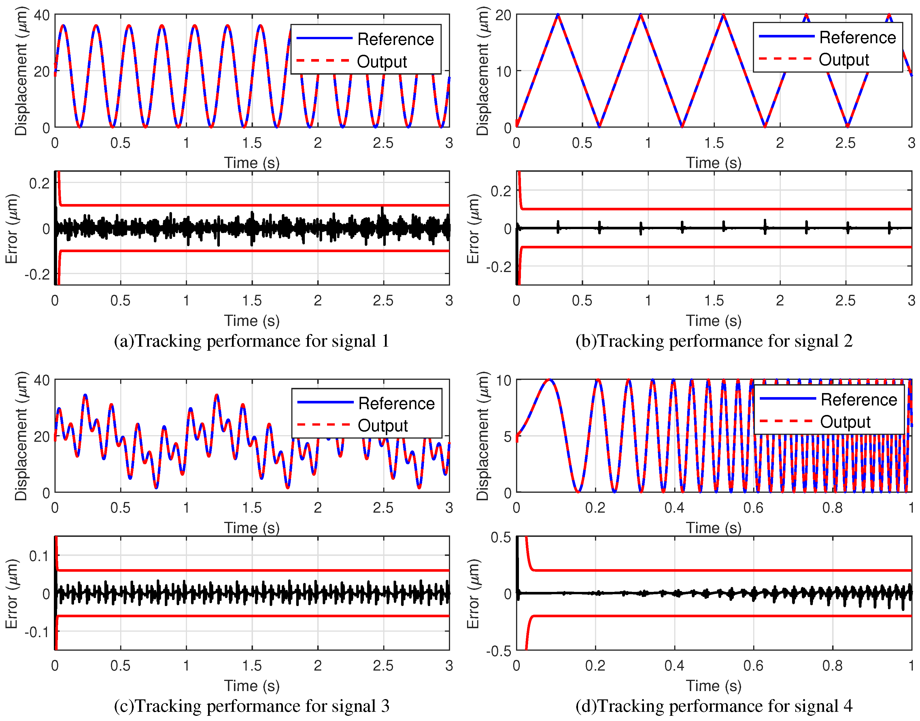
To verify the superiority of the control method proposed in this study in different situations, the following comparison is made using four different reference signals as excitation sources and PID and SMC: Signal 1: y d ( k ) = 18 s i n ( 8 π T s k ) + 18 ; Signal 2: y d ( k ) = 10 a r c c o s ( c o s ( 10 T s k ) ) / a r c c o s ( 0 ) ; Signal 3: y d ( k ) = 6 s i n ( 2 π T s k ) + 6 s i n ( 10 π T s k ) + 6 s i n ( 20 π T s k ) + 18 ; Signal 4: y d ( k ) = 5 s i n ( 2 π k = 1 n ( f s t a r t + ( f e n d f s t a r t ) T s k / T ) ) + 5 .
In the above expressions for the excitation signal, T s denotes the sampling period, and f s t a r t and f e n d denote the start frequency and the termination frequency of the sweep signal, respectively. In this study, the controller’s sampling period is 0.0005 s, the start frequency of the frequency sweep signal is 1 Hz, the end frequency is 30 Hz, this signal is typically used to verify the frequency response of systems in industrial applications. When employed as a reference input here, it reflects the system’s control performance across a continuously varying frequency range. The mixed frequency signal is mixed with 1 Hz, 5 Hz, and 10 Hz signals, it reflects the model coefficients’ ability to fit hysteresis in signals of different frequencies, as well as the controller’s performance in managing hysteresis that has not been fully compensated. The frequency of the triangle wave is 1.59 Hz, which physically represents uniform reciprocating motion, a common operating condition for actuators. And the signal 1 is a sinusoidal signal with a frequency of 4 Hz, which can reflect the dynamic tracking performance of the controller.

4.2.2. Tracking Performance

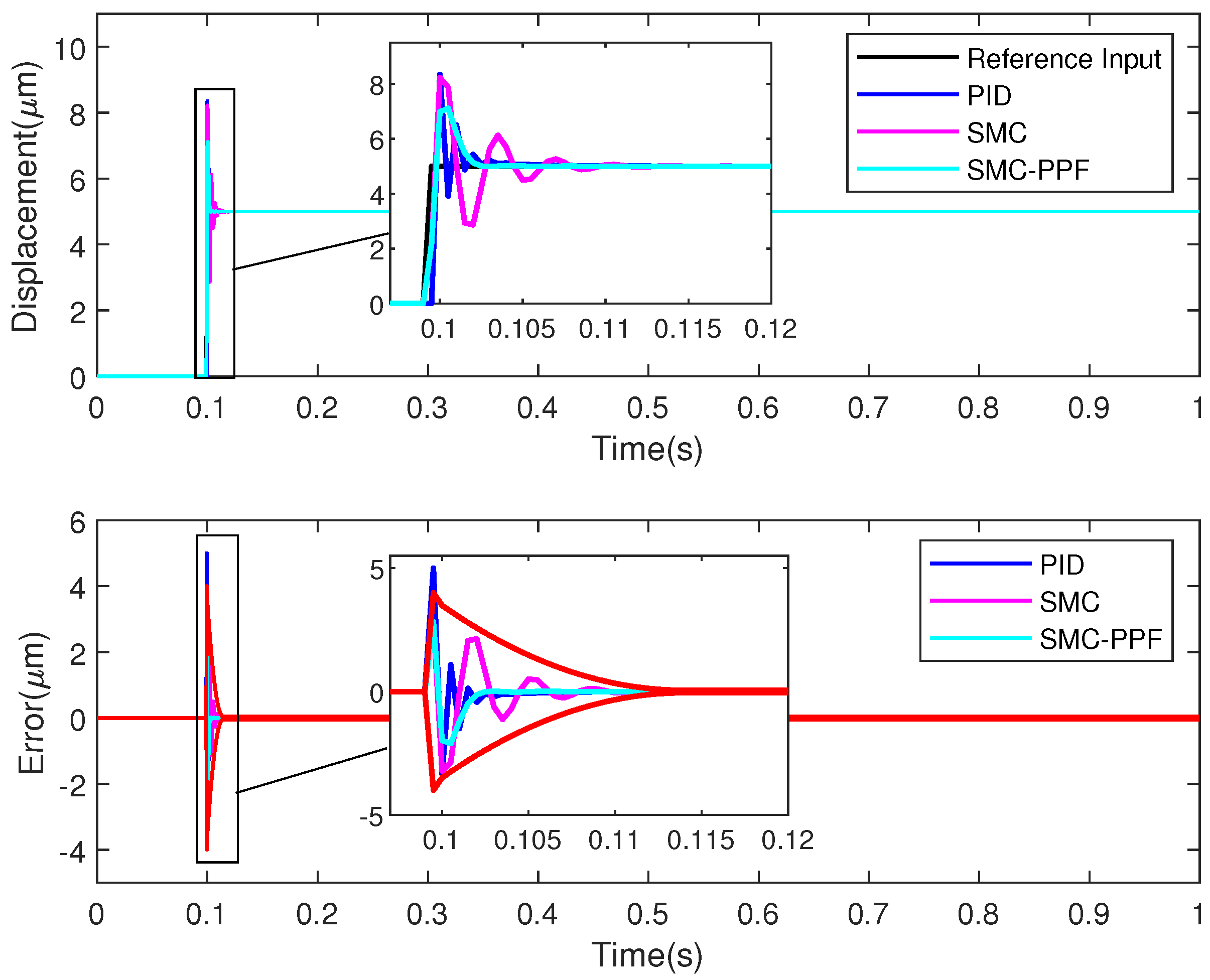
To verify the rapidity of the whole control system, this study designs the step control experiment and compares it with the ordinary sliding mode control and PID control. In the step response shown in Figure 5, if the error enters the error window of 50 nm as the boundary, the PPC takes only 3.1 ms to complete the calibration, while the PID and SMC take 5.5 ms and 11.2 ms, respectively, showing that the calibration time of the PPC is shorter. Table 2 shows the controller parameters during the step response experiment.
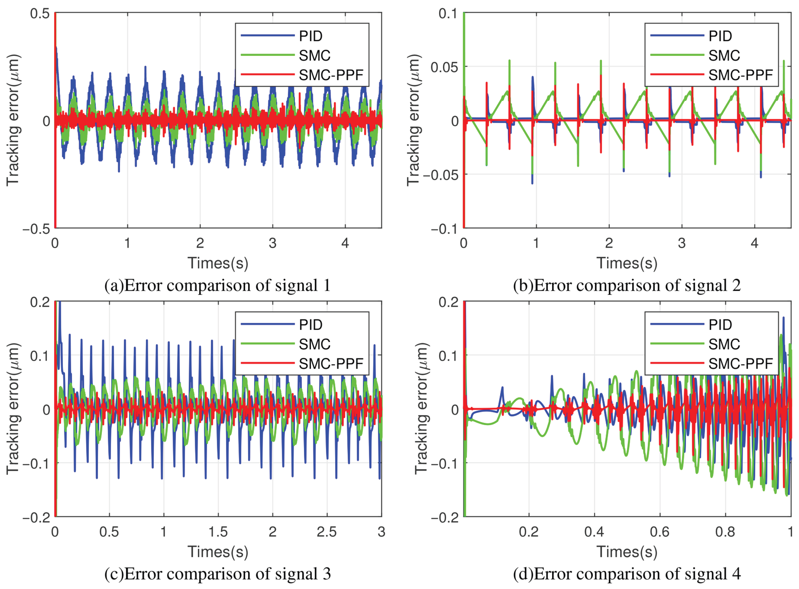
Figure 6 reflects the performance of the control method proposed in this study under the action of different excitation signals. It is well known that the sliding mode control can be classified into dynamic and steady-state processes according to the switching law, and thanks to the design in Section 3.3 of this study, it can be seen from these figures that the control method proposed in this study has good performance in both dynamic and steady-state processes. From Figure 7, it can be seen that the control method proposed in this study outperforms both the PID control and the SMC control under four different excitation signals, and a more uniform frequency distribution.
These errors are further analysed precisely in Figure 8, where RMSE denotes the root mean square error, MEAN denotes the mean value of the steady-state error, and the VAR denotes the variance of error. These three values evaluate the performance of the controller. The statistics for the four different excitation sources show that the RMSE, MEAN and VAR of the SMC-PPF are smaller than those of the PID and the SMC for the same excitation signals. The respective equations for RMSE, MEAN, and VAR are as follows:
R M S E = 1 n k = 1 n ( y r ( k ) y m ( k ) ) 2 .
M E A N = 1 n k = 1 n ( y r ( k ) y m ( k ) ) .
V A R = 1 n k = 1 n ( e ( k ) M E A N ) 2 .
The tracking error as a percentage of the input signal is 1.45 % when the reference signal is signal 4, which is the maximum percentage value among the four signals tested. Compared with PID, the proposed control method reduces the root mean square error by more than 52.5 % , the average value of steady-state error is reduced by more than 14.1 % and the variance is reduced by more than 16.5 % . Compared with SMC control, the root mean square error is reduced by more than 39.6 % , the average value of steady-state error is reduced by more than 9.5 % and the variance is reduced by more than 15.1 % .

5.  Conclusions

In this study, a model with a Hammerstein structure is developed for a PEA with hysteresis characteristics, where the modelling error is within ±0.3 μ m. An inverse PI is designed to compensate for the nonlinear hysteresis of the PEA, and its compensation error is within 0.027 μ m. Considering the convergence region and modelling and compensation errors, the SMC-PPF is proposed by predicting the error one step ahead. A step-response experiment was conducted to verify SMC-PPF speed. The results show that the time taken for the proposed method to enter the error window is 2.2 and 8.1 ms shorter than for PID and SMC, respectively. Four different reference signals were used to verify the steady-state error of the controller. The results of these experiments show that, in terms of root mean square error, SMC-PPF is reduced by over 39.6 % and 52.5 % compared with SMC and PID, respectively, the average error is reduced by over 9.5 % and 14.1 % compared to SMC and PID, respectively, and the variance is reduced by over 16.5 % and 15.1 % compared to SMC and PID, respectively. These comparisons demonstrate that the proposed method outperforms PID and SMC in terms of both speed and accuracy.
Although the control method proposed in this study has been validated using four different reference signals, demonstrating superior performance compared to PID and SMC, it still has limitations in practical applications. On one hand, as an actuator, point-to-point motion planning should be considered during actual movement, incorporating acceleration and jerk into trajectory planning. On the other hand, in high-speed motion scenarios, the large rate of position change may cause errors to exceed prescribed boundaries, leading to control failure. Therefore, future research could explore making these preset boundaries adaptive to handle more complex motion conditions.

Author Contributions

Conceptualization, S.W.; Methodology, S.Z.; Software, S.Z. and J.Y.; Validation, J.Y.; Formal analysis, S.W.; Investigation, S.W. and J.Y.; Resources, S.Z.; Data curation, S.Z.; Writing—original draft, S.Z.; Writing—review & editing, S.Z.; Visualization, S.Z. and J.Y.; Supervision, S.W.; Project administration, S.W.; Funding acquisition, J.Y. All authors have read and agreed to the published version of the manuscript.

Funding

This work was supported in part by the Key Research and Development Project of Henan Province (231111221600); Natural Science Foundation of Shandong Province (ZR2023MF024); Support Plan for Science and Technology Innovation Teams in Higher Education Institutions of Henan Provine (24IRTSTHN024).

Data Availability Statement

Data are contained within the article.

Conflicts of Interest

The authors declare no conflicts of interest.

References

  1. Dai, Y.; Li, D.; Wang, D. Review on the Nonlinear Modeling of Hysteresis in Piezoelectric Ceramic Actuators. Actuators 2023, 12, 442. [Google Scholar] [CrossRef]
  2. Jung, W.; Cho, K. Deep Learning and NLP-Based Trend Analysis in Actuators and Power Electronics. Actuators 2025, 14, 379. [Google Scholar] [CrossRef]
  3. Zhang, F.; Zhang, K.; Cheng, H.; Gao, H.; Cai, K. Ultrasonic Guided Wave Health Monitoring of High-Temperature Aircraft Structures Based on Variational Mode Decomposition and Fuzzy Entropy. Actuators 2024, 13, 411. [Google Scholar] [CrossRef]
  4. Serdar, K.; Anton, R. Vibration Control of Satellite Antennas via NMPC and NARX Neural Networks. IEEE Trans. Aerosp. Electron. Syst. 2025, 61, 9406–9433. [Google Scholar] [CrossRef]
  5. Li, X.; Peng, S.; Guo, K.; Tian, F.; Xu, G. Frequency-Convertible Driving Principle of Low-Frequency Linear Actuation with Double Orthogonal Wafer Oscillators. IEEE Trans. Instrum. Meas. 2024, 73, 7500611. [Google Scholar] [CrossRef]
  6. Gu, X.; Yang, W.; Dong, L.; Zhou, J. Investigation of Hysteresis Phenomena and Compensation in Piezoelectric Stacks for Active Rotor. Actuators 2025, 14, 327. [Google Scholar] [CrossRef]
  7. Lin, J.; Qi, C.; Xue, Y.; Wang, Y.; Liu, X.; Gao, F. Actuation Force Modeling and Identification for Piezoelectric Actuator with Neural Network Compensator and Nonlinear Hysteresis. IEEE Sens. J. 2024, 24, 1606–1614. [Google Scholar] [CrossRef]
  8. Zeng, X.; Nan, F.; Li, T.; Mo, C.; Su, J.; Wei, K.; Zhang, X. Integrating Strain Gauge Feedback with Adaptive Sliding Mode Motion Control for Piezoelectric Nanopositioning Stage. Actuators 2025, 14, 79. [Google Scholar] [CrossRef]
  9. Zhang, J.; Fei, Y.; Li, J.; Li, Y. Memory-Enhanced Neural Network Control of Piezoelectric Actuators with a Rate-Amplitude-Dependent Hysteresis Model. IEEE Trans. Ind. Electron. 2024, 71, 14875–14885. [Google Scholar] [CrossRef]
  10. Wang, S. Dynamic Surface Control Based on Observer for a Class of Nonlinear Systems With Prandtl-Ishlinskii Hysteresis. J. Mech. Eng. Sci. 2023, 237, 1205–1214. [Google Scholar] [CrossRef]
  11. Zhou, Z.; Zhang, G.; Chen, M. A Fault-Tolerant Control Strategy for Distributed Drive Electric Vehicles Based on Model Reference Adaptive Control. Actuators 2024, 13, 486. [Google Scholar] [CrossRef]
  12. Xu, Q. Adaptive Integral Terminal Third-Order Finite-Time Sliding-Mode Strategy for Robust Nanopositioning Control. IEEE Trans. Ind. Electron. 2021, 7, 6161–6170. [Google Scholar] [CrossRef]
  13. Li, W.; Zhang, C.; Gao, W.; Zhou, M. Neural Network Self-Tuning Control for a Piezoelectric Actuator. Sensors 2020, 20, 3342. [Google Scholar] [CrossRef]
  14. Wang, Z.; Liu, G.; Qian, S.; Wang, D.; Wei, X.; Yu, X. Tracking Control with External Force Self-Sensing Ability Based on Position/Force Estimators and Non-Linear Hysteresis Compensation for a Backdrivable Cable-Pulley-Driven Surgical Robotic Manipulator. Mech. Mach. Theory 2023, 183, 105259. [Google Scholar] [CrossRef]
  15. Napole, C.; Barambones, O.; Derbeli, M.; Calvo, I. Design and Experimental Validation of a Piezoelectric Actuator Tracking Control Based on Fuzzy Logic and Neural Compensation. Fuzzy Sets Syst. 2023, 464, 108449. [Google Scholar] [CrossRef]
  16. Nie, L.; Zhou, M.; Zhang, X.; Su, C. Compound Estimation-Based Output-Feedback Hysteresis Compensation and Sensor Fault-Tolerant Control Strategy: Application to Piezoelectric Micropositioning Stage. IEEE/ASME Trans. Mechatron. 2025, 30, 1492–1503. [Google Scholar] [CrossRef]
  17. Wang, Z.; Hou, B.; Hu, C.; Zhu, Y. Time-Frequency Analysis-Based Real-Time Iterative Compensation for Piezoelectric Nanopositioning Stage. IEEE/ASME Trans. Mechatron. 2024, 29, 4468–4479. [Google Scholar] [CrossRef]
  18. Yu, S.; Xie, M.; Wu, H.; Ma, J.; Li, Y.; Gu, H. Composite Proportional-Integral Sliding Mode Control with Feedforward Control for Cell Puncture Mechanism With Piezoelectric Actuation. ISA Trans. 2022, 124, 427–435. [Google Scholar] [CrossRef]
  19. Liu, Y.; Wang, Y.; Chen, X. Online Hysteresis Identification and Compensation for Piezoelectric Actuators. IEEE Trans. Ind. Electron. 2020, 67, 5595–5603. [Google Scholar] [CrossRef]
  20. Yoshimura, T. Prescribed Performance Control for MIMO Stochastic Discrete-Time Nonlinear Systems in a Strict-Feedback Form Using a Set of Noisy Measurements. Int. J. Syst. Sci. 2022, 53, 689–703. [Google Scholar] [CrossRef]
  21. Ni, Y.; Zhang, X.; Li, Z.; Wang, J.; Chen, X. Adaptive Neural Indirect Inverse Control of Fractional-Order Rate-Dependent Hysteretic Nonlinear Systems and Its Application. IEEE Trans. Ind. Electron. 2025, 72, 8522–8532. [Google Scholar] [CrossRef]
  22. Chen, L.; Xu, Q. Fuzzy-Based Adaptive Reliable Motion Control of a Piezoelectric Nanopositioning System. IEEE Trans. Fuzzy Syst. 2024, 32, 4413–4425. [Google Scholar] [CrossRef]
  23. Zhao, B.; Qi, X.; Shi, W.; Tan, J. Global Linearization Identification and Compensation of Nonresonant Dispersed Hysteresis for Piezoelectric Actuator. IEEE/ASME Trans. Mechatron. 2024, 29, 614–624. [Google Scholar] [CrossRef]
  24. Qin, C.; Zhang, Z.; Qin, F. Adaptive Backstepping Fast Terminal Sliding Mode Control with Estimated Inverse Hysteresis Compensation for Piezoelectric Positioning Stages. IEEE Trans. Circuits Syst. 2024, 71, 1186–1190. [Google Scholar] [CrossRef]
  25. Lin, J.; Qi, C.; Liu, X.; Gao, F. Development of a Neural Network-Based Compensatory Enhanced-Hammerstein Modeling Strategy for Piezoelectric System with Hysteresis. IEEE Trans. Instrum. Meas. 2025, 74, 9506712. [Google Scholar] [CrossRef]
  26. Meng, Y.; Wang, X.; Huang, W.; Li, L.; Hu, C.; Zhang, X. Intelligent Tracking Error Prediction and Feedforward Compensation for Nanopositioning Stages with High-Bandwidth Control. IEEE Trans. Ind. Inform. 2023, 19, 6460–6470. [Google Scholar] [CrossRef]
  27. Hussain, K.; Irfan, A.; Yasser, B.S. Experimental Analysis of Fuzzy Gain-Scheduled PID Controller with a Feedforward Compensator for an Ultra-Precise Piezoactuated Micropositioning Stage. IEEE Access 2025, 13, 25059–25073. [Google Scholar]
  28. Li, H.; Tong, Y.; Li, C. Modeling and Control of a Linear Piezoelectric Actuators. Actuators 2024, 13, 55. [Google Scholar] [CrossRef]
  29. Li, L.; Zhang, S.; Wen, S. Coupling Modeling and Adaptive Control for Piezoelectric-Actuated Positioning Stage. Model. Simul. Eng. 2022, 2022, 2534439. [Google Scholar] [CrossRef]
Figure 1. System overall control block figure.
Actuators 14 00516 g001
Figure 2. The PEA experimental system.
Actuators 14 00516 g002
Figure 3. Result of system identification.
Actuators 14 00516 g003
Figure 4. Result of system compensation.
Actuators 14 00516 g004
Figure 5. Comparison of the step response.
Actuators 14 00516 g005
Figure 6. Tracking performance for diference signals.
Actuators 14 00516 g006
Figure 7. Error comparison of different reference signals and control methods.
Actuators 14 00516 g007
Figure 8. Error statistics for different reference signals and control methods.
Actuators 14 00516 g008
Table 1. Coefficients identification of the Hammerstein model.
Symbol w 1 w 2 w 3 w 4 w 5 a 1 a 2 b 1 b 2
Value0.20850.16140.06140.02650.002−1.3770.3820.5950.591
Table 2. Controller configuration parameters.
Symbol T d ϱ ( 0 ) ϱ ( ) α ς μ K
Value0.01540.0520.050.80.3
Disclaimer/Publisher’s Note: The statements, opinions and data contained in all publications are solely those of the individual author(s) and contributor(s) and not of MDPI and/or the editor(s). MDPI and/or the editor(s) disclaim responsibility for any injury to people or property resulting from any ideas, methods, instructions or products referred to in the content.