1. Introduction
Underactuated systems have extensive applications in the domains of aerospace, deep-sea exploration, automotive engineering, and biomedical fields, in the form of quadcopter drones, surface ships, and soft-bodied robots [
1,
2,
3]. In this kind of system, the number of degrees of freedom is greater than the number of inputs in the system’s motion space. One common example of an underactuated system is the planar underactuated manipulator (PUM). PUMs are commonly utilized in micro-gravity deep-sea exploration and gravity-free space exploration because every point on the motion plane is an equilibrium point and it is not affected by gravity [
4].
There are many reasons for the possible emergence of underactuated manipulators: (1) The experimental systems for nonlinear control theory are designed, such as inverted pendulums, ball–beam systems, and rotating pendulums [
5,
6,
7]. (2) Soft robots are designed based on bionics, such as snake-like robots, underwater bionic crab soft robots, and bio-inspired fish robots [
8,
9,
10]. (3) One of the manipulator actuators is damaged [
11,
12].
Due to the existence of these underactuated manipulators, many researchers have conducted in-depth research on control methods for such systems. The planar two-link underactuated manipulator (PTLUM) is a typical class of underactuated manipulator with nonlinear characteristics. Based on the passive joint’s position, the PTLUM is currently classified into a planar Acrobot (PA) and a planar Pendubot (PP).
The first joint of a PA system has no driving device. Ref. [
13] described in detail this angular constraint of a PA and proposed a stabilizing control strategy based on this constraint. Ref. [
14] studied the stability of the PTLUM and proposed a trajectory tracking control strategy. Ref. [
15] proposed a periodic control law that causes the second link to reciprocate, so that the PA’s energy is stabilized at the desired level. Ref. [
16] proposed a stable manifold-based optimum control strategy to address the oscillation and stability problems of a PA.
A PP system’s end joint lacks a driving mechanism, and the mathematical relationship between the active and passive joints is difficult to ascertain directly. Ref. [
17] designed a controller with a constant harmonic term by using the Fourier transform approach to achieve reliable control of the PP. Ref. [
18] proposed a unified Pendubot control scheme based on nonlinear model predictive control and nonlinear moving horizon estimation, and obtained an effective solution for the underlying nonlinear optimization problem through sequential quadratic programming. Ref. [
19] used a control law based on the weak control Lyapunov function to increase the energy of the driving link in the swing region and control its attitude, and selected a parameter of the weak control Lyapunov function as a nonlinear function of the state to avoid singularity.
Underactuated systems have obvious nonlinear characteristics and nonholonomic constraint characteristics. The commonly used control methods include feedback linearization, sliding mode control, backstepping, and nonlinear model predictive control. There are also intelligent control methods such as fuzzy control, reinforcement learning, and artificial neural networks. In [
20], a nonlinear predictive control model is used to deal with the uncertainty of the system, and the discrete-time fast terminal sliding mode is used to achieve tracking control, which enables the stable control of a PUM with an unknown parameter disturbance and external disturbance. Ref. [
21] proposed a swing control method combining a deep deterministic policy gradient algorithm and a transfer learning method. The deep deterministic strategy gradient algorithm and reward function are used for training, and the transfer learning method is used to achieve strategy transfer. Ref. [
22] compared model-free virtual reference feedback tuning control, sliding mode control, and model predictive adaptive control for nonlinear control problems. The results show that sliding mode control has a slight advantage in fast transient response, but it cannot make the transient response faster due to the existence of chattering. In Ref. [
23], a fuzzy sliding mode control method is proposed to eliminate the chattering problem of the conventional sliding mode and improve the transient response speed of the system.
At present, there are many studies on PTLUM, but general trajectory planning and control research frameworks are lacking. All the active joints in a fully actuated manipulator system can be controlled directly to achieve the control function. A PTLUM system can only plan and track the trajectory of the active joint and indirectly drive the passive joint to the desired position because of the presence of passive joints. As a result, the trajectory planning of a PTLUM system becomes more difficult, and the trajectory change of the passive joint must be considered. Therefore, it is necessary to consider a simple and efficient trajectory planning and control method for PTLUM systems.
In this paper, the superposition of the basis function is used to form target trajectories with variable parameters based on the analysis of the constraint relationship of the PTLUM system. This method makes the trajectory more flexible and variable due to more trajectory parameters, which are optimized using a metaheuristic algorithm. Trajectory planning is mainly carried out directly for the angle trajectory of the manipulator, making it easy to cause the peak torque of the manipulator drive mechanism to be too large or to experience torque jumps. When planning the angular acceleration of the joint, although a continuous torque can be obtained, a cumulative error will be generated after the second integration, resulting in a large angle error at the planning stage. Therefore, trajectory planning with angular velocity was chosen to satisfy torque continuity and to minimize the integration error. After completing the angular velocity trajectory planning, a sliding mode controller (SMC) was designed for the PTLUM system.
The following elements cover this paper’s primary contributions:
- (1)
The dynamic PTLUM model and underactuated constraint relationship are analyzed in detail;
- (2)
A method for designing angular velocity trajectories using the intelligent optimization algorithm and basis function superposition is proposed;
- (3)
The stability of the SMC’s reference tracking trajectory is proved using the Lyapunov method.
The rest of the paper is structured as follows.
Section 2 establishes the dynamic PTLUM model and analyzes the underactuated constraint relationship. In
Section 3, the methodology for designing angular velocity trajectories based on the intelligent optimization algorithm and basis function superposition is described in detail. In
Section 4, we design an SMC for the active links to follow the planned trajectory. In
Section 5, simulations are conducted to confirm the effectiveness of the proposed methodology. In
Section 6, the contributions of this paper are summarized, and future works are proposed.
3. Trajectory Planning
According to the constraint relationship found between the active and passive joints in (
6), the active joint’s trajectory can be used to indirectly determine the trajectory of the passive joint. A basis function superposition method is used to generate the active joint’s velocity trajectory with decision variables, and the metaheuristic algorithm is used to transform the trajectory planning problem into an optimization problem of decision variables. The decision variables here are the trajectory parameters. As one kind of metaheuristic algorithm, the particle swarm optimization (PSO) algorithm has the characteristics of simple algorithm implementation, strong global search ability, and parallel processing. The particles of PSO conduct collaborative search by tracking individual optimization and global optimization. This social learning mechanism can quickly converge to the global optimal solution. The iterative process of the PSO algorithm only involves simple algebraic operations, which exhibit low computational complexity and high efficiency [
24]. Therefore, the PSO algorithm was selected as the optimization algorithm to achieve parameter optimization. This section mainly introduces the sinusoidal trapezoidal function, the velocity trajectory parameterization of the joints, and parameter optimization based on the PSO algorithm.
3.1. Sinusoidal Trapezoidal Function
Commonly used basis function types usually include the trapezoidal, monomial, Gaussian, and Spline functions. The monomial function will oscillate violently at the endpoint. The Gaussian function is not flexible enough because of its complex expression, and the Spline function is also less flexible due to its node limit. The trapezoidal function is simple and flexible, but due to the discontinuity of the derivative function of the trapezoidal function, joint acceleration will jump. This will have an impact on the driving mechanism of the manipulator, reducing the service life of the driving device, and in severe cases may damage the driving device. Therefore, we replace the ascending and descending parts of the trapezoidal function with a sinusoidal function to avoid the acceleration jump problem.
The selected basis function is as follows:
where
in which
is the peak hold time.
3.2. Velocity Trajectory Parameterization of Joints
After selecting the appropriate basis function, it is necessary to obtain the joint velocity trajectory by superposition. This superposition method is similar to the inverse process of signal decomposition. The velocity trajectory is finally superimposed by a k-order basis function (k is a positive integer, ), which is similar to the harmonic component of the signal.
The trajectory function formed by the superposition of the
k-order sinusoidal trapezoidal basis function is
where
is a
k-order basis function,
is the superposition factor of the
k-order basis function, and
is the peak holding time of the
k-order basis function.
where
After obtaining the angular velocity trajectory of the active joint, the angle trajectory
can be obtained by integrating
as shown in Equation (
10):
To build the active joint’s angular velocity trajectory, we select the basis function’s order . If the order of the basis function is too small, the trajectory is not flexible enough to complete the optimization goal. If the order of the basis function is too high, the computational complexity will increase and the optimization efficiency will decrease. The three-order basis function is an intermediate choice that can ensure trajectory flexibility and complete the optimization goal without the computational complexity being too high.
The resulting trajectory expression is
where
,
,
,
,
, and
are the trajectory parameters.
To show the basis function superposition approach more conveniently, assume that the trajectory parameters are
Based on Equation (
7), (
10) and (
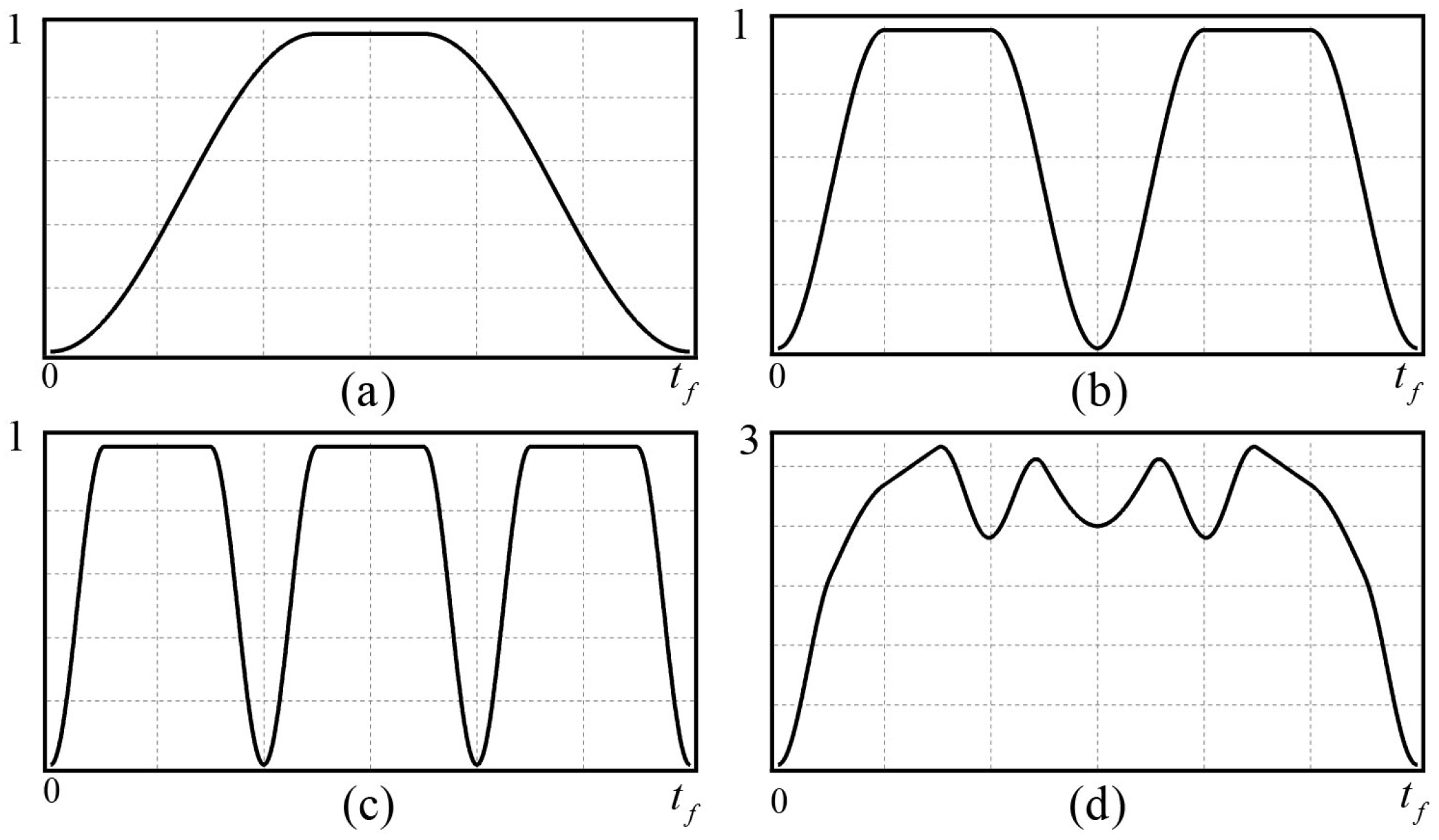
12), we can obtain the basis function trajectory shown in
Figure 2.
Figure 2a shows the one-order basis function trajectory,
Figure 2b shows the two-order basis function trajectory, and
Figure 2c shows the three-order basis function trajectory. The one-order, two-order, and three-order basis function trajectories are superimposed by the basis function superposition method to form the superposition trajectory shown in
Figure 2d.
3.3. Parameter Optimization Based on PSO Algorithm
This section describes how to use the PSO algorithm to optimize the trajectory parameters. It mainly includes the construction of the fitness function and the optimisation process for the parameters.
After obtaining the angular velocity trajectory of the PTLUM’s active joint by means of basis function superposition, the parameters in the trajectory need to be optimized according to the constraints of Equation (
6) to meet the optimization objectives.
Combining Equations (
7) and (
11), it can be seen that
at
. Therefore, the constraint component of the active joint’s velocity need not be included in the fitness function. According to the underactuated constraint relationship given by Equation (
6), it is possible to determine the passive joint’s angle trajectory and angular velocity trajectory.
The fitness function
h is set to ensure that the planned trajectory enables the active and passive joints to reach their target positions while their angular velocities are zero:
where
,
,
,
, and
represent the active link angle, the passive link angle, the angular velocity, and the target states of the active joint and passive joint, respectively.
The rules for updating the position and velocity of the particle swarm are as follows:
where
w is the inertia weight,
is the individual learning factor,
is the group learning factor, and
and
are the position and velocity of the particle swarm, respectively.
The inertia weight w determines the particle’s trust in its own historical speed, which affects its global search and local exploration abilities. The larger w is, the stronger the global search ability, the smaller w is, the stronger the local search ability. The values of w are usually selected in the range of 0∼1. and determine the influence of the empirical information of the particle itself and the empirical information of other particles on the particle trajectory, which reflects the information exchange between the particle swarms. The values of and are usually selected in the range of 1∼2. The number of iterations G is related to whether the optimization can be successful. If the number of iterations G is too low, there is a failure to converge to a given fitness value within the specified number of iterations G. The number of iterations G is determined by the dimension of the optimization problem. Generally, within the range 50∼200, the more complex the optimization problem, the greater the number of iterations G that is required.
The position of the population
is taken as a trajectory parameter to get the active joint trajectory according to Equations (
8) and (
10). The passive joint trajectories are obtained by calculating the constraint relationship in Equation (
6).
The following are the specific steps to optimize the trajectory parameters by PSO:
- Step 1:
Random initialization of and —set the PSO algorithm parameters, the number of iterations G, the number of particles N, the inertia weight w, learning factors and , and input the initial state and target state of the system;
- Step 2:
According to Equations (
8) and (
10),
and
are calculated; according to the underactuated constraint relation of Equation (
6),
and
are calculated;
- Step 3:
Calculate the fitness value
h combined with Equation (
13);
- Step 4:
If h is less than (a small positive number), the output is . If not, update the population position and velocity and go back to Step 2.
The computational complexity of the PSO algorithm mainly includes time complexity and space complexity. Space complexity describes the data storage requirements of the PSO algorithm at runtime, which mainly depend on the number and dimensions of the particles. In this paper, the number of parameters to be optimized is nine, so the space dimension is nine. The space required to store them is much lower than that of conventional computer memory, so it is not necessary to consider space complexity. The computational complexity of the PSO algorithm is mainly affected by time complexity. Time complexity includes three stages: initialization, iteration, and termination. The most time-consuming of them is the iteration stage, accounting for more than 95% of the total time.
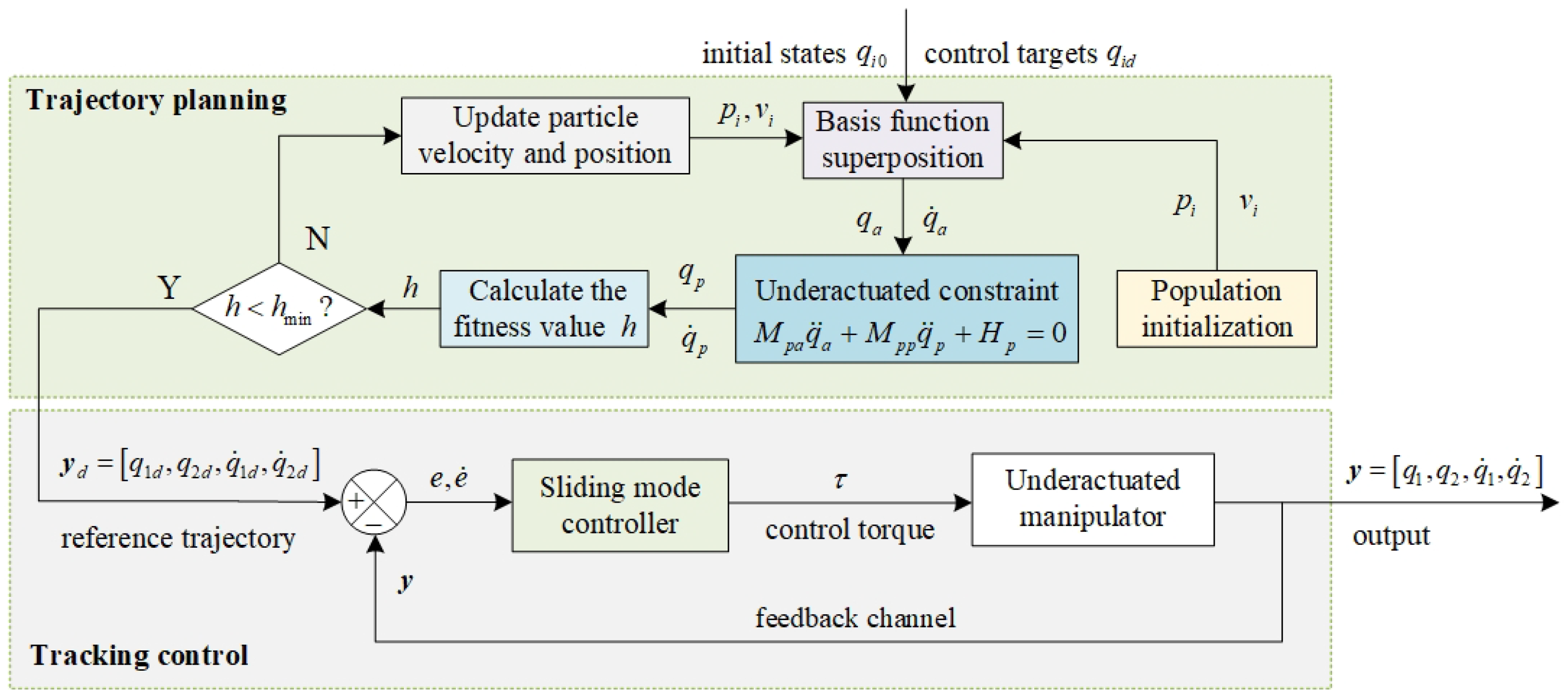
Figure 3 shows the framework of trajectory planning and tracking control. The upper portion of
Figure 3 depicts the trajectory planning procedure. The initial state
, the target state
, and the initialized particle swarm
are input into the basis function superposition module; the active joint angle trajectory
and the angular velocity trajectory
are calculated. Then the active joint trajectory is brought into the underactuated constraint relationship to obtain the trajectory of the passive joint, and the fitness value
h is calculated and compared with
. If
h is less than
, trajectory planning is achieved, and the optimized target trajectory is input into the control part. If
h is greater than or equal to
, the
and
of the particle swarm are updated, and the iteration is continued until
h <
or the set number of iterations is reached. The question mark symbol symbol in
Figure 3 indicates the judgment of whether
h is less than
.
4. Controller Design
This section designs an SMC to track the planning trajectory. When a joint of a planar two-link manipulator system is damaged, the system is transformed into a PTLUM system. The underactuated joint does not have any driving ability, and the underactuated link can only be pulled to the target position by the action of the active joint. Consequently, we decided to use the metaheuristic algorithm to plan the active link’s trajectory and design the SMC to achieve the control objective.
Figure 3 displays the control system’s composition. After the trajectory parameters
obtained by the metaheuristic algorithm are brought into Equations (
8) and (
10), the planned reference trajectory
is obtained. The error between the reference trajectory
and the actual trajectory
y is used as the input of the SMC, and the torque is used as the control output to drive the link motion.
Let the state space variable of the PTLUM system be .
According to Equation (
2), it can be concluded that
Expanding Equation (
15), we can get
where
where
,
,
,
,
, and
have been given in
Section 2.
When the system is a PP,
; when the system is a PA,
. Since
is a positive definite symmetric matrix, there is no singularity in the Equation (
16).
According to the selection of state variables and the Equation (
16), the equation of state is obtained as
where
The following equation is the construction of the sliding surface:
where
is a positive number
where
e and
are the angular and velocity tracking errors, respectively.
The derivation of
S yields
Generally, the exponential convergence law is
, but the jump of the sign function at the zero point will cause chattering. Therefore, we use the
with continuous zeros to approximate the sign function
where
and
are constant, and
is a small positive number.
In order to reduce the chattering effect caused by the sign function, we use
instead of the sign function. The controller is obtained by deducing from Equations (
20) and (
21) as follows:
Choose the Lyapunov function as
Deriving Equation (
23) and combining Equations (
20) and (
21), we have
When
,
,
V is a radial unbounded function. When
,
, according to the LaSalle’s invariance principle [
25], the system is asymptotically stable.
5. Simulations
To verify the efficacy of the trajectory planning algorithm and control approach suggested in this research, simulation tests are conducted on the PTLUM system. In Simulation I, the initial state, target state, and chosen structural parameters are identical to those found in Ref. [
26]. Simulation II selected different structural parameters from Simulation I. Based on Simulation II, Simulation III establishes distinct initial and target states.
The PSO algorithm in the three groups of simulations selects the same variable selection domain. The constraint domain of the superposition coefficients , and of the basis function is set to [−4, 4]. The constraint domain of the basis function peak time is , the constraint domain of the basis function peak time and is , and the constraint domain of the basis function peak time is , , and is .
The initial angle and target angle of the three sets of simulations are shown in
Table 1. The initial angular velocity and the terminal angular velocity of the three groups of simulations are both 0 rad/s. The structural parameters of the PTLUM in the three groups of simulations are shown in
Table 2. After simulation tests, the optimization can be completed within the iterative upper bound when the trajectory time is
s.
Table 3 displays the trajectory parameters that were acquired following the optimization process.
5.1. Simulation I
Simulation I selects the same initial state, target state, and structural parameters as those in Ref. [
26], as shown in
Table 1 and
Table 2.
5.1.1. Simulation I for the PP System
The PSO parameters are as follows: iteration times
G = 100, number of particles
, inertia weight
w = 0.8, and learning factors
=
= 1.5. The results obtained by the optimization algorithm are shown in the second column of
Table 3. The following are the parameters of SMC:
= 0.20,
= 1.00,
= 1.30,
. According to the trajectory parameters in
Table 3, the reference trajectory can be obtained by combining Equations (
8) and (
10), and then the designed SMC controller is used to track the trajectory to enable the PP system to reach the target state.
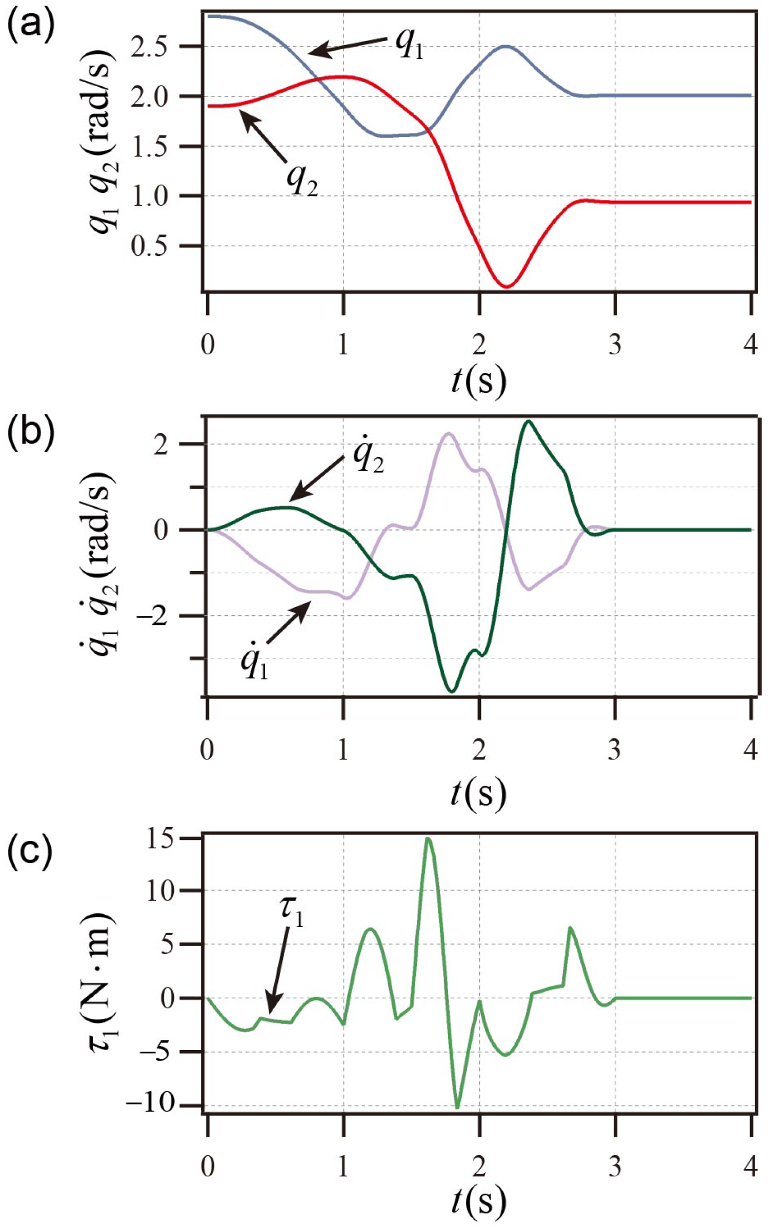
As shown in
Figure 4a,b, the PP system achieves the control objectives; the PP system’s active link torque curve is displayed in
Figure 4c.
Figure 4 illustrates that the PP system reaches the goal state prior to
s and maintains stability following
s, and the peak velocity is less than
rad/s, and the peak torque does not exceed
. Compared with the stability time of more than 6 s in Ref. [
26], it has the advantage of shorter stabilization time.
5.1.2. Simulation I for the PA System
The PSO parameters are as follows: iteration times
G = 100, number of particles
, inertia weight
w = 0.8, learning factors
=
= 1.5, minimum fitness function value
= 0.0005. The results obtained by the optimization algorithm are shown in the third column of
Table 3. The following are the parameters of SMC:
= 0.25,
= 1.10,
= 1.25,
.
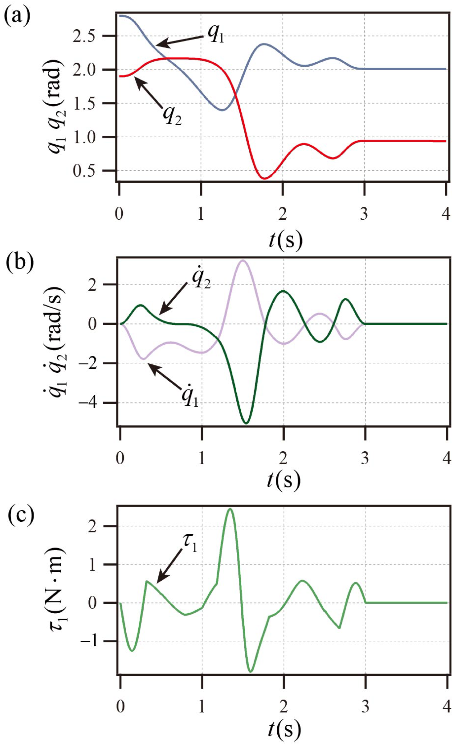
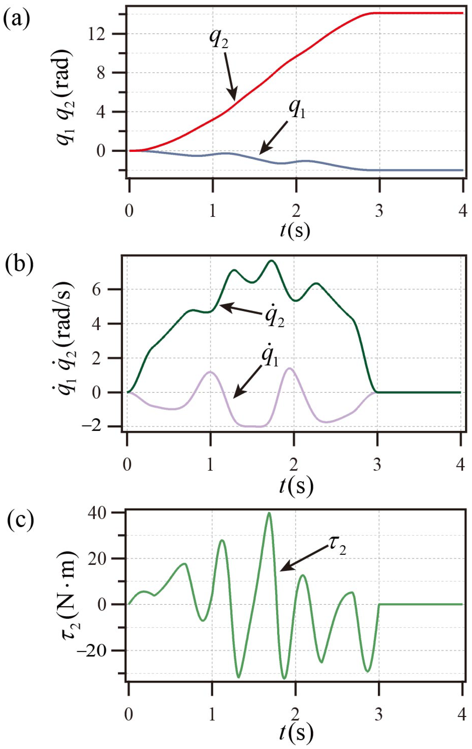
As shown in
Figure 5a,b, the PA system achieves the control objectives shown in
Table 1. The PA system’s active link torque curve is displayed in
Figure 5c.
Figure 5 illustrates that the PA system reaches the goal state prior to
s and maintains stability following
s, and the peak velocity is less than
rad/s, and the maximum torque does not exceed
. The stability time in [
26] is more than 3 s, the peak torque is close to 80
, and the peak angular velocity is close to 30 rad/s. Compared with [
26], it has the advantages of shorter stability time and smaller peak angular velocity and peak torque.
5.2. Simulation II
To confirm that the control mechanism remains successful when different structural characteristics are chosen, simulation II selects different structural parameters from Simulation I, as shown in
Table 2.
Table 1 demonstrates that both the initial and final states are consistent with Simulation I.
5.2.1. Simulation II for the PP System
The PSO parameters are as follows: iteration times
G = 100, number of particles
, inertia weight
w = 0.8, learning factors
=
= 1.5, minimum fitness function value
= 0.0005. The results of the trajectory parameters obtained by the optimization algorithm are shown in the fourth column of
Table 3. The following are the parameters of SMC:
= 0.22,
= 1.15,
= 1.10,
.
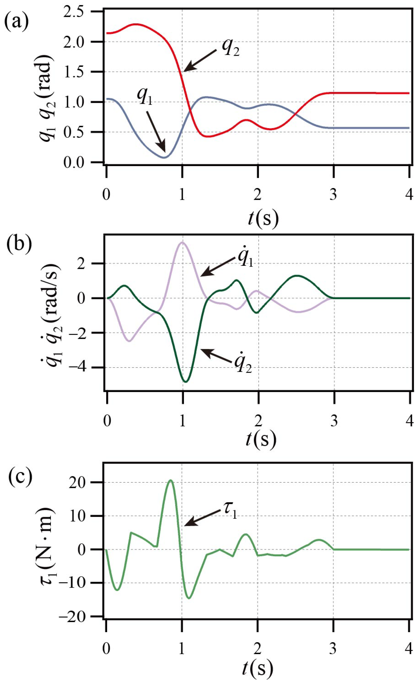
As shown in
Figure 6a,b, the PP system achieves the control objectives shown in
Table 1. The PP system’s active link torque curve is displayed in
Figure 6c.
Figure 6 illustrates that the PP system reaches the goal state prior to
s and maintains stability following
s, and the peak velocity is less than
, and the maximum torque does not exceed
. Compared with Simulation I, the reason for the larger peak torque is that the mass of the active link in the system structure parameters increases from 0.2 kg to 0.5 kg. The decrease in the maximum angular velocity is due to the increase of the length of the active link in the system’s structure parameters from 0.5 m to 1.0 m.
5.2.2. Simulation II for the PA System
The PSO parameters are as follows: iteration times
G = 100, number of particles
, inertia weight
w = 0.8, learning factors
=
= 1.5, and minimum fitness function value
= 0.0005. The results of the trajectory parameters obtained by the optimization algorithm are shown in the fifth column of
Table 3. The following are the parameters of the SMC:
= 0.15,
= 1.20,
= 1.28,
.
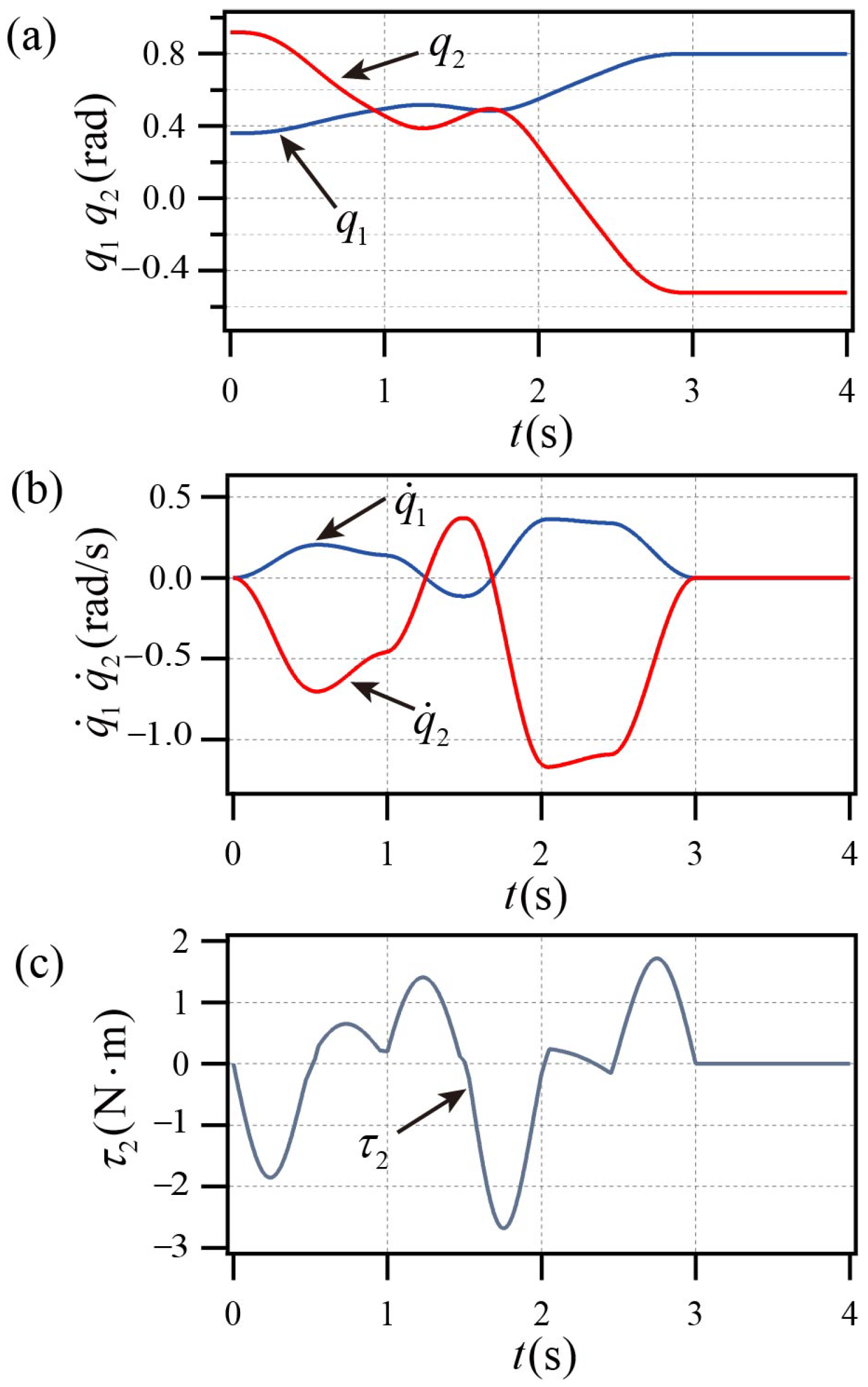
As shown in
Figure 7a,b, the PA system achieves the control objectives shown in
Table 1. The PA system’s active link torque curve is displayed in
Figure 7c.
Figure 7 illustrates that the PA system reaches the goal state prior to
s and maintains stability following
s, and the peak velocity is less than
rad/s, and the maximum torque does not exceed
. Compared with simulation I, the reason for the larger peak torque is that the mass of the active link in the system structure parameters increases from 1.0 kg to 1.5 kg. The decrease of the maximum angular velocity is due to the increase of the length of the active link in the system structure parameters from 1.0 m to 2.0 m.
5.3. Simulation III
As indicated in
Table 1, simulation III sets various initial states and target states than simulation I in order to confirm that the control mechanism remains effective in diverse initial states and target states. As seen in
Table 2, the PTLUM system’s structural parameters equal those of simulation I.
5.3.1. Simulation III for the PP System
The PSO parameters are as follows: iteration times
G = 100, number of particles
, inertia weight
w = 0.8, learning factors
=
= 1.5, minimum fitness function value
= 0.0005. The results obtained by the optimization algorithm are shown in the sixth column of
Table 3. The following are the parameters of SMC:
= 0.25,
= 1.24,
= 1.20,
.
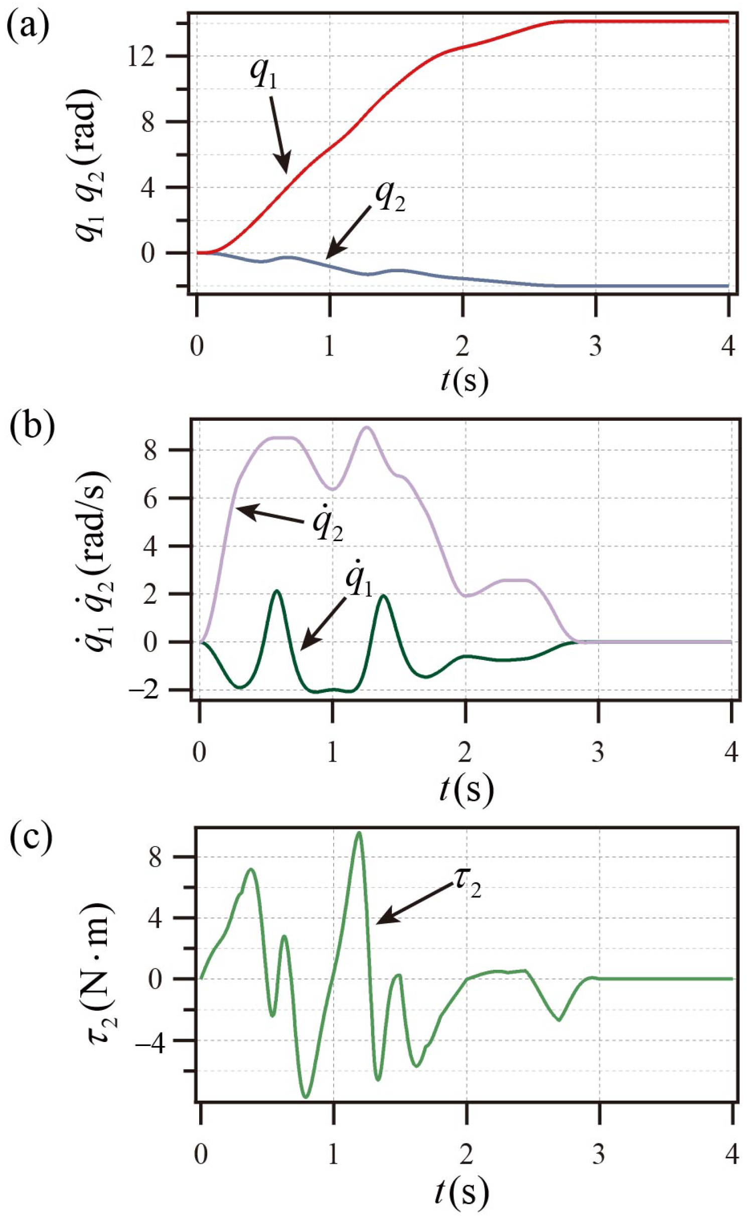
As shown in
Figure 8a,b, the PP system achieves the control objectives shown in
Table 1.
Figure 8c shows the active linkage torque curve of the PP system.
Figure 8 illustrates that the PP system reaches the goal state prior to
s and maintains stability following
s, and the peak velocity is less than
rad/s, and the maximum torque does not exceed
.
5.3.2. Simulation III for the PA System
The PSO parameters are as follows: iteration times
G = 100, number of particles
, inertia weight
w = 0.8, learning factors
=
= 1.5, minimum fitness function value
= 0.0005. The results obtained by the optimization algorithm are shown in the seventh column of
Table 3. The following are the parameters of SMC:
= 0.23,
= 1.16,
= 1.22,
.
As shown in
Figure 9a,b, the PA system achieves the control objectives shown in
Table 1.
Figure 9c shows the active linkage torque curve of the PA system.
Figure 9 illustrates that the PA system reaches the goal state prior to
s and maintains stability following
s, and the maximum velocity does not exceed
rad/s, and the maximum torque does not exceed
.
5.4. Simulation Results Analysis
The parameters selection of the three groups of simulation trajectory parameters optimization algorithms is consistent as follows: iteration times
G = 100, number of particles
, inertia weight
w = 0.8, learning factors
=
= 1.5, minimum fitness function value
= 0.0005. The optimization goal can be completed under this parameters selection, indicating that the optimization problem is not difficult and is not sensitive to parameters selection. After testing, the trajectory end time
= 3 s is a small and easy to obtain time. If you want to continue to shorten
, you need to modify the algorithm parameters to adapt to the change. The parameters of SMC are set by empirical method. In order to ensure the control effect, the SMC parameters of each group are not consistent. Three groups of simulations show that the proposed method is effective and can adapt to PTLUM with different parameters and states. Additionally, the method in this work can successfully reduce the peak torque, the maximum angular velocity, and the control time, according to a comparison of the simulation results with previous studies [
26].
The method proposed in this paper also has some limitations. The PSO algorithm optimization in this paper is carried out offline, and the real-time performance is insufficient in engineering practice. Trajectory planning and tracking control methods are based on nominal models without considering model uncertainties and disturbance factors.

